Article

Dynamic Instability Analysis of a Double-Blade Centrifugal Pump

1
College of Metrology and Measurement Engineering, China Jiliang University, Hangzhou 310018, China
2
Zhejiang Leo Group Co., Ltd., Taizhou 317511, China
3
Zhejiang Nanyuan Pump Co., Ltd., Huzhou 313219, China
4
Zhijiang College, Zhejiang University of Technology, Shaoxing 312030, China
*
Authors to whom correspondence should be addressed.
Appl. Sci. 2021, 11(17), 8180; https://doi.org/10.3390/app11178180
Submission received: 10 August 2021 / Revised: 30 August 2021 / Accepted: 31 August 2021 / Published: 3 September 2021
(This article belongs to the Section Acoustics and Vibrations)

Abstract

:
The flow instability of a double-blade centrifugal pump is more serious due to its special design feature with two blades and large flow passages. The dynamic instabilities and pressure pulsations can affect the pump performance and operating lifetime. In the present study, a numerical investigation of unsteady flow and time variation of pressure within a complete double-blade centrifugal pump was carried out. The time domain and frequency domain of pressure pulsations were extracted at 16 monitoring locations covering the important regions to analyze the internal flow instabilities of the pump model. The frequency spectra of pressure pulsations were decomposed into Strouhal number dependent functions. This led to the conclusion that the blade passing frequency (BPF) related vibrations are exclusively flow-induced. Large vortices were observed in the flow passages of the pump at low flow rate. It is noted that high vorticity magnitude occurred in the vicinities of the blade trailing edge and tongue of the volute, due to the rotor-stator interaction between impeller and volute.

1. Introduction

Double-blade centrifugal pumps are widely used to transport liquids containing solid particles, for instance, wastewater treatment, chemical process and liquid food transportation. The impeller with two blades can be capable of handling the liquids with large solid particles or long fibers, due to its larger flow passages [1]. However, compared with multi-blade centrifugal pump, the internal flow instability of the double-blade centrifugal pump is more serious, and the corresponding slip is increased, because the flow control capability of the impeller is decreased due to its large passage. From an engineering viewpoint, to extend the operating lifetime of double-blade centrifugal pump, we should focus on lowering the vibration level of the pump. Typically, the vibration generated in a centrifugal pump consists of tonal components and broadband components. Tonal components are often dominated by the tones at blade passing frequency and its harmonics [2,3,4]. This is a consequence of the strong interaction between the impeller and tongue of volute [5,6]. Additionally, broadband vibration is generated by flow separations on the impeller blades or pump volute, turbulence boundary layers, back flow and vortices [7,8,9].
Studies on the flow instability of centrifugal pumps are numerous. In the early stage, Guelich et al. [10] pointed out that pressure pulsations in centrifugal pump are created by the unsteady flow, for instance, the wake flow from impeller blade trailing edge, the large-scale turbulence and vortices generated by flow separation and flow recirculation at part load conditions. Afterwards, Spence et al. [11] adopted the numerical methods to investigate the pressure pulsations and unsteady flow inside the pump, and a better agreement between computational fluid dynamics (CFD) data and experimental data was achieved. Pavesi et al. [12] carried out the study on flow instability of a centrifugal pump, and a correlation between the fluid dynamics and the emitted noise was investigated. It was identified that a fluid-dynamical origin is connected with the jet-wake phenomenon. Recently, the flow instability of a multistage centrifugal pump at off-design conditions was investigated by Shibata et al. [13]. Pressure pulsations at diffuser inlet were measured and rotating stall phenomenon was observed with CFD tools. In addition, some studies were carried out to do the deep analysis on the unsteady flow phenomena in centrifugal pump, for instance, flow separation [14,15,16], rotating stall [17,18,19] and recirculation [20,21]. Those directly cause the formation of flow instability, pressure pulsations and pump vibration.
Although much work has been done on flow instability of centrifugal pump, there is sparse literature available to analyze the flow instability and vibration characteristics of a double-blade centrifugal pump. Thus, the objectives of this study are: (1) identify the unsteady flow phenomena and pressure pulsations of the double-blade centrifugal pump; (2) evaluate the vibration characteristics and its relationship with flow instability; (3) explain the flow instability generating mechanism of double-blade centrifugal pump.

2. Computational Modeling and Experimental Test

2.1. Pump Model

A typical double-blade centrifugal pump with large flow passages is selected as a study object. Basically, the pump is constructed with an impeller with two blades, volute, gas-liquid separation chamber, suction, shaft, shaft seal and key (shown in Figure 1). The fluid domains were constructed to do the fluid simulation. Both the designed operation parameters and pump geometrical parameters were illustrated in Table 1.

2.2. Simulation Setup

The ANSYS CFX 19.0 was used as a simulation tool. In the simulation, the inlet boundary condition was set at total pressure (1 atm), and the outlet boundary condition was set as mass-flow. Impeller is the rotating part, and other parts are the stationary parts. Both steady simulation and transient simulation strategies were undertaken in the research. In the steady calculation, the interface between the rotating impeller and the volute was set as the frozen rotor, and in the transient calculation, it was set as the transient rotor-stator interface. The spatial discretization of the governing equation is based on the finite volume method, and the transient calculation time step is 1.72414 × 10⁻⁴ s, which is 1/120 of the rotation period. The high resolution is selected for advection scheme, transient scheme is second order backward Euler, turbulence numeric is high resolution, the convergence target is set to 10−5, and the maximum number of iteration steps in each time step is 15. Standard wall function was used to process the near wall surface, and the solid wall surface was set to be no slip. In addition, the impeller, gas-liquid separation chamber, suction, and volute wall surface were set to rough wall surfaces with a roughness of 0.04 mm, and the remaining solid walls were set to smooth wall surface.
The quality of the grid directly affects the accuracy and time of numerical calculation. In the CFD calculation, the structured meshes were constructed using Gridpro software, as shown in Figure 2. The grid sensitivity analysis was carried out to determine the appropriate number of grids. Figure 3 shows that as the number of cells exceeds about 3 million, the head and torque basically remain constant and their values are about 16.7 m and 19.4 N·m under designed flow rate condition. In order to balance the calculation accuracy and calculation time, the total mesh number of the final model was set at 4.4 million, in which the number of cells of impeller, volute, gas-liquid separation chamber and suction channel are 680,000, 460,000, 215,000, 170,000, respectively; and the remaining parts of the computational domain consists of 940,000 cells. Table 2 shows the verification results of the independence of turbulence models under designed flow rate condition. It can be seen that the influence of different turbulence models on the calculation results is small, and the relative error is lower than 3%, which satisfies the precise requirements of the relevant calculation. In this study, SST k-ω was selected as the turbulent model for subsequent calculation, because it can obtain the wall separation flow and shear flow under the off-design condition well [22,23,24].

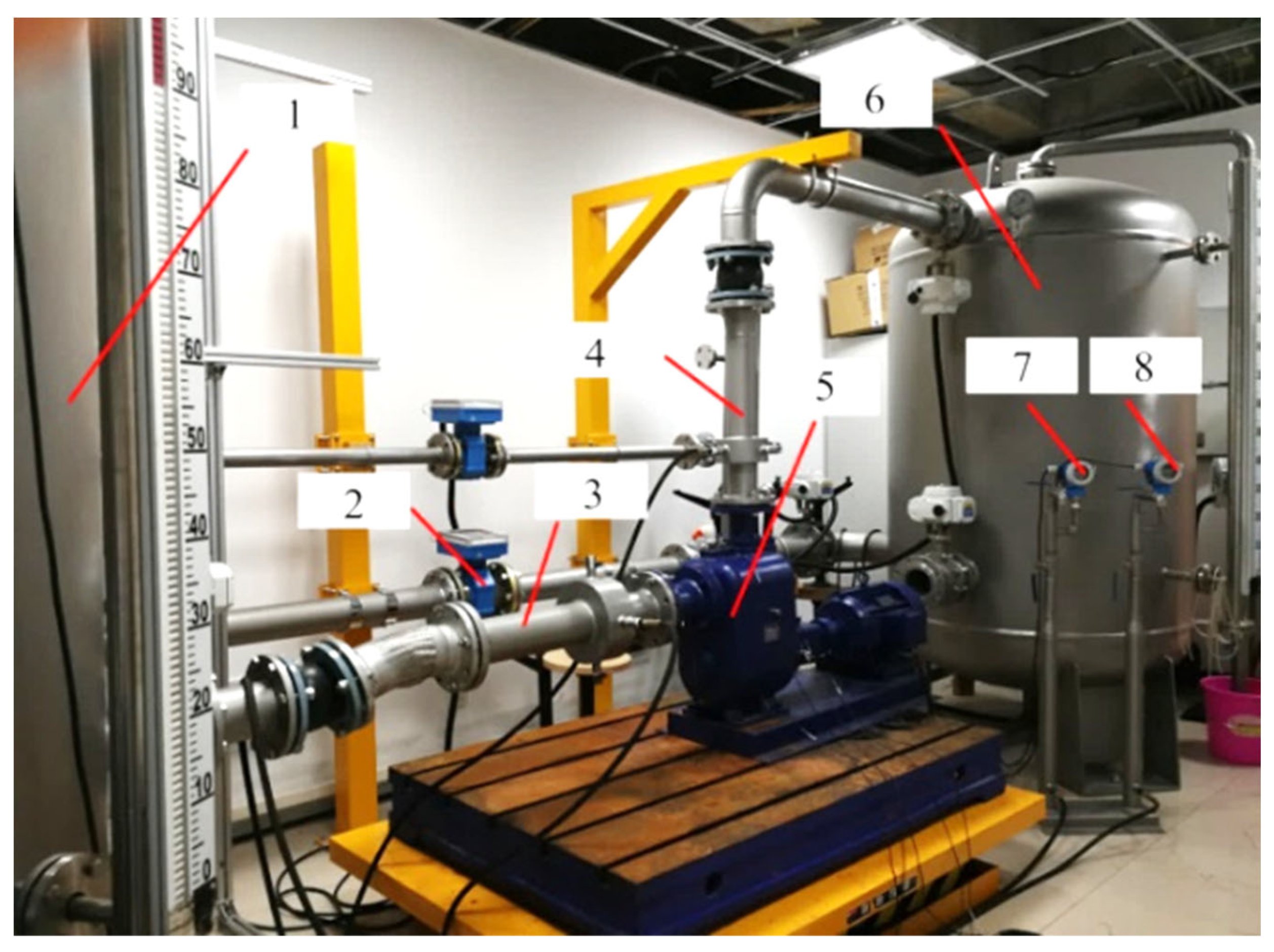
2.3. Experimental Setup

The pump is directly driven by a Siemens motor and the speed is controlled by an ABB frequency converter. Figure 4 presents the pump test rig. It includes: 1-inlet tank, 2-flow meter, 3-inlet pipe with pressure detecting port, 4-outlet pipe with pressure detecting port, 5-test pump, 6-outlet tank, 7-inlet pressure transducer, and 8-outlet pressure transducer. To ensure a stable water flow at the pump inlet, the inlet tank was equipped with a flow straightener for stabilizing the flow. The error of the measuring devices is as follows: (1) the pressure error is ±0.2%; (2) the flow rate error is ±0.2%; (3) the speed error is ±1 rpm; (4) the power error is ±1.5%. In addition, the repeatability of test fills the ISO 9906-2012 Grade 1 requirement.
Additionally, a piezoelectric vibration acceleration sensor and a signal acquisition and analysis system were used to measure the vibration levels of the pump. According to the requirements of ISO 10816 [25], 5 vibration acceleration monitoring points were arranged in the vibration sensitive area of the pump unit to obtain sufficient vibration information, see in Figure 5. No. 1 measuring sensor is located on top of pump housing (Z direction), No. 2 measuring sensor is located on side wall of pump housing (Y direction), No. 3 measuring sensor is located on foot of pump housing (Z direction), No. 4 measuring sensor is located on bearing housing (Z direction), No. 5 measuring sensor is located on bearing housing (Y direction). The technical information of acceleration sensors was described in Table 3. However, the special design feature of the pump volute is that it was covered by chamber, so it is difficult to mount the dynamic pressure sensors in the pump volute to measure the dynamic pressure pulsations. Therefore, the vibration data were measured as a limited experimental dataset to explain the dynamic instability of the pump.

2.4. Layout of Monitoring Points

In order to study the pressure pulsation characteristics at different positions of the volute and the impeller by CFD, 10 monitoring points were arranged in the middle section of the volute, and 6 monitoring points were arranged at the mid-span of blade suction and pressure surface from inlet to outlet (shown in Figure 6). In detail, P1 is located at tongue area, P2–P9 are located at different section of volute, and P10 is located at diffuser area. X1–X3 are the three monitoring points from inlet to outlet of the blade suction surface, and Y1–Y3 are the three monitoring points from inlet to outlet of the blade pressure surface.

2.5. Simulation Validation

A comparison between the numerical results and the experimental results is shown in Figure 7. The disc friction loss is taken into account in the computation of the efficiency. Equations of disc friction loss can be found in [26]. It can be found that both the head and efficiency error at the designed condition are less than 2%; however, at part-load flow rates, the maximum error of head and efficiency is up to 5%. The main reason is that at part-load flow rate, the flow structures inside the pump are very complicated and unstable, which leads to large deviations in calculation and test. In general, the numerical calculation results are in good agreement with the experimental results, and the accuracy basically meets the requirements of subsequent calculation and analysis. In addition, the typical flow rates, e.g., 0.4Qd, 0.6Qd, 0.8Qd, 1.0Qd, and 1.2Qd, were selected to do the further analysis.

3. Results and Discussion

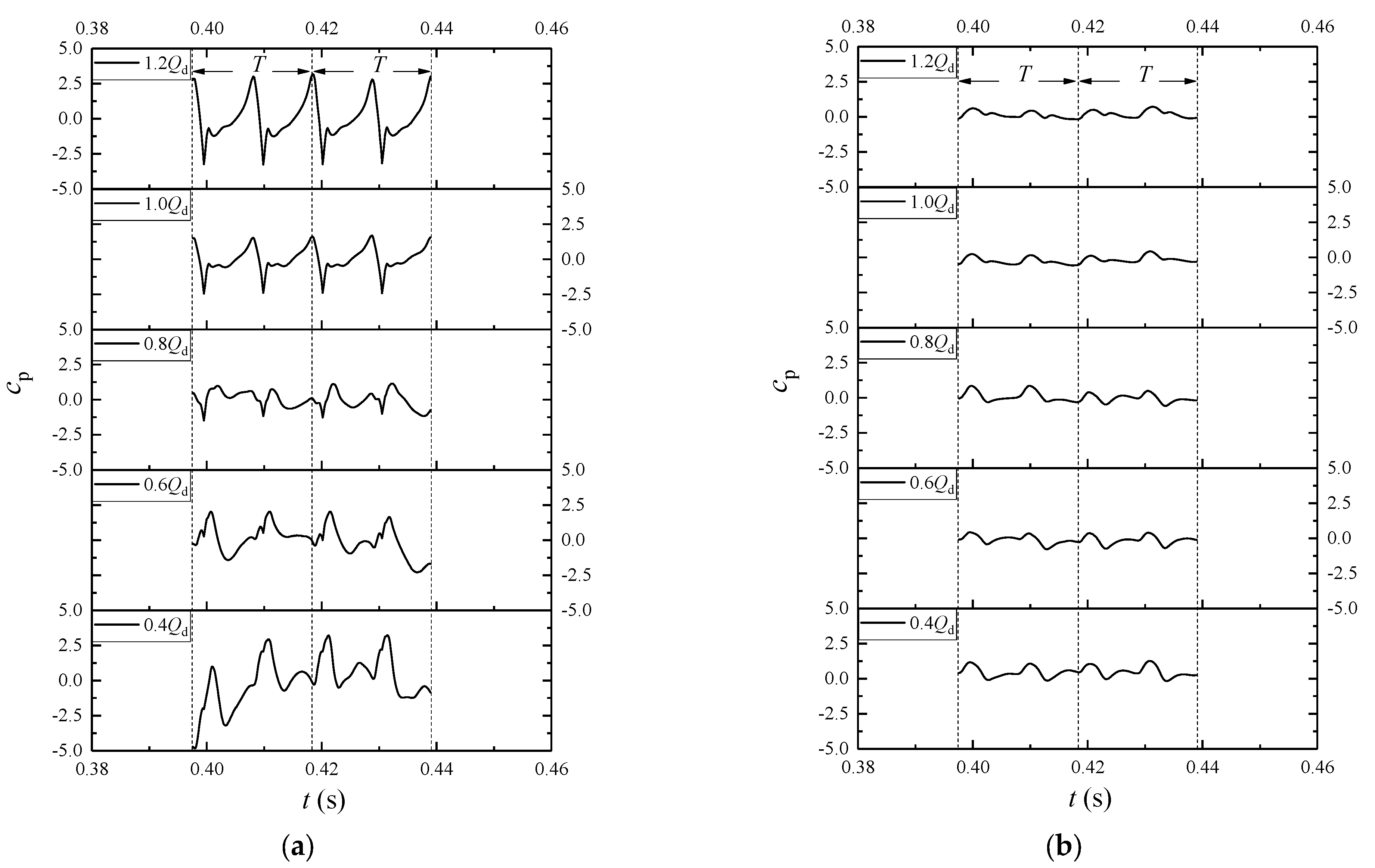
3.1. Pressure Pulsations of Volute at Different Flow Rates

The dimensionless unsteady pressure coefficient is calculated in Equation (1), which is a normalization of the obtained pressure values based on the dynamic pressure in the impeller outlet ( 0.5 ρ u 2 2 ). The intensity of pressure pulsation µp can be calculated in Equation (3) and the frequency of pressure pulsations is decomposed into Strouhal number (St) in Equation (4).
c p = p i p ¯ 0.5 ρ u 2 2
p ¯ = 1 N i = 1 N p i
μ p = i = 1 N ( p i p ¯ ) 2 N / ( 0.5 ρ u 2 2 )
St = f z f n = f BPF
where N = 120 is the number of samples.
Figure 8 presents the intensity of pressure pulsations at different monitoring points in volute under different flow rates. It is noted that pump volute is asymmetry by having a feature of a tongue. The flow passage in the tongue area is quite narrow and pressure changes dramatically under the interference between impeller and tongue. The vicinity of the tongue (P1–P3) is the area with the most serious pressure pulsation in the entire volute channel. For the P1–P3 monitoring points, the change of flow rate caused the change of the pressure pulsation amplitude.
At 0.4Qd, the change of pressure near the tongue area (P2) was the most significant (shown in Figure 9a). As the relative gap between the impeller outlet and the volute wall surface increases, the intensity of rotor-stator interference weakens, and the influence of the flow rate on the pressure pulsation decreases. For the P4–P6 monitoring points, the pressure pulsation amplitude of different flow rates is getting smaller (shown in Figure 8). For the P7 monitoring point, the pressure pulsation amplitude achieves the minimum value (shown in Figure 8), and the changes in flow rate have a slight effect on pressure pulsation (shown in Figure 9b). In Figure 9, the data were captured from the last two rotation cycles of impeller, and the time required for one rotation cycle (T) is about 0.02 s. There are two main peaks and valleys in one rotation cycle that is directly linked to the number of blades (z = 2). At the same time, this also shows that the rotor-stator interference between the pump’s dynamic part (impeller) and static part (volute) was the main source of pressure pulsation at each monitoring point.
Frequency spectra of pressure pulsations at the volute under different flow rates are shown in Figure 10. It is presented that the domain frequencies of the pressure pulsation under different flow rates are the blade passing frequency (St = 1) and its multipliers (St = 2, 3, 4 and etc.). At 1.2Qd, the amplitude of pressure pulsation at the blade passing frequency is larger when the interaction occurs in the vicinity of the tongue at P2. However, at P7, the high amplitude of pressure pulsation occurs at a low flow rate (0.4Qd). In addition, especially at P2, it is noted that the broadband pulsation occurs at 0.4Qd, which means some unsteady flow structures could be generated at this area, e.g., vortex, backflow and flow separation. This is clearly shown in Figure 11, where the backflow phenomena are presented in the outlet of impeller, and some vortices are produced near the suction side of the blade.
Actually, the flow fields at t0 and t2 are quite similar, and the flow field at t1 is quite similar to that at t3, thanks to the effect of the relative position of blade to tongue of volute. Instantaneous fields of vorticity magnitude at the low flow rate are illustrated in Figure 11c. The vorticity magnitude Ω was calculated according to the definition of the new omega vortex [27]. High vorticity magnitude is occurred in the vicinities of the blade trailing edge and tongue of volute, due to the rotor-stator interaction between impeller and volute. The vorticity magnitude layer on the suction side of the blade shows the flow separation.
Figure 12 shows the flow velocity streamlines of the pump under different flow rates. It can be found that the flow separation is weakened as the flow rate increases. At 1.0Qd and 1.2Qd, there is no vortex inside the pump. It is clear evidence to support the low-pressure pulsation under the designed flow rate.

3.2. Pressure Pulsations of Impeller at Different Flow Rates

Figure 13 shows the pressure pulsations of different monitoring points in impeller at different flow rates. There is no rotor-stator interference in the impeller flow channel, but unsteady flow phenomena such as flow separation, backflow, and stalls make the pressure pulsation characteristics in the impeller flow channel more complicated. Compared with the periodic pressure pulsation in the volute, the periodicity of the pressure pulsation in the impeller is obviously weakened. For the suction side of the blade (X1–X3), the pressure pulsation amplitude is relative stable and fluctuates in the range of ±0.5. The change of flow rate has a slight effect on the pluses at X1–X3. However, for the pressure side of the blade (Y1–Y3), the amplitude of the pressure pulsation changes greatly due to the jet-wake effect. Especially, near the trailing edge of blade pressure surface (Y3), the amplitude of pressure pulsation is at the highest level.
In order to reveal the spectrum characteristics of impeller at different flow rates, the typical point X3 and Y3 were selected for further spectral analysis. The spectra of pressure pulsation at X3 and Y3 are presented in Figure 14. For all the cases, the main excitation frequencies for the pressure pulsation at X3 and Y3 are impeller rotational frequency and blade passing frequency (BPF).

3.3. Loads of Blade under Different Flow Rates

Figure 15 presents the distribution of radial force Fx and Fy on X and Y direction of a blade during one single rotation. It is obvious to discover that the shape of Fx and Fy like a dipole under different flow rates due to the effect of two blades. It further notes that a bigger force on the blade is generated when a blade passes the tongue of the volute. On the contrary, when the blade is away from the tongue of the volute, the radial force is smaller. In addition, comparing the radial forces at different flow rates, it can be seen that the largest radial forces were generated at 0.4Qd. This is caused by the uneven pressure distribution. However, the lowest radial forces were found at 1.0Qd.

3.4. Vibration Characteristics of Pump

To evaluate the vibration levels and main excitation frequencies of the pump model under different flow rates, one typical vibration spectrum was obtained in Figure 16. This indicates that the frequencies at St = 1, 2, 3, 4 and 5 are the main excitation frequencies which induce pump vibration.
By comparing the vibration levels of different measuring points, the acceleration data at main excitation frequencies were calculated for five vibration measuring points under different flow rates (shown in Figure 17). In Figure 17a, for the No. 1 measuring point, the vibration level at St = 1 is higher than others. Moreover, the vibration level at 0.4Qd is highest and its value is about 4.3 mm2/s, while the lowest vibration level can be found at 1.0Qd. From Figure 17b, the vibration level at St = 1 of No. 2 measuring point is lower than that of No. 1 measuring point. However, the vibration levels at St = 2, 3, 4 and 5 are higher than those of No. 1. As can be seen in Figure 17c,d, the distribution of vibration levels of No. 3 and 4 measuring points at different Strouhal numbers are similar to No. 1 measuring point. Figure 17e presents that the overall vibration level of No. 5 measuring point is lower than others. This indicates that the low vibration energy was generated at pump feet.

3.5. Relationship between the Unsteady Flow and the Structural Vibration

As discussed above, the rotating flow instability of impeller is coupled to the unsteady flow fluctuations in the impeller flow passages. High intensive pressure pulsations are generated near the trailing edges of blade surfaces, due to the destabilized passage flow by interacting between impeller blades and volute, especially near the tongue of volute. It is believed that this is a major source of fluid-induced vibration. By analyzing the pressure pulsations spectra of volute (Figure 10) and vibration spectra of pump (Figure 17), it can be seen that the peak at blade passing frequency (St = 1) generates more vibration energy than the other frequencies at St = 2, 3, 4 and 5. This demonstrates that the spectral peaks that correspond to multiples of the number of impeller blades are the main contributors to the pump vibration.

4. Conclusions

In this study, the flow instability of a double-blade centrifugal pump was investigated. The following specific conclusions can be obtained:
(1)
The region in the pump experiencing the largest pressure pulsation is located at the vicinity of tongue of volute. The amplitude of pressure pulsation decreases as the relative gap between the impeller outlet and the volute wall surface increases. The rotor-stator interference between the impeller and volute is the main source of pressure pulsation. Highly intensive pressure pulsation is found at part-load conditions due to serious flow instability.
(2)
A strong vorticity fields in the vicinities of volute tongue and suction side of impeller blade were observed. These vortices are unstable, and they influence the normal flow streamlines, and destabilize the radial forces on each blade. Additionally, the interaction between blade and tongue causes the dynamic fluctuation of blade loads.
(3)
The main excitation frequencies were identified by measuring the vibration data of the double-blade centrifugal pump. In general, vibration amplitude at blade passing frequency (St = 1) is higher than others. There is a direct link between pressure pulsation and pump vibration, and pressure pulsation is a major source of fluid-induced vibration.
(4)
Considering the difficulties in performing the dynamic pressure measurement on pump volute, due to the pump volute being located inside the chamber, CFD was used as a main tool to analyze the dynamic instability of pump model. In future, it will be more comprehensive to involve the measurement on rotor movement orbit to help observe the dynamic behaviors of double-blade centrifugal pump.

Author Contributions

Conceptualization, D.W. and S.Y.; methodology, D.W. and Y.R.; software, D.W., S.Y. and Y.G.; validation, D.W., Y.R. and P.Z.; formal analysis, D.W. and Y.G.; investigation, D.W. and R.L.; resources, J.M.; data curation, D.W.; writing—original draft preparation, D.W.; writing—review and editing, D.W. and S.Y.; supervision, R.L. and J.M.; project administration, R.L. and J.M.; funding acquisition, D.W., Y.R., P.Z. and J.M. All authors have read and agreed to the published version of the manuscript.

Funding

This research was funded by National Natural Science Foundation of China (Grant No. 51779226), Zhejiang Provincial Natural Science Foundation (Grant No. LGG21E090002, LY21E060004, LGG21E090003), the China Postdoctoral Science Foundation (Grant No. 2021M691383) and Science and Technology Plan Project of State Administration for Market Regulation (Grant No. 2020MK192).

Institutional Review Board Statement

Not applicable.

Informed Consent Statement

Not applicable.

Data Availability Statement

Not applicable.

Conflicts of Interest

The authors declare no conflict of interest.

Nomenclature

QdFlow rate at design point
nqSpecific speed (3.65nQd0.5/Hd0.75)
cpUnsteady pressure pulsation coefficient
μpIntensity of pressure pulsation
u2Circumferential velocity at impeller outlet
piTransient pressure
p ¯ Averaged pressure
NSample number per revolution
ρDensity
fFrequency
fnRotational frequency of impeller
FxRadial force along x axe
FyRadial force along y axe
AVibration amplitude
BPFBlade passing frequency

References

  1. Tan, M.G.; Lian, Y.C.; Liu, H.L.; Wu, X.F.; Ding, R. Visualizing test on the pass-through and collision characteristics of coarse particles in a double blade pump. Int. J. Nav. Archit. Ocean. Eng. 2018, 10, 1–8. [Google Scholar] [CrossRef]
  2. Wu, D.H.; Ren, Y.; Mou, J.G.; Gu, Y.Q. Investigation of the correlation between noise & vibration characteristics and unsteady flow in a circulator pump. J. Mech. Sci. Technol. 2017, 31, 2155–2166. [Google Scholar]
  3. Mele, J.; Guzzomi, A.; Pan, J. Correlation of centrifugal pump vibration to unsteady flow under variable motor speed. Mech. Ind. 2014, 15, 525–534. [Google Scholar] [CrossRef]
  4. Yuan, Y.; Yuan, S.Q.; Tang, L.D. Investigation on the effect of complex impeller on vibration characteristics for a high-speed centrifugal pump. Proc. Inst. Mech. Eng. Part A J. Power Energy 2020, 234, 611–624. [Google Scholar] [CrossRef]
  5. Lin, P.F.; Song, P.F.; Zhu, Z.C.; Li, X.J. Research on the rotor-stator interaction of centrifugal pump based on sinusoidal tubercle volute tongue. J. Appl. Fluid Mech. 2021, 14, 589–600. [Google Scholar]
  6. Cui, B.L.; Zhang, Y.B.; Huang, Y.K. Analysis of the pressure pulsation and vibration in a low-specific-speed centrifugal pump. J. Fluid Eng. 2021, 143, 021201. [Google Scholar] [CrossRef]
  7. Zhang, N.; Gao, B.; Ni, D.; Liu, X. Coherence analysis to detect unsteady rotating stall phenomenon based on pressure pulsation signals of a centrifugal pump. Mech. Syst. Signal Process. 2021, 148, 107161. [Google Scholar] [CrossRef]
  8. Choi, J.S.; Mclaughlin, D.K.; Thompson, D.E. Experiments on the unsteady flow field and noise generation in a centrifugal pump impeller. J. Sound Vib. 2003, 263, 493–514. [Google Scholar] [CrossRef]
  9. Gu, Y.Q.; Yu, L.Z.; Mou, J.G.; Wu, D.H.; Xu, M.S.; Zhou, P.J.; Ren, Y. Research strategies to develop environmentally friendly marine antifouling coatings. Mar. Drugs. 2020, 18, 371. [Google Scholar] [CrossRef]
  10. Guelich, J.F.; Bolleter, U. Pressure pulsations in centrifugal pumps. J. Vib. Acoust. 1992, 114, 272–279. [Google Scholar] [CrossRef]
  11. Spence, R.; Amaral-Teixeira, J. Investigation into pressure pulsations in a centrifugal pump using numerical methods supported by industrial tests. Comput. Fluids 2008, 37, 690–704. [Google Scholar] [CrossRef]
  12. Pavesi, G.; Cavazzini, G.; Ardizzon, G. Time–frequency characterization of the unsteady phenomena in a centrifugal pump. Int. J. Heat Fluid Flow 2008, 29, 1527–1540. [Google Scholar] [CrossRef]
  13. Shibata, A.; Hiramatsu, H.; Komaki, S.; Miyagawa, K.; Maeda, M.; Kamei, S.; Hazama, R.; Sano, T.; Iino, M. Study of flow instability in off design operation of a multistage centrifugal pump. J. Mech. Sci. Technol. 2016, 30, 493–498. [Google Scholar] [CrossRef]
  14. Ren, Y.; Zhu, Z.C.; Wu, D.H.; Li, X.J.; Jiang, L.F. Investigation of flow separation in a centrifugal pump impeller based on improved delayed detached eddy simulation method. Adv. Mech. Eng. 2019, 11, 1–13. [Google Scholar] [CrossRef]
  15. Zhao, X.R.; Luo, Y.Y.; Wang, Z.W.; Xiao, Y.X.; Avellan, F. Unsteady flow numerical simulations on internal energy dissipation for a low-head centrifugal pump at part-load operating condition. Energies 2019, 12, 2013. [Google Scholar] [CrossRef] [Green Version]
  16. Lin, T.; Li, X.J.; Zhu, Z.C.; Xie, R.H.; Lin, Y.P. Investigation of flow separation characteristics in a pump as turbines impeller under the best efficiency point condition. J. Fluid Eng.- T ASME 2021, 143, 061204. [Google Scholar] [CrossRef]
  17. Zhou, P.J.; Dai, J.C.; Yan, C.S.; Zheng, S.H.; Ye, C.L.; Zhang, X. Effect of stall cells on pressure fluctuations characteristics in a centrifugal pump. Symmetry 2019, 11, 1116. [Google Scholar] [CrossRef] [Green Version]
  18. Ye, W.X.; Huang, R.F.; Jiang, Z.W.; Li, X.J.; Zhu, Z.C.; Luo, X.W. Instability analysis under part-load conditions in centrifugal pump. J. Mech. Sci. Technol. 2019, 33, 269–278. [Google Scholar] [CrossRef] [Green Version]
  19. Feng, J.J.; Ge, Z.G.; Yang, H.H.; Zhu, G.J.; Li, C.H.; Luo, X.Q. Rotating stall characteristics in the vaned diffuser of a centrifugal pump. Ocean Eng. 2021, 229, 108955. [Google Scholar] [CrossRef]
  20. Jia, X.Q.; Zhu, Z.C.; Yu, X.L.; Zhang, Y.L. Internal unsteady flow characteristics of centrifugal pump based on entropy generation rate and vibration energy. Proc. Inst. Mech. Eng. Part E J. Process. Mech. Eng. 2019, 233, 456–473. [Google Scholar] [CrossRef]
  21. Zhang, N.; Zheng, F.K.; Liu, X.K.; Gao, B.; Li, G. Unsteady flow fluctuations in a centrifugal pump measured by laser doppler anemometry and pressure pulsation. Phys. Fluids 2020, 32, 125108. [Google Scholar] [CrossRef]
  22. Shim, H.S.; Kim, K.Y. Relationship between flow instability and performance of a centrifugal pump with a volute. J. Fluid Eng. 2020, 142, 111208. [Google Scholar] [CrossRef]
  23. Zhang, Y.; Gao, B.; Alubokin, A.A.; Li, G.P. Effects of the hydrofoil blade on the pressure pulsation and jet-wake flow in a centrifugal pump. Energy Sci. Eng. 2021, 9, 588–601. [Google Scholar] [CrossRef]
  24. Wu, D.H.; Zhu, Z.B.; Ren, Y.; Gu, Y.Q.; Zhou, P.J. Influence of blade profile on energy loss of sewage self-priming pump. J. Braz. Soc. Mech. Sci. 2019, 41, 470. [Google Scholar] [CrossRef]
  25. Technical Committee ISO/TC 108. ISO 10816-1: Mechanical Vibration: Evaluation of Machine Vibration by Measurements on Non-Rotating Parts: General Guidelines; International Organization for Standardization: Geneva, Switzerland, 1995. [Google Scholar]
  26. Guelich, J.F. Centrifugal Pumps; Springer: New York, NY, USA, 2007. [Google Scholar]
  27. Liu, C.; Wang, Y.; Yang, Y.; Duan, Z.W. New omega vortex identification method. Sci. China Phys. Mech. 2016, 59, 684711. [Google Scholar] [CrossRef]
Figure 1. Sketch of pump model: (a) Section drawing of pump model; (b) fluid domain; (c) rotor system.
Applsci 11 08180 g001
Figure 2. Computational grid of pump model.
Applsci 11 08180 g002
Figure 3. Grid independence analysis.
Applsci 11 08180 g003
Figure 4. Test rig for the pump: (1) inlet tank; (2) flow meter; (3) inlet pipe with pressure detecting port; (4) outlet pipe with pressure detecting port; (5) test pump; (6) outlet tank; (7) inlet pressure transducer; (8) outlet pressure transducer.
Applsci 11 08180 g004
Figure 5. Arrangement of vibration acceleration sensors: 1# indicates the No. 1 measuring sensor; 2# indicates the No. 2 measuring sensor; 3# indicates the No. 3 measuring sensor; 4# indicates the No. 4 measuring sensor; 5# indicates the No. 5 measuring sensor.
Applsci 11 08180 g005
Figure 6. Schematic layout of monitoring points.
Applsci 11 08180 g006
Figure 7. Numerical calculation results validation.
Applsci 11 08180 g007
Figure 8. Intensity of pressure pulsation of different monitoring points in volute.
Applsci 11 08180 g008
Figure 9. Pressure pulsations of volute at different flow rates: (a) pressure pulsation at P2; (b) pressure pulsation at P7.
Applsci 11 08180 g009
Figure 10. Frequency spectra of pressure pulsations of volute under different flow rates: (a) P2; (b) P7.
Applsci 11 08180 g010
Figure 11. Instantaneous flow field at mid-span of pump under low flow rate 0.4Qd: (a) streamlines of relative flow velocity; (b) static pressure distribution; (c) vorticity distribution.
Applsci 11 08180 g011
Figure 12. Flow velocity streamlines at mid-span of pump under different flow rates: (a) 0.4Qd; (b) 0.6Qd; (c) 0.8Qd; (d) 1.0Qd; (e) 1.2Qd.
Applsci 11 08180 g012
Figure 13. Pressure pulsations of impeller at different flow rates: (a) X1; (b) X2; (c) X3; (d) Y1; (e) Y2; (f) Y3.
Applsci 11 08180 g013
Figure 14. Frequency spectra of pressure pulsations of impeller at different flow rates: (a) X3; (b) Y3.
Applsci 11 08180 g014
Figure 15. Radial force of blade at different flow rates.
Applsci 11 08180 g015
Figure 16. Typical vibration spectrum of No. 1 measuring point at 1.0Qd.
Applsci 11 08180 g016
Figure 17. Vibration amplitude of different measuring points at different flow rates: (a) No. 1 measuring point; (b) No. 2 measuring point; (c) No. 3 measuring point; (d) No. 4 measuring point; (e) No. 5 measuring point.
Applsci 11 08180 g017
Table 1. Main data of the pump.
ParameterValue
Design operation condition
Flow rate Qd/(m3·h−1)100
Total head Hd/(m)15
Rotation speed n/(r·min−1)2900
Rotation frequency fn/(Hz)48.33
Specific speed nq231.5
Reynolds number Re (u22D22/υ)3.06 × 106
Pump geometrical parameters
Impeller inlet diameter D1/(mm)100
Impeller outlet diameter D2/(mm)142
Blade outlet width b2/(mm)68
Blade outlet angle β2/(°)21
Number of blades z2
Basic circle diameter D3/(mm)150
Volute inlet width b3/(mm)80
Tongue placement angle φ0/(°)25
Tongue flow angle α0/(°)20
Throat area A8/(mm2)5000
Tongue radius Rt/(mm)6
Pump discharge diameter Do/(mm)80
Pump suction diameter Di/(mm)100
Table 2. Turbulence model independence verification (Q = 1.0Qd).
Turbulence ModelH (m)ΔH = |HCFDHEXP.|/HEXP. (%)
Standard k-ε16.211.64
RNG k-ε16.142.06
EARSM k-ε16.301.09
Standard k-ω16.952.85
BSL k-ω16.761.69
SST k-ω16.741.57
Exp.16.48-
Table 3. Technical information of acceleration sensors.
SensorModelSensitivityCalibration TemperaturePosition
Acceleration sensor 1#1A111E10.44 mV (m·s−2)25 °CTop of pump housing (Z direction)
Acceleration sensor 2#1A111E10.03 mV (m·s−2)25 °CSide wall of pump housing (Y direction)
Acceleration sensor 3#1A111E10.23 mV (m·s−2)25 °CFoot of pump housing (Z direction)
Acceleration sensor 4#1A111E10.01 mV (m·s−2)25 °CBearing housing (Z direction)
Acceleration sensor 5#1A111E10.05 mV (m·s−2)25 °CBearing housing (Y direction)
Publisher’s Note: MDPI stays neutral with regard to jurisdictional claims in published maps and institutional affiliations.

