Article

Kinematic Analysis and Verification of a New 5-DOF Parallel Mechanism

School of Mechanical Engineering, University of Science and Technology Beijing, Beijing 100083, China
*
Author to whom correspondence should be addressed.
Appl. Sci. 2021, 11(17), 8157; https://doi.org/10.3390/app11178157
Submission received: 15 July 2021 / Revised: 17 August 2021 / Accepted: 30 August 2021 / Published: 2 September 2021
(This article belongs to the Topic Industrial Robotics)

Abstract

:
This paper first designs a new 5-DOF parallel mechanism with 5PUS-UPU, and then analyses its DOF by traditional Grubler–Kutzbach and motion spiral theory. It theoretically shows that the mechanism meets the requirement of five dimensions of freedoms including three-dimensional movement and two-dimensional rotation. Based on this, the real mechanism is built, but unfortunately it is found unstable in some positions. Grassmann line geometry method is applied to analyze its unstable problem caused by singular posture, and then an improving method is put forward to solve it. With the improved mechanism, closed loop vector method is employed to establish the inverse position equation of the parallel mechanism, and kinematics analysis is carried out to get the mapping relationships between position, speed, and acceleration of moving and fixed platform. Monte Carlo method is used to analyze the workspace of the mechanism, to explore the influencing factors of workspace, and then to get the better workspace. Finally, an experiment is designed to verify the mechanism working performance.

1. Introduction

Parallel mechanism (PM) can be defined as a closed-loop mechanism in which the moving platform and the fixed platform are connected by at least two independent kinematic chains. The mechanism has two or more degrees of freedom and is driven in parallel. Common parallel mechanisms are Delta and Stewart. Unlike traditional series structure, parallel structure is widely used in automobile, mechanical manufacturing [1,2,3,4,5], aviation [6], medical treatment [7], electronic manufacturing [8], education, and other fields due to its small cumulative error, high precision, light weight of moving part, high speed, fast dynamic response, compact structure, high rigidity, and large bearing capacity [9,10,11,12].
At present, scholars at home and abroad have done much research on parallel mechanism with few degrees of freedom [13,14,15]. Xiaoqiang Du [16] proposed a new U-PRU-PUS parallel mechanism solar tracking device with two degrees of freedom, analyzed its singular position, and optimized its motion range. Compared with the solar tracking device with series mechanism, it improved its anti-interference ability, load capacity, and stability to the environment. Ziming Chen [17] put forward a new 3-DOF multi-turn center 3-PUU parallel mechanism, analyzed its motion characteristics using srew theory, obtained the Jacobian matrix of 3-PUU parallel mechanism by establishing inverse kinematic equation, determined the singular type of mechanism by analyzing Jacobian matrix, and obtained its workspace by using inverse kinematic method. Matteo Russo et al. [18] proposed a 3-UPR parallel mechanism and solved its inverse kinematics problem and forward kinematics problem. The Jacobian matrix is calculated to estimate the singular position of the mechanism. The parameters of the mechanism are optimized.
In conclusion, scholars have done more research on 3-DOF parallel robots and less on 5-DOF parallel robots. 5-DOF parallel robot is an important class of low-degree-of-freedom parallel mechanism. It is more flexible than 3-DOF parallel robots and has a simpler structure and easier control than 6-DOF parallel robots. It has good application prospects in cutting, grinding, and 3D printing of parts with complex spatial surfaces. Gert F et al. [19] have studied the forward kinematics and inverse kinematics of 4-SPRR-SPR parallel mechanism with five degrees of freedom and the causes of vibration when the mechanism works. Xiulong Chen et al. [20] proposed a new 4-UPS-RPS space parallel mechanism, which can achieve three degrees of freedom of rotation and two degrees of freedom of translation. The rigid body dynamic model of parallel mechanism is established and analyzed. O. Piccin et al. [21] put forward a new type of five DOF parallel robot structure, deduced the inverse kinematics model and forward kinematics model of the mechanism, and applied it to medical equipment.
With the development of parallel mechanism, the analysis of singularity and optimization of workspace of parallel mechanism has become a hot research topic. J. Wang [22] used a 4 × 4 Jacobian matrix to analyze the singularity of a spatial 4-DOF parallel mechanism; J. Gallardo-Alvarado et al. [23] analyzed the singular configuration of a 4-DOF parallel robot by using the screw theory; Sheng Guo et al. [24] analyzed the singularity of a 4-RRCR parallel mechanism using srew theory; Thomas, M.J. [25] used a numerical based algorithm to determine the singular points within the workspace of the 3-PRUS mechanism by determining points where the determinant of the Jacobian becomes zero; Wolf [26] analyzed the singularity of two kinds of 3-DOF parallel robots by using the Grassmann line geometry method; Chunxu Tian et al. [27] analyzed singularities of a partially decoupled generalized parallel mechanism for 3T1R motion; Zongjie Tao et al. [28] developed system design methodology (LIDeM) for reducing interference among links and increasing workspace of mechanism; Liping Wang et al. [29] optimized 3-PUU parallel mechanism modules for different application objectives.
In this paper, a 5-DOF parallel mechanism is designed. As the driving part of the parallel mechanism, two methods of constant-length link drive and telescopic link drive are currently adopted. Comparing the two methods, the fixed-link length driving mode can greatly reduce the structural size of the link, which does not make it easy to produce interference in the process of movement [30]. Therefore, this driving mode is used to build parallel mechanism in this paper. Finally, we study the 5PUS-UPU five-degree-of-freedom parallel mechanism from aspects of scheme design, freedom degree verification, test equipment construction, singularity analysis, scheme improvement, mechanism motion analysis, workspace analysis, and experimental verification.

2. Design and Verification of the Scheme

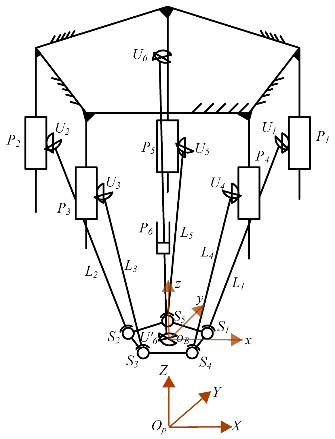
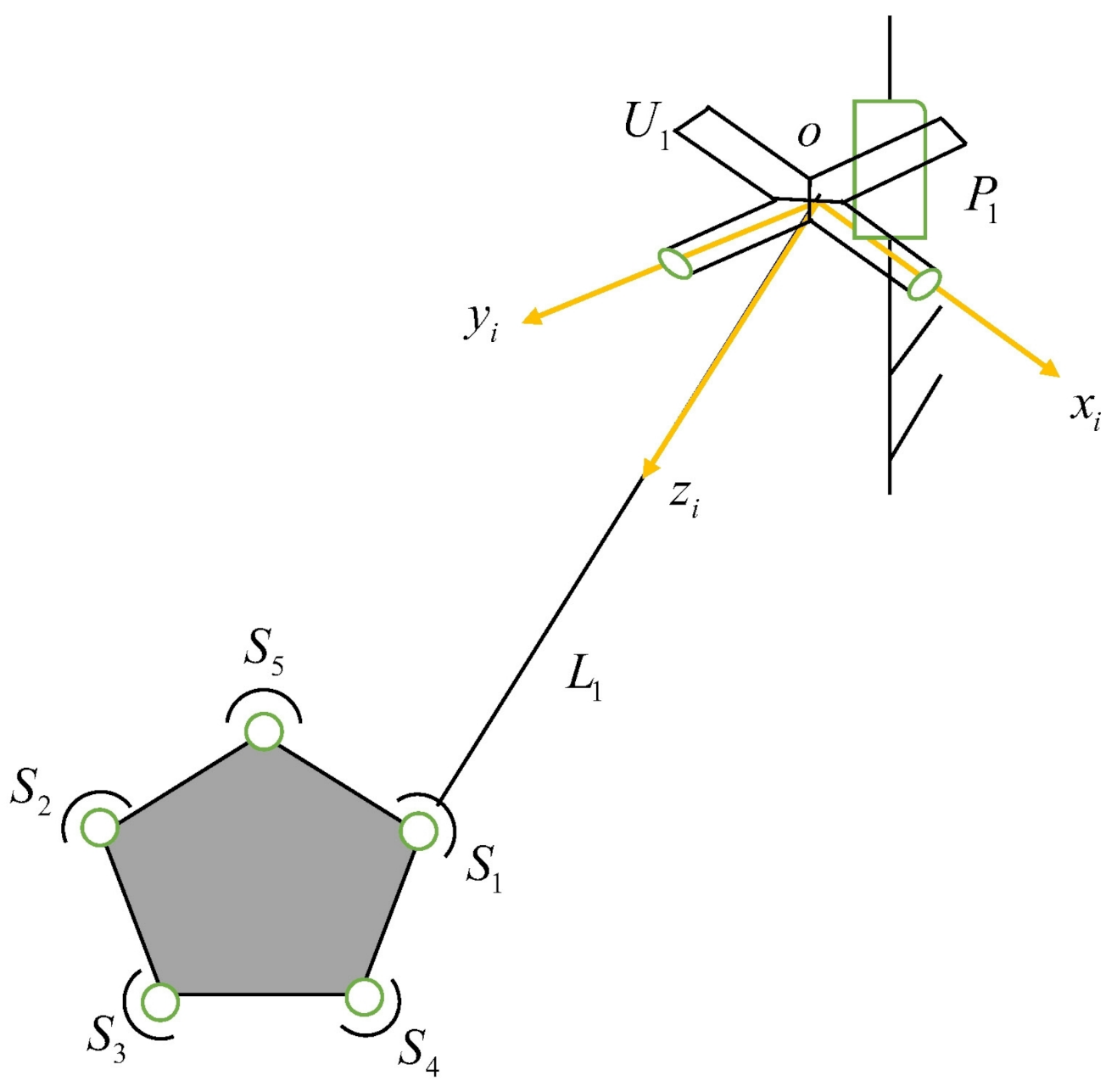
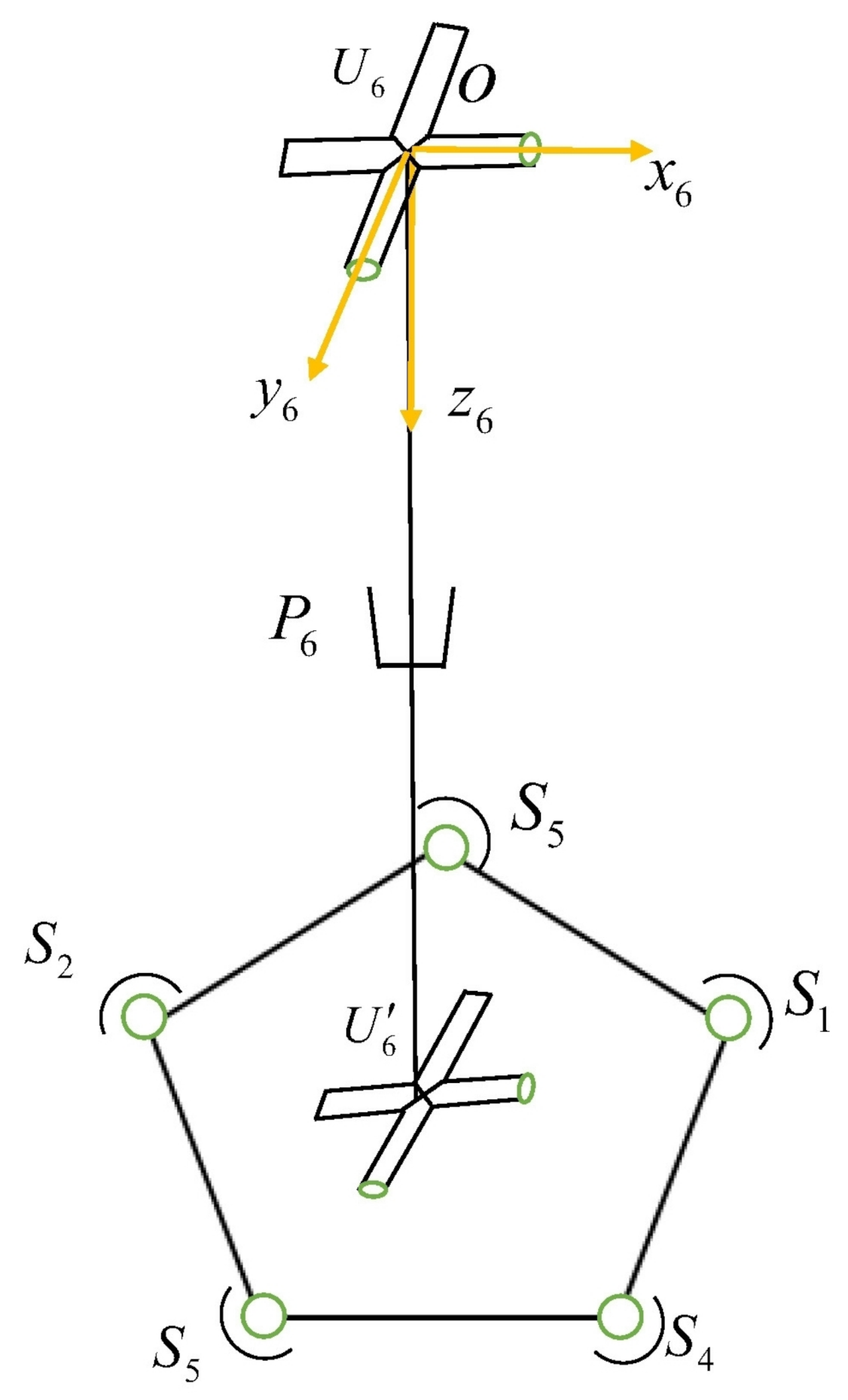
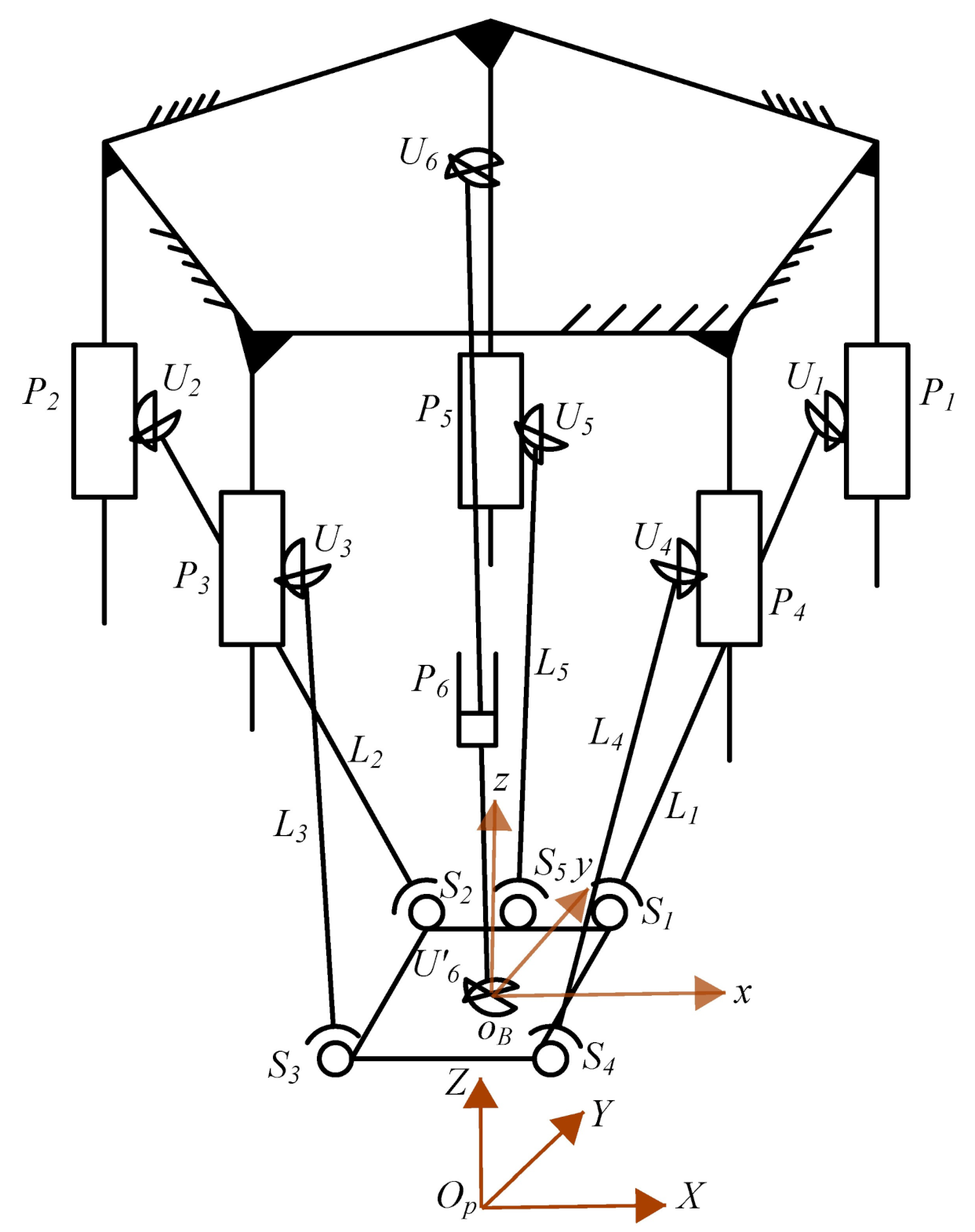
2.1. Design of the Primary Scheme

At present, 6-DOF Stewart platform [31] is used as the prototype for 5-DOF parallel mechanism. The minimum degrees of freedom of the 3D printer structure that meets multi-directional printing is 5–3 movements and two rotations. In the case of satisfying the degree of freedom requirement, the less degree of freedom of the mechanism, the simpler the mechanical structure, and the lower the manufacturing and control costs. Therefore, we choose to remove one of the six active limbs in the Stewart platform, and then rearrange the spatial positions of the five active limbs. However, at this time, there are only five driving modules, while the number of degrees of freedom of the moving platform is six. The number of driving modules is less than the degrees of freedom of the mechanism, which will cause the motion of the moving platform to be uncertain. The redundant degree of freedom of the moving platform is limited by adding a restraint limb between the moving platform and the fixed platform. At this time, the number of degrees of freedom of the moving platform is five, which meets the requirement of the degree of freedom.
As for the drive part of parallel mechanism, fixed-length link drive and telescopic link drive are the two most widely used ways at present. The driving mode of the mobile pair with a fixed-length link can greatly reduce the structural dimension of the link and avoid interference during the movement [29]. Therefore, we choose the driving method of the mobile pair with a fixed-length link in this paper. The five mobile pairs are used as actuators, which are symmetrically distributed in the shape of regular pentagons in space. The moving platform also adopts the symmetrical structure of the positive pentagon. As shown in Figure 1, the mechanism consists of five PUS limbs and one UPU limb. Five PUS limbs are called driving limbs, where P 1 P 5 are used as driving elements to represent the mobile pairs and are distributed on the corners of the positive pentagon, which are called sliders. U 1 U 5 represent Hook joints, connecting five sliders and five connecting links. S 1 S 5 represent the spherical hinges, connecting the moving platform and five connecting links. At the same time, the UPU limb is called the constrained limb and U 6 and U 6 represent Hook joints, which are fixed to the center of the regular pentagon and the center of the moving platform, respectively. P 6 represents the mobile pair, connecting Hook joints U 6 and U 6 .

2.2. Verification of the Primary Scheme

2.2.1. Verification of Degree of Freedom by Grubler–Kutzbach Formula

The number of degrees of freedom determines whether the designed mechanism meets the requirements, so the analysis of the degrees of freedom is particularly important. The traditional Grubler–Kutzbach method is relatively simple, it only depends on the number of components and kinematic pairs of the mechanism, and the degree of freedom of the mechanism can be obtained only through the most basic mathematical calculations. Therefore, this paper firstly uses Grubler–Kutzbach method to verify the degree of freedom of the mechanism. The main contents of Grubler–Kutzbach method are as follows:
In three-dimensional space, when a component is free before it is connected with other components by kinematic pairs. The n components including the frame have 6 ( n 1 ) degrees of freedom. When one component is connected to another component with a kinematic pair, the component is constrained to a certain extent and its degree of freedom is reduced. When the two components are connected by a kinematic pair with f i degrees of freedom, the degree of freedom of the original system is reduced by 6 f i due to increased constraints. When the number of kinematic pairs continues to increase to g, the degree of freedom of the system is reduced by ( 6 g i = 1 g f i )
At this time, the degree of freedom of the mechanism is
M = 6 ( n g 1 ) + i = 1 g f i
where M is the degree of freedom of the mechanism (Mobility); n is the total number of components of the mechanism; g is the number of kinematic pairs of the mechanism; f i is the number of degrees of freedom of the ith kinematic pair.
As shown in Figure 1, the mechanism is composed of one fixed platform, one moving platform, seven connecting links, and five sliders, so the total number of mechanism components is n = 14 . The mechanism has seven Hook joints, six mobile pairs, and five spherical hinges, so the number of moving pairs is g = 18 . The degree of freedom of each Hook joint is two, the degree of freedom of the mobile pair is one, the degree of freedom of the spherical hinges is three, and the sum of the degrees of freedom of the moving pair is i = 1 g f i = 2 × 7 + 1 × 6 + 3 × 5 = 35 , so
M = 6 ( n g 1 ) + i = 1 g f i = 6 × ( 14 18 1 ) + 35 = 5
That means the mechanism has five degrees of freedom, the five sliders are used as the driving part, and the mechanism can achieve a certain movement.

2.2.2. Verification of Degree of Freedom by Screw Theory

Traditional Grubler–Kutzbach method can only be calculated as five degrees of freedom of the mechanism, which is not clear about the specific situation of the degree of freedom. Therefore, after a long-term development, the idea of solving the degree of freedom of parallel mechanism by screw theory emerged. The degree of freedom of 5-PUS-UPU parallel mechanism is further analyzed by using screw theory. In screw theory, the screw is generally expressed as ( S ; S 0 ) or plücker coordinates ( a b c ; l m n ) [32]. S is the original part of the rotation and S 0 is the dual part of the rotation. The reciprocal product of two screws ( $ 1 = ( S 1 ; S 1 0 ) , $ 2 = ( S 2 ; S 2 0 ) ) is defined as the sum of the dot products after the exchange of the original and dual part
$ 1 $ 2 = S 1 · S 2 0 + S 2 · S 1 0
When the reciprocal product formed by $ 1 and $ 2 is 0:
$ 1 $ 2 = 0
They are reciprocal, and the screw $ 2 is called the reciprocal screw of $ 1 . Therefore, the reciprocal screw can be obtained based on the fact that the reciprocal product of the two screws is 0.
The parallel mechanism designed in this paper uses five identical PUS limbs as the active limbs and one UPU limb as the constrained limb. Now the center point of the Hook joint is set as the origin o, the directions of the two axes are the x-axis and the y-axis, respectively, and the z-axis is perpendicular to the x o y plane to establish a coordinate system, as shown in Figure 2.
The kinematic pairs on the active limbs are sequentially decomposed into single-degree-of-freedom motions, and the achievable motion of active limb 1 is expressed in a screw form [33]:
$ 1 = ( 0 0 0 ; l 1 m 1 n 1 ) $ 2 = ( 1 0 0 ; 0 0 0 ) $ 3 = ( 0 1 0 ; 0 0 0 ) $ 4 = ( 1 0 0 ; 0 m 4 0 ) $ 5 = ( 0 1 0 ; l 5 0 0 ) $ 6 = ( 0 0 1 ; 0 0 0 )
where l 1 , m 1 , n 1 , m 4 , l 5 represent coordinate parameters that are not zero, and $ 1 is the screw representation of moving pair P 1 ; $ 2 is the spiral representation of degree of freedom of rotation of Hook joint U 1 around x-axis; $ 3 is the screw representation of degree of freedom of rotation of Hook joint U 1 around y-axis; $ 4 is the screw representation of degree of freedom of rotation of spherical hinge S 1 around x-axis; $ 5 is the screw representation of the degree of rotation of spherical hinge S 1 about the y-axis, and $ 6 is the spiral representation of the degree of rotation of spherical hinge S 1 about the z-axis.
The screw system consisting of $ 1 , $ 2 , $ 3 , $ 4 , $ 5 , and $ 6 has been simplified to:
1 0 0 0 0 0 0 1 0 0 0 0 0 0 1 0 0 0 0 0 0 l 5 0 0 0 0 0 0 m 4 0 0 0 0 0 0 n 1
The twist of the active limb has a full rank, so there is no reciprocal screw. Similarly, the other four active limbs have the same analysis results. It can be seen that the five active limbs have no restriction on the moving platform [34].
When analyzing the constraint of the constraint limb to the moving platform, constrained limb coordinate system o 6 x 6 y 6 z 6 is established. Similarly, the center point of Hook joint is set as origin o, and the two axes of Hook joint are set as x 6 -axes and y 6 -axes respectively, and the z 6 axes are perpendicular to the plane of x 6 o 6 y 6 to establish coordinate system, as shown in Figure 3.
Then, the screw system of the restrained limb is represented as:
$ 1 = ( 1 0 0 ; 0 0 0 ) $ 2 = ( 0 1 0 ; 0 0 0 ) $ 3 = ( 0 0 0 ; l 3 m 3 n 3 ) $ 4 = ( 1 0 0 ; 0 m 4 0 ) $ 5 = ( 0 1 0 ; l 5 0 0 )
where l 3 , m 3 , n 3 , m 4 , l 5 represent coordinate parameters and are not 0.
The screw system consisting of $ 1 , $ 2 , $ 3 , $ 4 , and $ 5 has been simplified to:
1 0 0 0 0 0 0 1 0 0 0 0 0 0 0 l 5 0 0 0 0 0 0 m 4 0 0 0 0 0 0 n 3
Finally, the reciprocal screw of the constrained limb is: $ r = ( 0 0 0 ; 0 0 1 ) . From the physical meaning of the screw and the reciprocal screw, when the screw represents motion, the reciprocal screw represents constraints. That means the constraint limb gives the moving platform a constraint moment rotating around the z-axis, while the remaining degrees of freedom are unrestricted. That is, the moving platform can achieve the movement of five degrees of freedom—moving along the x-axis, y-axis, and z-axis and rotating around the x-axis and y-axis.

2.3. Singularity Analysis

Parallel mechanism has the characteristics of strong bearing capacity, large stiffness, and high motion accuracy. However, in practical application, it shows stiffness degradation, motion instability, bearing capacity reduction, and other phenomena when it is at some special positions, which is revealed in the experimental verification. In the study of this paper, the uncertainty of degree of freedom appears when the moving platform is directly above the zero point. The reduction of mechanism performance is not only related to the design, manufacture, and assembly of the mechanism but also closely related to the unique singularity and the dynamic stability of the singularity. The singularity of the mechanism generally refers to the situation that the inverse kinematics solution of the mechanism does not exist, the mechanism motion is unstable, and the driving force in the limb suddenly increases at some positions [35]. The analysis of singularity is the basis to verify the design and avoid the motion in singular space.
The essence of singularity of parallel mechanism is force screw failure of partial limbs acting on the moving platform. Based on this, the force of limbs acting on the moving platform is defined as line vector. The linear correlation between these line vectors is analyzed by using Grassmann line geometry method and the maximum linear independent number of these line vectors is defined as rank of line cluster.
The rank of the line cluster can be divided into 1 to 5 [36]. When the rank of the line cluster is 1, there is a line in the three-dimensional space. When the rank of a line cluster is 2, it includes two types of spatial distribution: (a) A pair of skew lines; (b) A flat pencil of lines. When the rank of the line cluster is 3, there are 4 kinds of spatial distribution: (a) A regulus; (b) All lines through a point; (c) The union of two flat pencils having a line in common but lying in distinct planes and with distinct centers; (d) All lines in a plane. When the rank of the line cluster is 4, the spatial distribution is four kinds: (a) Elliptic congruence; (b) Parabolic congruence; (c) Hyperbolic congruence; (d) Degenerate congruence. When the rank of the line cluster is 5, there are two spatial distributions: (a) Non singular complex: generated by five skew lines; (b) Singular complex: all the lines meeting one given line.
The singularity of this scheme occurs when the moving platform is parallel to the fixed platform and the moving platform is directly above the zero point; the force line vector extension lines of the five limbs intersect at one point, as shown in Figure 4. In this case, the singular form of the rank of the line cluster belongs to the (b) spatial distribution with rank 3 of the line cluster. It is the case that all lines go through a point. At this time, the rank of the five force line vectors is 3. In theory, for a compound screw system composed of force line vectors and couple-vectors, if the force line vectors are linearly independent of each other, and the couple-vectors are independent of each other, after the force line vectors are translated, the new force couple system composed of the resulting additional force couple and the original force couple system is also linearly independent. However, the specific research object of this paper is five force line vectors and a couple-vector. From the specific form of plücker coordinate, the rank of the composite screw system is equal to the rank of a directional vector matrix composed of five force line vectors plus one couple-vector rank [37]. Therefore, the rank of the five force line vectors is 3, plus the rank 1 of the couple-vector, so that the rank of the final composite screw system is 4. The corresponding physical meaning is that the movement of the moving platform along the X, Y, and Z axes and the rotation around the Z-axis are effectively constrained while the rotation around the X and Y axes is not limited, resulting in a singularity. This kind of singularity is called the "structural singularity" of the mechanism since both fixed and moving platforms are regular pentagons.

2.4. Scheme Improvement and Singularity Analysis

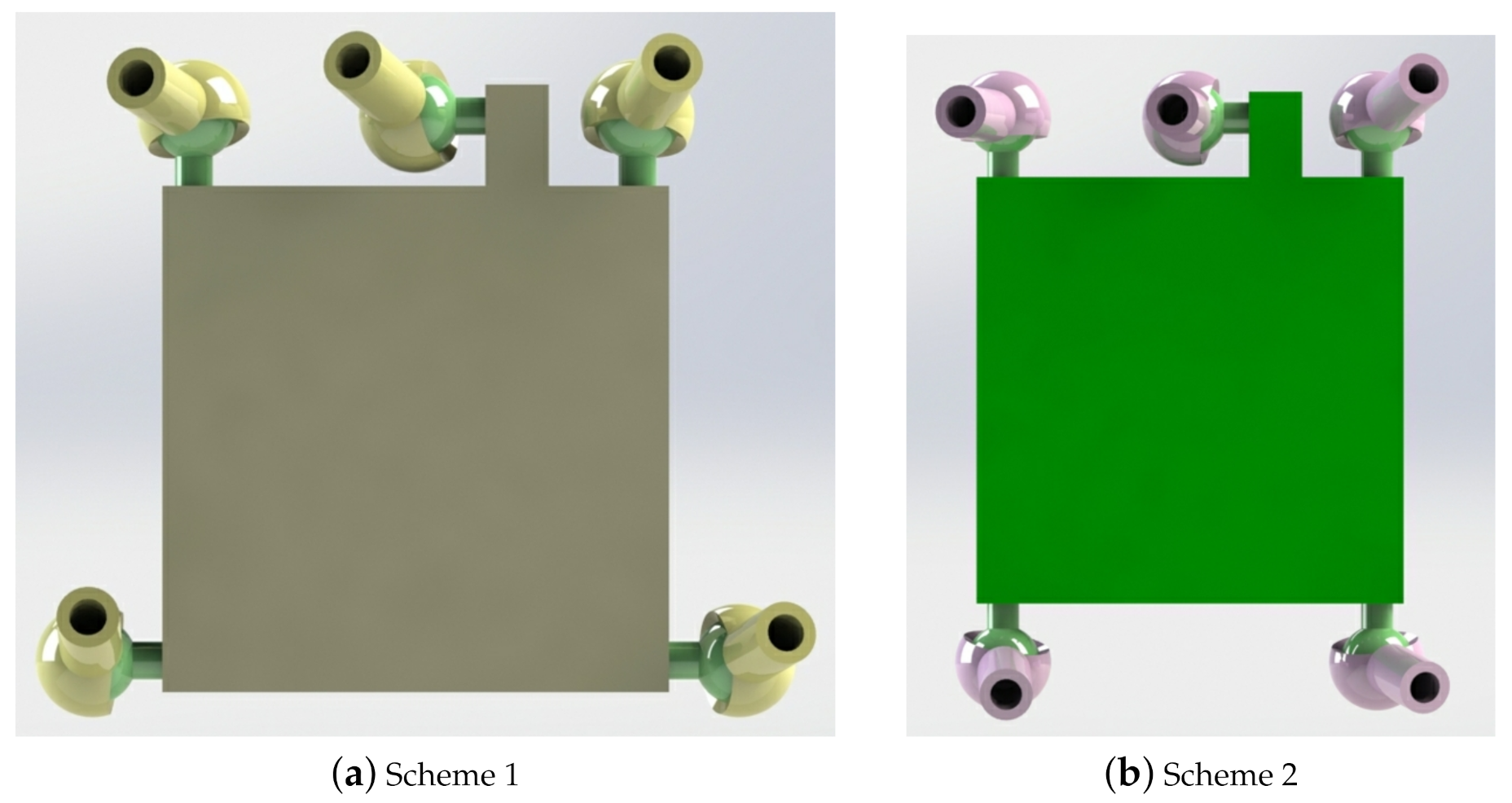
2.4.1. Scheme Improvement

Based on the singular defect caused by the same shape of fixed platform and moving platform in the preliminary scheme, the moving platform is changed from pentagon to quadrilateral. The mechanism sketch is shown in Figure 5.
In the improved scheme, the fixed platform also uses five mobile pairs as input and presents a positive pentagonal symmetrical distribution in space, while the moving platform uses a rectangular structure.

2.4.2. Singularity Analysis of Improved Parallel Mechanism

Singularity is an inherent property of parallel mechanism [38]. It is found that the improved parallel mechanism scheme still has singularity, which occurs at the position shown in Figure 6. At this time, the singularity of the line cluster rank belongs to the (b) spatial distribution of line cluster rank 4, which is parabolic congruence. The rank of the five force line vectors is 4, plus the rank of the constraining force couple; the final composite screw system has a rank of 5. The corresponding physical meaning is that after fixing five input sliders, the rotational freedom of the moving platform around the line connecting the spherical hinges S 1 and S 2 is not effectively constrained, and the singularity occurs. However, after carefully studying the position of the singularity occurring in the new scheme, it is found that due to the restriction of the spherical hinge angle in the parallel mechanism, the moving platform cannot move to this position. That means the position of the posture has exceeded the workspace of the moving platform. It can be seen from this that the improved parallel mechanism has no singularity in the workspace, and each position can be uniquely determined by the mechanism.

3. Kinematic Analysis

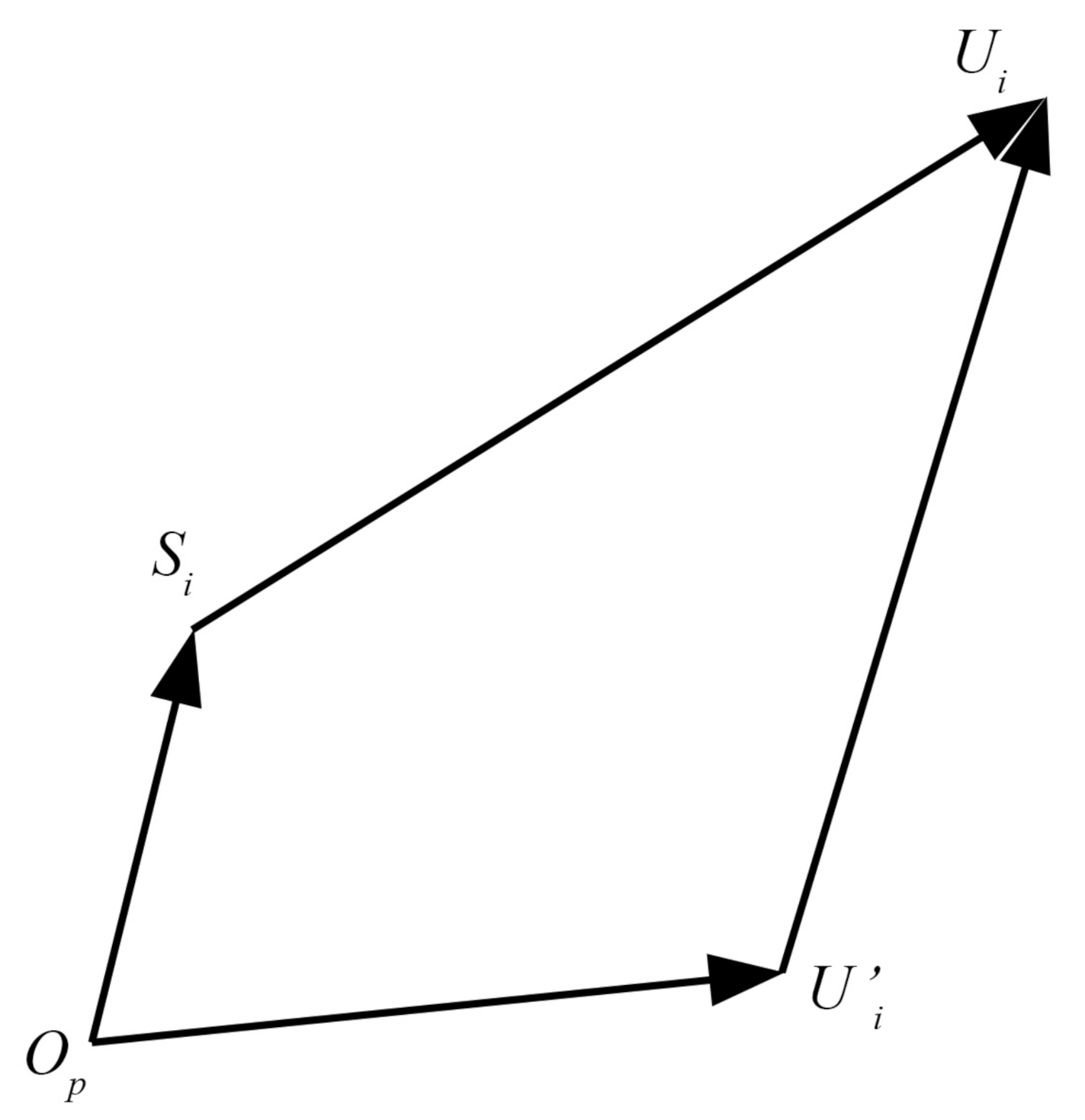
3.1. Establishment of Inverse Kinematics Equations

The coordinate systems of the mechanism consists of a moving coordinate system and a fixed coordinate system, as shown in Figure 5. The transformation matrix of the moving coordinate system o b x y z relative to the fixed coordinate system O p X Y Z is:
T = Trans ( x , y , z ) · Rot ( α , β , γ ) = 1 0 0 x 0 1 0 y 0 0 1 z 0 0 0 1 · cos β sin β sin α sin β cos α 0 0 cos α sin α 0 sin β cos β sin α cos β cos α 0 0 0 0 1 = cos β sin β sin α sin β cos α x 0 cos α sin α y sin β cos β sin α cos β cos α z 0 0 0 1
where x, y, and z represent the moving distance of the moving coordinate system along the X, Y, and Z axes of the fixed coordinate system respectively; α , β , and γ represent the rotating angles of the coordinate system along the X, Y, and Z axes of the fixed coordinate system respectively. Any point in the moving coordinate system can be converted into a specific coordinate value in the fixed coordinate system by
S i 1 = T s i 1
where S i is the coordinate value of five spherical hinges in the fixed coordinate system; s i is the coordinate value of five spherical hinges in the fixed coordinate system, and T is the coordinate transformation matrix.
The coordinate values of Hook joint U i (i = 1∼5) on the fixed platform and spherical hinge S i (i = 1∼5) on the moving platform in their respective coordinate systems are obtained through geometric relationship. Then the coordinate values of each point of the moving platform S i (i = 1∼5) in the fixed coordinate system can be obtained from Equations (7). During the movement of the moving platform, the link length remains unchanged. Any drive limb has the following closed-loop vector diagram shown in Figure 7:
Closed loop vector equation is established for Figure 7:
S i U i ¯ = O p U i ¯ + U i U i ¯ O p S i ¯ , i = 1 , 2 , 5
Among them, O p is the origin of fixed coordinate system, S i is the geometric center of spherical hinge on moving platform, U i is the geometric center of Hook joint fixed on slider, U i is the projection of U i on the plane of fixed coordinate system X O Y , and the modulus of the vector corresponds to the length from the center of the Hook joint to the center of the spherical hinge on each driving limb of L 1 L 5 , and this length is a fixed value during the movement of the moving platform.
L i = S i U i ¯ = ( X i U X i S ) 2 + ( Y i U Y i S ) 2 + ( Z i U Z i S ) 2
where X i U , Y i U , and Z i U represent the X, Y, and Z coordinates of U i ; X i S , Y i S , and Z i S represent the X, Y, and Z coordinates of S i .
The mapping equation for the position of five driving sliders and the posture coordinates of the moving platform is simplified as follows:
Z i U = Z i S ± L i 2 ( X i U X i S ) 2 + ( Y i U Y i S ) 2
Specific inverse equations can be obtained by incorporating coordinate values of U i and S i . Considering that the five sliders must be above the moving platform during the movement, the position inverse solution equation only takes positive signs.
The velocity equation of the mechanism is obtained by taking the derivative of Equation (11) with respect to time. Similarly, the acceleration equation of the mechanism is obtained by taking the derivative of the velocity equation with respect to time.
U ˙ 1 z U ˙ 2 z U ˙ 3 z U ˙ 4 z U ˙ 5 z = U 1 z x U 1 z y U 1 z z U 1 z α U 1 z β U 2 z x U 2 z y U 2 z z U 2 z α U 2 z β U 3 z x U 3 z y U 3 z z U 3 z α U 3 z β U 4 z x U 4 z y U 4 z z U 4 z α U 4 z β U 5 z x U 5 z y U 5 z z U 5 z α U 5 z β · x ˙ y ˙ z ˙ α ˙ β ˙
where U i z ( i = 1 , 2 , , 5 ) represents the coordinate of the Z axis of the five sliders in the static coordinate system.

3.2. Algorithm Simulation

In this mechanism, radius of outer circle of geometric center of Hook joint fixed on five sliders R = 135 mm. The distance from the spherical hinge to the geometric center of Hook joint L i = 205 mm. The coordinate values of the five spherical hinges rotation centers in the moving coordinate system are x 1 = 35 mm, y 1 = 51 mm, x 2 = 35 mm, y 2 = 51 mm, x 3 = 51 mm, y 3 = 35 mm, x 4 = 51 mm, y 4 = 35 mm, x 5 = 0 mm and y 5 = 51 mm. On the premise of x = 0 and β = 0 , the trajectory curve equation of the center point of the moving platform is:
α = π 3 + 1 30 π t , ( 0 < t < 10 ) y = 50 cos α z = 50 sin α
The geometric center target track of the moving platform is shown Figure 8.
The position change trajectories of the five sliders corresponding to this condition are obtained by inverse position solution formula as shown in Figure 9. The simulation results of the position curve show that the position change curves of the five sliders on the ball screw can be obtained by inverse position solution equation as long as the motion path of the moving platform is known, which lays a foundation for the control of the mechanism.
The velocity curves of the five sliders under this condition are obtained by taking the derivative of the inverse position equations with respect to time, as shown in Figure 10.
The acceleration curves of the five sliders under this condition are obtained by taking the second derivative of the inverse position equations, as shown in Figure 11.
The acceleration simulation results of five sliders show that the position, speed, and acceleration images of the sliders correspond to each other, and the absolute value of acceleration increases when the slope of the speed curve increases. The maximum absolute acceleration of the five sliders is 0.47 mm/s 2 , and this position is the end of the curve. The larger acceleration value is caused by the smaller angle between the fifth limb and the X O Y plane of the fixed coordinate system. If the movement continues according to this trend, the fifth limb will be parallel to the fixed platform, and a singularity will occur. Therefore, when planning the target curve of the moving platform, the workspace of the mechanism should be fully considered and the target curve should be strictly controlled within the workspace. The simplest way is to ensure the position of five sliders above the moving platform. On this basis, the speed and acceleration values of the five sliders are analyzed to provide the basis for motor drive control in the later stage.

4. Workspace Analysis

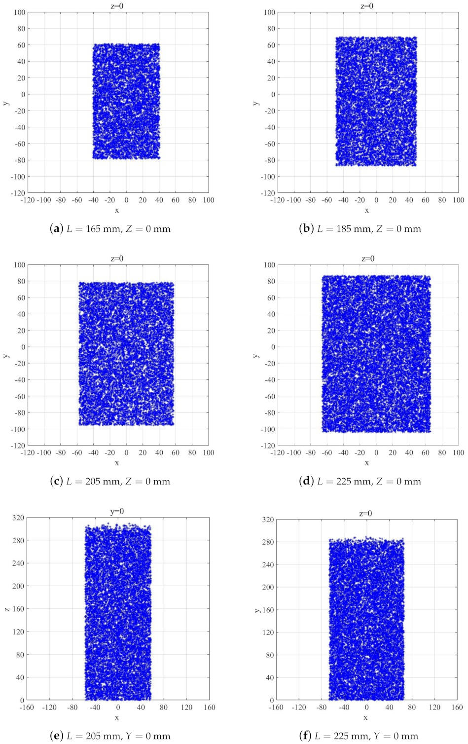
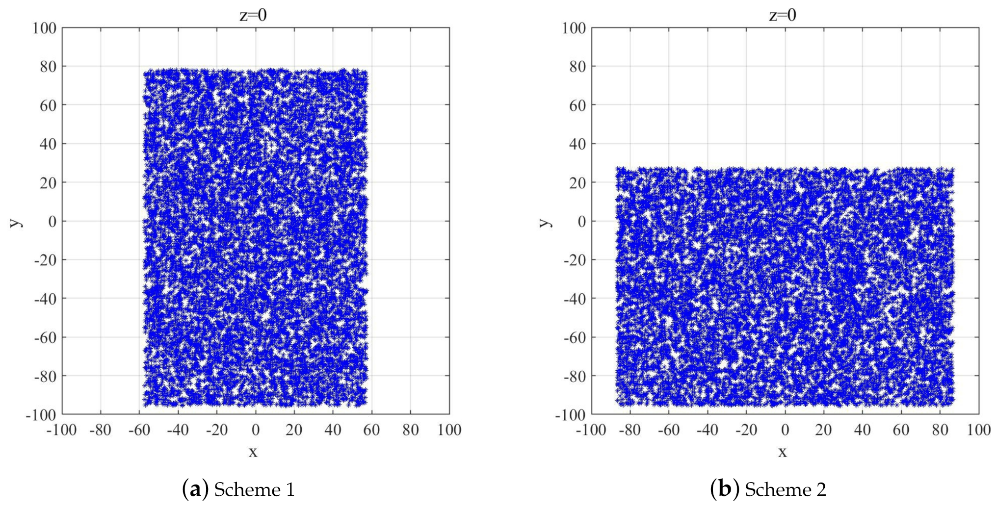
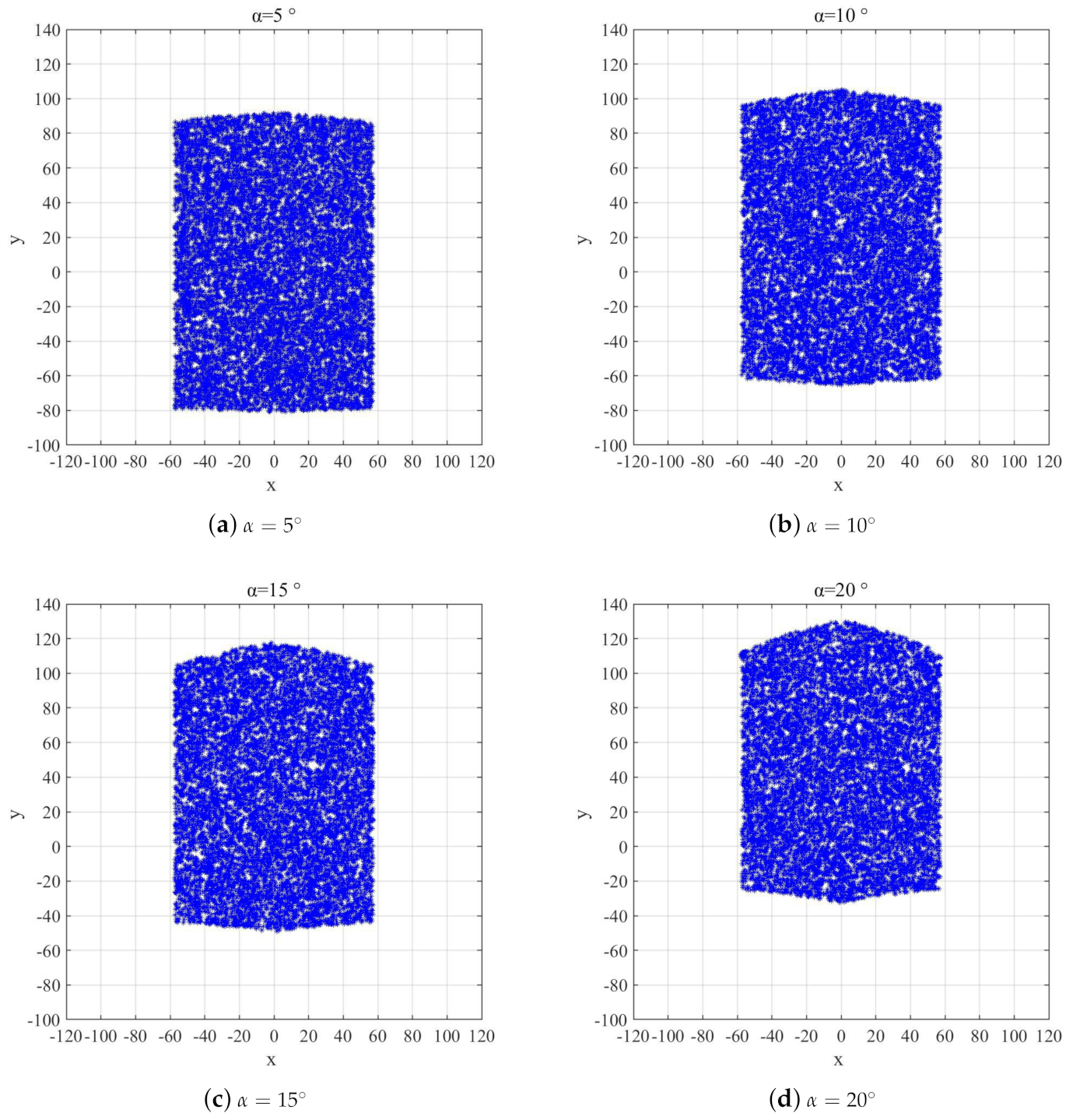
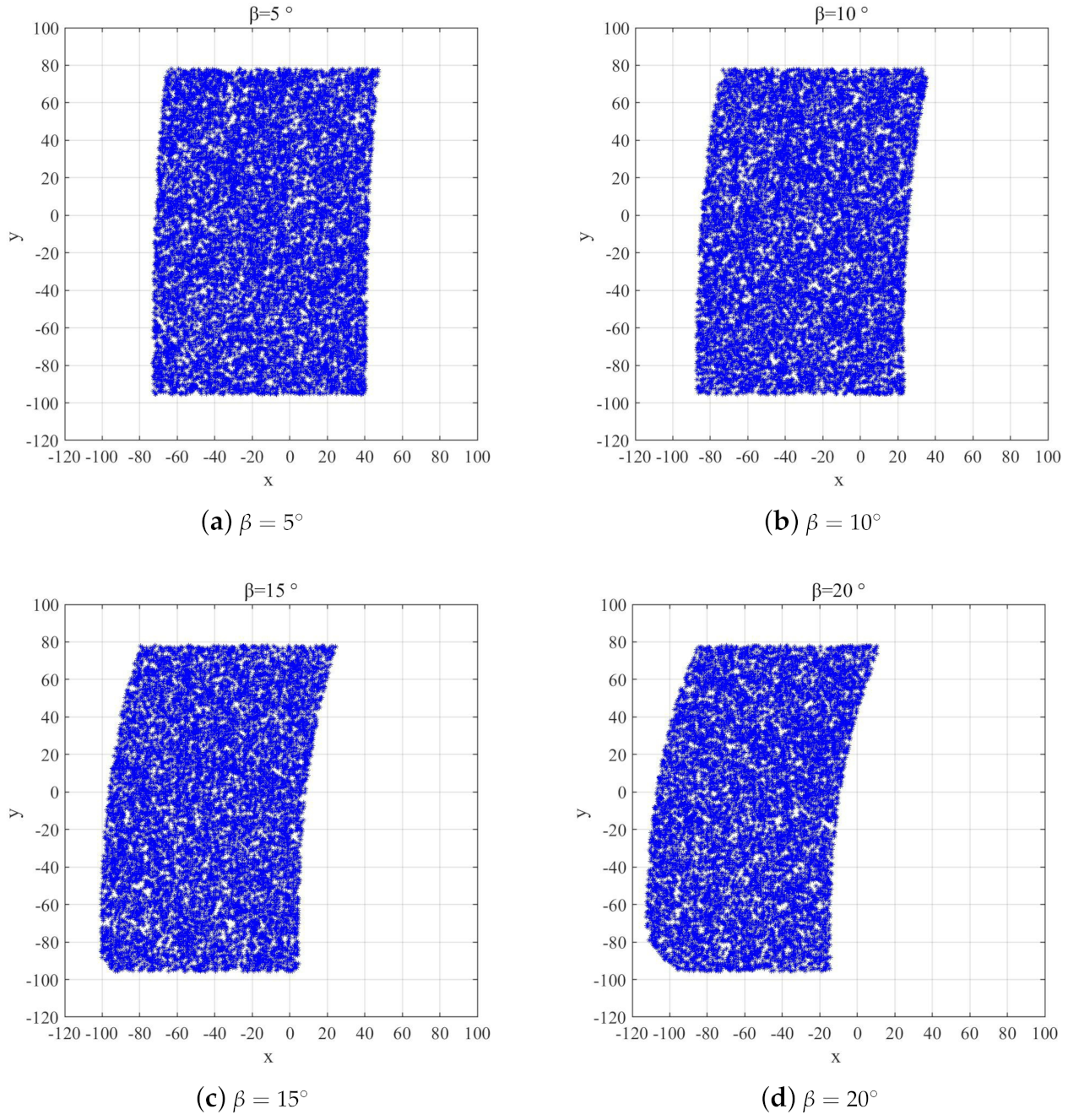
4.1. Influencing Factors of Workspace

The main factors that affect the workspace of parallel robot are:
(1) The limitation of the length of link. The link lengths of each limb are not random and must be limited to a certain range. When the length of the link is the minimum, the moving platform and the five limbs are in the same plane, and the mechanism has a singularity. When the length of the link is the maximum, the moving platform and the fixed platform coincide, the five sliders are located at the top of the lead screw, and the whole mechanism is locked.
(2) Limit of slider stroke. The influence of slider stroke range on workspace is mainly concentrated on Z dimension of workspace.
(3) The limitation of the position and angle of the spherical hinge. Because the movement range of the spherical hinge is in a certain range, the change of the position of the spherical hinge arrangement will change the position where the spherical hinge reaches the limit.
(4) Limit of link interference. In the actual prototype, each link has a certain size, so interference should be avoided.

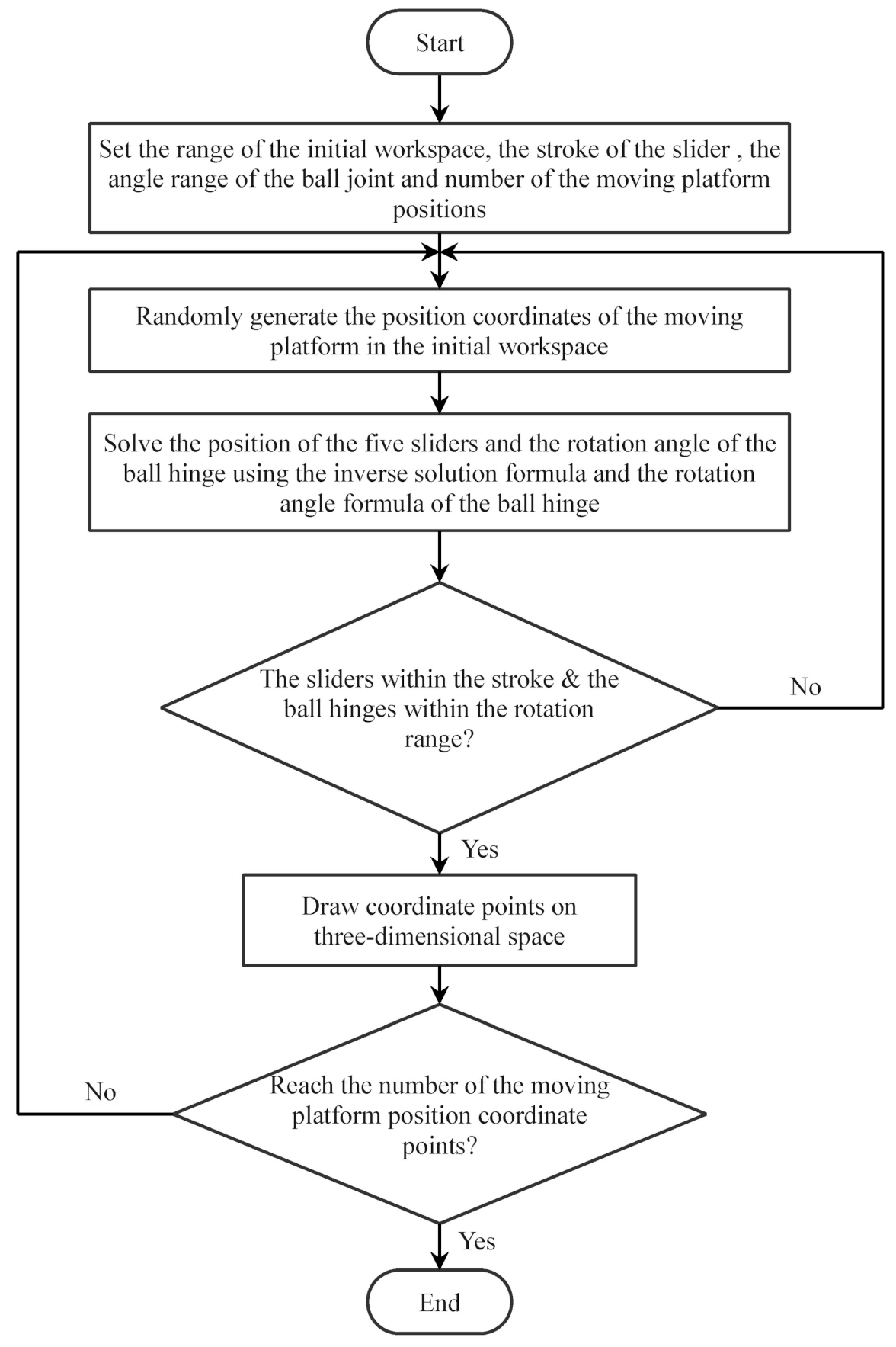
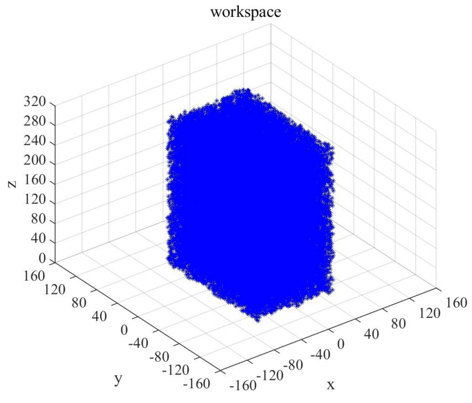
4.2. Monte Carlo Method

Monte Carlo method is based on the idea of random sampling to solve mathematical problems. The flowchart of solving mechanism workspace by Monte Carlo method is shown in Figure 12. The analysis process is as follows:
  • The random function is used to traverse the value in the initially set workspace.
  • These values are introduced into the inverse kinematics solution Equation (11) to obtain the variable values of each kinematic pair.
  • Record the corresponding traverse points of each motion pair in the workspace. These recorded traverse points are the points that the geometric center of the moving platform can reach, and finally constitute the three-dimensional point cloud map of the workspace.

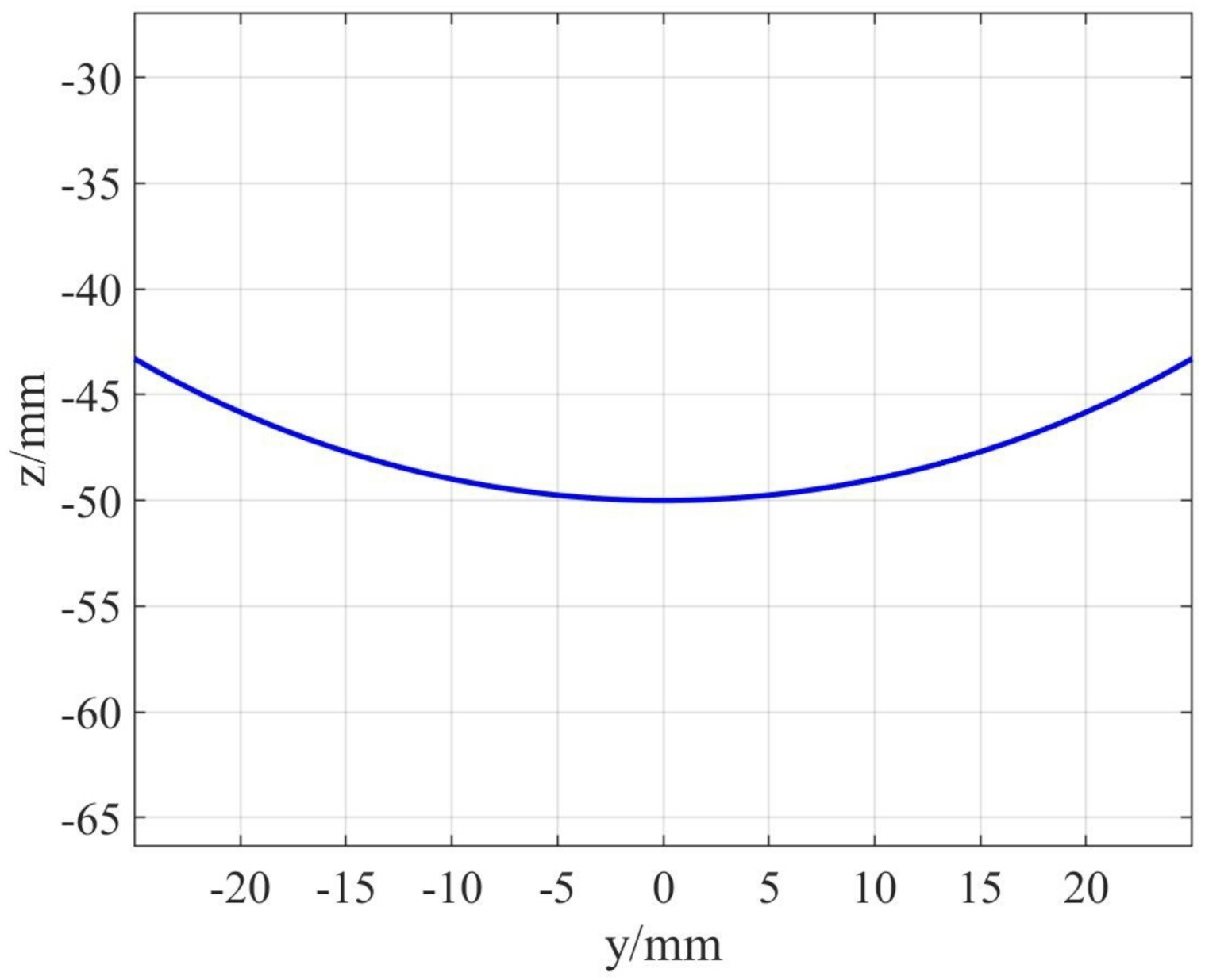
4.3. Algorithm Simulation of Optimal Workspace
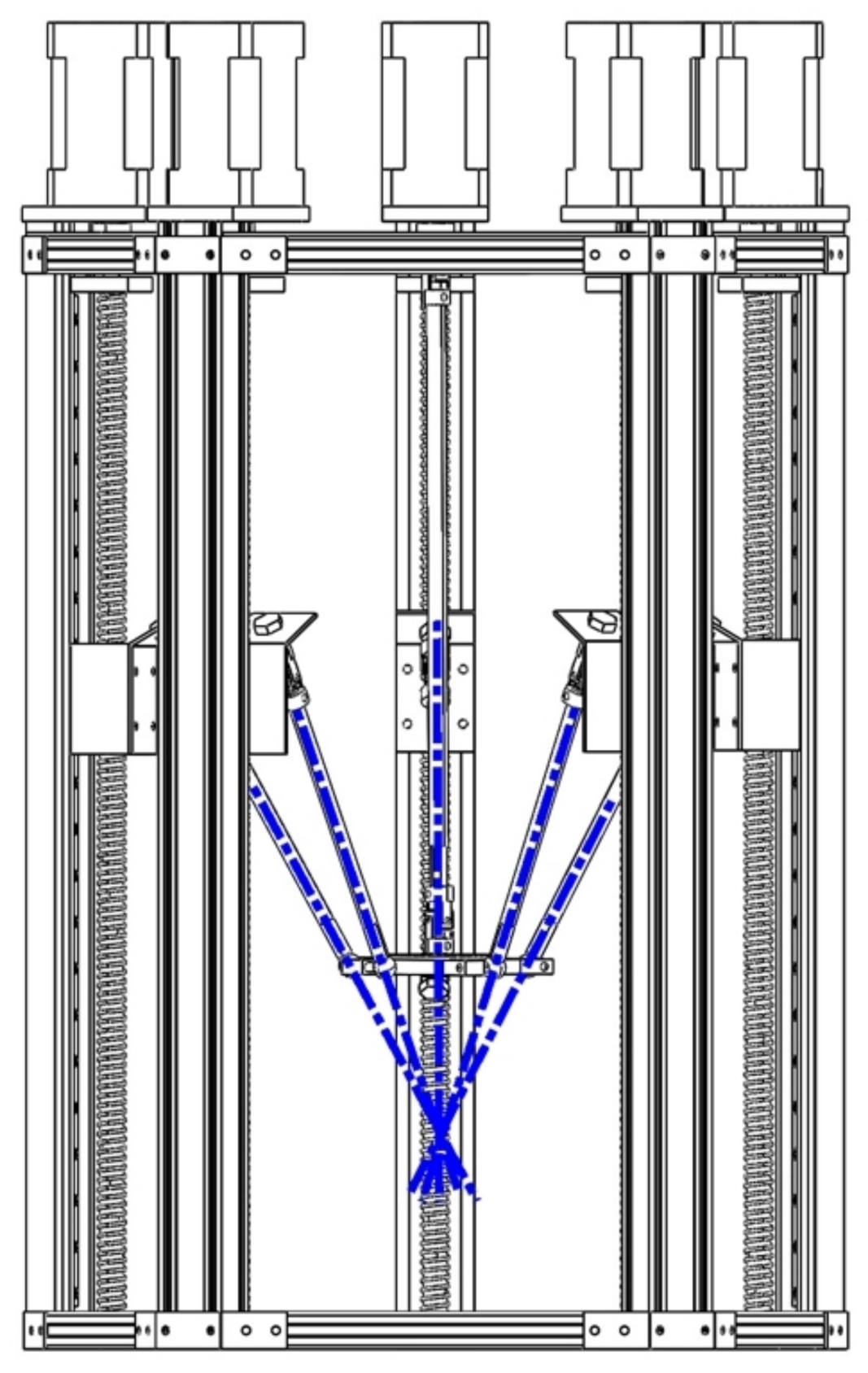
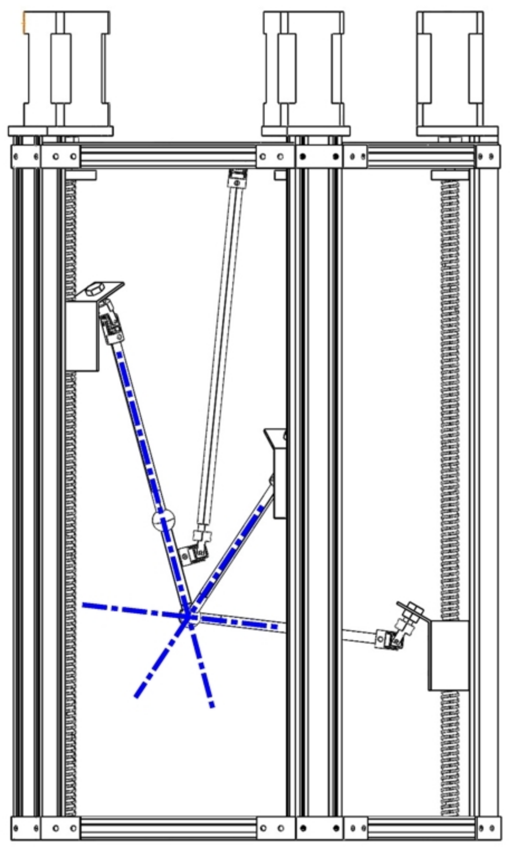
(1) Based on the influencing factors of workspace, the simulation parameters are changed to obtain the optimal workspace. The parameters are set as follows: the geometric centers of Hook joints on sliders are evenly distributed on the circle with radius R = 135 mm. Since the length of link affects the size of workspace, the length of five driving links is set as L = 165 mm, 185 mm, 205 mm, and 225 mm respectively, and the projection of workspace on the X O Y plane is shown in Figure 13.
From the comparison of Figure 13a–d, it can be seen that when the length of the link is changed from 165 mm to 205 mm, the projection of the three-dimensional workspace on the X O Y plane is significantly larger, but there is no obvious change from 205 mm to 225 mm. Figure 13e,f show the projection of the three-dimensional workspace on the X O Z plane when the α , β , and Y coordinates of the moving platform are all zero. After comparison, it is found that when L = 205 mm, the workspace has a better Z direction space. Therefore, we choose the link length of the limb to be 205 mm.
(2) After determining the length of the link L = 205 mm, the position of spherical hinge is optimized as shown in Figure 14, and the simulation result is shown in Figure 15.
When the length of the link and distribution radius of the Hook hinge are the same, and the spherical hinge is distributed according to Figure 14a, the projected area of the working space on the X O Y plane is 120 mm × 180 mm. When the spherical hinge is arranged according to Figure 14b, the projection area of the corresponding workspace in the X O Y plane is 160 mm × 120 mm, and the workspace is heavily biased to the negative direction of the Y axis, as shown in Figure 15b. Comparing the two schemes of spherical hinge, it is found that Scheme 1 (Figure 14a) has better isotropy in the workspace of X O Y plane, so this scheme will be adopted in the subsequent mechanism construction, and the previous chapters are based on the analysis of this solution.
(3) Fixed posture workspace
As an important form of workspace, fixed posture workspace studies the size of workspace when the moving platform is in a fixed posture. When α equals 5 , 10 , 15 and 20 , the fixed posture workspace is analyzed to study the influence of single posture angle on workspace. The results are shown in Figure 16.
Similarly, when β changes from 5 to 20 , the change in the fixed posture workspace is shown in Figure 17.
Finally, when both two posture angles are 0 , the size of the three-dimensional workspace is studied on the basis of the optimized length of the link and the position of the spherical hinge. The results are shown in Figure 18.
From Figure 16 and Figure 17, we can see that the 5-DOF parallel mechanism consists of two degrees of freedom of rotation, and the size of the two posture angles affects the size of the workspace, showing a general rule that the size of fixed posture workspace decreases with the increase of the posture angle and deviates from one direction of the coordinate axis. As to whether any variable attitude curve in space is within the workspace, we can reverse the kinematics of the subdivision points of the target curve to judge if the position of the sliders and the angle of spherical hinges corresponding to each subdivision point are within the range of motion.
The overlapping part of the simulation results of the fixed posture workspace satisfies the two cases, so according to the symmetry and superposition of the simulation results of α and β , the workspace size of the mechanism is 80 mm × 150 mm × 300 mm, when α and β are in the range of ± 5 . It is known from Figure 18 that when α = 0 and β = 0 , the size of the fixed posture workspace is 120 mm × 175 mm × 300 mm.

5. Experiment

The whole prototype is made of profiles with side length of 20 mm, and the lead screw module and profiles are connected by connecting plates. The whole 5-DOF parallel mechanism is composed of moving platform, upper and lower plates, ball screws, driving limbs, restraining limb, connecting plates, Hook joints, and spherical hinges. The lower plate in this paper is also called fixed platform. The 3D model and physical model are shown in Figure 19.
The diameter of the link is 8 mm, the length of the link is 205 mm; Diameter, lead, and effective stroke of ball screw are 16 mm, 5 mm, and 205 mm respectively; the base size of the moving platform is a square with a side length equal to 80 mm, and the coordinates of the center positions of the five spherical hinges are ( 35 , 51 ) , ( 35 , 51 ) , ( 51 , 35 ) , ( 51 , 35 ) , ( 0 , 51 ) ; the slider is connected to the Hook joint on the driving limb through the inclined plate, and the angle between the two planes of the inclined plate is 120 . In addition, the center points of five Hook joints connected with the slider are evenly distributed on a circle with a radius of 135 mm.
In order to check the degree of freedom of the mechanism and measure the motion accuracy of the moving platform actuator, the posture angles of the moving platform are now set to α = 0 , β = 0 and α = 0 , β = 5 . We fixed a pencil on the moving platform, and the axis of the pencil is required to be perpendicular to the plane of the drawing paper and a circle with a radius of 30 mm is drawn to verify the space motion function of the device. The track of the circle is planned and the reference speed of the moving platform is 10 mm/s.
During the experiment, the tip of the pen starts from the coordinate origin o. Firstly, the moving platform moves 5 mm in the positive direction of Z-axis, then moves to the right first above point A. The moving platform moves 5 mm in the negative direction of Z axis and the pen tip falls at point A. Then, go through B , C , D counterclockwise and back to point A. Finally, the moving platform moves up, the pen tip leaves the paper, and the experiment is completed. Among them, when drawing a circle with the posture angle α = 0 and β = 5 and the moving platform moves from directly above the origin to directly above point A, not only does the distance change but also β changes from 0 to 5 during this process. From this, the rotational freedom of the parallel mechanism can be verified.
The experimental results of drawing a circle in two situations with posture angles α = 0 , β = 0 and α = 0 , β = 5 are shown in Figure 20.
The coincidence point A of the circular trajectory can indicate that the trajectory of the parallel mechanism has good coincidence, and the successful drawing of circles in two cases of α = 0 , β = 0 and α = 0 , β = 5 illustrates the mechanism meets the design requirements of three-dimensional movement and two-dimensional rotation freedom. Due to the gap of hook joint and spherical hinge and the error of connecting link length, the motion error of moving platform is large. When the posture angle is α = 0 and β = 0 , the roundness error of the circle is 2 mm, and when the posture angle is α = 0 and β = 5 , the roundness error of the circle is 1.5 mm. How to further improve the motion accuracy of the moving platform is worthy of further study in the next step.

6. Conclusions

(1)
In this paper, based on the requirement of multi-dimensional 3D printing, two 5PUS-UPU parallel mechanisms with five degrees of freedom are designed, and their degrees of freedom are analyzed by using Grubler–Kutzbach and the screw theory. Based on the singularity analysis, the optimal scheme was determined in the two schemes.
(2)
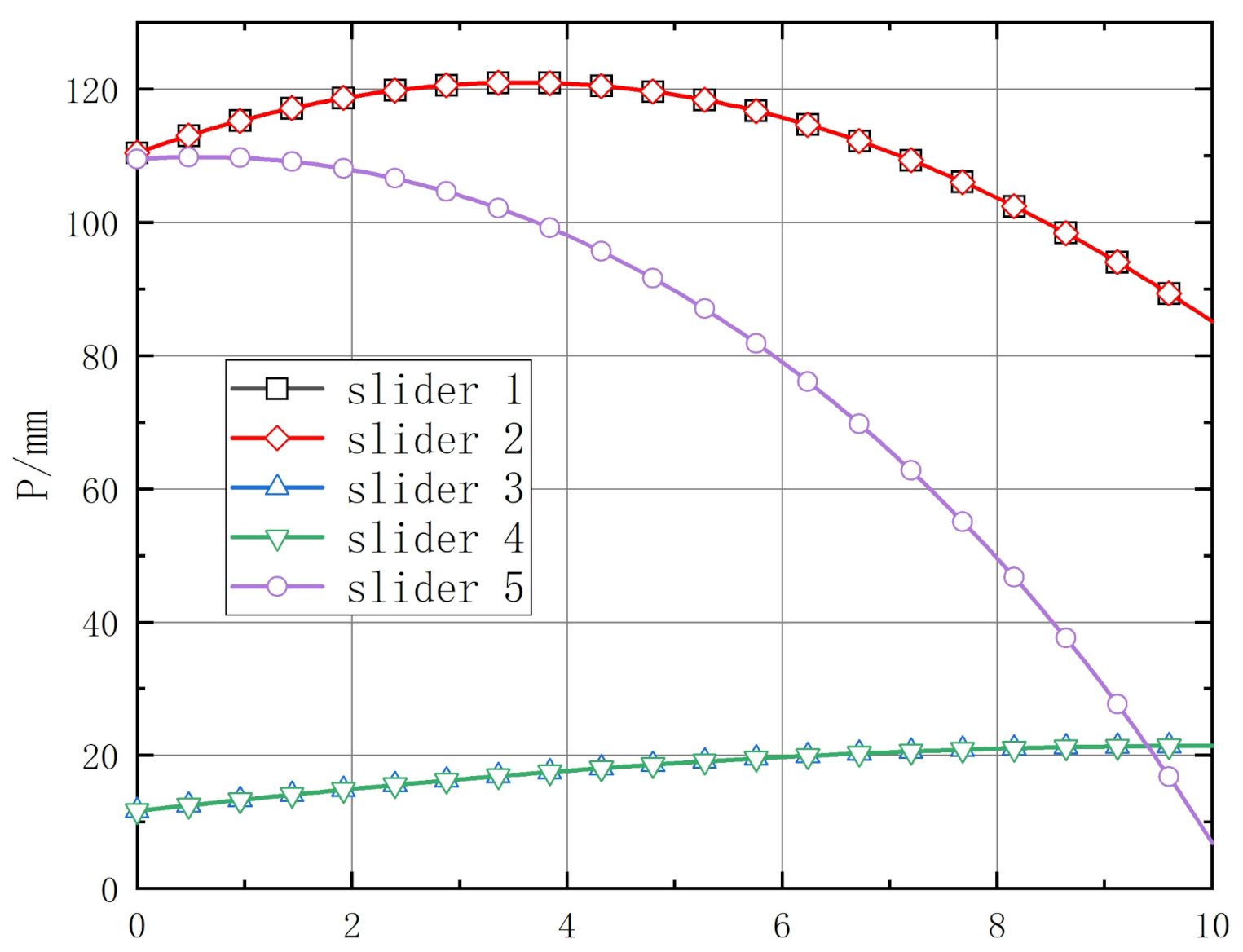
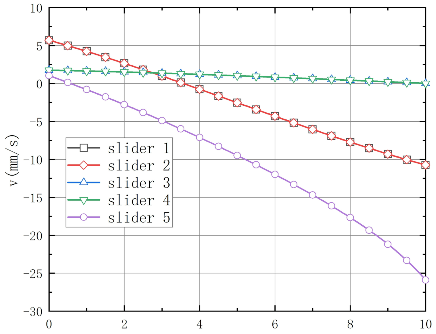
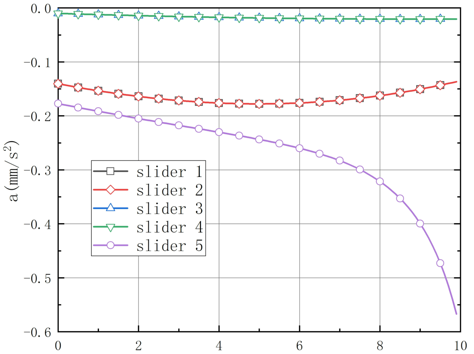
The coordinate system and coordinate transformation matrix are established for the optimal scheme. Based on the idea of inverse kinematics solution, the inverse position equation is established. The working condition that can reflect the 5-DOF movement of the mechanism is designed, and the position analysis, speed analysis, and acceleration analysis of the working condition are carried out.
(3)
Monte Carlo method is applied to analyze the workspace of the mechanism and to study the influencing factors of the workspace. Among the many influencing factors in the workspace, two factors are chosen: the length of the link and the position of the spherical hinge. The mechanism is optimized to obtain the optimal link length of 205 mm and the optimal position of the spherical hinge. It is concluded that the workspace size is 120 mm × 175 mm × 300 mm when the fixed posture is α = 0 and β = 0 , and 80 mm × 150 mm × 300 mm when α and β are within ± 5 .
(4)
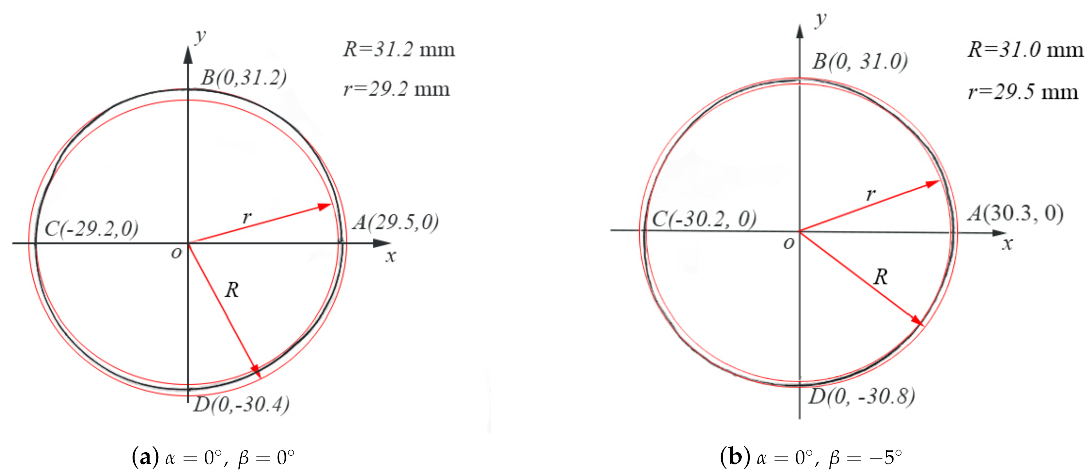
Design the experiment, set the posture angle of the moving platform in α = 0 , β = 0 and α = 0 , β = 5 , use a pencil replace the printing nozzle to draw a circle. By drawing the circular trajectory, it can be concluded that the mechanism meets the design requirements for the freedom of three-dimensional movement and two-dimensional rotation.
(5)
In the experimental analysis, although the experimental results basically meet the design requirements, the kinematic accuracy of the mechanism is low due to the gap of hook joint and spherical hinge and the error of connecting link length. Therefore, how to further improve the motion accuracy of the mechanism will be the focus of the next work.

Author Contributions

Conceptualization, J.L. and Y.W.; data curation, Y.W. and C.L.; formal analysis, Y.W., C.L. and J.L.; funding acquisition, J.L.; investigation, Y.W. and C.L.; methodology, Y.W. and J.L.; project administration, Y.W. and C.L.; resources, J.L.; software, Y.W. and C.L.; supervision, J.L. and Y.W.; validation, J.L.; writing—original draft, Y.W. and C.L.; writing—review and editing, Y.W. and C.L. All authors have read and agreed to the published version of the manuscript.

Funding

This research received no external funding.

Institutional Review Board Statement

Not applicable.

Informed Consent Statement

Not applicable.

Data Availability Statement

The data are contained within the article.

Conflicts of Interest

The authors declare no conflict of interest.

References

  1. Liu, J.; Tian, Y.; Gao, F. A novel six-legged walking machine tool for in-situ operations. Front. Mech. Eng. 2020, 15, 351–364. [Google Scholar] [CrossRef]
  2. Zhang, D.S.; Xu, Y.D.; Yao, J.T.; Zhao, Y.S. Analysis and Optimization of a Spatial Parallel Mechanism for a New 5-DOF Hybrid Serial-Parallel Manipulator. Chin. J. Mech. Eng. 2018, 31, 54. [Google Scholar] [CrossRef] [Green Version]
  3. Zhou, K.; Mao, D.; Tao, Z. Kinematic Analysis and Application Research on a High-Speed Travelling Double Four-Rod Spatial Parallel Mechanism. Int. J. Adv. Manuf. Technol. 2002, 19, 873–878. [Google Scholar] [CrossRef]
  4. Lu, S.; Li, Y.; Ding, B. Kinematics and dynamics analysis of the 3PUS-PRU parallel mechanism module designed for a novel 6-DOF gantry hybrid machine tool. J. Mech. Sci. Technol. 2020, 34, 345–357. [Google Scholar] [CrossRef]
  5. Pakzad, S.; Akhbari, S.; Mahboubkhah, M. Kinematic and dynamic analyses of a novel 4-DOF parallel mechanism. J. Braz. Soc. Mech. Sci. Eng. 2019, 41, 561. [Google Scholar] [CrossRef]
  6. Zhang, G.; Guo, J.; Hou, Y.; Zeng, D. Analysis of the PU-2UPS antenna parallel mechanism. J. Mech. Sci. Technol. 2021, 35, 717–728. [Google Scholar] [CrossRef]
  7. Lim, H.; Lee, S.H.; So, B.R.; Yi, B.J. Design of a new 6-DOF parallel mechanism with a suspended platform. Int. J. Control Autom. Syst. 2015, 13, 942–950. [Google Scholar] [CrossRef]
  8. Seo, T.W.; In, W.; Kim, J. A new planar 3-DOF parallel mechanism with continuous 360-degree rotational capability. J. Mech. Sci. Technol. 2009, 23, 3088–3094. [Google Scholar] [CrossRef]
  9. Kuo, Y.L.; Cleghorn, W.L.; Behdinan, K. Stress-based finite element method for Euler-Bernoulli beams. Trans.-Can. Soc. Mech. Eng. 2007, 30, 1–6. [Google Scholar] [CrossRef]
  10. Taghirad, H.D. Parallel Robots: Mechanics and Control; CRC Press: Boca Raton, FL, USA, 2013. [Google Scholar]
  11. Dwivedy, S.K.; Eberhard, P. Dynamic analysis of flexible manipulators, a literature review—ScienceDirect. Mech. Mach. Theory 2006, 41, 749–777. [Google Scholar] [CrossRef]
  12. Kurazume, R.; Hasegawa, T. A new index of serial-link manipulator performance combining dynamic manipulability and manipulating force ellipsoids. IEEE Trans. Robot. 2006, 22, 1022–1028. [Google Scholar] [CrossRef]
  13. Wang, L.; Fang, Y.; Qu, H.; Li, L. Design and analysis of novel 2R1T generalized parallel mechanisms with large rotational angles. Mech. Mach. Theory 2020, 150, 103879. [Google Scholar] [CrossRef]
  14. Yar, A.; Kiper, G.; Dede, M.C. Kinematic design of a non-parasitic 2R1T parallel mechanism with remote center of motion to be used in minimally invasive surgery applications. Mech. Mach. Theory 2020, 153, 104013. [Google Scholar] [CrossRef]
  15. Liping, W.; Huayang, X.; Liwen, G.; Yu, Z. A novel 3-PUU parallel mechanism and its kinematic issues. Robot. Comput. Integr. Manuf. 2016, 42, 86–102. [Google Scholar] [CrossRef]
  16. Du, X.; Li, Y.; Wang, P.; Ma, Z.; Wu, C.Y. Design and optimization of solar tracker with U-PRU-PUS parallel mechanism. Mech. Mach. Theory 2021, 155, 104107. [Google Scholar] [CrossRef]
  17. Chen, Z.; Li, M.; Kong, X.; Zhao, C. Kinematics analysis of a novel 2R1T 3-PUU parallel mechanism with multiple rotation centers. Mech. Mach. Theory 2020, 152, 103938. [Google Scholar] [CrossRef]
  18. Russo, M.; Herrero, S.; Altuzarra, O.; Ceccarelli, M. Kinematic analysis and multi-objective optimization of a 3-UPR parallel mechanism for a robotic leg. Mech. Mach. Theory 2018, 120, 192–202. [Google Scholar] [CrossRef]
  19. Br, G.F.; Wei, G. Kinematic analysis of a pentapod robot. J. Geom. Graph. 2006, 10, 173–182. [Google Scholar]
  20. Chen, X.; Liang, X.; Deng, Y.; Wang, Q. Rigid Dynamic Model and Analysis of 5-DOF Parallel Mechanism. Int. J. Adv. Robot. Syst. 2015, 12, 108. [Google Scholar] [CrossRef] [Green Version]
  21. Piccin, O.; Bayle, B.; Maurin, B.; Mathelin, M.D. Kinematic modeling of a 5-DOF parallel mechanism for semi-spherical workspace. Mech. Mach. Theory 2009, 44, 1485–1496. [Google Scholar] [CrossRef]
  22. Wang, J.; Gosselin, C.M. Singularity Loci of a Special Class of Spherical 3-DOF Parallel Mechanisms With Prismatic Actuators. Asme J. Mech. Des. 2004, 126, 319–326. [Google Scholar] [CrossRef]
  23. Gallardo-Alvarado, J.; Rico-Martínez, J.M.; Alici, G. Kinematics and singularity analyses of a 4-dof parallel manipulator using screw theory. Mech. Mach. Theory 2006, 41, 1048–1061. [Google Scholar] [CrossRef]
  24. Guo, S.; Wang, C.; Qu, H.; Fang, Y. A novel 4-RRCR parallel mechanism based on screw theory and its kinematics analysis. Proc. Inst. Mech. Eng. Part C J. Mech. Eng. Ence 2013, 227, 2039–2048. [Google Scholar] [CrossRef]
  25. Thomas, M.J.; Joy, M.L.; Sudheer, A.P. Kinematic and Dynamic Analysis of a 3-PRUS Spatial Parallel Manipulator. Chin. J. Mech. Eng. 2020, 33, 13. [Google Scholar] [CrossRef] [Green Version]
  26. Wolf, A.; Ottaviano, E.; Shoham, M.; Ceccarelli, M. Application of line geometry and linear complex approximation to singularity analysis of the 3-DOF CaPaMan parallel manipulator. Mech. Mach. Theory 2004, 39, 75–95. [Google Scholar] [CrossRef]
  27. Tian, C.; Fang, Y.; Ge, Q. Design and analysis of a partially decoupled generalized parallel mechanism for 3T1R motion. Mech. Mach. Theory 2019, 140, 211–232. [Google Scholar] [CrossRef]
  28. Tao, Z.; An, Q. Interference analysis and workspace optimization of 3-RRR spherical parallel mechanism. Mech. Mach. Theory 2013, 69, 62–72. [Google Scholar] [CrossRef]
  29. Wang, L.; Xu, H.; Guan, L. Optimal design of a 3-PUU parallel mechanism with 2R1T DOFs. Mech. Mach. Theory 2017, 114, 190–203. [Google Scholar] [CrossRef]
  30. Bai, Z.; Han, X.; Chen, W. Optimal design of parallel mechanisms with large tilting ability based on redundant actuation. J. Beijing Univ. Aeronaut. Astronaut. 2006, 7, 856–859. [Google Scholar]
  31. Stewart, D. A Platform with Six Degrees of Freedom. Proc. Inst. Mech. Eng. 1965, 180, 371–386. [Google Scholar] [CrossRef]
  32. Ye, Z.; Zhihui, H.; Liping, T. Research on Structure Synthesis of Five Degrees of Freedoms Hybrid Mechanisms. Mach. Tool Hydraul. 2016, 44, 43–48. [Google Scholar]
  33. Zhou, Y.; Niu, J. Coordinates-reduction Method of Parallel Mechanism based on Screw Theory. Mech. Sci. Technol. Aerosp. Eng. 2017, 1–5. [Google Scholar]
  34. Huang, Z. Theory and Control of Parallel Robot Mechanism; China Machine Press: Beijing, China, 1997. [Google Scholar]
  35. Yan, W. Dynamics Analysis of A Novel Re-Configurable Double-Tripod Hybrid Robot. Ph.D. Thesis, East China Jiaotong University, Nanchang, China, 2011. [Google Scholar]
  36. Cheng, G.; Gu, W.; Jiang, S. Singularity Analysis of a Parallel Hip Joint Simulator Based on Grassmann Line Geometry. J. Mech. Eng. 2012, 48, 29–37. [Google Scholar] [CrossRef]
  37. Li, S.; Liu, M.; Zhang, Y. Research on Screw System Dependency under Different Space Geometrical Conditions. China Mech. Eng. 2007, 18, 655–658. [Google Scholar]
  38. Cao, Y. On Singular Configurations of Six Degrees of Freedom of Parallel Manipulators. Ph.D. Thesis, Yanshan University, Qinhuangdao, China, 2006. [Google Scholar]
Figure 1. Design sketch of parallel mechanism.
Applsci 11 08157 g001
Figure 2. Sketch of limb 1.
Applsci 11 08157 g002
Figure 3. Sketch of limb 6.
Applsci 11 08157 g003
Figure 4. Singular position of preliminary scheme.
Applsci 11 08157 g004
Figure 5. Mechanism schematic diagram of the improved scheme.
Applsci 11 08157 g005
Figure 6. Singularity of improved scheme.
Applsci 11 08157 g006
Figure 7. Closed-loop vector diagram.
Applsci 11 08157 g007
Figure 8. The motion path of the moving platform.
Applsci 11 08157 g008
Figure 9. Position curves of sliders.
Applsci 11 08157 g009
Figure 10. Velocity curves of sliders.
Applsci 11 08157 g010
Figure 11. Acceleration curves of sliders.
Applsci 11 08157 g011
Figure 12. The flowchart of solving mechanism workspace by Monte Carlo method.
Applsci 11 08157 g012
Figure 13. Limitation of link length interference.
Applsci 11 08157 g013
Figure 14. Distribution of spherical hinges on the moving platform.
Applsci 11 08157 g014
Figure 15. Workspace diagrams of the distribution of spherical hinges for Schemes 1 and 2.
Applsci 11 08157 g015
Figure 16. Fixed posture workspace of α .
Applsci 11 08157 g016
Figure 17. Fixed posture workspace of β .
Applsci 11 08157 g017
Figure 18. Fixed posture workspace.
Applsci 11 08157 g018
Figure 19. Prototype of parallel mechanism.
Applsci 11 08157 g019
Figure 20. Circular trajectories.
Applsci 11 08157 g020
Publisher’s Note: MDPI stays neutral with regard to jurisdictional claims in published maps and institutional affiliations.

