
Causes of the Collapse of the Polcevera Viaduct in Genoa, Italy

Road and Bridge Research Institute, 03-302 Warsaw, Poland
Appl. Sci. 2021, 11(17), 8098; https://doi.org/10.3390/app11178098
Submission received: 23 July 2021
/
Revised: 21 August 2021
/
Accepted: 24 August 2021
/
Published: 31 August 2021
(This article belongs to the Section Civil Engineering)
Abstract
:The article investigates the causes of the Morandi viaduct collapse in Genoa. This three-span viaduct was a part of the A10 motorway leading to Savona. The structure design of the viaduct supports and diagonal stay cables was unique. The viaduct included three cable-stayed system, each supported a three-span continuous beam by two sets of prestressed concrete cables on the two sides of the pylon across the width. The pair of V shapes piers supported upside-down V pylons that supported the top ends of two pairs of diagonal stay cables. The stays were constructed from steel cables with prestressed concrete shells poured on. This article provides information on the technical condition of the viaduct and the way of strengthening the cables in the early 1990s. At that time, the author of the article visited the structure. In August 2018, the viaduct collapse occurred, and one of the structure supports collapsed. In June 2019, during the demolition process, the other two supports were destroyed. Since in Venezuela and Libya there are still two more bridges with a structure similar to that in Italy, the concept of strengthening the structure, as proposed by the author of the article 25 years ago, may still be useful.
1. Introduction
1.1. General Information
The Polcevera Viaduct in Genoa was designed by Riccardo Morandi (1902–1989), a professor of civil engineering at the universities in Rome and Florence. Prof. Morandi had designed many civil buildings and he was an avid supporter of the use of pre-stressed concrete in engineering structures, including bridges. In the 1960s and 1970s, he designed three similar pre-stressed bridges of unique structure. These were: bridge over Lake Maracaibo in Venezuela (235 m long; 1962), Viaduct in Genoa (~208 m long; opened on the 4 September in 1967), and the Wadi Kuf Bridge in Libya (282 m long; opened in 1971).
Extensive information about the viaduct in Genoa can be found in the study by Morandi in 1968 [1], while the design parameters of the three bridge structures designed by Prof. Morandi were described by Troitsky in 1977 [2]. Prof. Morandi received many international awards for his design of buildings and bridges, including the honorary doctorate from the Technical University of Munich in 1979.
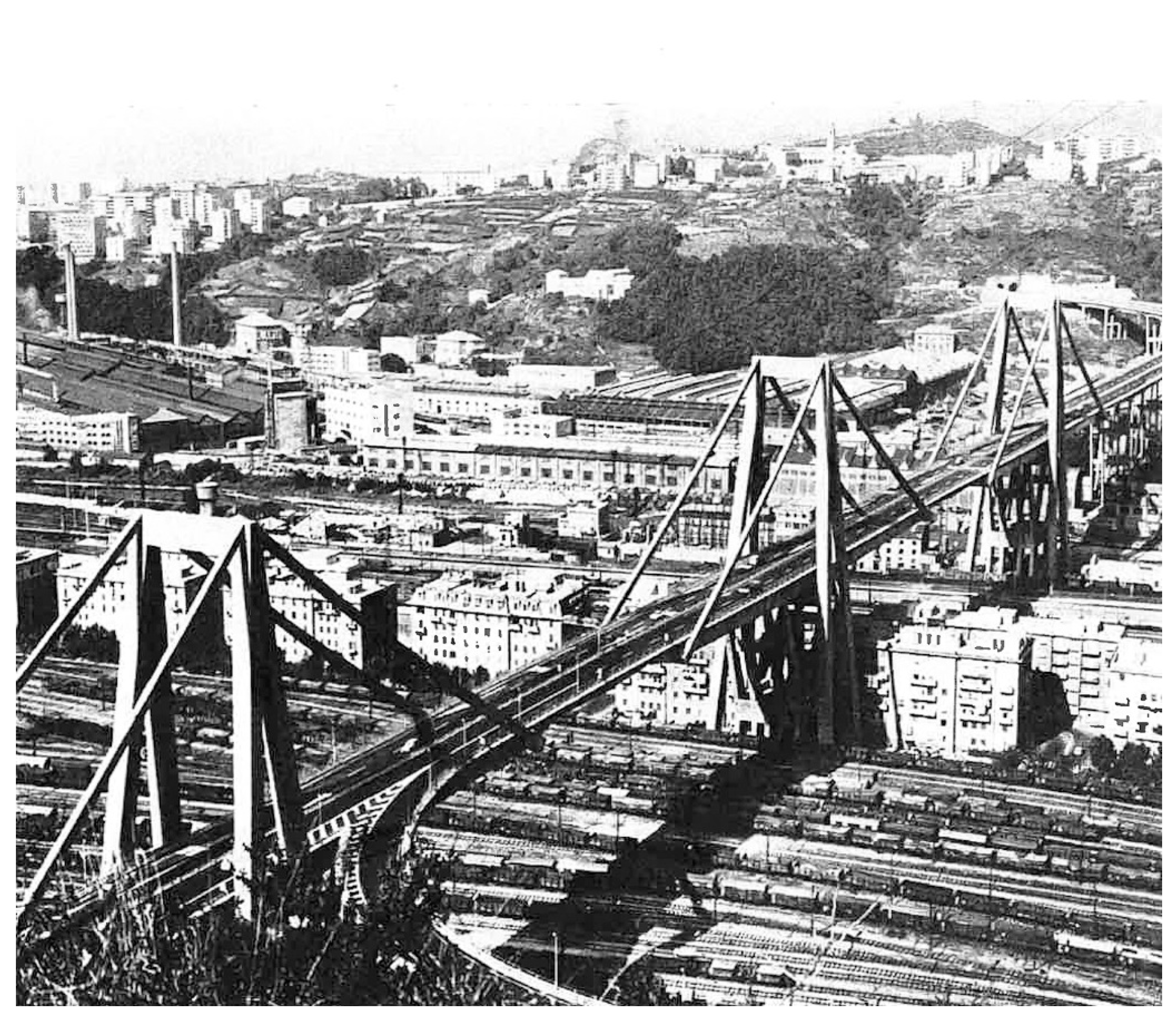
The bridge in Genoa consisted of a three-span viaduct and a multi-span overpass, which connected to the viaduct from the west. The viaduct was constructed over ~80 m wide Polcevera river, from which it derived its official name. The bridge structure was built over the railway line linking Genoa with Milan, the industrial plants, and residential buildings. The viaduct carried the A10 motorway from Genoa to Savona, transferring traffic of a large number of heavy trucks. The carriageway had four lanes, two in both directions. The view of the Polcevera Viaduct from the north-east is shown in Figure 1.
1.2. Static Scheme of the Bridge Structure
The bridge consisted of 11 spans with the following length: 43.00 + 5 × 73.20 + 75.313 + 142.655 + 207.884 + 202.50 + 65.10 = 1102.452 m. The structural scheme of the viaduct and the multi-span overpass are shown in Figure 2.
The static scheme of structures of the viaduct and the multi-span overpass consisted of a multi-span frame with V-type supports (Figure 3a) and spandrel beams with cantilevers on which the suspended spans were supported (the piers of the previously designed bridge in Venezuela are of the X-type [3]). Overpass spans were supported at the cantilevers of the V-type piers Nos. 3 to 8. Whereas the structure of the three other piers of the viaduct (Nos. 9, 10 and 11) was another type. A pylon supporting two pairs of cables was added to each of the framed support. The pylons of the viaduct are shown in Figure 3b. The three reinforced concrete pylons of the portal shape were 90 m high above the terrain. The cross-section of the bridge span was a three cell pre-stressed concrete box. The spandrel beam in the longest span, between the forked columns of support No. 10, had a length of approximately 45 m, and the length of the cantilever was ~65 m. The 18 m wide bridge deck was positioned at an elevation of ~45 m above the terrain.
1.3. Diagonal Stay Cable Structure According to
On both sides of each pylon, two cantilevers of prestressed concrete and steel box were fixed to the pylons. These cantilevers were supporting the suspended span. The steel cables with prestressed concrete shells poured on had a rectangular cross-section and a form of a composite steel and concrete element, a single at the top of the pylon and divided into two equal parts at the deck level. Cross-sections of the diagonal stay cable are shown in Figure 4a (on the left-at the deck level; on the right-at the top of the pylon) [1].
There were 24 steel tendons in the central part of the cross-section of the diagonal stay cable, each consisting of 12 strands with a diameter of 1/2-inch, i.e., 12.7 mm (12T13) with a tensile strength of R = 170 kg/mm2 (ca. 1700 MPa). Those tendons were strained before encasement in concrete and they transferred the weight of the cantilever. The tendons were concreting in segments. Forces in the tendons were transferred to concrete through friction and adhesion forces. Additionally, there were 28 steel tendons located close to the edge of the concrete cross-section, each consisting of four strands with a diameter of 1/2 inch (4T13). Those tendons were located in ducts, strained after hardening of the concrete, and injected afterward. Consequently, the diagonal stay cable is the composite steel and concrete element transferring permanent loads of the suspended span, as well as loads from the road traffic.
Thus, one diagonal stay cable consisted of 52 steel tendons, hereinafter referred to as the “internal tendons”, located inside the diagonal stay-cable made of 400 (24 × 12 + 28 × 4) 1/2-inch tendons. The cross-sectional areas of the steel internal tendons “S”, concrete “C” and the stay-cable “B” are listed in Table 1. There were steel stirrups with a diameter of 6 mm, spaced every 15 cm in the cable. Schematic anchoring of the cable in the deck and at the top of the pylon is shown in Figure 4b.
This type of structural detail of the steel cables with prestressed concrete shells poured on had to ensure the bonding of the steel internal tendons with concrete to the transfer of loads, and also the concrete was to form the corrosion protection of the tendons. Therefore, the load due to road traffic was to be transferred by the entire steel and concrete composite section.
1.4. Construction of the Main Structural Elements of the Bridge in Genoa According to
Overpass spans of about 32 m were supported at the short cantilevers (about 8 m in length), of the V-type piers Nos. 3 to 8. Figure 5a shows the moment of placing the span on the cantilevers of piers Nos. 6 and 7 of the overpass [1].
Structurally independent pylons were constructed at the V-type piers Nos. 9, 10 and 11. Pylon No. 9 was executed first. Figure 5b shows the construction of the pylon and the two-sided cantilevers. These cantilevers were constructed using the cantilever concreting method, with the use of additional compression with external pre-stressing temporary steel tendons laid on the upper surface of the cantilevers (Figure 5c). After pylon No. 9 was completed, two other pylons were built. Each pylon with cantilevers was built independently. Stay cables were made after the pylon and cantilevers were completed. Figure 5d shows completed pylon No. 11—with the cantilevers and prestressed concrete element, support No. 10—with the pylon made and cantilevers but still without cables and support No. 9—with the pylon made but still without cantilevers.
After the completion of the pylon and the cantilevers, the cantilevers were suspended from the pylon using steel tendons (those which would be located in the central part of the concreted cable). After these steel tendons were tensioned, the external temporary tendons used for the construction of the cantilevers were dismantled. Figure 5e shows support No. 10 with concreted cables and support No. 11 with steel tendons before concreting (in this support the external temporary tendons of the cantilevers were still used). The V-type pier with two-sided cantilevers suspended to the pylon and concreted cables formed integrated support for the viaduct. The spans of about 36 m were supported on the cantilevers. Figure 5f shows the moment of placing the span on the cantilevers of piers Nos. 10 and 11.
2. Methods and Materials of Strengthening of the Polcevera Viaduct
2.1. Technical Condition of the Polcevera Viaduct after 25 Years of Service
Several years after the bridge opening to the regular service (in 1967), damage to concrete in the structure was discovered. In the 1980s, extensive renovation works were carried out on the structure. The study of Italstrade in 1988 [4] presents the scope of the renovation work carried out until February 1988. The work concerned primarily the repair of concrete in pylon of the support No. 11 (located in the lower-left corner in Figure 1). It was the first of the pylons built, and it was expected to see more damage than in the other pylons that were constructed later.
The renovation works included removal of loose parts of concrete, cleaning of the surface using water lance, anchoring the steel mesh (with a thickness of 4 mm and mesh size of 10 × 10 cm), on selected concrete surfaces, application of cement mortar with a thickness of ~2 cm and protection of the surface with two anti-corrosion coatings: an epoxy coating and a polyurethane coating. Scaffolding was constructed at the support to carry out the repair works. Figure 6a presents the scaffolding of support No. 11 for repair works planned only at its lower part (state as of the mid-1980s [4]).
Due to the observed poor technical condition of the concrete in the lower part of the pier, it was decided to build scaffolding at the entire height of the pylon (Figure 6b) allowing also the assessment of the technical condition of the upper part of the support, which was difficult to access until then. Apart from damage to the concrete, steel corrosion was found in structural elements of the viaduct, in particular in the upper part of the diagonal stay cable.
In January and March of 1992, two reports [5,6] were drafted by Prof. Manfred Wicke from the Technical University of Innsbruck, Austria. The first report assessed whether the repair works carried out on the structure were sufficient and discussed corrosion of the strands in the diagonal stay cable, while the other report evaluated whether the design for a strengthening of the diagonal stay cable was correct.
The following is the information contained in the first report by Prof. Wicke of January 1992. According to this report, some of the strands in the diagonal stay cable were broken, and some others were heavily corroded. “The worst damage was to be seen at the upper end of the north-western stay-cable from support 11 and was examined by the expert at the time of the visit on 14 January 1992. He was informed then that about 30 to 40 strands were broken or had become slack and that a similar number were badly corroded. This damage is regarded as being of a serious nature”. The strands were visible in a completely deteriorated connection between the cable and the pylon. At the top of the pylon, water was penetrating through the cracked and missing concrete to tendons causing corrosion. “The above assessment applies primarily to the northern stay-cables of support Nos. 9 and 11. In the opinion of the expert, the replacement of the remaining stay-cables will prove to be (…) necessary”. The poor technical condition of the cables resulted in a decrease in the yield strength of the steel in the internal tendons, and further penetration of the water into the cables would result in the breaking of successive strands.
Prof. Wicke assessed that the damaged internal tendons should be replaced by new ones. “This rigorous requirement is called for mainly because the stay-cables have to bear the load of a whole section of the bridge and the consequences of failure would be catastrophic (…). The condition of the steel reinforcement will not permit any postponement as a speedy implementation is required”.
Since the actual technical condition of the tendons was unknown, at least the following provisional measures concerning road traffic were recommended:
- Prohibition of overtaking by trucks and non-standard vehicles.
- Limitation of the traffic speed to 50 km/h.
“A limit on the permitted weight for individual lorries is not required. Exceptional loads should, however, no longer be permitted. With respect to the uncertainties of the actual damage situation and the fact that a failure of the stay-cable might occur without warning, at least the reduction of traffic as supposed above should be imposed. The temporary measures are put forward in the context of the speedy implementations of the repair work”.
In the suspended 36 m long span, that contained 10 tendons, and each tendon consisted of 18 wires with a diameter of 7 mm, some of the wires were broken and some were corroded. “The damage is comparable with that of the stay-cables, but it was reckoned to be less serious on account of the degree of degradation being manifestly smaller, plus the different position of the damaged area in relation to load flow”.
2.2. Strengthening of the Concreted Cables at Support No. 11 of the Polcevera Viaduct between 1992 and 1994
The design of strengthening of the cables was elaborated by Francesco Pisani, the engineer from the Studio Pisani in Rome (formerly associated with Prof. Morandi, responsible for the static calculation of the structure). The design of strengthening was described in the work by Camomilla [7], which is co-authored by the designer.
The assumptions that were taken in designing of strengthening of the diagonal stay cables were as follows:
- Preserving the architecture of the structure.
- High risk is associated with the demolition of the diagonal stay cables, e.g., with the lack of possibility to maintain the stiffness of the concrete support.
- No possibility of closing traffic through the bridge.
- Ensuring such compressive stress in concrete after strengthening that the steel-concrete cross-section transferred loads as a composite cross-section.
According to the design by Pisani, the diagonal stay cable should be strengthened by 12 long external tendons. Each tendon was designed to consist of 22 strands with a diameter of 15 mm (22T15). The tendons were located along two vertical surfaces of the diagonal stay cable, six on each side (Figure 7). The area of the steel cross-section of long external tendons (“T”) is given in Table 1. The tendons were laid in steel brackets on the diagonal stay cable in the spacing of 4.0 m. The tendons were anchored to the steel elements, the so-called cap at the top of the pylon, and to the transverse beam at the deck, which is also connected to the short external tendons. There were six of those short tendons, and each consisted of 31 strands with a diameter of 15 mm (31T15). They were located at the bridge deck level, along the two horizontal surfaces of the cable at the length of about 6.5 m. The short tendons were needed due to the adopted method of strengthening the diagonal stay cable.
The method of strengthening was as follows:
- The concrete was removed in the lower part of the cable at the length of 6.5 m.
- Short tendons were installed and concreted at the length of ~6.0 m with high-strength concrete (leaving the non-concreted 0.5 m gap).
- Short tendons were strained to the maximum value and all old, corroded strands of internal tendons (pre-tensioned and post-tensioned) in the non-concreted 0.5 m gap were cut off.
- The stresses in short tendons were successively reduced while increasing the stress in the long external tendons to the design value.
The strengthening of the diagonal stay cables at support No. 11 was implemented between 1992 and 1994. First, cables located at the northern side (from the mountains) were strengthened, and later the southern side (from the seaside). In addition, the method of fastening of the cables was changed at the top of pylon No. 10 by providing a steel cap. This type of element on pylon No. 11 is shown in Figure 8d. Pylon No. 9 was not repaired or rebuilt.
2.3. Characteristics of the Diagonal Stay Cable before and after Strengthening
Although the report by Prof. Wicke from March 1992 [6] mostly concerned the design of strengthening of the diagonal stay cables at support No. 11, it also contained information on the stay cable before strengthening. According to that report, the stay cable at the top of the pylon was tensioned with the force of 19.1 MN (26.1–7.0) under permanent load, whereas concrete was compressed with the force of 7 MN and the internal tendons tensioned with the force of 26.1 MN.
As the result of the strengthening, long external tendons were strained with the force of 13.5 MN. That force resulted in the increase of the compressive force in concrete by 10.2 MN and reduction of the tensile force in the corroded internal tendons by 2.1 MN (the remaining force of 1.2 MN was transferred to the cantilever beam, causing torsion and bending moments). Thus, after strengthening and under permanent load, the concrete in the diagonal stay cable was compressed with the force of 17.2 MN (7.0 + 10.2) and the corroded internal tendons were tensioned with the force of 24.0 MN (26.1–2.1). While, under live load, the diagonal stay cable strengthened with external tendons was tensioned with the force of 6.0 MN, whereas the tendons were tensioned with the force of 5.1 MN and external tendons with the force of 0.9 MN.
3. Results of Strengthening According to the Author
3.1. Characteristics of the Diagonal Stay Cable According to the Author
In 1993, the author of the paper was a participant of the 31st IRI (Istituto per la Ricostruzione Industriale) course organized in Italy for bridge experts from different countries. During several months of the course, he had the opportunity to familiarize himself with the work of design and construction companies in Italy. In April 1993, he stayed at the Italstrade company in Milan. Since the company was involved in the reconstruction of the Polcevera Viaduct, the author was sent to Genoa as part of the visit to the company. During this period, the diagonal stay cables of the viaduct were strengthened according to the design by Pisani.
Table 1 summarized data characterizing the structure of the diagonal stay cable before and after strengthening with the use of the long external tendons. These are cross-sectional area and tensile stiffness.
The cables were not strengthened at two supports of the viaduct, Nos. 9 and 10. The structure of the stay cable at those supports was constructed according to the design by Prof. Morandi.
Assuming that:
- internal forces specified in the report of Prof. Wicke (Wicke, March 1992) are correct,
- the longitudinal modulus of elasticity of the tendon E = 180,000 MPa,
- the modulus of elasticity of concrete E = 32,000 MPa,
- the length of the cable is 92.2 m (based on Figure 3b),
- the cross-sectional area and the tensile stiffness are calculated and specified in Table 1, it can be calculated that in the non-strengthened cable:
- ➢
- Under permanent load:
- the tensile stress in internal tendons was 515.1 MPa (26.1:0.05067),
- the compressive stress in concrete was 6.1 MPa (7:1.14493),
- the elongation of the cable transferring the load as a steel-concrete section was 38.5 mm (19.1 × 92,200:45,758.4),
- the elongation of the cable transferring the load only through internal tendons would be 193.1 mm (19.1 × 92,200:9120.6);
- ➢
- Under live load equal to 6.0 MN:
- the tensile stress in internal tendons was 23.6 MPa (6.0:0.05067 × (9120.6:45,758.4)),
- the compressive stress in concrete was 4.2 MPa (6.04:1.14493 × (36,637.8:45,758)),
- the elongation of the cable transferring the load as a steel-concrete section was 12.1 mm (6.0 × 92,200:45,758.4),
- the elongation of the cable transferring the load only through internal tendons would be 60.7 mm (6.0 × 92,200:9120.60).
In summary, in the non-strengthened cable under total load (permanent and live load):
- the tensile stress in internal tendons was 538.7 MPa (515.1 + 23.6),
- the compressive stress in concrete was 10.3 MPa (6.1 + 4.2),
- the elongation of the cable transferring the load as a steel-concrete section, was 50.6 mm (38.5 + 12.1),
- the elongation of the cable transferring the load only through internal tendons would be 253.8 mm (193.1 + 60.7),
- the increase in elongation of the cable transferring loads only through internal tendons would be 203.2 mm (253.8–50.6); such an increase in elongation of the cable would cause vertical displacement equal to 108.9 mm (sin32.4o × 203.2; the value of the angle was assumed based on Figure 3b).
The non-strengthened diagonal stay cable can be characterized as follows. Under the total action of loads, the stresses in the internal tendons were 539 MPa (which is ca. 32% of the tensile strength of steel (539:1700 × 100)) and 10.3 MPa in the concrete (which represents ca. 30% of compressive strength of concrete). The elongation of the cable transferring the load as a composite steel-concrete section was 50.6 mm. Assuming that the concrete is not compressed, and the load is transferred only through the internal tendons, the elongation of the cable would be 253.8 mm. An increase in elongation of the cable transferring the load only through internal tendons would result in vertical displacement of the end of the cantilever equal to 108.9 mm. According to Prof. Wicke (Wicke, March 1992), “vertical displacement of more than 100 mm will seriously damage the main bridge girder at the central pier”.
In summary, the cracking of concrete in the diagonal stay cable confirmed the lack of composite action of the concrete in the load distribution causing an increase in elongation of the steel cable resulting in such a vertical displacement (ca. 110 mm) that the failure could be caused due to breaking of the cable.
In the case of one of the pylons-No. 11-4 cables were strengthened (whereas the new tendons cannot be strained to the required degree due to a limited pressure on deteriorated concrete). Assuming that the internal tendons can further transfer the load, the strengthened cable may be characterized as follows:
- ➢
- Under permanent load:
- the tensile stress in internal tendons was 473.7 MPa (24.0:0.05067),
- the compressive stress in concrete was 15.0 MPa (17.2:1.14493);
- ➢
- Under live load equal to 6.0 MN:
- the compressive stress in concrete was 4.2 MPa [6.0:(11,449.3 + 506.7 × (180,000:32,000))],
- the tensile stress in external tendons amounted to 19.3 MPa (0.9:0.04665).
After strengthening of the cable with the long external tendons, only a 9% decrease in the tensile force was achieved under permanent load in the corroded tendons ((24–26.1):24 × 100) and as much as 2.5 times increase in the compressive force in the concrete (17.2:7).
Under live load, the stress in external tendons was 19.3 MPa, which is ca. 1.1% (19.3:1700 × 100) of the breaking strength of steel (assuming that steel with non-inferior properties was used compared to the designed properties of the viaduct).
The stresses in concrete were considerably increased as a result of strengthening of the stay cable. Moreover, a slight decrease of stresses in the corroded internal tendons was achieved with a technically questionable assumption that both the internal tendons stressed before and after concreting will still transfer loads. Thus, after strengthening the stay cable, the corroded internal tendons will be subjected to dynamic load by road traffic. The requirement stated in the first report by Prof. Wicke (Wicke, January 1992), i.e., “to release the old strands, cannot be met”.
The author’s observations about the strengthening of the structure of the viaduct by compressing the diagonal stay cables:
- External tendons slightly relieve strains from the corroded internal tendons—as much as 85% (5.1:6.0 × 100) of the load will still be transferred by the corroded stay cable under live load and only 15% (0.9:6.0 × 100) by external tendons. Figure 8a shows pylon No. 11 with strengthened north-eastern cable. Figure 8b presents strengthening of the cable with long external tendons in the view from the viaduct deck and Figure 8c-in the view from the top of pylon No. 11. Figure 8d shows the newly installed steel cap on pylon No. 11;
- The level of prestressing the long external tendons is limited by the technical condition of the concrete in the diagonal stay cable-stresses at the level of 1% of the tensile strength of steel will be generated in external tendons. Figure 8e shows the cable of pylon No. 11 before strengthening;
- Compression of the curved structural element, like the diagonal stay cable, is difficult in practice (Figure 8c,e).
Summarizing, a different method of strengthening, than in the case of pylon No. 11, is recommended for the other two pylons (Nos. 9 and 10). Strengthening of pylon No. 10 was possible because scaffolding was already built beside that pylon (Figure 8f).
3.2. Author’s Concept of Strengthening of Pylons Nos. 9 and 10 of the Viaduct from 1993
Figure 9 shows three viaduct supports. Each of them was treated differently:
- the cables were strengthened at support No. 11,
- a steel cap was installed at support No. 10 to connect the cables at both sides of the pylon (with scaffolding),
- no works were performed at support No. 9.
According to the author, the compression of the cable with external tendons at support No. 11 will be ineffective. Strengthening the curvilinear, corrosion-damaged cable could not be effective-sectional stressing was difficult for technological reasons, and the stress level of the external tendons was low due to the poor technical condition of the concrete. However, the lack of any strengthening of the cables at supports Nos. 9 and 10 was a technical and organizational mistake.
After all, the technically correct solution to reduce the load on the concreted cable would be to add independent steel cables attached to the pylon, e.g., located in parallel to the existing diagonal stay cable. With such a solution, the concreted cable would be considerably unloaded. Additional suspension cables in the structure allow for better load distribution and redundancy-if one element is damaged, other elements will take a greater load and the object will not suddenly crash.
The method of strengthening the structure of the facility could be as follows:
- removing the suspended span-unload the support, including brackets,
- repair and reinforce of concrete supports, including brackets and concrete tendons,
- adaptation of the pylon and brackets to attach additional steel tendons suspending the brackets,
- fixing additional steel tendons to the pylon and brackets,
- strengthening the suspended span (or replacing it with a lighter one) and placing it on the reinforced joints at the ends of the supports.
Such a solution would extend the life of the structure and reduce the risk of a sudden failure. This solution is much simpler than compression of the concreted cable and it could be used on the other two supports—Nos. 9 and 10.
The author submitted his concept of strengthening the viaduct to Italian engineers, who were compressing the concreted cables at support No. 11. Figure 10a shows support No. 10 before strengthening, and in Figure 10b after strengthening. The concept of structural strengthening proposed by the author has not been accepted for various reasons. Certainly one of them-perhaps even the most important one-was the need to change the architecture of the structure. Additional steel cables would change the appearance of the viaduct designed by Prof. Morandi, and this was incompatible with the basic assumption to the design goal of preserving the original appearance of the viaduct.
At the end of the IRI course, a meeting was held with a representative of the Italian government. At the meeting, it was necessary to say in Italian what technical project in Italy had made the most impression on the participant of the course. The author stated that he was most impressed by the structure of Prof. Morandi’s Viaduct in Genoa, which should be properly strengthened as soon as possible because the current way of strengthening will be ineffective. The author presented his concept of strengthening (shown in Figure 10b) as one of the possible applications for strengthening the other two viaduct supports.
The author stated that if the viaduct was not properly strengthened, it may collapse. The conversation took place 25 years before the collapse of the viaduct.
4. Discussion about the Causes of the Viaduct Collapse
4.1. The Consequences of the Viaduct Collapse
The collapse of the Polcevera Viaduct in Genoa, Italy took place on the 14 August 2018 during a violent downpour, as a result of which 43 people were killed and 12 were severely injured. At the time of the viaduct collapse, there were three trucks and 10 cars on the structure (acc. to RAI Television). The section of the viaduct with a length of about 250 m collapsed, i.e., the first pylon on the side of the multi-span overpass (support No. 9 on Figure 1-in the upper right corner and Figure 2), together with frame support, cantilevers, and the suspended spans. In October 2017, the Wadi Kuf Bridge in Libya was closed. After the collapse of the viaduct in Genoa, the bridge in Venezuela over Lake Maracaibo was also closed for the time of repairs. The initial investigation of the causes of the Morandi Viaduct collapse in Genoa as a contribution to the design of pre-stressed structures was presented by the Author in previous publication [8].
4.2. Causes of the Viaduct Collapse According to the Author
4.2.1. General Remarks
The cause of the viaduct collapse was the rupture of one of the stay cables at support No. 9 (Figure 2) holding the cantilever from the side of the multi-span overpass. Presumably, it was the north-western cable. It is one of those northern cables (at the side of the mountains), whose poor technical condition was discussed in the first report of Prof. Wicke [6], and which was not strengthened. According to the author, there were three main causes of the viaduct collapse: material, structural and organizational.
4.2.2. Material Cause
The diagonal stay cable, as the composite steel-concrete structural component, is not a good solution for transferring the tensile force because of its insufficient redundancy. The initial value of the compressive force in steel tendons decreases over time as a result of the so-called pre-stressing losses. The decrease in the value of the compressive force to the value of the initial force may be estimated at up to 20%.
Pre-stressing losses are caused by:
- shrinkage of concrete (decrease in the volume of concrete as a result of drying),
- creep of concrete (increase in deformation without a change in load),
- relaxation of steel (decrease of the pre-stressing force at constant deformation).
The greater pre-stressing losses are, the greater is the length of the compressed element. In this case, the element was very long—it had a length of more than 90 m. Moreover, the shape of the diagonal stay cable changed from straight to more curved and as a result of perpendicular force reduced the value of the stress force. The more curved the shape of the tendon, the greater the value of the perpendicular force and the greater the pre-stressing loss. Hence, the additional compression of the misaligned cable as part of strengthening caused large pre-stressing losses (the more curved the tendon, the greater the losses).
The reduction of the pre-stressing force overtime and the deformation of the diagonal stay cable resulted in cracking of the concrete cover. The cracked cover was not a suitable anti-corrosion protection for the tendons, which under these conditions were subject to accelerated corrosion. Intensive local corrosion occurred in places where oxygen and atmospheric moisture were penetrating through concrete defects. Similar opinion was presented in the article by Biliszczuk [9] “weak point of this structure (…) was corrosion protection for the tendons, particularly in area of crown plate at the pylon top”.
4.2.3. Structural Cause
First of all, the principal rule of designing the cable-stayed structures is to use several or a dozen stay cables supporting the bridge deck to achieve redundancy, and therefore, the damage of one of the cables will not lead (in any case should not lead) to the sudden collapse. The design solution adopted by Prof. Morandi that only two structural components supported the cantilever with the suspended span, excludes any cooperation of these structural components in a situation where one of them is destroyed or damaged (for example, a collapse would also take place even if a vehicle hit the cable and destroyed it). In addition, the replacement of a diagonal stay cable—an important element of the cable-stayed structure—was technically complicated and impossible to perform without closing the traffic on the structure.
Secondly, the cantilever length of approximately 65 m is too large. In the case of a traffic jam on a motorway viaduct, there may be three five-axle trucks with a weight of 40 t and a length of up to 16.5 m in the spacing of about 5 m, on a single lane. This would result in overloading a single cable with vehicles of a total weight of 120 tons, standing on one lane.
Thirdly, the concrete cross-section of the pylon is too small for the cross-section of the diagonal stay cables attached to the pylon. The cables transfer tensile forces and the pylon compressive forces; therefore, buckling should be considered during its design. Consequently, the relationship between the stiffness of the pylon and the cables is imbalance.
Fourthly, the assessment of the technical condition of steel tendons inside the concrete element is very difficult in practice, especially the assessment on the peak of the pylon at the height of 45 m above the deck level.
4.2.4. Organizational Cause
The report of Prof. Wicke from January 1992 [6] showed that the poor technical condition is observed in the cables on the northern side of supports Nos. 9 and 11. Therefore, it is incomprehensible why only diagonal stay cables at support No. 11 were strengthened, and no attempt was made to strengthen the diagonal stay cables at support No. 9. Leaving these cables without any treatment was a mistake, regardless of the ineffective strengthening of cables at support No. 11.
4.3. The Destruction Stages of the Viaduct
The viaduct collapse began with the rupture of the diagonal stay cable. The mechanism of changes in the mechanical properties of the stay cable was as follows:
- The value of the pre-stressing force in the strained cables was reduced as a result of pre-stressing losses.
- Due to the large dead weight of the cable, its shape changed from straight to curved and this led to a decrease of the compressive force, causing tension in concrete at the bottom surface of the cable.
- The decreasing value of the compressive force in the cable as a result of pre-stressing losses and changes in the shape of the diagonal stay cable caused cracking of the concrete, starting from the bottom surface of the diagonal stay cable.
- Cracking of concrete resulted in a decrease of the area of the compressed concrete cross-section that transferred the tension forces.
- The cracked concrete ceased to provide adequate anti-corrosion protection of strands in the tendons and allowed for steel corrosion.
- The strands not protected with concrete cover corroded and successively cracked, causing a decrease in the steel–concrete cross-sectional area of cable transferring the tension forces.
- The decrease of the cross-sectional area of the concreted cable under constant forces resulted in increased stresses in the corroded tendons.
- With such a decrease in the value of the pre-stressing force in the cables that concrete was not compressed in no place of the cable’s cross-section, the tension forces were transferred only by the corroded tendons.
- When the load is transferred only by the corroded internal tendons, the elongation of the cable would be greater than 20 cm.
- The successive ruptures of the corroded strands in the steel tendons under constant force would cause an increase of stresses in other unbroken strands and their excessive elongation, until the rupture of the last strand in the tendon.
Figure 11 shows the various stages of the destruction of the viaduct. The mechanism of viaduct destruction was as follows:
- The viaduct superstructure allowed for direct loading of the cantilever with three trucks-at the time of the viaduct collapse, presumably three trucks were on the cantilever.
- The cantilever was structurally connected with the diagonal stay cables, with poor technical condition that could not transfer such a heavy live load.
- The overloaded cantilever resulted in a rupture of one of the two cables, loaded more in the upper part due to the dead load of the cable than in the lower part (the weight of 1 m of the cable was ca. 3 t (1.1956 × 2.5).
- The north-western cable was broken at support No. 9 (Figure 11a).
- The broken cable with a weight of about 280 t (92.2 × 1.1956 × 2.5) fell on the cantilever, which resulted in the destruction of its structure and the rupture of the south-western cable (Figure 11b) located on the other side of the carriageway (the force should be determined taking into account the dynamic impact factor, e.g., equal to 1.5).
- The destruction of the cantilever resulted in a collapse of the suspended span supported on the cantilever (Figure 11c).
- The imbalance in the load of the pylon on both sides caused its destruction, and this led to the collapse of the cables, the cantilever, and the span at the eastern side of the pylon (Figure 11d–f).
The study on post-collapse analysis of Morandi’s Polcevera Viaduct in Genoa Italy was presented by others [11]. Their study employed the existing knowledge in estimating the remaining life of the bridge, including: the existing design information about the bridge; post-collapse investigation report of the ministry of infrastructure and transport [12]; and archival truck traffic and axle load data.
5. Conclusions
In the 1960s and 1970s, Prof. Riccardo Morandi designed three bridges with a similar, atypical structure. They were built in Venezuela, Italy, and Libya. During the viaduct collapse on 14 August 2018, the support No. 9 of the viaduct in Italy collapsed. The other two supports, Nos. 10 and 11, were demolished on 28 June 2019 and the Polcevera Viaduct ceased to exist. However, two more bridge structures of this same design by Morandi still exist. It seems that the author’s concept of adding steel cables attached to the pylon could be carried out to strengthen these structures (Figure 10b). Since both structures have a large pylon cap, a fan system of cable arrangement (not a harp system), proposed by the author in Genoa in 1993, could be used. The Author recommends removing the suspended span and placing a span that would not be suspended but would be pulled in (the hinges would be removed—the static scheme of the platform would not be a Gerberian beam, but a continuous beam). In such a situation, additional steel tendons could be evenly distributed over the entire length of the span.
Regardless of which of the solutions is adopted (repair of a suspended span or the use of a continuous structure), there will still be difficulties related to the poor technical condition of all structural elements (damage to concrete and steel corrosion) and the need to perform construction on both sides simultaneously to prevent the destruction of a pylon with too little stiffness.
Fortunately, failure of the bridge structures do not happen very often; however, there are some bridge failures during the construction phase, e.g., in the pre-stress process Cieśla [13]. The historical bridges still in service are seldom subject to failure. According to the author, this may change in the future, and failures of the bridges would happen more frequently than before. Often, unique bridge structures, with large spans do not meet the requirements of the European Standard [14] (EN 1990, 2004), Table 2.1, concerning a safe use period equal to 100 years. The Polcevera Viaduct is an example of such a structure. Many new bridge structures—non-typical with large span lengths and a large length of river crossing—were constructed primarily in the last 20 years. Architects and engineers compete with one another in the design of architecturally attractive bridge structures with extreme dimensions.
The constantly increasing live loads and weather anomalies (the temper wind and the driving rain) cause accelerated degradation of each structure (the Polcevera Viaduct collapsed during a violent downpour). On the other hand, the effects of the collapse of non-typical structures with large spans and large lengths of crossings are proportional to these dimensions and their originality. The period of safe use of structures with a unique design is, in principle, much shorter than assumed for typical structures. In addition, maintaining a good technical condition of such structures is difficult in practice and very costly. It is also difficult and costly to strengthen or dismantle them. The viaduct collapse in Genoa in Italy should be treated as a warning to all bridge administrations to avoid the construction of unusual and excessively large bridges.
Funding
This research received no external funding.
Institutional Review Board Statement
Not applicable.
Institutional Consent Statement
Not applicable.
Data Availability Statement
The study did not report any data outside of this publication.
Conflicts of Interest
The author declares no conflict of interest. The funders had no role in the design of the study; in the collection, analyses, or interpretation of data; in the writing of the manuscript, or in the decision to publish the results.
References
- Morandi, R. Viaducto sobre el Polcevera, en Genowa—Italia. Inf. Construcción 1968, 21, 57–88. [Google Scholar] [CrossRef] [Green Version]
- Troitsky, M.S. Cable-stayed bridges. In Theory and Design; Crosby Lockwood Staples: London, UK, 1977. [Google Scholar]
- Podolny, W., Jr. Concrete cable-stayed bridges. Bridge Eng. 1978, 2, 121–130. [Google Scholar]
- Italstrade. Autostrada Genova-Savona Viadotto Polcevera: Lavori di risanamento della pila. In Lavori Eseguiti da Italstrade a Tutto il 29 Febbraino 1988; 1988; Available online: http://yadda.icm.edu.pl/yadda/element/bwmeta1.element.baztech-192d98c7-1d6b-4fb9-9a16-263b70ddb798 (accessed on 24 August 2021).
- Wicke, M. Interim report on the corrosion damage to the prestressing steel on the “Viadotto sul Polcevera”. In Report to ISA Italstrade Appalti S.p.A.; Innsbruck: Genoa, Italy, 1992. [Google Scholar]
- Wicke, M. 2nd Report on the Polcevera Viaduct. Report to Autostrada S.p.A.; Innsbruck; Springer: Berlin, Germany, 1992. [Google Scholar]
- Camomilla, G.; Pisani, F.; Martinez y Cabrera, F.; Marioni, A. Repair of the Stay Cables of the Polcevera Viaduct in Genova, Italy; IABSE Reports: Zürich, Switzerland, 1995. [Google Scholar]
- Rymsza, J. Causes of the Morandi viaduct disaster in Genoa as a contribution to the design of pre-stressed structures. Roads Bridges—Drog. i Mosty 2020, 19, 5–25. [Google Scholar] [CrossRef]
- Biliszczuk, J.; Teichgraeber, M. O katastrofie wiaduktu Polcevera w Genui, we W³oszech. Inżynieria i Bud 2018, 74, 578–582. [Google Scholar]
- Kostack, K. Fragments of the Animation “Morandi Bridge Destruction Simulation Genoa 2018|Demolition in 2019”. Available online: www.youtube.com/watch?v=Y6suQ0FIoIQ (accessed on 31 August 2021).
- Morgese, M.; Ansari, F.; Domaneschi, M.; Cimellaro, G.P. Post-collapse analysis of Morandi’s Polcevera viaduct in Genoa Italy. J. Civ. Struct. Health Monit. 2020, 10, 69–85. [Google Scholar] [CrossRef]
- Ministero delle Infrastrutture e dei Trasporti, Commissione Ispettiva Ministeriale. Comune di Genova, Autostrada A10—Crollo del Viadotto Polcevera, Evento Accaduto il 14 Agosto 2018; Governo Italiano: Roma, Italy, 2018. [Google Scholar]
- Cieśla, J.; Biskup, M.; Topczewski, Ł.; Skawiński, M. Cases of Bridge Structural Failure during the Process of Pre-Stressing. Roads and Bridges–Drogi i Mosty 2017, 16, 15–35. [Google Scholar] [CrossRef]
- EN 1990. Eurocode. In Basis of Structural Design, Table 2.1; 2004; p. 20. Available online: https://www.phd.eng.br/wp-content/uploads/2015/12/en.1990.2002.pdf (accessed on 24 August 2021).
Figure 1.
View of Polcevera Viaduct from the north-east (Morandi, 1968).

Figure 2.
Structural scheme of the viaduct and the multi-span overpass (Morandi, 1968; dimensions in m).
Figure 2.
Structural scheme of the viaduct and the multi-span overpass (Morandi, 1968; dimensions in m).

Figure 3.
(a) Overpass support (longitudinal and cross-section) (Morandi, 1968). (b) Viaduct support (longitudinal and cross section) (Morandi, 1968).
Figure 3.
(a) Overpass support (longitudinal and cross-section) (Morandi, 1968). (b) Viaduct support (longitudinal and cross section) (Morandi, 1968).

Figure 4.
(a) Cross-sections of the concreted cable (Morandi, 1968). (b) Schematic anchoring of the cable in the deck and at the top of the pylon (Morandi, 1968).
Figure 4.
(a) Cross-sections of the concreted cable (Morandi, 1968). (b) Schematic anchoring of the cable in the deck and at the top of the pylon (Morandi, 1968).

Figure 5.
(a) Placing the span on the cantilevers of supports Nos. 6 and 7 of the overpass (Morandi, 1968). (b) Construction of pylon and cantilevers of support No. 9 of the viaduct (Morandi, 1968). (c) Pre-stressing temporary tendons laid on top of the cantilevers during the construction of the cantilevers (Morandi, 1968). (d) Viaduct supports at different stages of construction: No. 9—completely executed, No. 10—with the two-sided cantilevers made and No. 11—with the pylon made (Morandi, 1968). (e) Viaduct supports at different stages of construction: No. 10—with concreted cables and No. 11—with steel tendons before concreting (Morandi, 1968). (f) Placing the span on cantilevers of supports Nos. 10 and 11 of the viaduct (Morandi, 1968).


Figure 6.
(a) Support No. 11 with scaffolding in the lower part. (b) Support No. 11 with scaffolding at full height (Italstrade, 1988).
Figure 6.
(a) Support No. 11 with scaffolding in the lower part. (b) Support No. 11 with scaffolding at full height (Italstrade, 1988).

Figure 7.
Strengthening of diagonal stay cable according to the design by F. Pisani.

Figure 8.
(a) Support No. 11 with strengthened north-eastern concreted cable (photo by Rymsza; April 1993). (b) Strengthening of the concreted cable with long external tendons—view from the deck (photo by Rymsza; April 1993). (c) The north-western concreted cable after strengthening—view from the top of pylon No. 11 (photo by Rymsza; April 1993). (d) Steel cap on pylon No. 11 (photo by Rymsza; April 1993). (e) The south-western concreted cable before strengthening—view from the top of pylon No. 11 (photo by Rymsza; April 1993). (f) View from the top of pylon No. 11 to pylon No. 10 with scaffolding (photo by Rymsza; April 1993).


Figure 9.
View of the 3 supports of the viaduct—No. 11 with strengthened concreted cables, No. 10 with an additional steel cap and No. 9 without any structural changes (photo by Rymsza; April 1993).
Figure 9.
View of the 3 supports of the viaduct—No. 11 with strengthened concreted cables, No. 10 with an additional steel cap and No. 9 without any structural changes (photo by Rymsza; April 1993).

Figure 10.
(a) Support No. 10 of the viaduct before strengthening. (b) Strengthening of support No. 10 of the viaduct according to the concept of Rymsza of 1993.
Figure 10.
(a) Support No. 10 of the viaduct before strengthening. (b) Strengthening of support No. 10 of the viaduct according to the concept of Rymsza of 1993.

Figure 11.
Fragments of the animation showing the probable course of the viaduct collapse (author of the animation: Kai Kostack, [10]).
Figure 11.
Fragments of the animation showing the probable course of the viaduct collapse (author of the animation: Kai Kostack, [10]).


Table 1.
Characteristics of the concreted cable before and after strengthening.
| Data | Unit | S | C | B | T |
|---|---|---|---|---|---|
| A | (cm2) | 506.7 | 11,449.3 | 11,956.0 | 466.5 |
| EA | (MN) | 9120.6 | 36,637.8 | 45,758.4 | 8397.0 |
Designations: A—cross-sectional area; EA—tensile stiffness where E stands for longitudinal modulus of elasticity; S—steel internal tendons of the cable; C—concrete in the cable; B—composite steel and concrete cable; T—long external tendons of the cable.
Publisher’s Note: MDPI stays neutral with regard to jurisdictional claims in published maps and institutional affiliations. |
© 2021 by the author. Licensee MDPI, Basel, Switzerland. This article is an open access article distributed under the terms and conditions of the Creative Commons Attribution (CC BY) license (https://creativecommons.org/licenses/by/4.0/).
Share and Cite
MDPI and ACS Style
Rymsza, J. Causes of the Collapse of the Polcevera Viaduct in Genoa, Italy. Appl. Sci. 2021, 11, 8098. https://doi.org/10.3390/app11178098
AMA Style
Rymsza J. Causes of the Collapse of the Polcevera Viaduct in Genoa, Italy. Applied Sciences. 2021; 11(17):8098. https://doi.org/10.3390/app11178098
Chicago/Turabian StyleRymsza, Janusz. 2021. "Causes of the Collapse of the Polcevera Viaduct in Genoa, Italy" Applied Sciences 11, no. 17: 8098. https://doi.org/10.3390/app11178098
Note that from the first issue of 2016, this journal uses article numbers instead of page numbers. See further details here.