
Multi-Objective Aerodynamic Design Optimisation Method of Fuel Cell Centrifugal Impeller Using Modified NSGA-II Algorithm

Abstract
:1. Introduction
- The working environment is different. The FC reactor requires oil-free air, while the centrifugal impeller used in ICE is driven by oil-lubricated bearings, which can cause reactor contamination.
- The rated rotational speed is different. The ICE can make the centrifugal impeller reach more than 200,000 revolutions per minute (rpm) using high-temperature exhaust gas. Meanwhile, the exhaust gas of the FC cannot drive the centrifugal impeller to the required speed. The centrifugal impeller can only be driven by oil-free electric bearings, and its maximum speed can only reach 140,000 rpm. Further, the rated speed of 80,000 rpm–110,000 rpm is considered reasonable.
- It has a different working condition range. The specific speed of the centrifugal impeller in the FC is usually smaller than that of the ICE [5]. Further, their operating conditions are different. The operating range of the FC centrifugal impeller is narrow and usually runs along the surge boundary, while the operating range of the ICE centrifugal impeller is larger. If the ICE centrifugal impeller is applied to the FC system, there is a high risk of surge or blockage. In summary, FC centrifugal impellers need to be specifically designed and optimised for their own use.
2. DNSGA Algorithm
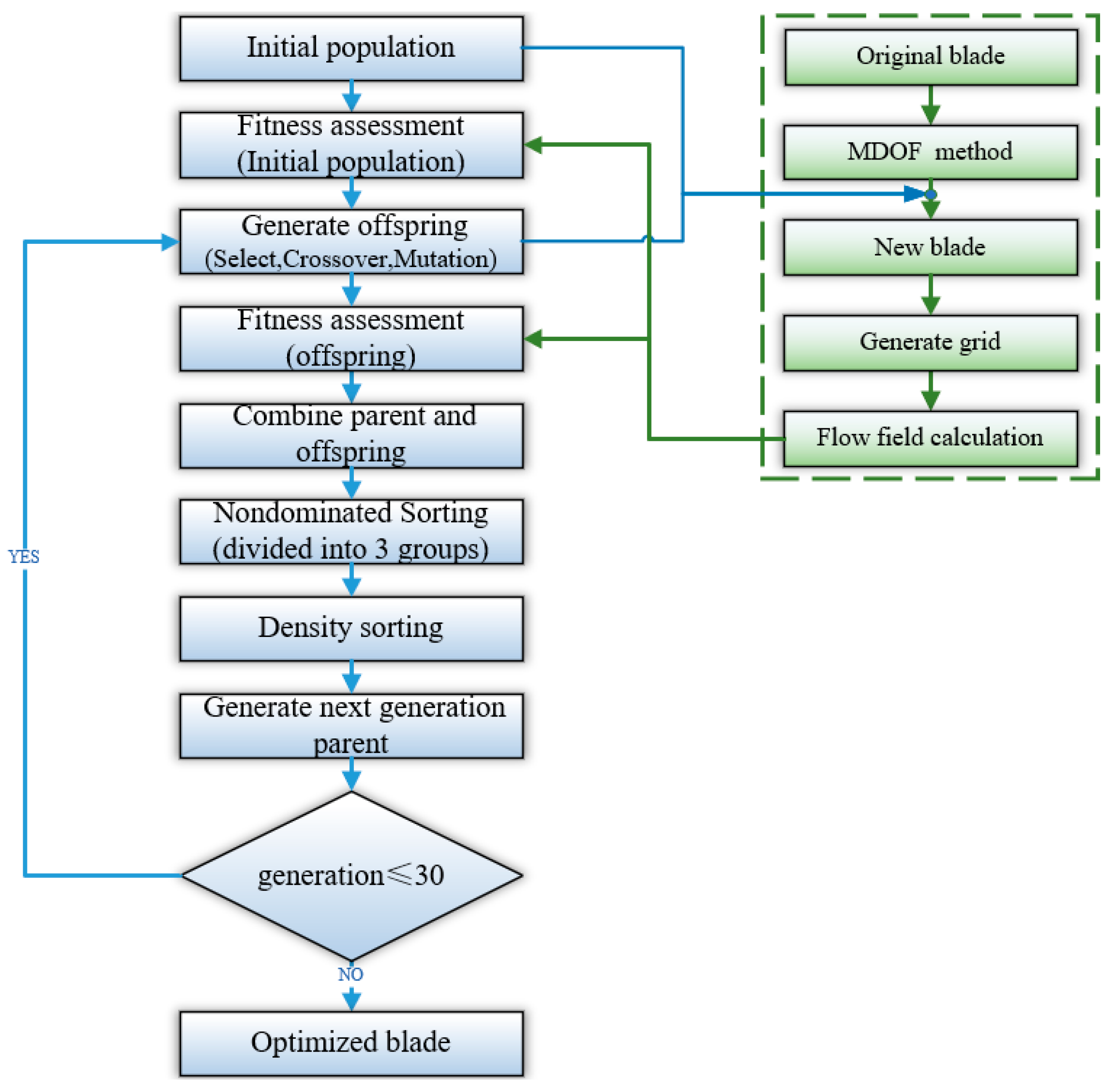
2.1. Algorithm Framework
- (1)
- Randomly generate an initial population P0 to start the evolution;
- (2)
- Perform the binary tournament selection, simulated binary crossover and polynomial variation on P0 to generate new offspring ;
- (3)
- Evaluate the fitness function so that multi-objective values are obtained for each individual;
- (4)
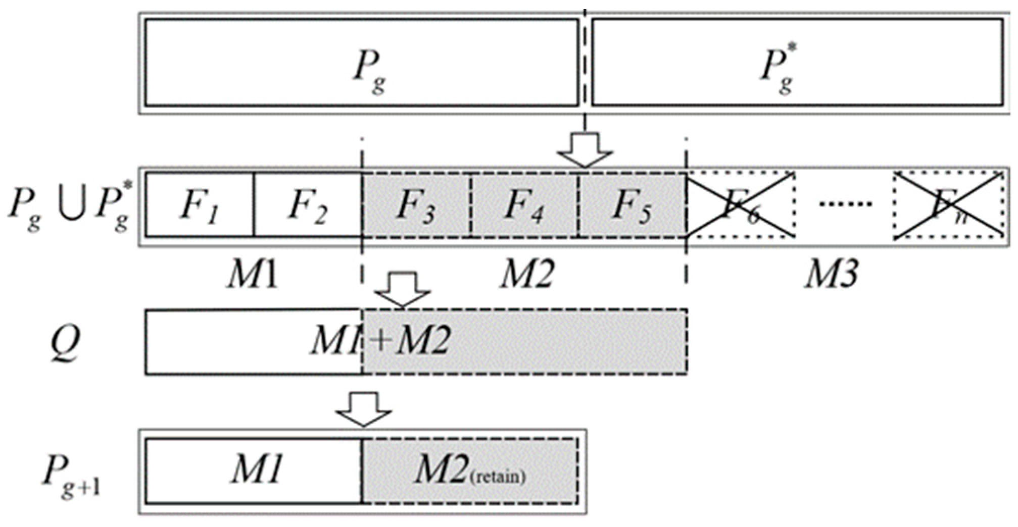
- Sort all individuals in and into F1, F2, F3……Fn based on non-dominance.
- (5)
- Divide F1, F2, F3……Fn into the three groups of M1, M2 and M3;
- (6)
- Generate the next population according to the spatial density operator ordering;
- (7)
- Return to step 2 until the end of the maximum number of iterations.
2.2. Spatial Density Ordering
- (1)
- M1 and M2 are combined into group Q.
- (2)
- The two individuals with the lowest spatial density in Q are found, and at least one belongs to M2.
- (3)
- If one individual belongs to M1 and the other belongs to M2. The individual belonging to M2 is directly removed from Q. If both individuals belong to M2, the one who has a lower spatial density with other individuals in Q is deleted.
- (4)
- Return (2) and (3) in a loop until the total number of individuals in Q reaches the population size.
2.3. Algorithm Validation
3. Multi-Objective Aerodynamic Design Optimisation of Centrifugal Impeller
3.1. Numerical Methods and Validation
3.1.1. Numerical Method
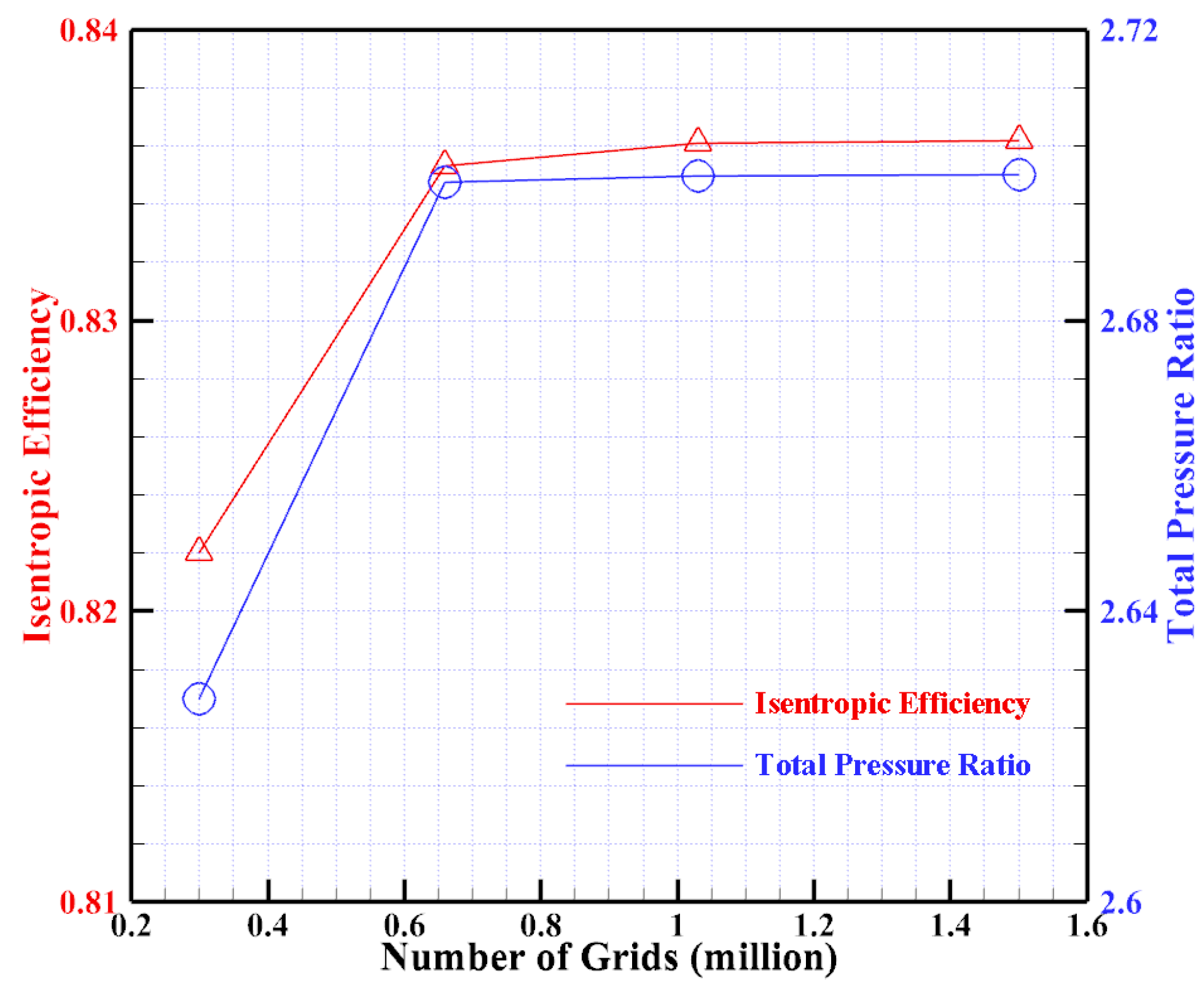
3.1.2. Mesh Generation and Independence Verification
3.1.3. Numerical Method Validation
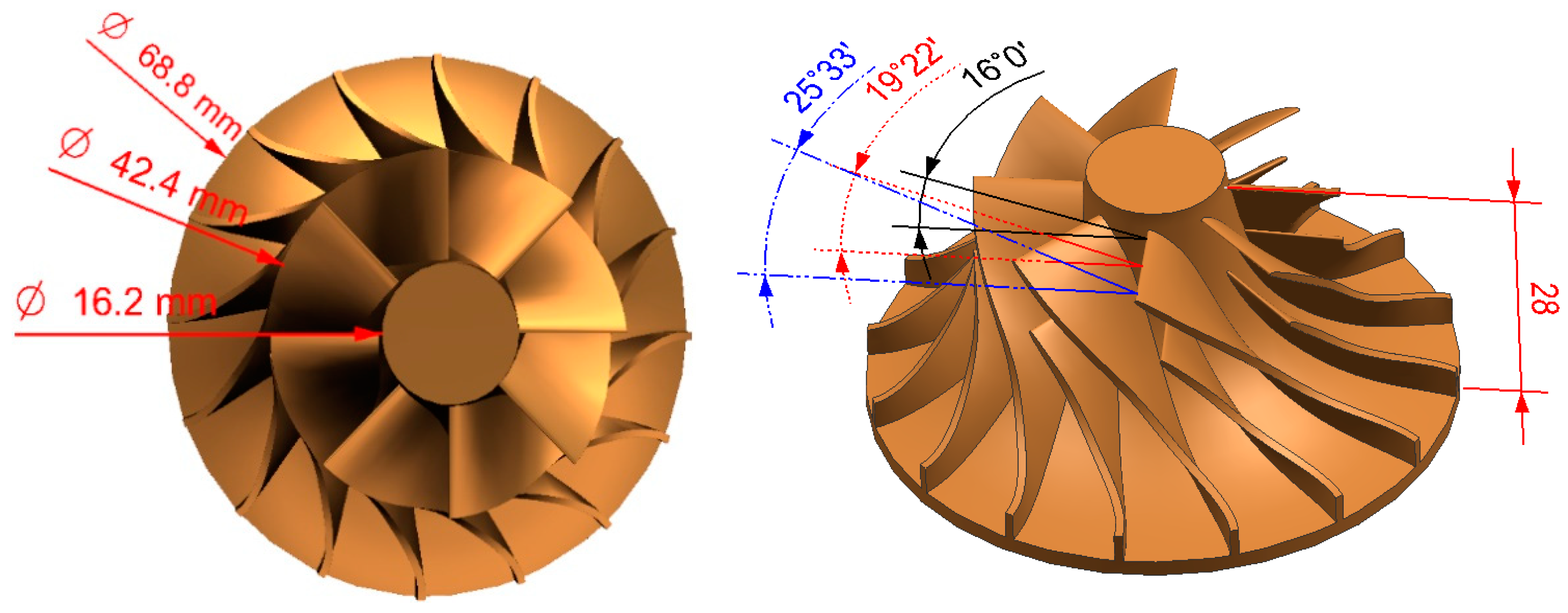
3.2. Optimisation Object
3.3. Optimisation Objectives and Constraints
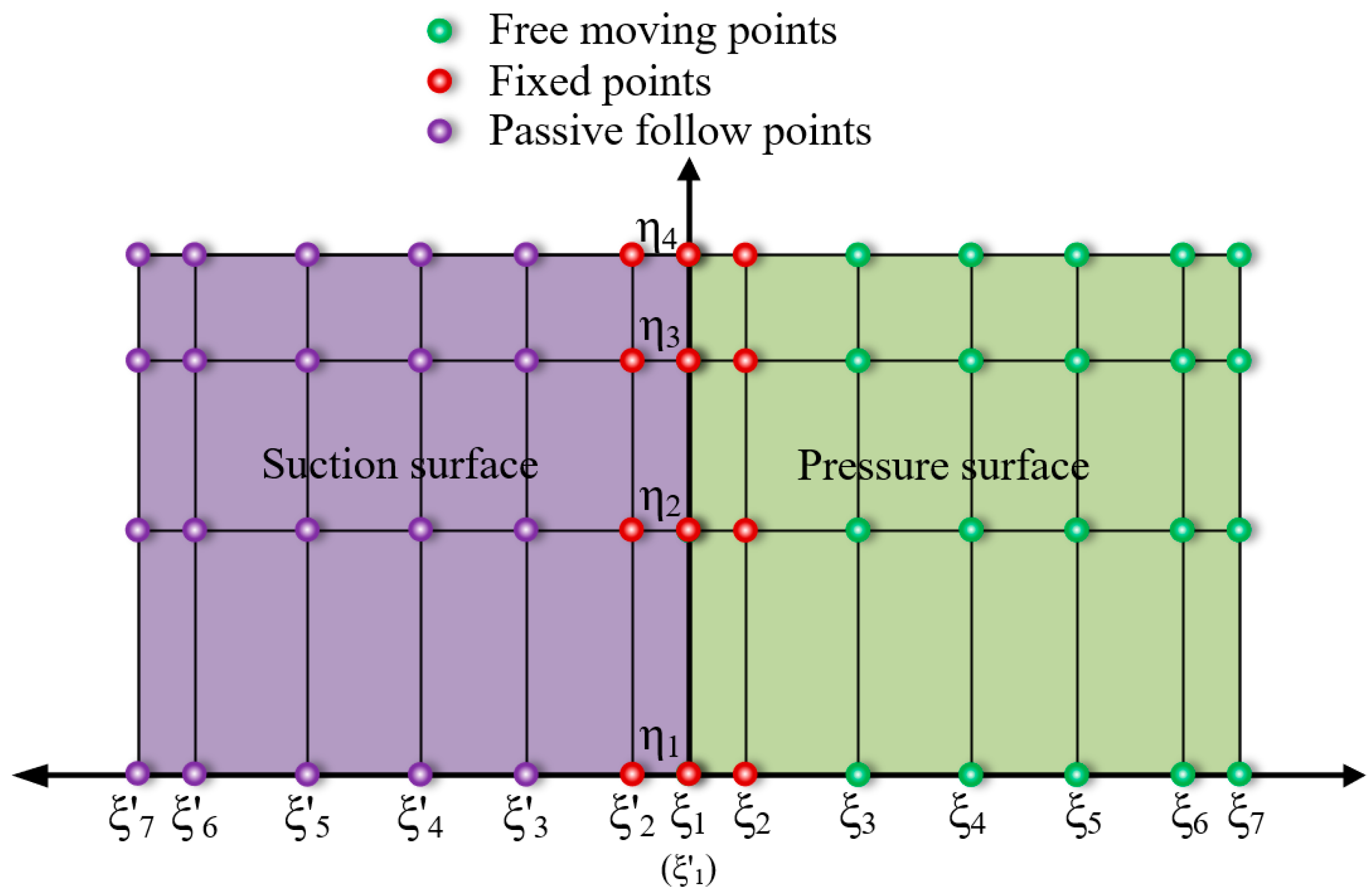
3.4. Parameterisation Method
3.5. Optimisation Process and Algorithm Parameter Setting
3.6. Optimisation Results and Analysis
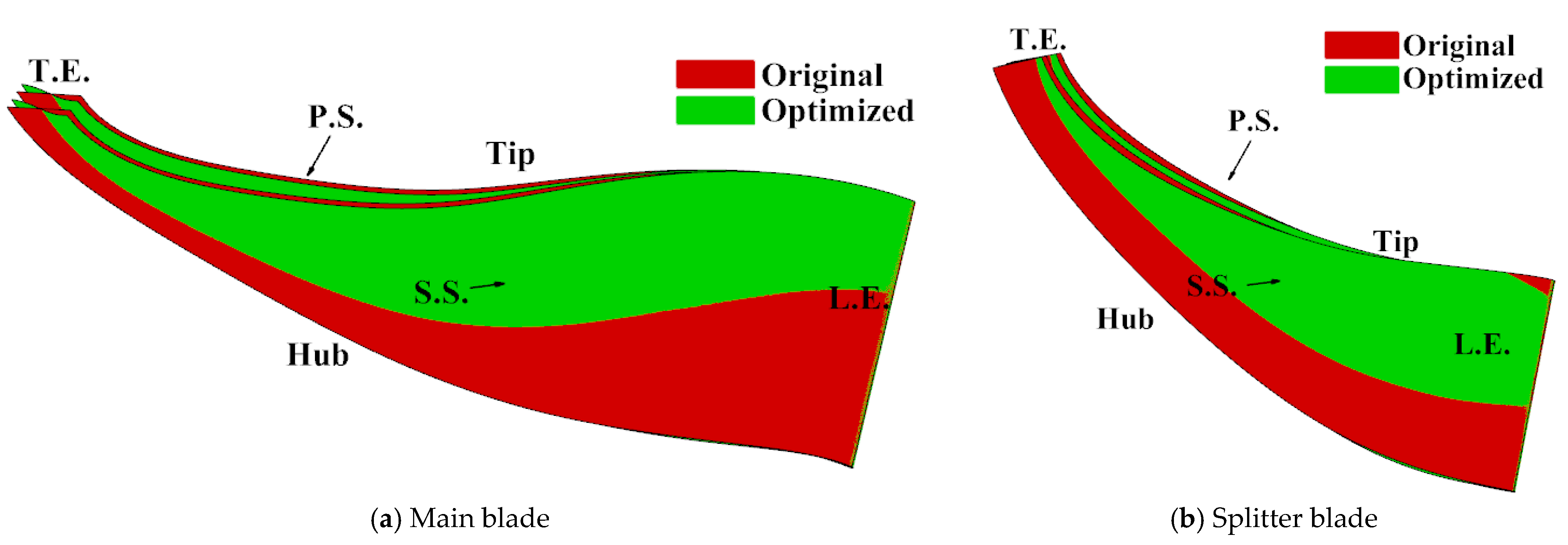
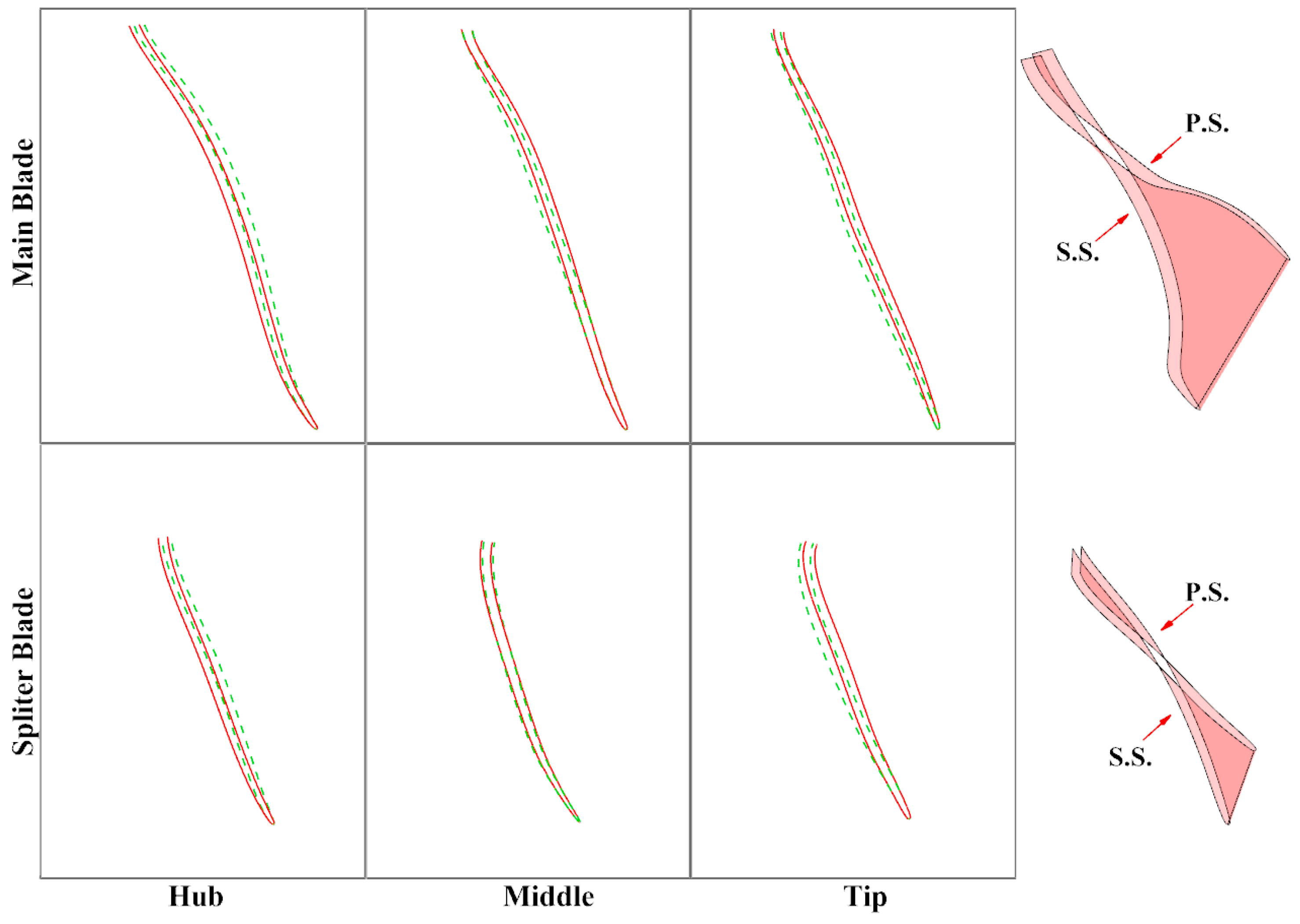
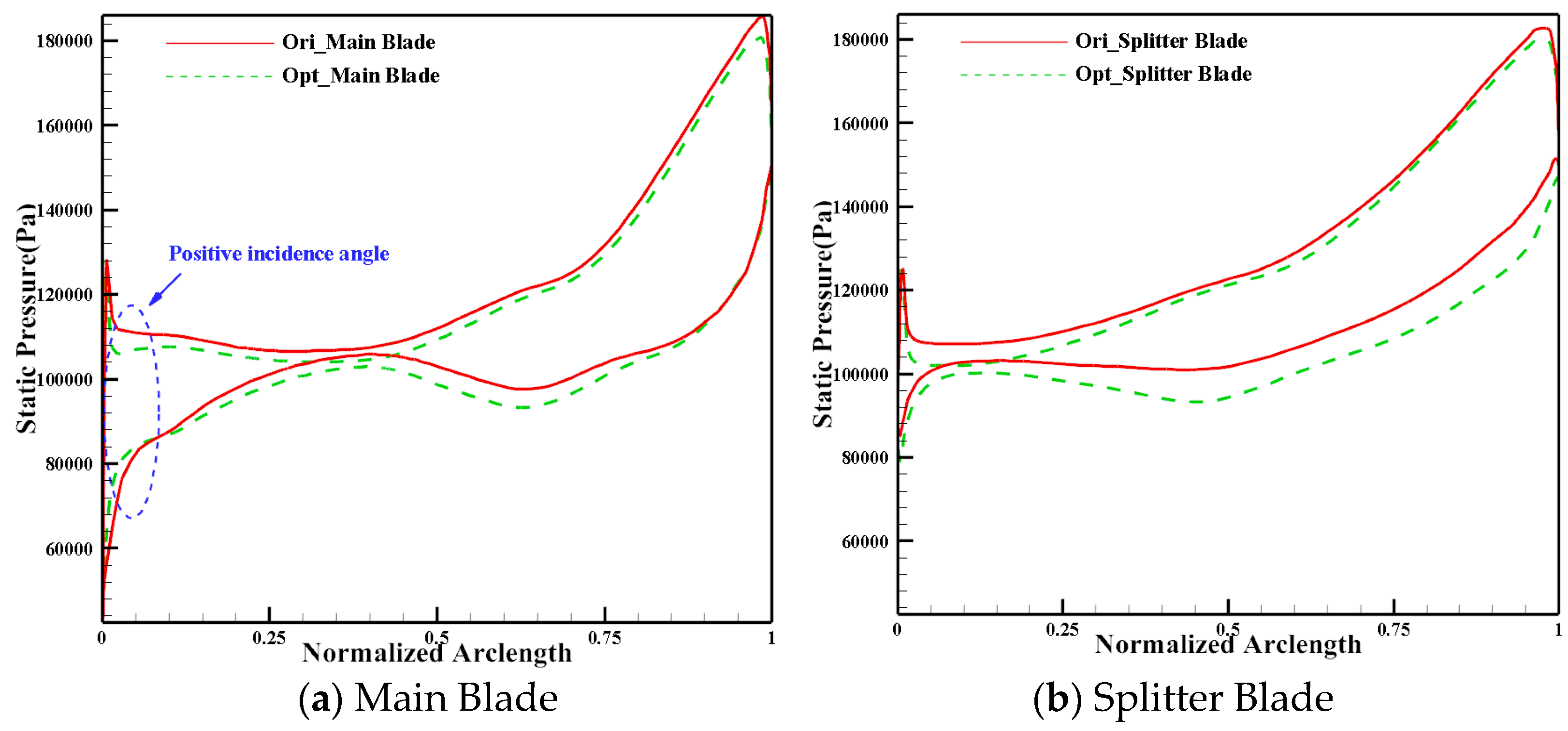
3.6.1. Comparison of Blade Geometry
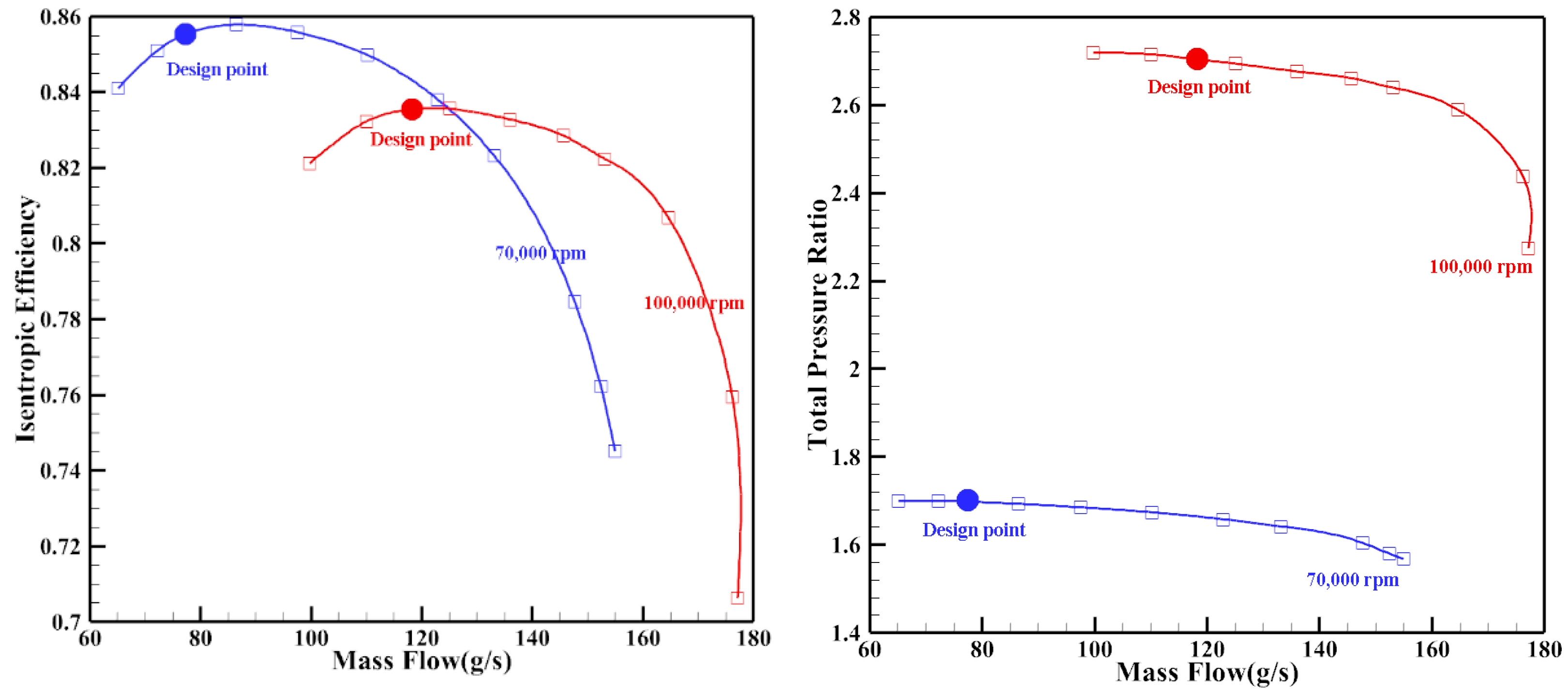
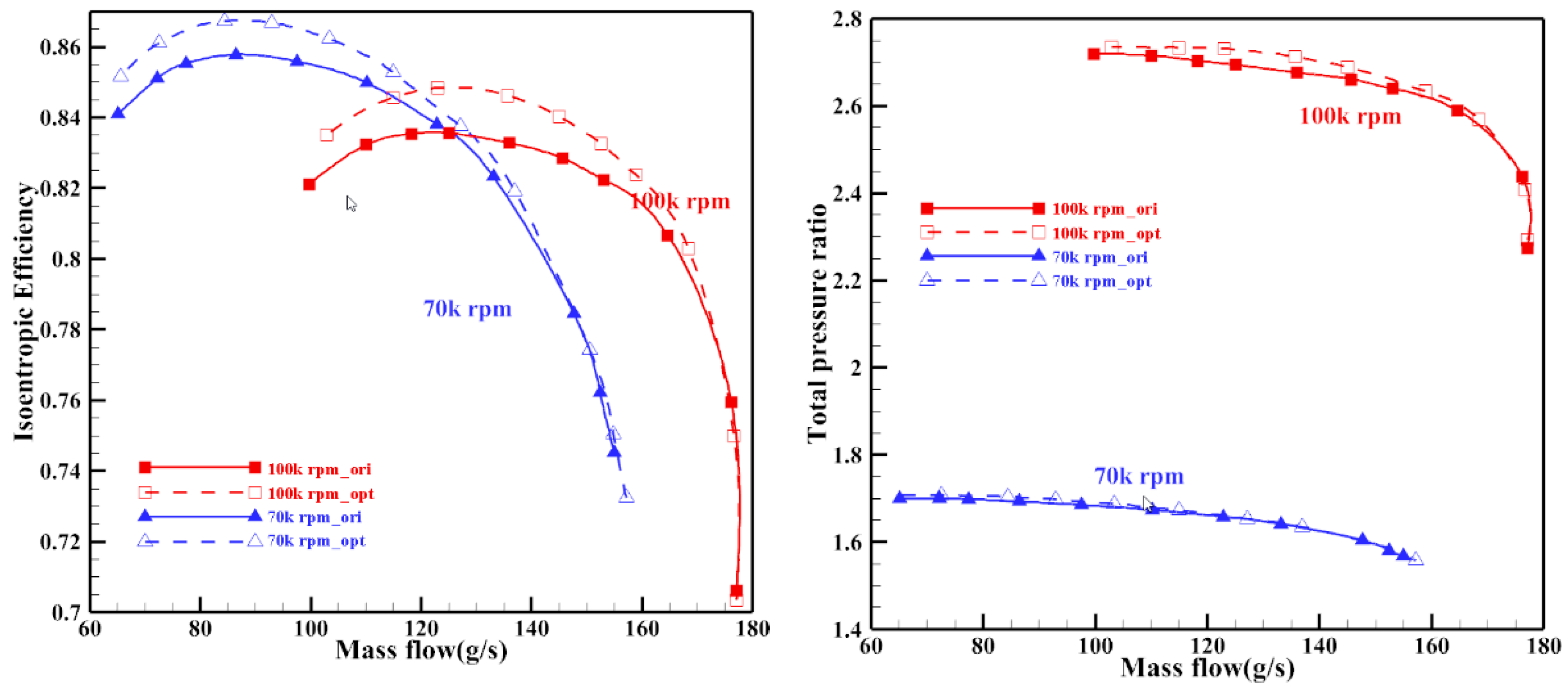
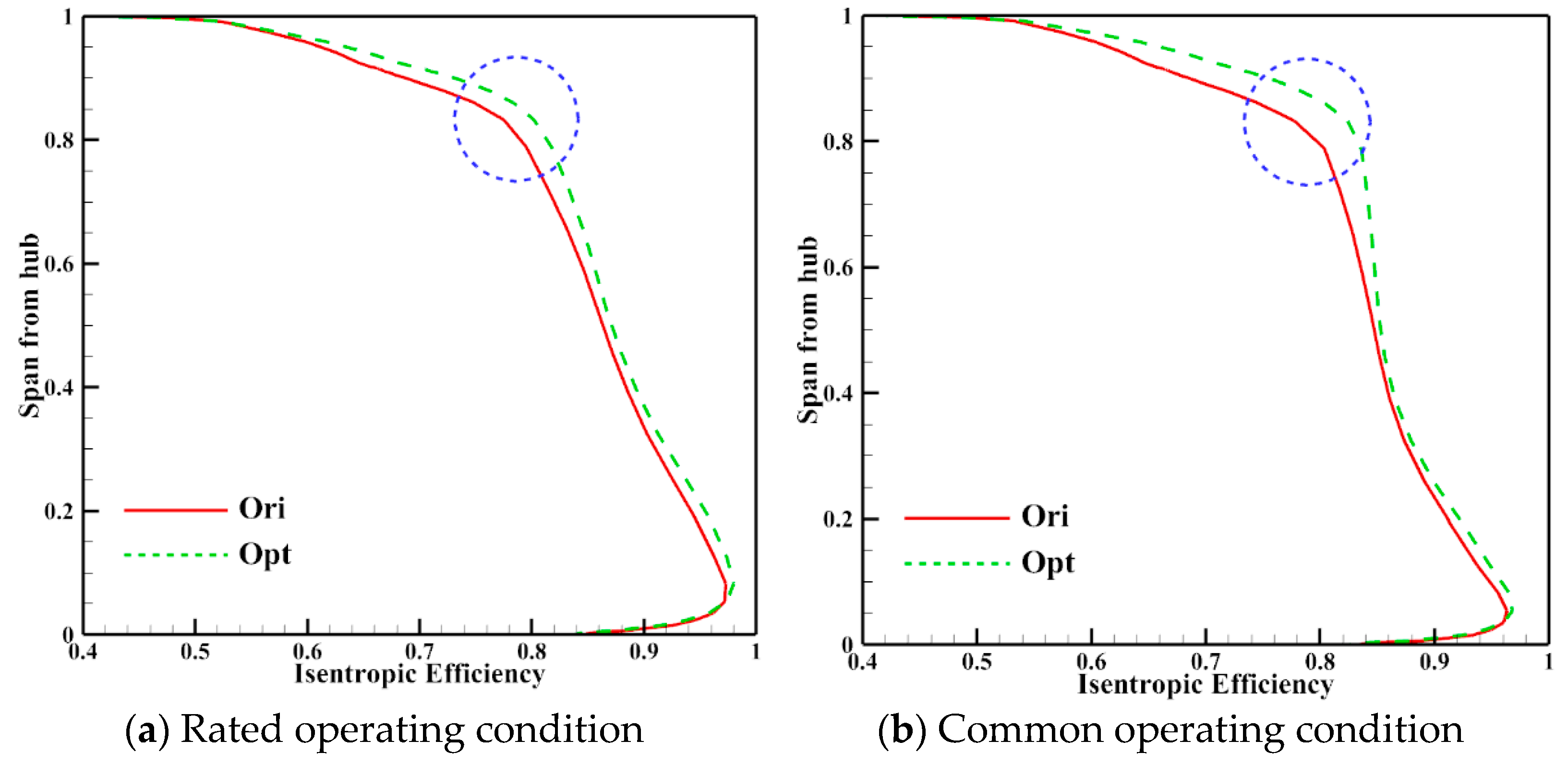
3.6.2. Comparison of Multi-Conditions Aerodynamic Performance before and after Optimisation
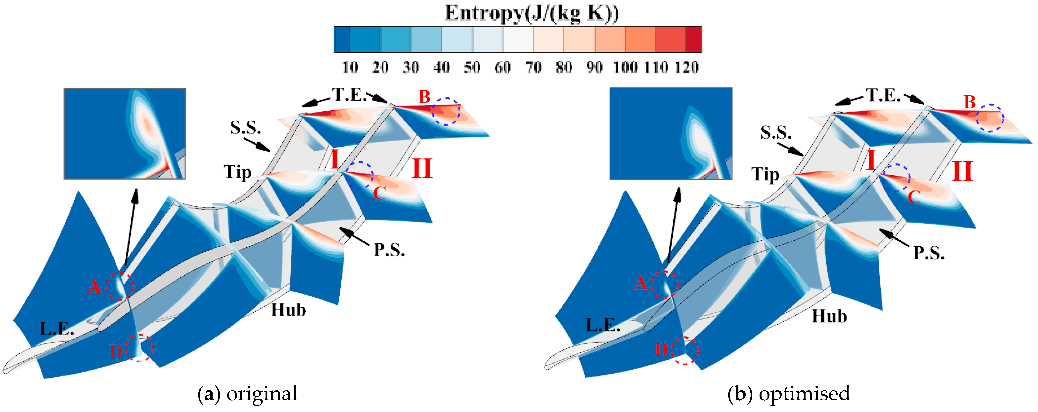
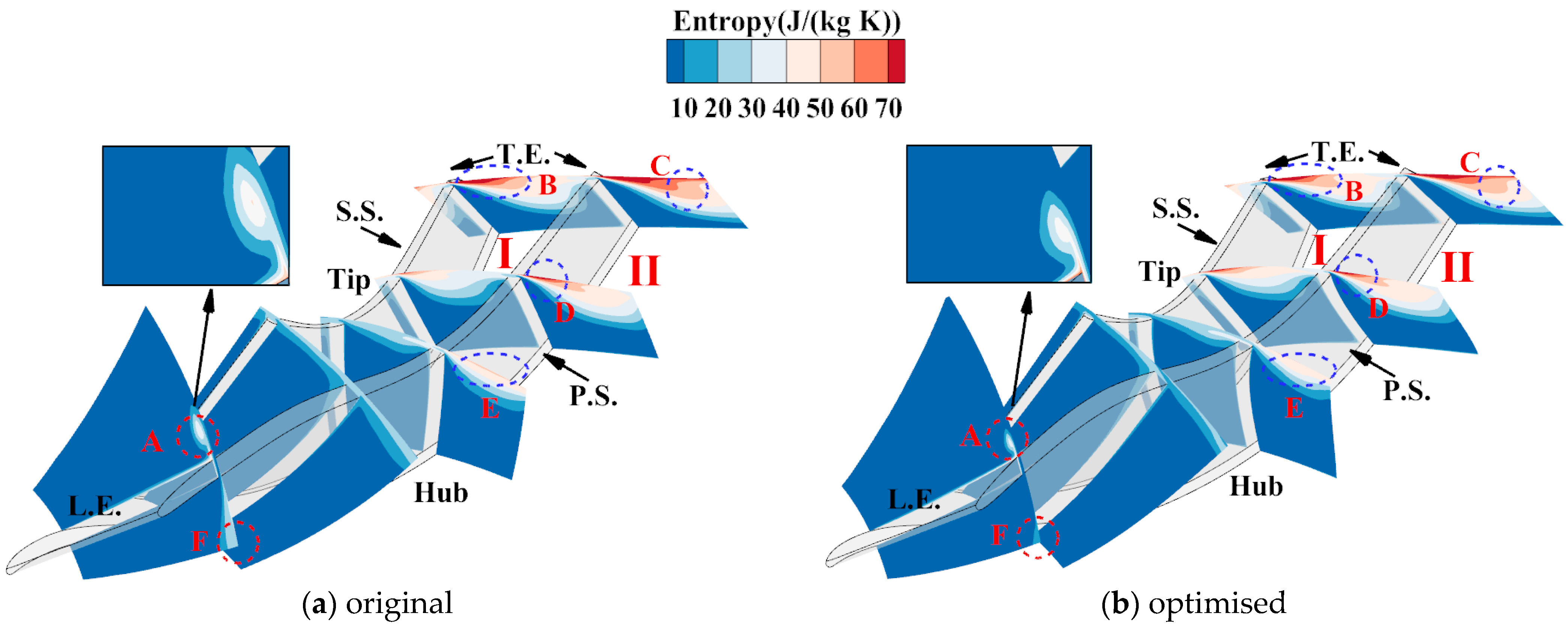
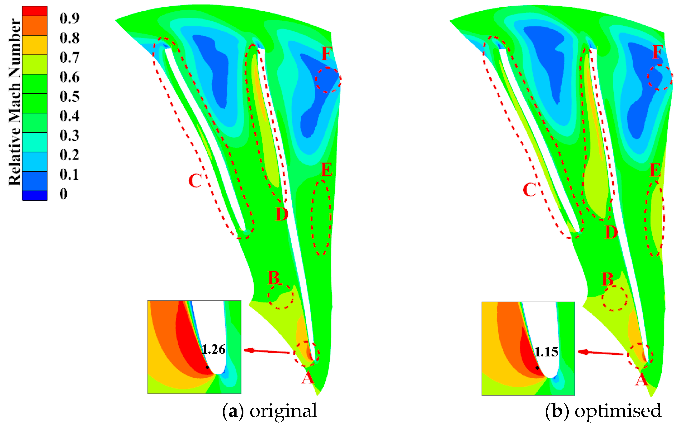
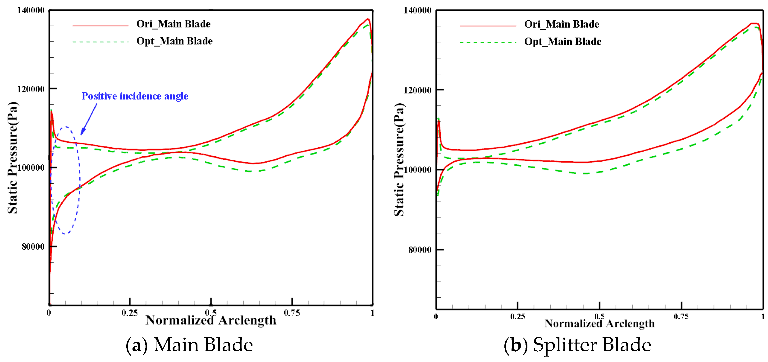
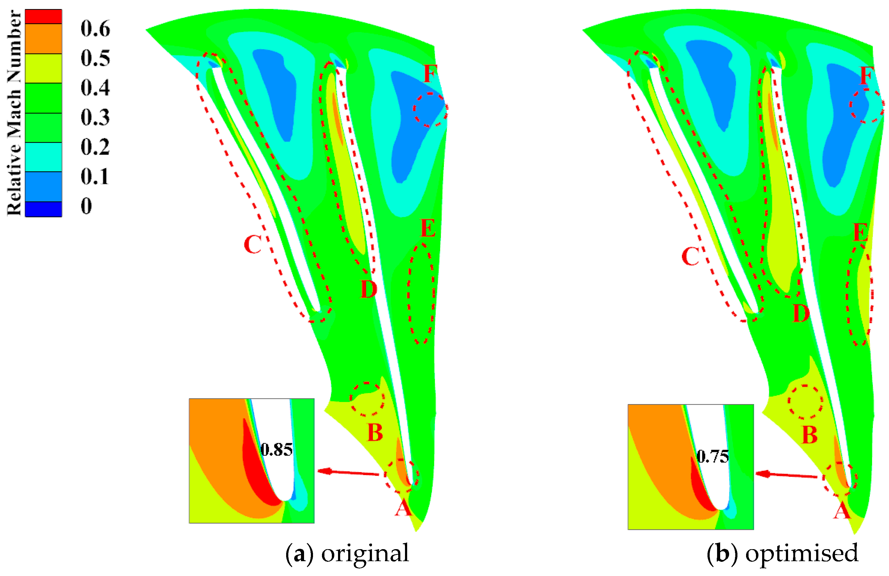
3.6.3. Flow Field Analysis
4. Conclusions
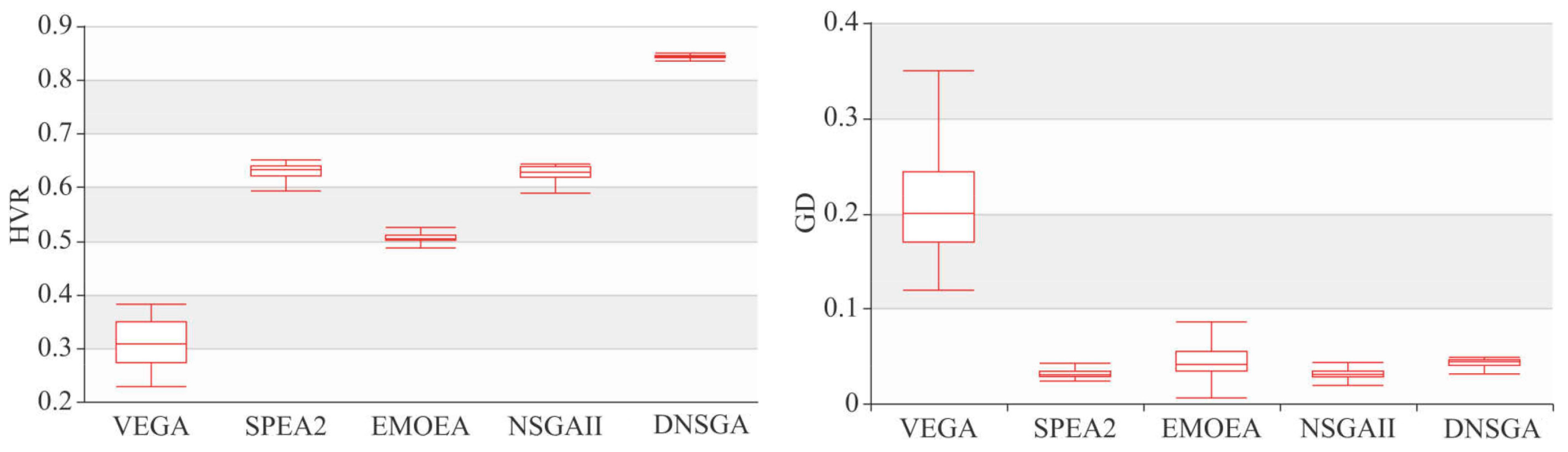
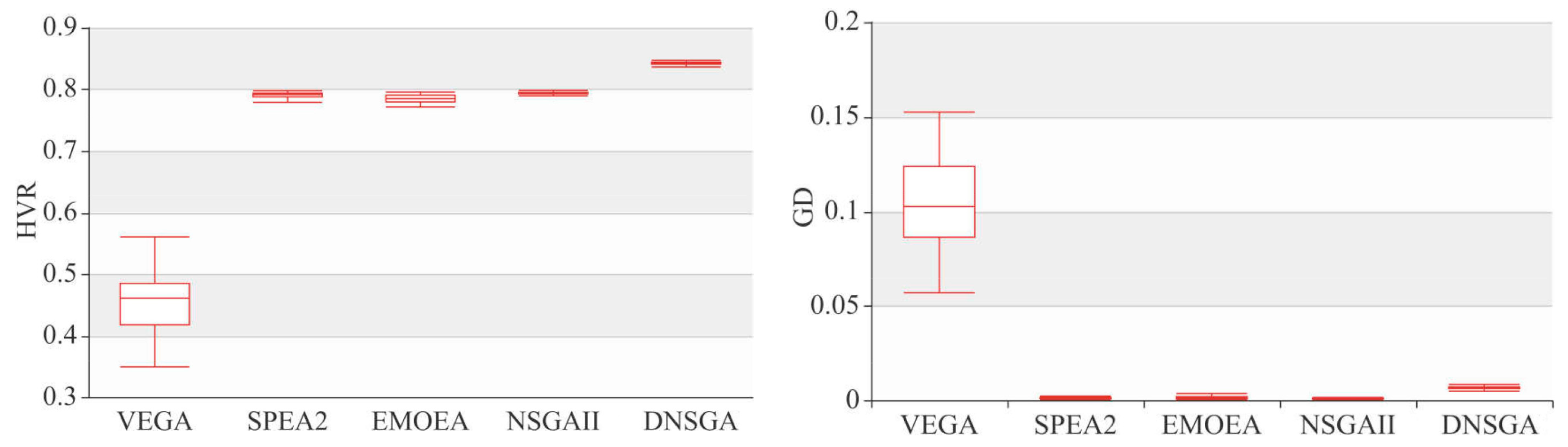
- Compared with other classical multi-objective evolutionary algorithms, DNSGA performs well in population diversity and convergence, especially concerning greater improvement in diversity. This optimisation algorithm improves the traditional method of NSGA-II for selecting the value of the objective function by improving the division of non-dominated ranking and spatial density ranking on decision variables. This provides a new scientific method for the application and research of the multi-objective evolutionary algorithm.
- The optimised geometric deformation of the blade increases the back-bend angle of the blade, the positive angle of attack at the inlet, and the relative Mach number in the blade channel. These changes reduce the diffuser angle and reverse the pressure gradient, reducing the separation loss and improving the flow at the downstream outlet. Under multi-working conditions, the aerodynamic performance curve moved upward as a whole, and the flow condition was significantly improved. The isentropic efficiency under the rated conditions increased by 1.2%, the flow increased by 9.1%, the pressure ratio increased by 0.24%, and the comprehensive margin increased by 10%. The isentropic efficiency under common working conditions increased by 1.29%, the flow increased by 8.8%, the pressure ratio increased by 0.74%, and the comprehensive margin increased by 6.2%. Moreover, it is verified that the aerodynamic optimisation of the FC impeller can improve the efficiency of rated and common working conditions simultaneously. The centrifugal impeller design optimisation system presented in this paper provides technical support and a new method for scientific research to study the aerodynamic optimisation of centrifugal impellers for vehicle-mounted FCs.
- The parametric method used in this paper is based on the Bezier surface blade optimization method. The limitation of this method is that the change of one variable control point on the Bezier surface will cause the change of the entire surface and cannot achieve the local optimization of the blade geometry, so as not to get the best blade geometry. In order to overcome this drawback, we will introduce a more flexible B-spline surface parameterization method or Free-Form deformation method, which can do to control the local surface variation and thus may obtain a blade geometry with better aerodynamic performance.
Author Contributions
Funding
Institutional Review Board Statement
Informed Consent Statement
Data Availability Statement
Conflicts of Interest
Nomenclature
| Abbreviations | |
| SD | spatial density |
| FC | fuel cell |
| FCS | fuel cell system |
| FCVs | fuel cell vehicles |
| CFD | computational fluid dynamics |
| NVH | noise, vibration and harshness |
| 3D | three-dimensional |
| ICE | internal combustion engines |
| MDOF | multi-degree-of-freedom |
| GA | genetic algorithm |
| DNSGA | spatial density NSGA-II |
| PF | Pareto frontier |
| HVR | The hypervolume ratio |
| GD | generational distance |
| Ori | original |
| Opt | optimized |
| L.E. | leading edge |
| T.E. | trailing edge |
| DOE | Department of Energy |
| H | height |
| Symbol | |
| output power of the FC stack | |
| mass flow | |
| average voltage of the cell | |
| stoichiometric ratio of the air | |
| P0 | initial population |
| new offspring | |
| spatial density operator | |
| spatial density operator with weights | |
| weight of the ith dimension variable | |
| rpm | revolutions Per Minute |
| isentropic efficiency at the design point of 70,000 rpm | |
| isentropic efficiency at the design point of 100,000 rpm | |
| mass flow at the original impeller design point at 70,000 rpm | |
| mass flow at the optimised impeller design point at 70,000 rpm | |
| mass flow at the original impeller design point at 100,000 rpm | |
| mass flow at the optimised impeller design point at 100,000 rpm | |
| total pressure ratios at the original impeller design point at 70,000 rpm | |
| total pressure ratios at the optimised impeller design point at 70,000 rpm | |
| total pressure ratios at the original impeller design point at 100,000 rpm | |
| total pressure ratios at the optimised impeller design point at 100,000 rpm | |
| optimisation variable | |
| upper bound of the optimisation variable | |
| lower bound of the optimisation variable | |
| ξ | unitized bezier plane horizontal coordinates |
| η | unitized bezier plane vertical coordinates |
| Ps | Total pressure at the surge point |
| Total pressure at the design point | |
| Mass flow at the surge point | |
| Mass flow at the design point | |
References
- Wang, G.; Yu, Y.; Liu, H.; Gong, C.; Wen, S.; Wang, X.; Tu, Z. Progress on design and development of polymer electrolyte membrane fuel cell systems for vehicle applications: A review. Fuel Process. Technol. 2018, 179, 203–228. [Google Scholar] [CrossRef]
- Ha, K.-K.; Lee, C.H.; Kim, C.M.; Kim, S.H.; Ahn, B.K. A Study on the Characteristics of an Oil-Free Centrifugal Compressor for Fuel Cell Vehicles. SAE Int. J. Altern. Powertrains 2016, 5, 167–174. [Google Scholar] [CrossRef]
- Li, Y.; Pei, P.; Ma, Z.; Ren, P.; Huang, H. Analysis of air compression, progress of compressor and control for optimal energy efficiency in proton exchange membrane fuel cell. Renew. Sustain. Energy Rev. 2020, 133, 110304. [Google Scholar] [CrossRef]
- Wan, Y.; Guan, J.; Xu, S. Improved empirical parameters design method for centrifugal compressor in PEM fuel cell vehicle application. Int. J. Hydrog. Energy 2017, 42, 5590–5605. [Google Scholar] [CrossRef]
- Zhang, Y.; Xu, S.; Wan, Y. Performance improvement of centrifugal compressors for fuel cell vehicles using the aerodynamic optimization and data mining methods. Int. J. Hydrog. Energy 2020, 45, 11276–11286. [Google Scholar] [CrossRef]
- Yu, W.; Sichuan, X.; Ni, H. Air Compressors for Fuel Cell Vehicles: An Systematic Review. SAE Int. J. Altern. Powertrains 2015, 4, 115–122. [Google Scholar] [CrossRef]
- Meroni, A.; Zühlsdorf, B.; Elmegaard, B.; Haglind, F. Design of centrifugal compressors for heat pump systems. Appl. Energy 2018, 232, 139–156. [Google Scholar] [CrossRef]
- Ahluwalia, R.K.; Wang, X.; Kwon, J.; Rousseau, A.; Kalinoski, J.; James, B.; Marcinkoski, J. Performance and cost of automotive fuel cell systems with ultra-low platinum loadings. J. Power Sources 2011, 196, 4619–4630. [Google Scholar] [CrossRef]
- Li, X.; Liu, Z.; Lin, Y. Multipoint and Multiobjective Optimization of a Centrifugal Compressor Impeller Based on Genetic Algorithm. Math. Probl. Eng. 2017, 2017, 1–18. [Google Scholar] [CrossRef] [Green Version]
- Ekradi, K.; Madadi, A. Performance improvement of a transonic centrifugal compressor impeller with splitter blade by three-dimensional optimization. Energy 2020, 201, 117582. [Google Scholar] [CrossRef]
- Li, Z.; Zheng, X. Review of design optimization methods for turbomachinery aerodynamics. Prog. Aerosp. Sci. 2017, 93, 1–23. [Google Scholar] [CrossRef]
- Mirjalili, S.; Gandomi, A.H.; Mirjalili, S.Z.; Saremi, S.; Faris, H.; Mirjalili, S.M. Salp Swarm Algorithm: A bio-inspired optimizer for engineering design problems. Adv. Eng. Softw. 2017, 114, 163–191. [Google Scholar] [CrossRef]
- Cao, Y.; Lodewijks, G.; Li, W. Bi-swarm particle swarm optimizer with novel neighborhood topology strategy and its application of intermodal transportation. In Proceedings of the 2019 IEEE International Conference on Systems, Man and Cybernetics (SMC), Bari, Italy, 6–9 October 2019; pp. 3741–3745. [Google Scholar]
- Shaukat, N.; Ahmad, A.; Mohsin, B.; Khan, R.; Khan, S.U.-D.; Khan, S.U.-D.; Deinert, M. Multiobjective Core Reloading Pattern Optimization of PARR-1 Using Modified Genetic Algorithm Coupled with Monte Carlo Methods. Sci. Technol. Nucl. Install. 2021, 2021, 1–13. [Google Scholar] [CrossRef]
- Deb, K.; Pratap, A.; Agarwal, S.; Meyarivan, T. A fast and elitist multiobjective genetic algorithm: NSGA-II. IEEE Trans. Evol. Comput. 2002, 6, 182–197. [Google Scholar] [CrossRef] [Green Version]
- Duan, B.; Luo, M.; Yuan, C.; Luo, X. Multi-objective hydraulic optimization and analysis in a minipump. Sci. Bull. 2015, 60, 1517–1526. [Google Scholar] [CrossRef] [Green Version]
- Chen, J.; Wu, G. Kriging-assisted design optimization of the impeller geometry for an automotive torque converter. Struct. Multidiscip. Optim. 2017, 57, 2503–2514. [Google Scholar] [CrossRef]
- Wang, X.D.; Hirsch, C.; Kang, S.; Lacor, C. Multi-objective optimization of turbomachinery using improved NSGA-II and approximation model. Comput. Methods Appl. Mech. Eng. 2011, 200, 883–895. [Google Scholar] [CrossRef]
- Huang, R.; Luo, X.; Ji, B.; Wang, P.; Yu, A.; Zhai, Z.; Zhou, J. Multi-objective optimization of a mixed-flow pump impeller using modified NSGA-II algorithm. Sci. China Technol. Sci. 2015, 58, 2122–2130. [Google Scholar] [CrossRef]
- Zitzler, E.; Deb, K.; Thiele, L. Comparison of Multiobjective Evolutionary Algorithms: Empirical Results. Evol. Comput. 2000, 8, 173–195. [Google Scholar] [CrossRef] [PubMed] [Green Version]
- Mojaddam, M.; Hajilouy-Benisi, A.; Abolfazl Moussavi-Torshizi, S.; Movahhedy, M.R.; Durali, M. Experimental and numerical investigations of radial flow compressor component losses. J. Mech. Sci. Technol. 2014, 28, 2189–2196. [Google Scholar] [CrossRef]
- Mojaddam, M.; Hajilouy-Benisi, A. Experimental and numerical flow field investigation through two types of radial flow compressor volutes. Exp. Therm. Fluid Sci. 2016, 78, 137–146. [Google Scholar] [CrossRef]
- Mojaddam, M.; Hajilouy-Benisi, A.; Movahhedy, M.R. Experimental and numerical investigation of radial flow compressor volute shape effects in characteristics and circumferential pressure non-uniformity. Scientia Iranica 2013, 20, 1753–1764. [Google Scholar]
- Xie, H.; Song, M.; Liu, X.; Yang, B.; Gu, C. Research on the Simplified Design of a Centrifugal Compressor Impeller Based on Meridional Plane Modification. Appl. Sci. 2018, 8, 1339. [Google Scholar] [CrossRef] [Green Version]
- Krain, H.; Hoffmann, B.; Pak, H. Aerodynamics of a Centrifugal Compressor Impeller With Transonic Inlet Conditions. In Proceedings of the ASME 1995 International Gas Turbine and Aeroengine Congress and Exposition, Houston, TX, USA, 5–8 June 1995. [Google Scholar]
- Eisenlohr, G.; Krain, H.; Richter, F.-A.; Tiede, V. Investigations of the Flow Through a High Pressure Ratio Centrifugal Impeller. In Proceedings of the ASME Turbo Expo 2002: Power for Land, Sea, and Air, Amsterdam, The Netherlands, 3–6 June 2002; pp. 649–657. [Google Scholar]
- Li, W.; Liu, J.; Fang, P.; Cheng, J. A Novel Surface Parameterization Method for Optimizing Radial Impeller Design in Fuel Cell System. Energies 2021, 14, 2716. [Google Scholar] [CrossRef]
- Burguburu, S.; le Pape, A. Improved aerodynamic design of turbomachinery bladings by numerical optimization. Aerosp. Sci. Technol. 2003, 7, 277–287. [Google Scholar] [CrossRef]
- Cheng, J.; Chen, J.; Xiang, H. A surface parametric control and global optimization method for axial flow compressor blades. Chin. J. Aeronaut. 2019, 32, 1618–1634. [Google Scholar] [CrossRef]
- Huang, S.; Cheng, J.; Yang, C.; Zhou, C.; Zhao, S.; Lu, X. Optimization Design of a 2.5 Stage Highly Loaded Axial Compressor with a Bezier Surface Modeling Method. Appl. Sci. 2020, 10, 3860. [Google Scholar] [CrossRef]
- Cheng, J.X.; Yang, C.W.; Zhao, S.F. A Phased Aerodynamic Optimization Method for Compressors Based on Multi-Degrees-of-Freedom Surface Parameterization. J. Therm. Sci. 2021. [Google Scholar] [CrossRef]


| Name | Dimension | Variable Range | Objective Functions (Minimised) | Population Size | Max Generations |
|---|---|---|---|---|---|
| ZDT2 | 30 | [0, 1] | 40 | 200 | |
| ZDT3 | 30 | [0, 1] | 40 | 200 |
| Algorithm | Max | Min | Mean | Standard Deviation |
|---|---|---|---|---|
| ZDT2-HVR | ||||
| VEGA | 0.3828 | 0.2293 | 0.311390000 | 0.043664290 |
| SPEA2 | 0.6513 | 0.4933 | 0.611976667 | 0.048765225 |
| EMOEA | 0.6263 | 0.4835 | 0.512056667 | 0.024596811 |
| NSGAII | 0.6436 | 0.4859 | 0.615383333 | 0.038940014 |
| DNSGA | 0.8502 | 0.8033 | 0.838260000 | 0.012841796 |
| ZDT3-HVR | ||||
| VEGA | 0.5610 | 0.3502 | 0.457723333 | 0.051953901 |
| SPEA2 | 0.7978 | 0.7716 | 0.790000000 | 0.006022347 |
| EMOEA | 0.7957 | 0.7715 | 0.784923333 | 0.006618493 |
| NSGAII | 0.7988 | 0.7883 | 0.793970000 | 0.002069485 |
| DNSGA | 0.8473 | 0.8323 | 0.842230000 | 0.003388623 |
| ZDT2-GD | ||||
| VEGA | 0.3498 | 0.1197 | 0.206133333 | 0.055084906 |
| SPEA2 | 0.0644 | 0.0243 | 0.032513333 | 0.007023804 |
| EMOEA | 0.0991 | 0.0066 | 0.046606667 | 0.019133303 |
| NSGAII | 0.0678 | 0.0192 | 0.033546667 | 0.008564412 |
| DNSGA | 0.0493 | 0.0283 | 0.043323333 | 0.004708976 |
| ZDT3-GD | ||||
| VEGA | 0.1526 | 0.0572 | 0.104370000 | 0.024940384 |
| SPEA2 | 0.0066 | 0.0008 | 0.001750000 | 0.001029158 |
| EMOEA | 0.0053 | 0.0008 | 0.001863333 | 0.001091630 |
| NSGAII | 0.0022 | 0.0008 | 0.001293333 | 0.000248909 |
| DNSGA | 0.0125 | 0.0044 | 0.006093333 | 0.001383940 |
| Parameter | Value |
|---|---|
| Fluid medium | Air |
| Rated output power of FCS (kW) | 100 |
| Rated speed (rpm) | 100,000 |
| Design point Mass flow (g/s 100,000 rpm) | 118.32 |
| Design point Total pressure ratio (100,000 rpm) | 2.7 |
| Design point Isentropic efficiency (100,000 rpm) | 83.5% |
| Normal condition speed (rpm) | 70,000 |
| Design point Mass flow (g/s 70,000 rpm) | 77.36 |
| Design point Total pressure ratio (70,000 rpm) | 1.7 |
| Design point Isentropic efficiency (70,000 rpm) | 85.5% |
| Non-dimensional speed coefficient | 0.577 |
| Blade numbers | 16 (8 + 8) |
| Blade thickness (mm) | 1 |
| Tip clearance (mm) | 2.5 |
| Radial exit angle (°) | 85 |
| (a) Main blade | |||||
| Main Blade/mm | ξ3 | ξ4 | ξ5 | ξ6 | ξ7 |
| η1 | [−2.0, 0.5] | [−2.0, 0.5] | [−2.0, 0.5] | [−1.0, 0.5] | [−0.5, 0.5] |
| η2 | [−2.0, 2.0] | [−2.0, 2.0] | [−2.0, 2.0] | [−1.0, 1.0] | [−0.5, 0.5] |
| η3 | [−2.0, 2.0] | [−2.0, 2.0] | [−2.0, 2.0] | [−1.0, 1.0] | [−0.5, 0.5] |
| η4 | [−0.3, 2.0] | [−0.3, 2.0] | [−0.3, 2.0] | [−0.3, 1.0] | [−0.5, 0.5] |
| (b) Splitter blade | |||||
| Splitter Blade/mm | ξ3 | ξ4 | ξ5 | ξ6 | ξ7 |
| η1 | [−2.0, 0.5] | [−2.0, 0.5] | [−2.0, 0.5] | [−1.0, 0.5] | [−0.5, 0.5] |
| η2 | [−2.0, 2.0] | [−2.0, 2.0] | [−2.0, 2.0] | [−1.0, 1.0] | [−0.5, 0.5] |
| η3 | [−2.0, 2.0] | [−2.0, 2.0] | [−2.0, 2.0] | [−1.0, 1.0] | [−0.5, 0.5] |
| η4 | [−0.3, 2.0] | [−0.3, 2.0] | [−0.3, 2.0] | [−0.3, 1.0] | [−0.5, 0.5] |
| Option | Value |
|---|---|
| Population size | 40 |
| Number of generations | 30 |
| Rate of crossover | 0.98 |
| Rate of mutation | 0.01 |
| Main Blade/Splitter Blade | ξ3 | ξ4 | ξ5 | ξ6 | ξ7 |
|---|---|---|---|---|---|
| η1 | 1.4/1.2 | 1.6/1.4 | 1.4/1.2 | 1.6/1.4 | 1.6/1.4 |
| η2 | 1.2/1.0 | 1.4/1.2 | 1.2/1.0 | 1.4/1.2 | 1.4/1.2 |
| η3 | 1.2/1.0 | 1.4/1.2 | 1.2/1.0 | 1.4/1.2 | 1.4/1.2 |
| η4 | 1.4/1.2 | 1.6/1.4 | 1.4/1.2 | 1.6/1.4 | 1.6/1.4 |
| 100,000 rpm | Mass Flow (g/s) | Total Pressure Ratio | Isentropic Efficiency | Comprehensive Surge Margin 1 |
|---|---|---|---|---|
| Original | 118.32 | 2.70 | 83.54% | 19.4% |
| Optimised | 128.76 | 2.72 | 84.83% | 25.6% |
| Relative change | +8.8% | 0.74% | +1.29% | +6.2% |
| 70,000 rpm | Mass Flow (g/s) | Total Pressure Ratio | Isentropic Efficiency | Comprehensive Surge Margin 2 |
|---|---|---|---|---|
| Original | 77.36 | 1.7 | 85.53% | 18.9% |
| Optimised | 84.43 | 1.704 | 86.73% | 28.9% |
| Relative change | +9.1% | 0.24% | +1.2% | +10% |
Publisher’s Note: MDPI stays neutral with regard to jurisdictional claims in published maps and institutional affiliations. |
© 2021 by the authors. Licensee MDPI, Basel, Switzerland. This article is an open access article distributed under the terms and conditions of the Creative Commons Attribution (CC BY) license (https://creativecommons.org/licenses/by/4.0/).
Share and Cite
Liu, J.; Li, W.; Liu, M.; He, K.; Wang, Y.; Fang, P. Multi-Objective Aerodynamic Design Optimisation Method of Fuel Cell Centrifugal Impeller Using Modified NSGA-II Algorithm. Appl. Sci. 2021, 11, 7659. https://doi.org/10.3390/app11167659
Liu J, Li W, Liu M, He K, Wang Y, Fang P. Multi-Objective Aerodynamic Design Optimisation Method of Fuel Cell Centrifugal Impeller Using Modified NSGA-II Algorithm. Applied Sciences. 2021; 11(16):7659. https://doi.org/10.3390/app11167659
Chicago/Turabian StyleLiu, Jisheng, Wei Li, Manxian Liu, Ketai He, Yesong Wang, and Pengcheng Fang. 2021. "Multi-Objective Aerodynamic Design Optimisation Method of Fuel Cell Centrifugal Impeller Using Modified NSGA-II Algorithm" Applied Sciences 11, no. 16: 7659. https://doi.org/10.3390/app11167659