1. Introduction
In the FNS-ST fusion neutron source [
1,
2] based on a spherical tokamak that provides plasma with fusion parameters, the reaction between tritium and deuterium ions will proceed, in which helium ions and fast neutrons will be produced, while the tritium and deuterium consumed in the reaction must be refilled. For feeding the plasma, the D
2 and T
2 fuel isotopes can be injected into the plasma in the form of frozen pellets. Another way of feeding the plasma is the injection of T or D neutral beams. Such injection will make it possible to solve several problems: to provide additional plasma heating, to drive the current, and to fuel plasma with isotopes of hydrogen.
In [
1,
2,
3,
4], it was proposed to use D + T plasma with a 1:1 isotope composition (that is, the fraction of tritium in the plasma is
fcoreT = 0.5) and to use the injection of neutral beams with similar isotope composition. Meanwhile, in the FNS-ST compact tokamak, the fusion reaction will proceed mainly due to the interaction of the beam-produced fast ions with the plasma (
Pf(bp)) [
5]. We will consider two approaches to the design of the heating injectors and fuel cycle (FC) of the FNS-ST facility: a D + T beam (with the composition close to 50/50) and a pure deuterium beam.
For the compact FNS-ST tokamak, the flux of the particles supplied by the beam is comparable to that required for fueling the bulk plasma. Thus, the balance of particles (D and T) must be ensured in the bulk plasma when using the D or D + T beams and injecting the D or T fuel pellets. In this case, to increase the neutron yield, it is reasonable to increase the fraction of tritium in the plasma. In this article, the consistent solution to this problem is considered.
2. Approach to Organizing the FNS-ST Fuel Cycle
According to [
6,
7], designing the FNS-ST facility will be a step toward the development of the stationarily operating DEMO-FNS neutron source [
8,
9] and the development of some technologies, including fusion FC technology [
10]. The FNS-ST will be a stationary operating facility, and its FC structure will be similar to that of the DEMO-FNS [
11,
12], with allowance for the specific features of the facility. The fuel cycle of the FNS-ST includes systems for storing the fuel isotopes, pumping the gases from the vacuum chamber, separating the hydrogen isotopes from the mixed pumped-out gases, additionally purifying the chemically bonded hydrogen isotopes, processing the tritium-containing radioactive waste (including the system for removing tritium from the gas–water mixture), producing tritium and extracting it from the carrier gas, separating the hydrogen isotopes to obtain their concentration required to supply the injection systems, as well as the control systems for the sources of hydrogen isotopes in the plasma and the heating and fuel supply systems. In this design stage, we do not consider the possible systems providing circulation of impurity gases (for injecting them into the divertor) or lithium circulation on the first wall, since their effect on the FC operation is moderate. They will be considered in the next design stages. In this work, we calculate the particle fluxes in the FC systems to determine their efficiencies. Optimization of the FC systems will be performed in the future based on the calculations carried out in this work.
At first, for the FNS-ST project, it was planned to use the off-axis injection of fast atoms with the slanted arrangement of the injectors [
1,
2]. Subsequent analysis [
13,
14] showed that it is technically difficult to realize slanted injection, and it is not reasonable to tilt the injection axis off the equatorial plane. It was also proposed to inject deuterium beams since the injection of tritium in the form of fast atomic beams creates some technical difficulties. Similar to the DEMO-FNS simulations [
11,
15], in this work, we calculate the scenarios for using the D + T or D heating beams. In this case, the calculations are performed relying on injectors based on the positive ion source, which results in the appearance of the beam components with lower energies: E/2 and E/3.
The calculations based on the consistent model of the bulk and divertor plasmas performed for the DEMO-TIN [
15,
16] showed that to maintain the required plasma density, it was insufficient to fuel the bulk plasma with the beams and neutral flows from the divertor. As a result, it became necessary to use pellet injection along with large-scale gas injection. Since for the spherical tokamak, it is difficult to inject the fuel pellets from the high magnetic field side (HFS), the injection at the FNS-ST is foreseen from the low field side (LFS). This results in additional fuel losses due to the outward drift, and to maintain fuel balance, we should increase the fuel inflow with the pellet injection. This results in an increase in the required tritium reserve at the facility.
The project in [
8,
17] provides for the hybrid blanket, but it does not provide for tritium breeding. In the simulations, we use a tritium breeding ratio (TBR) equal to 1.25, which is sufficient to replenish the tritium burnout in the core plasma. The FNS-ST parameters are discussed in detail in the next sections.
3. Possibility of Injecting Tritium with Fast Atomic Beams
For the FNS-ST project, the heating beams with different isotope compositions can be developed based on either positive or negative ions, which are accelerated to the required energy and subsequently neutralized in the gas target. This is possible due to the transitional range of atomic energies required for the most efficient current drive and heating of the FNS-ST plasma [
13]. In [
14], both options for the beam formation were analyzed, and it was recommended to form the neutral beam from the positive ions.
In the “classical” neutral beam injector based on the positive ions, the beam source is connected directly to the gas neutralizer. The same hydrogen isotope is used for beam neutralization and formation, and the initial gas is also composed of it. For the T or D + T injector, this operating principle can also be used. However, the option of the use in the neutralizer of gas with the isotopic ratio different from that in the source should be considered to reduce the amount of T
2 in the gas supply system of the injector and FC of the facility (see, for example, [
18]). The gas flow injected into the ion source must ensure the production of a sufficient amount of deuterium and tritium ions to feed the bulk plasma. In this case, it is not necessary to use T
2 as the gas forming the neutralizing target. Both pure D
2 and a D + T mixture could be used there to simplify the system for gas treatment in the closed or open general fuel cycle (FC) of the injection system. At the same time, in the systems for gas supplying, pumping, and processing (the isotope separation system), the amount of tritium should also be minimized to meet the basic safety requirements.
The design of the injector operating with a D + T mixture should be optimized to deliver the required amount of D0 + T0 to the bulk plasma with the minimum amount of T2 stored in the injector and gas supply system. To maximize the injection of T0, the ion source current should be maximal, and it is necessary to provide the required isotope composition of the accelerated beam. In addition, the efficient neutralization of ions and efficient atom transportation along the beam path must be ensured.
A distinctive feature of the beam injector based on the positive ions is the presence of the D2+ (15 ÷ 20%) and D3+ (7 ÷ 10%) molecular ions in the ion beam produced in the source. After dissociation and neutralization in the neutralizer, these ions produce atoms with energies E/2 and E/3 (in addition to the atoms with energy E). In the case of the D + T injectors, the T+, T2+, T3+, D+, D2+, and D3+ ions leave the source and accelerate. Consequently, the heating beam will contain the deuterium and tritium atoms with energies E, E/2, and E/3. If we assume that the DT molecules are present in the working gas, then the D (2E/5) and T (3E/5) components will occur.
In the FNS-ST project, it is supposed that an additional power of 10 MW can be input into the plasma, while in the basic operating regimes, the input power will be lower (6 MW). Such powers can be delivered using three 3.5 MW injectors. The operating scenario for the injectors is as follows: two injectors operate simultaneously, while the third one is in the regeneration mode. Increasing the additional heating power will require the use of four such injectors. The duration of the continuous injector operation is limited by the explosion safety condition. In the course of pumping out the gas entering the injector chamber, the gas becomes frozen on the cryo-panels, and its amount can reach a critical value for which, in the event of the emergency breakthrough of atmospheric air into the vacuum chamber and rapid warming of the panels in the injector volume, an explosive mixture can form. For the required gas flux of 6.3 Pa·m
3/s [
14], the injector operation should be terminated after 2.2 h of operation to regenerate the cryo-panels. This criterion terminates the injector operation before another condition becomes satisfied: the excess of the allowed total amount of T
2 contained in one room (injector) [
19].
4. Consistent Model for Calculating Fluxes in the Fuel Cycle
The FC-FNS code [
15,
20,
21] is used to calculate the fluxes of the fuel components in the FNS-ST fuel cycle and the accumulation of tritium in the FC systems. The code is adopted for calculating the FNS-ST parameters. It uses the data on the particle fluxes in the plasma, calculated with the SOLPS4.3 [
16,
22] and ASTRA [
23] codes using built-in models of the bulk and divertor plasmas. The SOLPS4.3 code package realizes a 2D model of the edge (SOL and divertors) plasma in the assumption of the toroidal symmetry, involving the fluid description of the electrons and ions and the Monte Carlo modeling of the atoms and molecules. In the ASTRA code, a 1.5D approximation is used−that is, the one-dimensional (radial) transport of energy, particles, and current is modeled using the metric coefficients calculated from the 2D plasma equilibrium consistent with the plasma pressure and current profiles. The SOLPS run results relevant for the core-edge coupling are parameterized to form scalings for the plasma parameters at the separatrix, and these scalings form the boundary conditions for ASTRA [
24]. This approach was previously used for analyzing the FC of the DEMO-FNS facility [
16,
25,
26], and in this work, it is used for the FNS-ST facility. To describe adequately in ASTRA the heat and particle fluxes in the bulk plasma, we use the Bohm/gyro-Bohm transport model [
27] that takes into account the effects of nonlocal transport. This model developed for JET was successfully implemented for spherical tokamaks such as START [
28] and MAST [
29]. The diffusivity of the plasma particles and the average plasma density are varied to determine the possible range of variation of the fluxes in the FC. The particle diffusivity is taken to be proportional to the electron heat conductivity and is varied in the range of
D/χe = 0.2–0.6 according to the research done on different devices [
30,
31]. The average plasma density is varied inside the range of
ne = 7.0–10.0 × 10
19 m
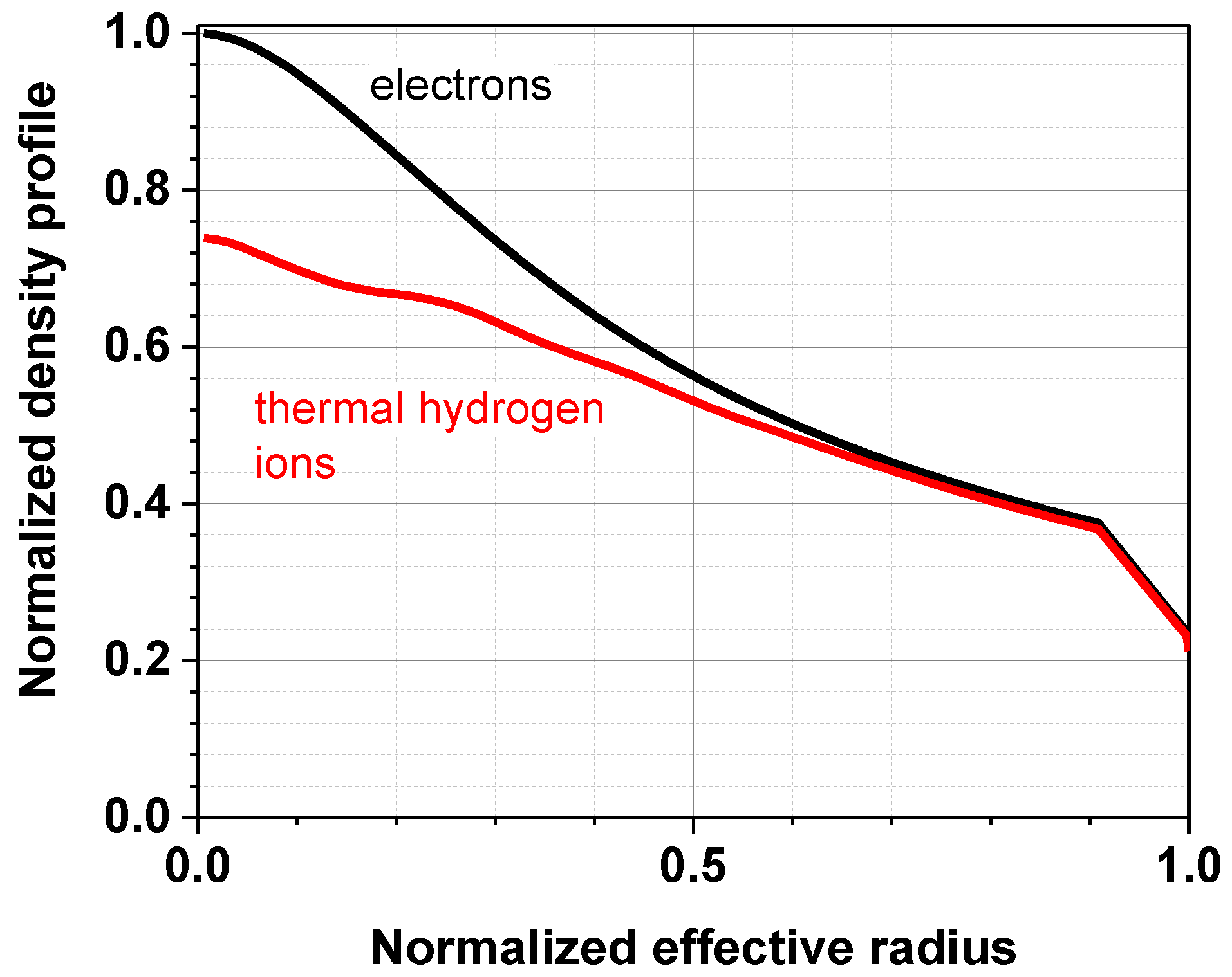
−3, which, together with the variation of the diffusivity, determines the possible range of the fluxes in the FC. The plasma density profile is then determined by the electron heat conductivity together with the particle sources from the gas influx across the separatrix, pellet injection, and NBI. The gas influx is calculated in the SOLPS code, and the profile of the corresponding ion source is calculated in ASTRA and depends on the density and temperature profiles inside the separatrix. The radial profile of the ion source from the pellet injection is pre-defined, with the maximum at some distance from the separatrix and the magnitude as the external parameter. The radial profile of the ion source from the neutral beam is calculated with the NUBEAM code [
32] built in ASTRA. An example of the resulting density profile for a D beam case is shown in
Figure 1. No density profile difference between the D and D + T beam cases is observed in our calculations. Note that the density profile shape has a minor impact on the neutron yield that is dominated by the beam–plasma interaction.
The resulting dimensionless plasma parameters, such as the collisionality of ~0.02 and the normalized ion Larmor radius of ~0.03–0.04 in FNS-ST (with the central ion temperature of 6–8 keV), are not far from those in the shots from the database analyzed in [
30,
31], thus justifying the implementation of this transport model for FNS-ST.
We use the FC-FNS code developed at the NRC Kurchatov Institute (Russian Federation) to simulate the balance of particles in the core and divertor plasma (based on the results calculated by the ASTRA and SOLPS codes) as well as the flows in all fuel cycle systems (in steady-state mode) and, accordingly, the calculation of the T inventory in them. To calculate the T inventories at the facility site, the values are calculated for all fuel cycle systems (based on the physical principles of their operation, the calculated isotope fluxes, and their concentrations), including the starting storage (containing T at the time T breeding systems are stopped). Since no extended T breeding is planned at the facility, the “T inventory” characterizes the value both at the moment of starting the facility and at any other moment in time (not containing the time-integrated T accumulation value).
The FNS-ST parameters used for the FC simulations are shown in
Table 1. The calculations show that the neutron yield varies in the range expected for the project [
1]. Optimization of the hybrid blanket to obtain the required TBR at the corresponding neutron intensities is beyond the scope of this work and will be performed in the future.
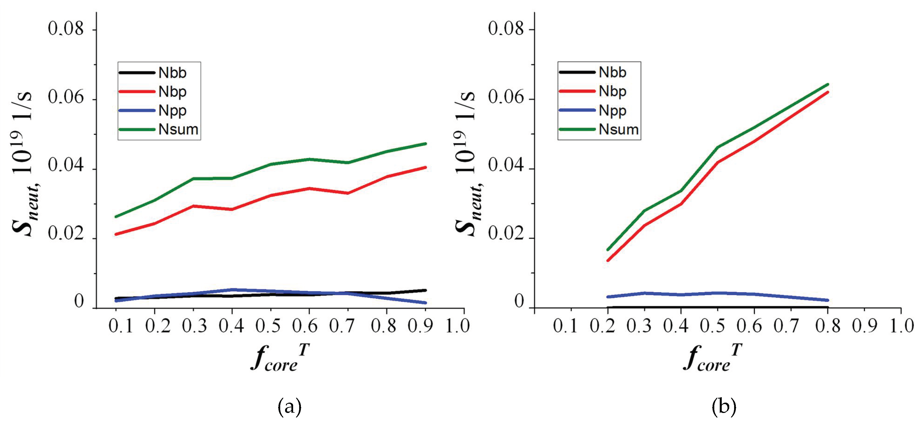
The NUBEAM-ASTRA calculations show that for both the D + T and D beams, an increase in the tritium fraction in the core plasma
fcore is beneficial for the neutron yield
Sneut. The simulation results are shown in
Figure 2. In the calculations with varying
fcore, the isotope composition of the D + T beam was taken unchanged such that
fNBT = 0.5.
In the FC-FNS code, the particle balance is described in the zero-dimensional approximation using the
SNB,
Spel, and
Ssep sources of the particles, assuming different lifetimes correlated with the ASTRA simulations [
25].
5. Discussion of Results
In
Figure 2, we can see that for the D + T beam, with an increasing fraction of tritium
fcoreT, the efficiency of neutron generation became higher. In the case of the D + T beam, the DT reaction occurs as a result of two processes: the interaction of the fast deuterium ions with the thermal tritium (process 1) and the interaction of the fast tritium ions with the thermal deuterium (process 2). In this case, an increase in the neutron yield of the reaction of the beam–plasma interaction (
Figure 2a,
Nbp) with an increasing fraction of tritium implies that the contribution of process 1 to the DT reaction considerably exceeds that of process 2. Note that when the fraction of tritium in the plasma is
fcoreT > 0.5 and the D beam is used, the neutron yield turns out to be higher (
Figure 2b). For both types of the beam, the fraction of tritium in the plasma
fcoreT can be different in different operating regimes (within the operating window of the
ne and
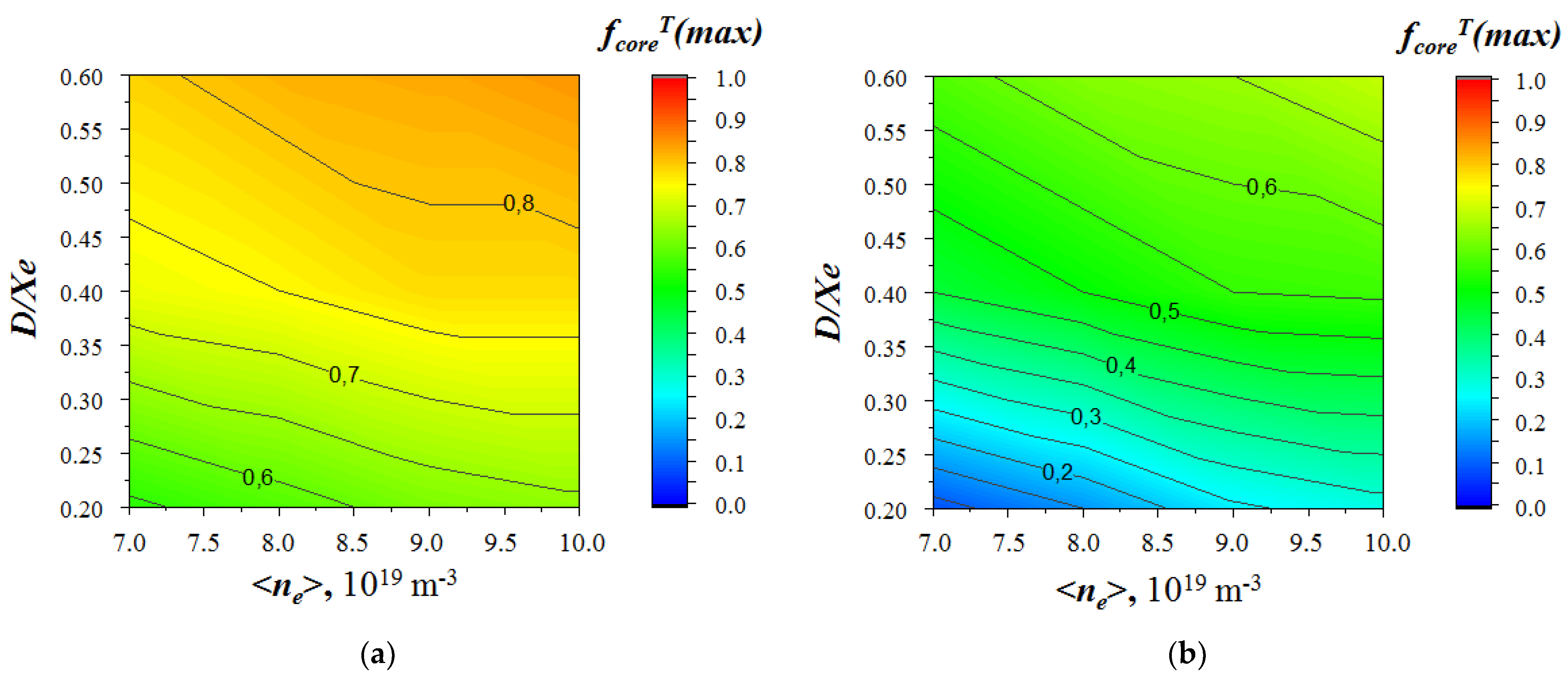
D/χe parameters) due to the considerable effect of the deuterium particle influx from the heating injectors on the isotope composition of the bulk plasma. For both types of the beam, the maximum possible neutron yield is reached at the maximum possible fraction of tritium in the plasma
fcoreT(max) (see
Figure 2). In this case, the pellets injected into the plasma consist of pure tritium (
SpelD = 0). The parameter
fcoreT(max) as a function of the
ne and
D/χe parameters is shown in
Figure 3. For the D beam, in the ranges of low densities
ne = 7.0−9.0 × 10
19 m
−3 and
D/χe = 0.2–0.3, the small values of
fcoreT(max) can be explained by the low flux
Spel and, therefore, by the considerable effect of the
SNBD flux along with the
SpelT flux. Within the operating windows of the
ne and
D/χe parameters, the maximum possible fractions of tritium are 0.85 and 0.7 for the D + T (
fNBT = 0.5) and D beams, respectively.
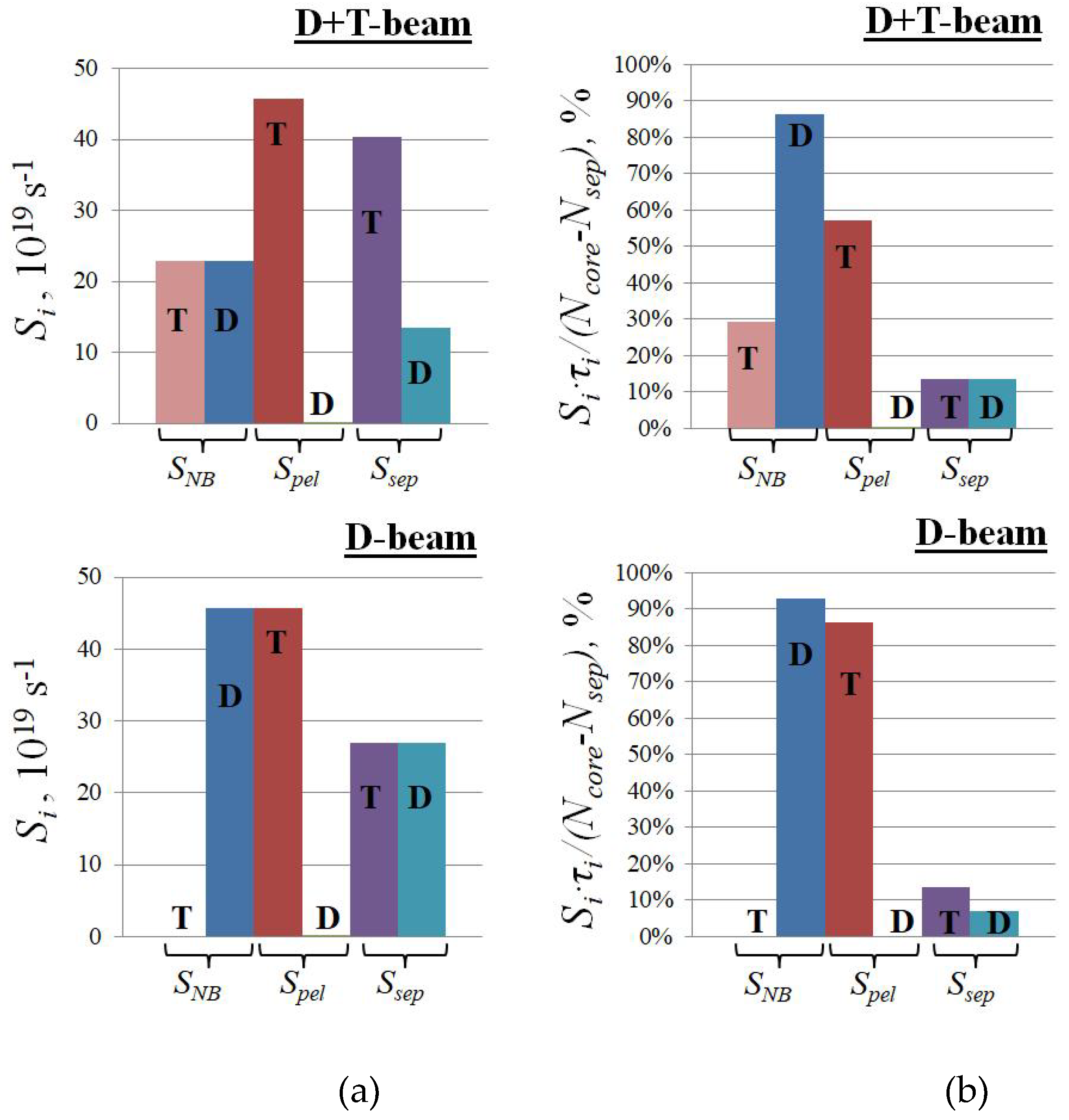
For the scenarios with the D + T and D beams with identical plasma parameters (
ne = 8.0 × 10
19 m
−3 and
D/χe = 0.4) but different fractions of tritium
fcoreT (0.75 and 0.5, respectively), the absolute values of the
SNB,
Spel, and
Ssep fluxes are shown in
Figure 4a. The contributions of these sources to the total number of particles, with allowance for different particle lifetimes for each source, are shown in
Figure 4b. It can be seen that a rather large particle flux
Ssep from the divertor region (
Figure 4a) makes a minor contribution to the total number of particles (
Figure 4b). This can be explained by the peripheral localization of this source and, accordingly, by the short lifetime of the particles coming from it. In this case, in the range of the
ne and
D/χe parameters under consideration, the total flux
SpelD +
SpelT varies in the range of ~10
20–10
21 s
−1.
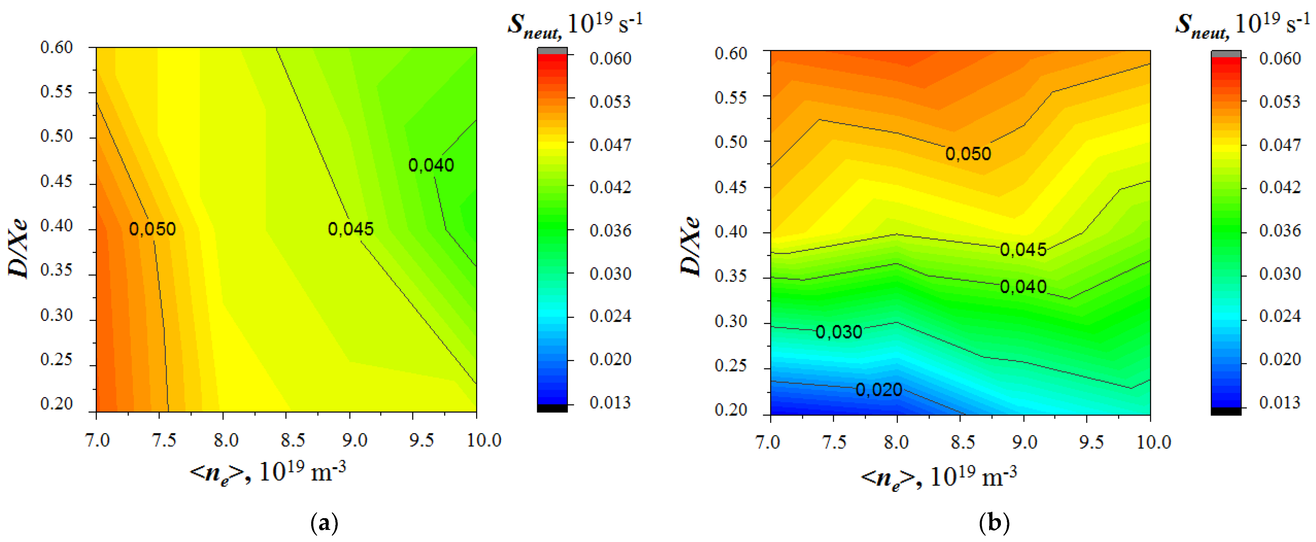
For both types of beams, the
Sneut intensities as functions of the
ne and
D/χe parameters are shown in
Figure 5. In this case, the fractions of tritium are maximal,
fcoreT = fcoreT(max), which provides the maximum possible neutron yield in the entire range of the parameters under consideration. It can be seen that the dependencies of the
Sneut intensities on the parameters are different for the scenarios with the D + T and D beams (see
Figure 5a,b). In this case, in the range of the tritium fractions
fcoreT(max) > 0.5, the ranges of neutron yield variation turn out to be comparable for both types of beams. However, the maximum values are reached in different ranges of the
ne and
D/χe parameters. For the D beam, the
Sneut intensity is noticeably lower compared with the D + T beam in the range of parameters where
fcoreT(max) < 0.5. This is an indirect consequence of the fact that the dependence
Sneut(fcoreT) shown in
Figure 2 for the central point of the parameter plane (
ne,
D/χe) is steeper for the D beam than for the D + T beam.
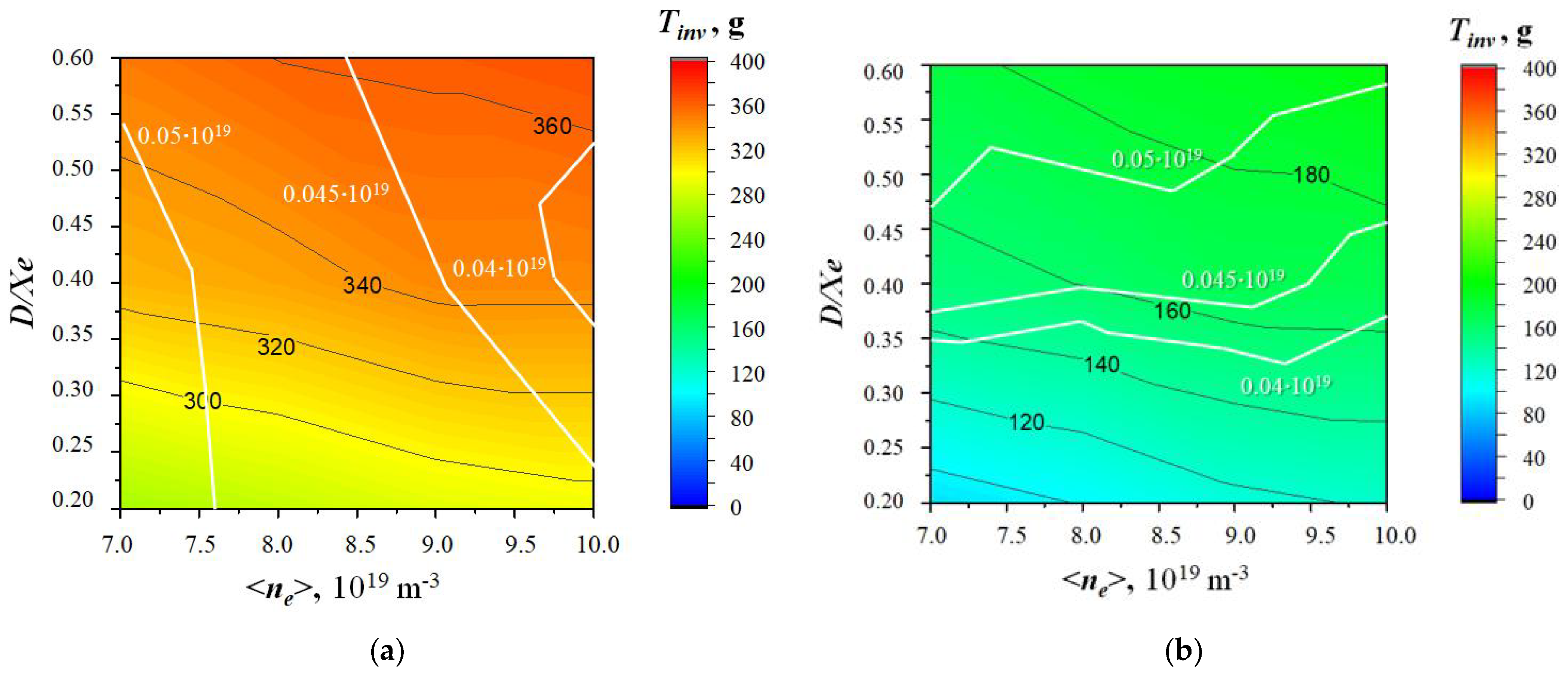
The amounts of tritium accumulated at the site as functions of the
ne and
D/χe parameters are shown in
Figure 6. For the D + T beam, the simulations of the operating regimes show that the amount of tritium accumulated in the FC of the facility is quite noticeable; nevertheless, it was lower than that estimated previously in [
4]. One can see that the accumulation of tritium in the FC depends directly on the fraction of tritium
fcoreT. For the D beam, the total amount of tritium turns out to be lower than for the D + T beam. Primarily, this is due to the absence of tritium in the neutral beam injectors (in the case of the D + T beam, each of them accumulates up to 100 g of T
2), as well as due to the smaller amount of tritium in the hydrogen isotope separation system.
By comparing
Figure 5 and
Figure 6, we can decide what regimes are most reasonable from the point of view of neutron generation and the amount of accumulated tritium at the site. For the D + T beam, to obtain the maximum neutron yield of 4.5–5.5 × 10
17 s
−1, it would be required to operate in the low plasma density regimes with
ne = 7.0–8.5 × 10
19 m
−3. The maximum neutron yields are reached in the range of
D/χe = 0.2–0.4, corresponding to the good confinement of particles in the plasma. In this case, the amount of tritium accumulated in the FC can vary from 260 to 370 g. In the regimes with the highest neutron yields, the amount of accumulated tritium is 260–340 g. For the D beam, on the contrary, a maximum neutron yield of 4.5–5.5 × 10
17 s
−1 is observed over the entire density range under consideration,
ne = 7.0–10.0 × 10
19 m
−3, in the regimes with not very good particle confinement,
D/χe = 0.4–0.6. The amount of tritium in the FC ranges from 90 to 200 g. At the same time, in the range of
fcoreT(max) < 0.5, the use of the D beam may result in obtaining low neutron yields (2–4 times lower than the maximum one). However, this allows operating at the minimum tritium content at the site. For convenience, in
Figure 5, the white lines indicate the levels of equal intensity for the corresponding distribution of the
Sneut intensity.
6. Conclusions
A consistent approach was taken in simulations of the operating regimes of the FNS-ST facility. The simulations were performed using the SOLPS4.3 and ASTRA codes for different bulk plasma densities and diffusion particle diffusivities. For the cases of using the heating beams consisting of D + T or pure D atoms at the compact neutron source FNS-ST, the dependence of the FNS neutron yield on the fraction of tritium in the bulk plasma was analyzed for the first time. The consistent modeling using the FC-FNS code made it possible to calculate the required fluxes of the fuel components into the plasma, supplied by different injection systems (pellet injectors and fast atomic beams). For both types of the heating beams, in the window of the working parameters ne and D/χe, the maximum possible fraction of tritium in the bulk plasma was calculated, at which all deuterium particles were injected into the plasma with the beam. For the scenarios of using the D + T or D beams, the neutron yields were calculated as functions of the ne and D/χe parameters. For the regimes with the maximum neutron yields, the accumulation of tritium at the site (in the fuel cycle) was calculated for different types of heating beams.
It was shown that for the D + T beams, the maximum neutron yield of 4.5–5.5 × 10¹⁷ s−1 could be obtained at the bulk plasma density of ne = 7.0–8.5 × 10¹⁹ m−3. The maximum neutron yields were reached in the range of D/χe = 0.2–0.4, corresponding to the good confinement of particles in the plasma. In this case, the amount of tritium accumulated in the FC of the facility is expected to range from 260 to 370 g, including up to 150 g accumulated in the neutral beam injectors.
For the D beam, the maximum neutron yield of 4.5–5.5 × 10¹⁷ s−1 corresponded to the density range of ne = 7.0–10.0 × 10¹⁹ m−3 in the regimes with not very good particle confinement, D/χe = 0.4–0.6. The expected amount of tritium in the FC ranged from 90 to 200 g. At the same time, in the range of the tritium fraction fcoreT(max) < 0.5, the use of the D beam may result in low neutron yields (2–4 times lower than the maximum one), although it provides the minimum tritium content at the facility site.
Based on the above estimates, we conclude that in the density range of ne = 7.0–10.0 × 10¹⁹ m−3, the use of the D beam is more reasonable. First of all, this is due to the lower tritium inventory in the FC, technical advantages associated with the absence of tritium in the injectors, and the corresponding less strict safety requirements for the operation of the injection system for plasma heating. In this case, the neutron intensities comparable in magnitude with the maximum ones (which is the priority issue for the fusion neutron source) for the D + T beam can be obtained in a wider range of plasma densities. We note that the range of parameters favorable for using the D beam corresponds to somewhat worse confinement of particles in the bulk plasma, which reduces the D ion density in the core and, correspondingly, increases fcoreT(max).


