Article

Time-Domain Dynamic Modeling and Analysis of Complex Heavy-Duty Gearbox Considering Floating Effect

State Key Laboratory of Digital Manufacturing Equipment and Technology, Huazhong University of Science and Technology, 1037 Luoyu Road, Wuhan 430074, China
*
Author to whom correspondence should be addressed.
Appl. Sci. 2021, 11(15), 6876; https://doi.org/10.3390/app11156876
Submission received: 30 June 2021 / Revised: 17 July 2021 / Accepted: 24 July 2021 / Published: 26 July 2021
(This article belongs to the Special Issue Modeling, Design and Control of Electric Machines)

Abstract

:

Featured Application

The proposed time-domain dynamic modeling method can be applied to analysis and design of heavy-duty gearboxes in wind turbines, cranes, drilling rigs and so on.

Abstract

Expert insights into the time-domain dynamic behavior of heavy-duty gearboxes form the foundations of design evaluation and improvement. However, in the existing lateral–torsional coupling (LTC) modeling method for gearboxes that is normally used for frequency-domain dynamic behavior, the meshing forces are modeled as spring dampers with fixed acting points on the meshing gears to simulate only the transient LTC effect, and thus the steady state characteristic in the time domain cannot be obtained due to the unrealistic distortion of positions and orientations as the gear angles increase. In this paper, a novel and generally applicable LTC modeling method for heavy-duty gearboxes, mainly planetary gear sets with floating components, is proposed by using space-fixed spring dampers with floating acting points on the meshing gears to study the time-domain dynamic response and to support the dynamic design of heavy-duty gearboxes. Based on the proposed method, a LTC model of a 2 megawatt (MW) wind turbine gearbox with floating components considering the time-varying meshing stiffness, bearing stiffness, torsional stiffness, and floating effect was established. The simulated results of representative components were in accordance with experimental results on a test rig, and dynamic behavior was calculated.

1. Introduction

Gear systems are the most significant and extensively adopted mechanical transmission devices in modern applications such as automobile, locomotive, mining, metallurgy, electric power, petroleum and chemical industries. As mechanical equipment tends to develop in the direction of larger scale and higher performance, gear systems with high power, high speed and heavy load are in great demand. The working environment for gear transmission systems is extremely complex, especially for the heavy-duty gearboxes adopted in large ships, offshore platforms, wind power machines, etc. There exist not only external incentives introduced by the variable load condition and power plant, but also internal incentives from the time-varying meshing stiffness, the gear transmission error, the meshing impact, etc. Taking the wind turbine gearbox (WTG) as an example, as the drivetrain that connects the rotor hub with the generator converts the wind energy into electrical energy, the wind field turbulence through the hub and the electricity grid disturbance through the generator become the external excitations [1]. Meanwhile, since most WTGs contain planetary gear sets with floating components because of the advantages of compact structure, high power density, and coaxial arrangement of transmission shafts [2], the varying mesh stiffness, meshing incentive, impact of floating components, and composition error generate the internal excitations [3,4]. These make the service condition of WTGs quite unique and rigorous. The service life of a wind turbine is usually designed to last more than 20 years [5]. However, internal WTGs have the highest failure rate of all wind turbine components [6,7], and the main cause of wind turbine standstill is the vibration issue [8]. Hence, the dynamic behavior and working performance of gearboxes have a significant impact on the whole machine, and research on the vibration characteristics is critical to the design and redesign of gearboxes.
Considerable efforts have been made to give comprehensive insights into the dynamic behavior and vibration issues of gearboxes, especially of planetary gear sets [9,10]. Kahraman et al. [11] derived a time-varying dynamic model of a planetary transmission including the manufacturing error, assembly variation and time-varying stiffness. Lin and Parker et al. [12] developed an analytical lumped-parameter model of a planetary gear set and used it to investigate the natural frequencies and vibration modes. Abousleiman et al. [13,14] investigated the vibration behavior of a planetary gear set with an elastic ring gear and an elastic planet carrier. Chen and Shao [15] derived a mesh stiffness model of an internal gear pair with a tooth root crack in the ring gear based on the potential energy principle. Christopher et al. [16] proposed a finite element formulation for the dynamic response of gear pairs. Maláková et al. [17] analyzed the main influencing factors on the meshing stiffness, as changes in the stiffness are a significant source of noise and vibration. She also designed a non-circular gear transmission system with continuously changing gear ratio and studied its kinematical characteristics [18]. Girsang et al. [19] studied the dynamic response of a WTG by enhancing the capability of FAST (a wind turbine CAE tool) [20] through the integration of a gearbox model built using Simscape, which took into account excitations from both the wind field and the generator. Zhu et al. [21,22] used the lumped parameter method to study the dynamic behavior of a WTG with flexible pins and proved that the flexible pins can improve the load sharing ability. Park et al. [23] investigated the influence of non-torque loads on the dynamic behavior of planetary gears, including the loading distribution and loading sharing, and concluded that considering the non-torque load during the design stage is quite important to accurately determine the design load that will guarantee the service life of a WTG.
In large-scale mechanical systems, heavy-duty gearboxes with planetary gear sets are adopted extensively due to their unique advantages of high power density and high transmission ratio; however, this yields complex configurations and characteristic serving circumstances. Thus, more stringent design criteria are desired than for common industrial gearboxes, and the dynamic forces become the major limiting factor to achieving better performance [24]. In previous studies concerning gearboxes, the assessment of dynamic behavior is usually centered on the frequency domain. Hence, a study of dynamic behavior in the time domain becomes significant, as it can confirm the dynamic loading factors, which are usually chosen by experience from a manual according to the traditional design code for common gearboxes. In this paper, an appropriate and generally applicable modeling approach of heavy-duty gearboxes, mainly the planetary gear set, is proposed to investigate dynamic behavior in the time domain, and a LTC model of a 2 MW WTG was built in which the time-varying meshing stiffness, bearing stiffness, torsional stiffness, and floating factor were considered. The model was then verified by experiments on a test rig, and dynamic characteristics of the WTG were finally revealed on the verified model.

2. LTC Modeling Approach of Heavy-Duty Gearbox

To establish a dynamic model of a heavy-duty gearbox, modeling of a planetary gear set with floating components serves as the most basic as well as the most significant portion. This is mainly because common gear transmissions can be simplified or derived from planetary gear sets. Therefore, a planetary gear set model will be highlighted and introduced as a representative basis in this section.

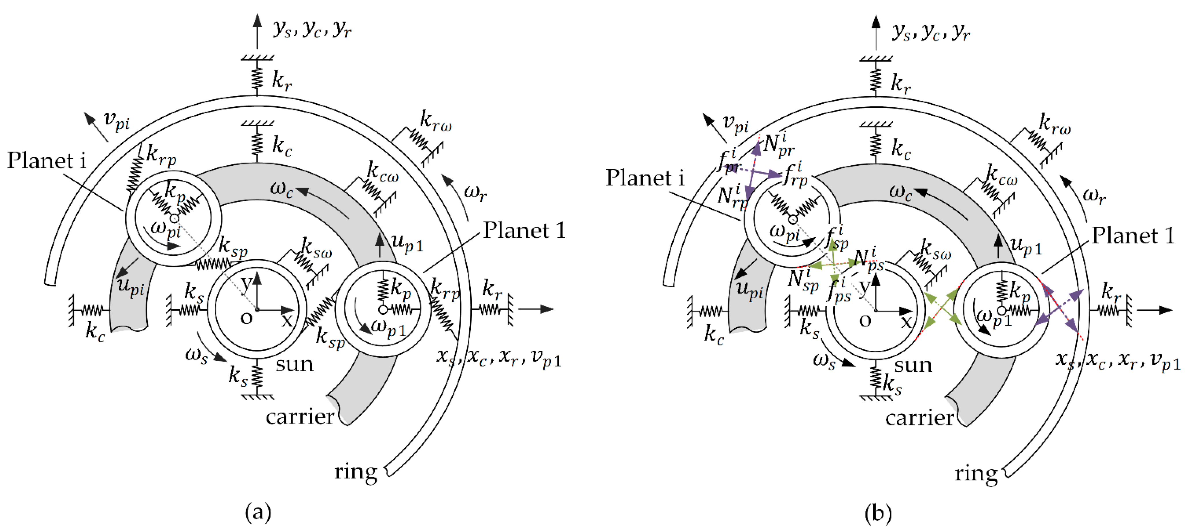
2.1. LTC Models of Planetary Gear Set

Interactive incentives between the gear engagements occur mainly through the meshing forces. The existing LTC model of a planetary gear set is shown in Figure 1a. The translation flexibility is simplified as linear spring dampers in the XY plane, while the flexibility between gear engagement, which is mainly caused by bending deflections and contact deformations of gear teeth, is simplified as a spring damper with equivalent average stiffness along the line of engagement with fixed acting points [12,15,25,26,27,28,29,30]. Thus, each component is modeled with three degrees of freedom (DOF), and the bearing stiffness and time-invariant meshing stiffness are considered. This method has an inherent defect in that only small angular displacements of gears are permitted, and thus only the transient vibration characteristic of gear pairs can be solved and obtained.
This paper proposes a novel method for LTC modeling. The elasticity and viscidity of gears, carriers, shafts, bearings, etc., are represented by time-varying stiffness–damping forces, while the bodies of gears, carriers and shafts are all modeled as rigid elements. Thus, a final multibody system of the gear set with consideration of time-varying stiffness, friction, damping, etc. is established. Based on Newton’s third law, the interaction of two bodies can be represented by an action force and an opposite reaction force that are functions related to the corresponding characteristic parameters of the two bodies. According to the basic law on parallel translation of force, forces on the contact point are equal to the combined effects of component force in XY plane and component torque around the Z axis in the center. With these proper transformations, the meshing effect can be modeled as a normal pressure force, represented by a time-varying stiffness spring damper force, and a tangential force, represented by a synthesis of a viscous damping force and a coulomb friction force (Figure 1b). These two kinds of force can eventually be replaced by time-varying component forces and torques with respect to the generalized coordinates on gear centers of the input and output gears respectively. Hence, large angular displacements of gears are allowed, and the entire coupling model can be utilized for the calculation of system dynamic behavior in the time domain.
The proposed method operates as space-fixed spring dampers with floating acting points, which guarantees that the positions and orientations of spring dampers coincide with the actual meshing forces regardless of changes in the centroids or the angles of the meshing gears. The proposed method is compared with the existing method in Table 1.

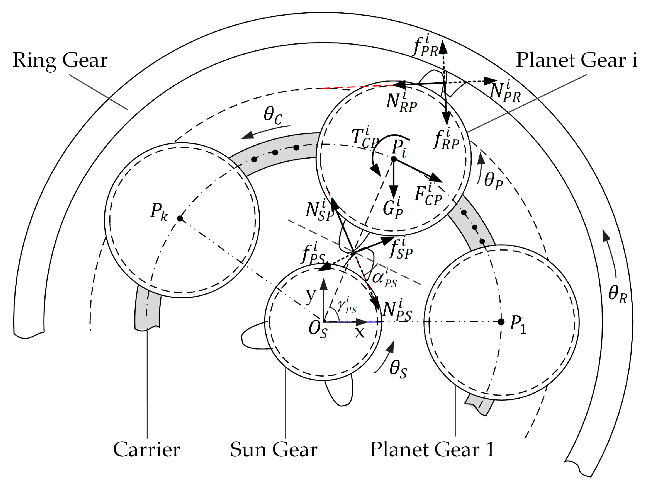
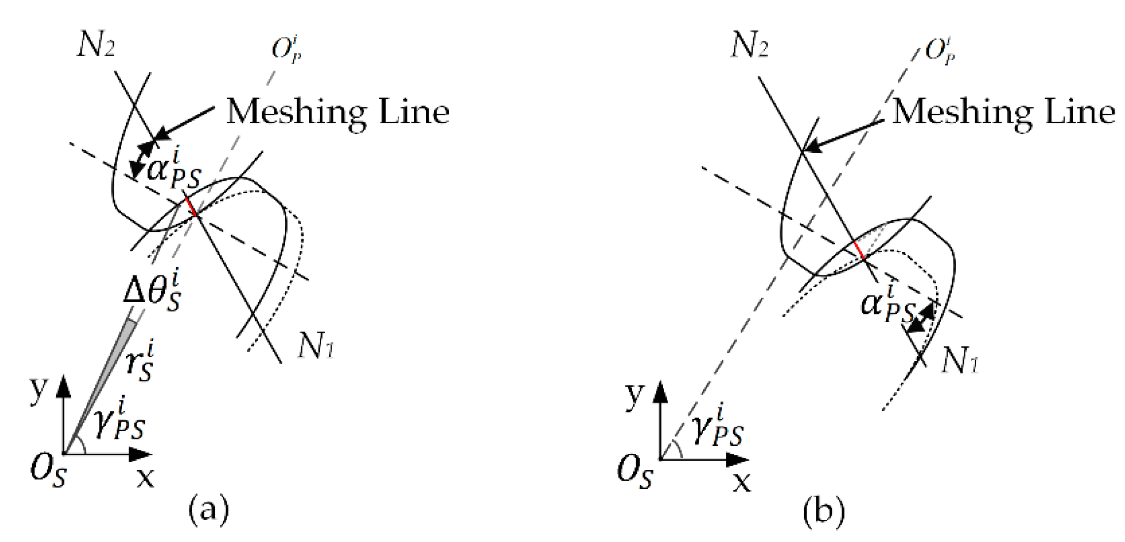
2.2. Detailed Formulations

Due to the unique status of the planetary gear set in heavy-duty gearboxes, detailed formulations of LTC dynamic equations of a planetary gear set with floating components are emphasized. Each object in the planetary gear set is modeled with three DOFs. The translational displacements and rotational angle are chosen as the generalized coordinates:
( x b , y b , θ b ) w h i l e , b = R , S   a n d   C ( x b i , y b i , θ b i ) w h i l e , b = P i   ( i = 1 , 2 , , n ) ,
in which R is the ring gear, P is the planet gear, S is the sun gear, and C is the planet carrier.
A schematic diagram of a force analysis of the whole gear set is shown in Figure 2. The reaction forces on the ith planet gear include N R P i and f R P i , the normal pressure force and tangential force that the ring gear exerts; N S P i and f S P i , the normal pressure force and tangential force that the sun gear exerts; and F C P i and T C P i , the reaction force and reaction torque from the bearing. Force analyses of the ring gear and the sun gear can be presented in the same way, which consist of the meshing forces and the reaction bearing forces if they exist.

2.2.1. Force Derivation of the Engagement of the Sun and ith Planet Gears

The composite deformation in normal and tangent directions of a meshing can be obtained from the generalized displacements; thus, the normal force N and tangent force f are derived. As shown in Figure 3, two main influencing factors exist: the difference between the actual and the ideal angle, and the time-varying center distance between the sun and planet gear that is mainly introduced by the floating components.
Under the ideal condition where the deformations of bearings and gear teeth are not considered, the movement of the ith planet and the sun gear can be regarded as fixed-axis rotation. The angles fit a transmission ratio equation as follows:
( θ P i Δ γ P S i ) Z P + ( θ S Δ γ P S i ) Z S = 0 ,
where γ P S i = arctan [ ( y P i y S ) / ( x P i x S ) ] is the time-varying position angle between the center connection line O P i O S and X axis, Δ γ P S i = γ P S i γ P S 0 i , and Z denotes the tooth number.
However, when considering the flexibility of the gear body, the deflection of gear teeth and the deformation of gear contact, the preceding equation does not fit anymore. The ideal angle θ P P S i of the planet gear under the condition of a rotation angle θ S and a position angle Δ γ P S i is
θ P P S i = ( θ S Δ γ P S i ) Z S / Z P + Δ γ P S i .
As a result, the angle difference Δ θ P P S i with respect to the ith planet gear is
Δ θ P P S i = θ P i θ P P S i .
The linear deformation caused by this angle difference is
δ θ n P S i = r P P S i tan Δ θ P P S i cos α P S i ,
where r P P S i = d P S i Z P / ( Z S + Z P ) is the pitch radius of the ith planet gear, which is time-varying during the meshing process and can be derived from the center distance d P S i = [ ( x P i x S ) 2 + ( y P i y S ) 2 ] 1 / 2 , and α P S i in the equation is the engagement angle: α P S i = arccos [ ( r P b + r S b ) / d P S i ] .
As shown in Figure 3b, Δ d P S i = d P S i d P S 0 i , which denotes the center distance variation of d P S i , is another crucial factor in calculating the composite deformation. The linear deformation caused by the variation of center distance is
δ d n P S i = Δ d P S i sin α P S i .
The normal composite deformation of the equivalent spring damper between the planet and sun gears is therefore given by
δ n P S i = δ θ n P S i + δ d n P S i = r P P S i tan Δ θ P P S i cos α P S i Δ d P S i sin α P S i .
The tangent composite deformation that is mainly caused by variation in center distance can be represented as
δ t P S i = Δ d P S i cos α P S i .
Furthermore, during the gear meshing process, the stiffness of an equivalent spring damper varies with changes in the gear meshing pair number, which toggles between 1 and 2 for a spur gear and is larger for a helical gear. According to the parameter identification of gear meshing stiffness, the relationship between the single pair and double pair gear meshing stiffness can be represented by a coefficient ξ (generally 1 < ξ < 2). Starting from the moment that a single meshing begins, the time-varying meshing stiffness in one cycle is
k P S = { k 0 θ ( 2 ε )   θ T ξ k ( 2 ε )   θ T < θ θ T ,
where θ is the meshing phase angle, and θ T is the cycle phase angle.
In addition, exchanges between the single and double pair of different planet-sun gear pairs are asynchronous during the process of loading sharing. Thus, the initial phase angles φ i representing the meshing state are introduced. Supposing that the total number of planets is n, and under the premise that design, manufacturing and assembly errors are ignored, the initial phase angle of an ith planet gear that is different from the adjacent one is
φ i = ( n 1 ) φ S 0  &  φ S 0 = [ Z S n int ( Z S n ) ] 2 π Z S .
Thus, the time-varying meshing stiffness of the ith planet-sun gear meshing pair is
k P S i = { k ( i 1 ) φ S 0 θ ( i 1 ) φ S 0 + ( 2 ε )    θ T ξ k 0 < θ < ( i 1 ) φ S 0 o r ( i 1 ) φ S 0 + ( 2 ε )    θ T < θ θ T .
Based on the above derivations of the time-varying stiffness and composite deformations in the normal and tangent directions, the normal force exerted on the ith planet gear by the sun gear in Figure 2 is calculated as
N S P i = k P S i δ n P S i = k P S i [ Z P ( r P b + r S b ) Z S + Z P tan ( θ P i + Z S Z P θ S i Z S + Z P Z P Δ γ P S i ) ( d P S i d P S 0 i ) sin α P S i ] .
The direction of this force is tangent to the base circle of the planet gear. The angle between it and the X axis is
β S P N i = π / 2 + γ S P i α P S i .
The tangent friction force between the planet and sun gear is composed of the viscous damping and coulomb friction forces:
f S P i = ( μ P S N S P i + c P S δ ˙ t P S i ) sgn ( δ ˙ t P S i ) .
In this equation, μ P S is the coulomb friction coefficient, c P S is the viscous damping coefficient, and sgn (x) is the sign function.
The tangent friction force is perpendicular to the normal force, direction of which is opposite to the direction of the relative sliding velocity. The angle between it and the X axis is
β S P f i = γ S P i α P S i .

2.2.2. Force Derivation of the Engagement of the Ring and ith Planet Gear

Analysis procedures to derive the force between the ring and ith planet gears are similar to the analysis procedures for that between the sun and ith planet gears. The difference is mainly concentrated in a small fluctuation in meshing stiffness between the ring and planet gear due to the high contact ratio, such that meshing stiffness can be regarded as a constant in some situations, which will be proved via parameter identification results in a later section.
The center distance of the ith planet and ring gear is
d P R i = ( x P i x R ) 2 + ( y P i y R ) 2 .
The time-varying position angle between the center connection line and the X axis is
γ P R i = arctan [ ( y P i y R ) / ( x P i x R ) ]  &  Δ γ P R i = γ P R i γ P R 0 i .
Under the ideal condition, the rotational angles fit a transmission ratio equation as follows:
( θ P i Δ γ P R i ) Z P ( θ R Δ γ P R i ) Z R = 0 .
The ideal angle θ P P R i of a planet gear under the condition of rotation angle of θ R and Δ γ P R i is
θ P P R i = ( θ R Δ γ P R i ) Z R / Z P + Δ γ P R i .
As a result, the angle difference Δ θ P P R i with respect to the ith planet gear is
Δ θ P P R i = θ P i θ P P R i .
The linear deformation caused by the angle difference is
δ θ n P R i = r P P R i tan Δ θ P P R i cos α P R i ,
where α P R i is the engagement angle and r P P R i is the time-varying pitch radius of the ith planet gear, which can be derived from the center distance d P R i , r P P R i = d P R i Z P / ( Z R Z P ) .
The linear deformation caused by the variation in center distance is
δ d n P R i = Δ d P R i sin α P R i .
Thus, the equivalent normal composite deformation of the spring damper between the ring and ith planet gears is
δ n P R i = δ θ n P R i + δ d n P R i = r P P R i tan Δ θ P P R i cos α P R i + Δ d P R i sin α P R i .
As in the previous section, the tangent deformation mainly caused by variation in center distance between the ring and planet gear is
δ t P R i = Δ d P R i cos α P R i .
k P R denotes the equivalent meshing stiffness of the ring and planet gears, and the fluctuation its value can be ignored. Based on the previous derivation of the deformation, the normal force on the ith planet gear can be computed as
N R P i = k P R δ n P R i = k P R [ Z P ( r R b r P b ) Z R Z P tan ( θ P i Z R Z P θ R i + Z R Z P Z P Δ γ P R i ) + ( d P R i d P R 0 i ) sin α P R i ] ,
Its direction is tangent to the base circle of the ith planet gear, and the angle between it and the X axis is
β R P N i = π / 2 + γ P R i + α P R i .
The tangent friction force f R P i between the ith planet gear and ring gear is composed of the viscous damping and coulomb friction forces:
f R P i = ( μ P R N R P i + c P R δ ˙ t P R i ) sgn ( δ ˙ t P R i ) ,
in which the definitions of μ P R , c P R and the function sgn(x) are almost the same as in the previous subsection.
The tangent friction force is perpendicular to the normal force, direction of which is opposite to the direction of relative sliding velocity. The angle between it and the X axis is
β R P f i = π + γ P R i + α P R i .

2.2.3. Bearing Force Analysis between Carrier and ith Planet Gear

The interaction between the carrier and the planet gear can be represented using an equivalent spring damper force and a friction torque. R P denotes the distribution radius of the planets, and γ C P 0 i is the initial distribution angle, namely the angle between the center line of the ith planet and the carrier along the X axis. As such, the deformation of the ith planet relative to the carrier is
δ C P x i = x P i [ x C + R P cos ( θ C + γ C P 0 i ) ]  &  δ C P y i = y P i [ y C + R P cos ( θ C + γ C P 0 i ) ] .
The rotational angle of the ith planet relative to the carrier is δ C P θ i = θ P i θ C . Therefore, the reaction force and torque on the center of the ith planet are computed as follows:
F C P x i = k C P B δ C P x i F C P y i = k C P B δ C P y i T C P z i = ( μ C P B F C P x i 2 + F C P y i 2 d C P B / 2 + c C P B δ ˙ C P θ i ) sgn ( δ ˙ C P θ i ) ,
where k C P B is the bearing stiffness, d C P B is the nominal diameter of bearings, μ C P B is the coulomb friction coefficient, and c C P B is the viscous damping coefficient.

2.2.4. System Dynamic Equations

To construct the sun gear dynamic equations, supposing that k S B and c S B are the bearing stiffness and the rotational viscous damping coefficient of the sun gear bearing if it exists, respectively, and that there exist n planet gears:
M S x ¨ S + k S B x S i = 1 n ( N P S x i + f P S x i ) = F S x M S y ¨ S + k S B y S i = 1 n ( N P S y i + f P S y i ) = F S y + G S I S θ ¨ S + c S B θ ˙ S i = 1 n ( T P S N i + T P S f i ) = T S .
F x , F y and T in Equations (31)–(38) are the external forces and torque respectively, values of which are considered zeroes if they do not exist. Substituting the specific formulas of N P S i , f P S i and T P S i , the sun gear dynamic equations can be rewritten as
M S x ¨ S + k S B x S + i = 1 n { N P S i [ sin ( γ S P i α S P i ) + μ P S cos ( γ S P i α S P i ) ] + c P S d P S 0 i ( r P b + r S b ) d P S i 2 d ˙ P S i cos ( γ S P i α S P i ) } = F S x M S y ¨ S + k S B y S + i = 1 n { N P S i [ cos ( γ S P i α S P i ) + μ P S sin ( α S P i γ S P i ) ] + c P S d P S 0 i ( r P b + r S b ) d P S i 2 d ˙ P S i cos ( α S P i γ S P i ) } = F S y I S θ ¨ S + c S B θ ˙ S + i = 1 n { N P S i [ r S b μ P S Z S Z S + Z P d P S i sin α P S i ] c P S Z S d P S 0 ( r P b + r S b ) ( Z S + Z P ) d P S i sin α P S i d P S i } = T S .
For the ring gear, the dynamic equations derivation process is similar. k R B and c R B are assumed to be the ring bearing stiffness and the rotational viscous damping coefficient if they exist, respectively.
M R x ¨ R + k R B x R i = 1 n ( N P R x i + f P R x i ) = F R x M R y ¨ R + k R B y R i = 1 n ( N P R y i + f P R y i ) = F R y + G R I R θ ¨ R + c R B θ ˙ R i = 1 n ( T P R N i + T P R f i ) = T R .
Plugging in the corresponding terms, the equations can be rewritten as
M R x ¨ R + k R B x R + i = 1 n { N P R i × [ sin ( γ R P i + α R P i ) + μ P R cos ( γ R P i + α R P i ) ] + c P R d P R 0 i ( r P b + r R b ) d P R i 2 d ˙ P R i cos ( γ R P i + α R P i ) } = F R x M R y ¨ R + k R B y R + i = 1 n { N P R i × [ cos ( γ R P i + α R P i ) + μ P R sin ( α R P i + γ R P i ) ] + c P R d P R 0 i ( r P b + r R b ) d P R i 2 d ˙ P R i cos ( α R P i γ R P i ) } = F R y + G R I R θ ¨ R + c S B θ ˙ S + i = 1 n { N P R i × [ r R b + μ P R Z R Z R + Z P d P R i sin α P R i ] c P R Z R d P R 0 ( r P b + r R b ) ( Z R + Z P ) d P R i sin α P R i × d P R i } = T R .
For the ith planet gear, as the applied forces on it include the engaging forces from the ring and sun gear and the bearing force, its dynamic equations are given by
M P x ¨ P i + k C P B [ x P i x C R P cos ( θ C + γ C P 0 i ) ] N P S i [ sin ( γ S P i α S P i ) + μ P S cos ( γ S P i α S P i ) ] c P S d P S 0 i ( r P b + r S b ) d P S i 2 d ˙ P S i cos ( γ S P i α S P i ) N P R i [ sin ( γ R P i + α R P i ) + μ P R cos ( γ R P i + α R P i ) ] c P R d P R 0 i ( r P b + r R b ) d P R i 2 d ˙ P R i cos ( γ R P i + α R P i ) = 0 ,
M P y ¨ P i + k C P B [ y P i y C R P sin ( θ C + γ C P 0 i ) ] N P S i [ cos ( γ S P i α S P i ) + μ P S sin ( α S P i γ S P i ) ] c P S d P S 0 i ( r P b + r S b ) d P S i 2 d ˙ P S i cos ( α S P i γ S P i ) N P R i [ cos ( γ R P i + α R P i ) + μ P R sin ( α R P i + γ R P i ) ] + c P R d P R 0 i ( r P b + r R b ) d P R i 2 d ˙ P R i cos ( α R P i γ R P i ) = G P ,
I P i θ ¨ P i + c P B ( θ ˙ P i θ ˙ R ) N P S i [ r S b μ P S Z S Z S + Z P d P S i sin α P S i ] + c P S Z S d P S 0 ( r P b + r S b ) ( Z S + Z P ) d P S i sin α P S i d P S i N P R i [ r R b + μ P R Z R Z R + Z P d P R i sin α P R i ] + c P R Z R d P R 0 ( r P b + r R b ) ( Z R + Z P ) d P R i sin α P R i d P R i = 0 .
For the planet carrier, similarly, dynamic equations can be expressed as
M C x ¨ C k C P B i = 1 n [ x P i x C R P cos ( θ C + γ C P 0 i ) ] = F C x M C y ¨ C k C P B i = 1 n [ y P i y C R P sin ( θ C + γ C P 0 i ) ] = F C y + G P I c θ ¨ c + c p b ( θ ˙ r θ ˙ p i ) + k C P B i = 1 n [ x P i x C R P cos ( θ C + γ C P 0 i ) ( x P i x C ) ] k C P B i = 1 n [ y P i y C R P sin ( θ C + γ C P 0 i ) ( y P i y C ) ] = T c .

3. Dynamic Modeling of a WTG Test Rig

A full test rig which was used to test and evaluate the dynamic performance of a 2 MW WTG is introduced in this section. A LTC model considering specific structures of this WTG was constructed using the proposed modeling approach of a planetary gear set with floating components.

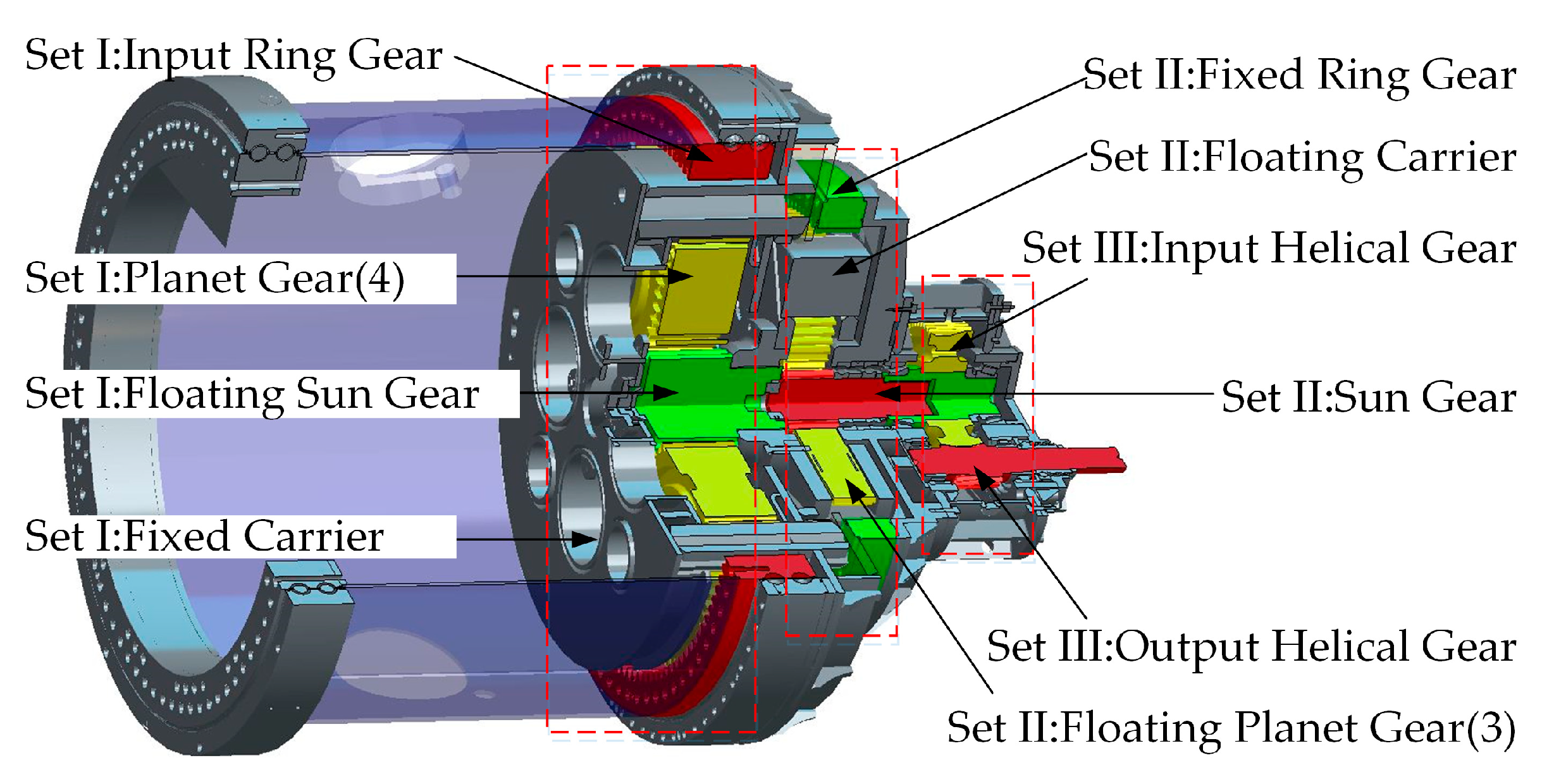
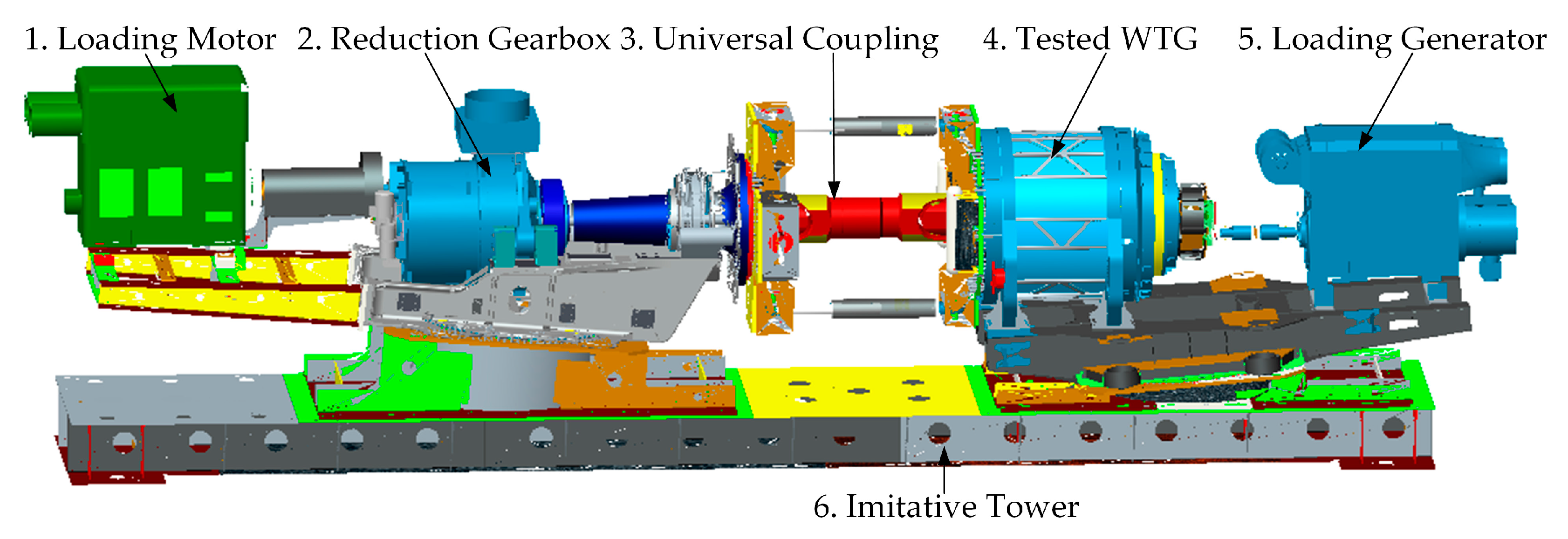
3.1. Structure of the Full Test Rig

The 2 MW WTG modeled is depicted in Figure 4. It primarily consists of three gear sets: a low-speed planetary gear set (LSP), a high-speed planetary gear set (HSP) and a parallel-shaft helical gear set (PSH). To reach the design objective of power dividing, the LSP had four transverse fixed planet gears and a floating sun gear, while the HSP had a fixed ring gear and a floating carrier with three planet gears affixed with bearings. The wind field excitation acted on the ring gear of the LSP, and the grid load from the electric generator acted on the output axis of the PSH. The intricate dynamics of the entire floating component, including the sun gear from the LSP, the carrier and three planet gears from the HSP, made this WTG quite distinct from common designed ones.
Figure 5 shows the 3D geometry model of the entire test rig. Part 1 is a loading motor, the speed of which was controlled, and part 2 is an auxiliary reduction gearbox. A combination of the two was utilized to imitate the wind input. Part 5 is a loading generator, the torque of which was controlled. Part 4 is the tested 2 MW WTG, which is connected with Part 2 through a universal coupling and with Part 5 through a flexible flange.

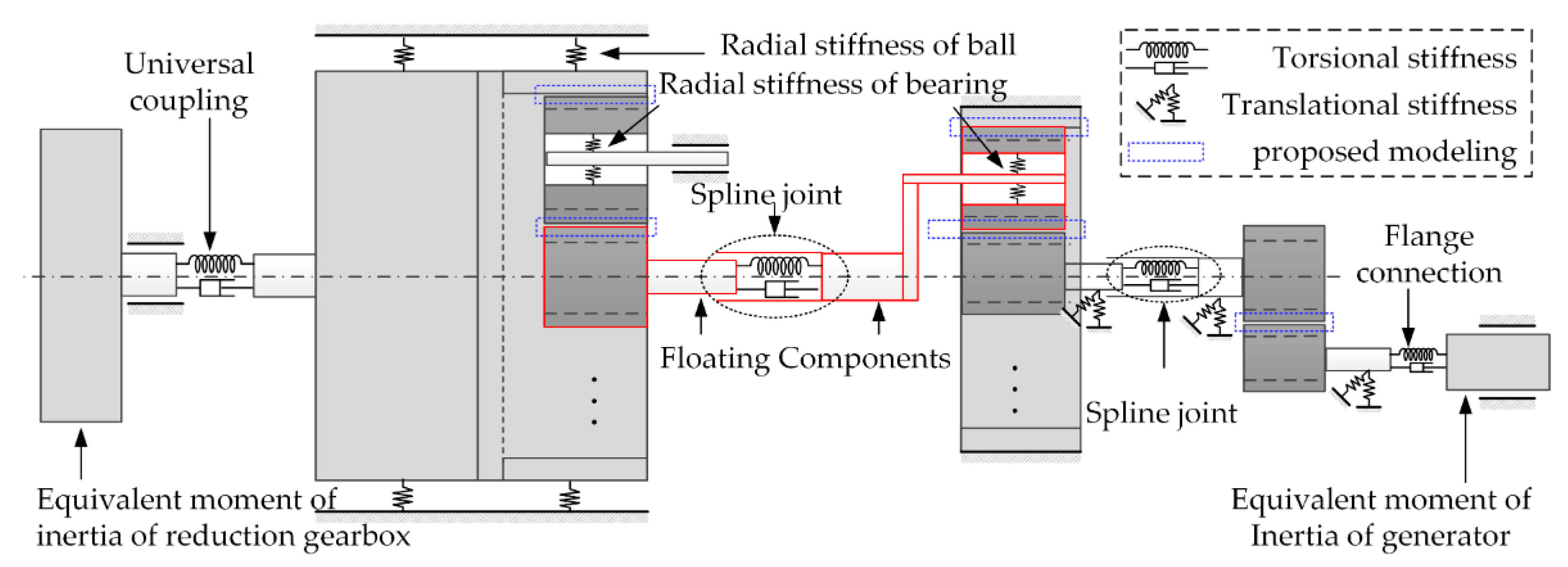
3.2. Dynamic Model of the Full Test Rig

A LTC model of the full test rig was constructed based on the proposed method in order to analyze the dynamic loading factors and dynamic behavior.
Figure 6 shows the schematic of the simplified LTC dynamic model of the full test rig. Not only the meshing effect but also the bearing flexibility and torsional elasticity of shafts and joints were considered. In the model, the gear meshing effects of the LSG and HSG gear sets were considered using the proposed method. The PSH was regarded as a spur gear set with high contact ratio under the condition that axial flexibility was not considered. The imitated wind input that combined a loading motor and a reduction gearbox was considered an excitation with rotational inertia, and the output generator was considered a torque loading with rotational inertia. In addition, torsional models of the spline connection, the universal coupling and the flange joint were built, and the radial stiffness of different bearings was included.
This proposed LTC model in Figure 6 was implemented with the aid of the MS. ADAMS software due to its superiority in calculation of multibody systems. In the simulated model, translational displacements and rotational angles of all components were acquired in real time. The time-varying deformations and relative velocities of the elastic elements in Figure 6 were calculated using the derived equations. The meshing forces of gears, torques of shafts, bearing forces, etc. were then also computed using the equations in Section 2, and finally acted on the corresponding components using the force function of ADAMS. It should also be noted that parameters like meshing stiffness were also time-varying according to the related switching conditions derived in Section 2.

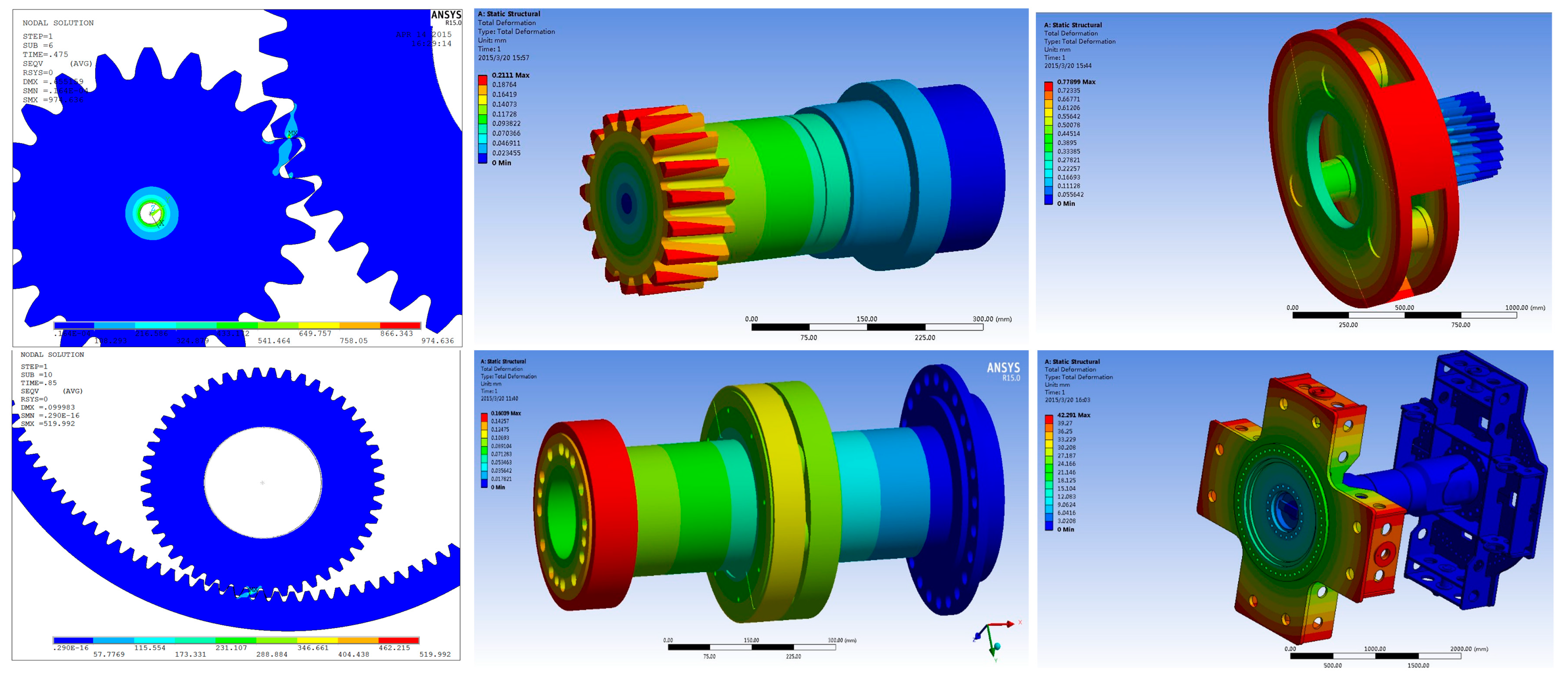
3.3. Parameter Identification of the Dynamic Model

Table 2 and Table 3 show the main design parameters of the LSP, HSP and PSH gear sets, based on which basic parameters of gears and gear pairs could be derived and calculated.
As shown in Figure 7, parameter identifications of the gear meshings, the connections and the shafts were conducted by means of Finite Element Analysis (FEA). In the process, the loading was increased gradually until reaching the service load, and the stiffness value was calculated as the slope of the nonlinear force-displacement curve on the operating point. For gear meshing, both the single and double pair contact situations were calculated. Detailed identification results are shown in Table 3, Table 4 and Table 5.
Parameter identification of the radial bearing stiffness was conducted in a similar way. The inner or outer ring was fixed while the other one was loaded until reaching the service load, and the bearing stiffness was calculated through the nonlinear relationship between loading force and relative radial displacement. Table 6 shows the identification results. With these identified parameters, dynamic behavior of the 2 MW WTG could be simulated.

4. Experimental Validation and Dynamic Analysis of the WTG

To demonstrate the validity of the novel proposed modeling method of heavy-duty gearboxes, experiments were conducted on the 2 MW WTG test rig specified in Figure 4 and Figure 5, and the experimental results were compared with the simulation results from the LTC model of the entire test rig under loading conditions identical to the rated working environment. Furthermore, dynamic loading factors of different gear sets, which are crucial to the design of WTG system, were calculated based on the LTC model that was verified by experiments.

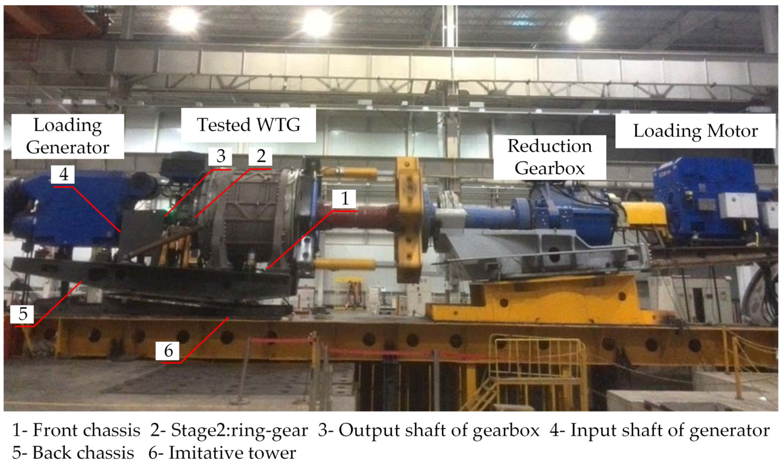
4.1. Configuration of the Full Test Rig

The experiments were conducted in a workshop of SANY (a wind power equipment company). The test rig was loaded according to the rated working condition of the 2 MW WTG: the rated rotating speed of the imitated wind input that combined the loading motor and the reduction gearbox was 15 rpm and the rated loading torque from the generator, acting on the PSH output axis, was 1.06 × 10⁴ N·m. Single-axis vibration acceleration sensors (PCB 352C34) were utilized to measure the vibration behavior of the WTG system, and the detailed position arrangement of sensors is shown in Figure 8. The data acquisition bandwidth was set to be 8192 Hz. Sensor signals were imported into a LMS SCADAS III data acquisition system, and the accompanying software LMS Test was employed for data processing and analysis. The simulation LTC dynamic model was loaded on the input equivalent moment of inertia progressively to a constant rotating speed of 15 rpm and on the output equivalent moment of inertia with an identical torque, to make sure that the loading conditions of the simulation and experiment WTG were identical. The variable stiffness coefficients of the three gear sets in the simulation model were set to be 1.1, 1.4 and 1.05, respectively, based on the identification results.

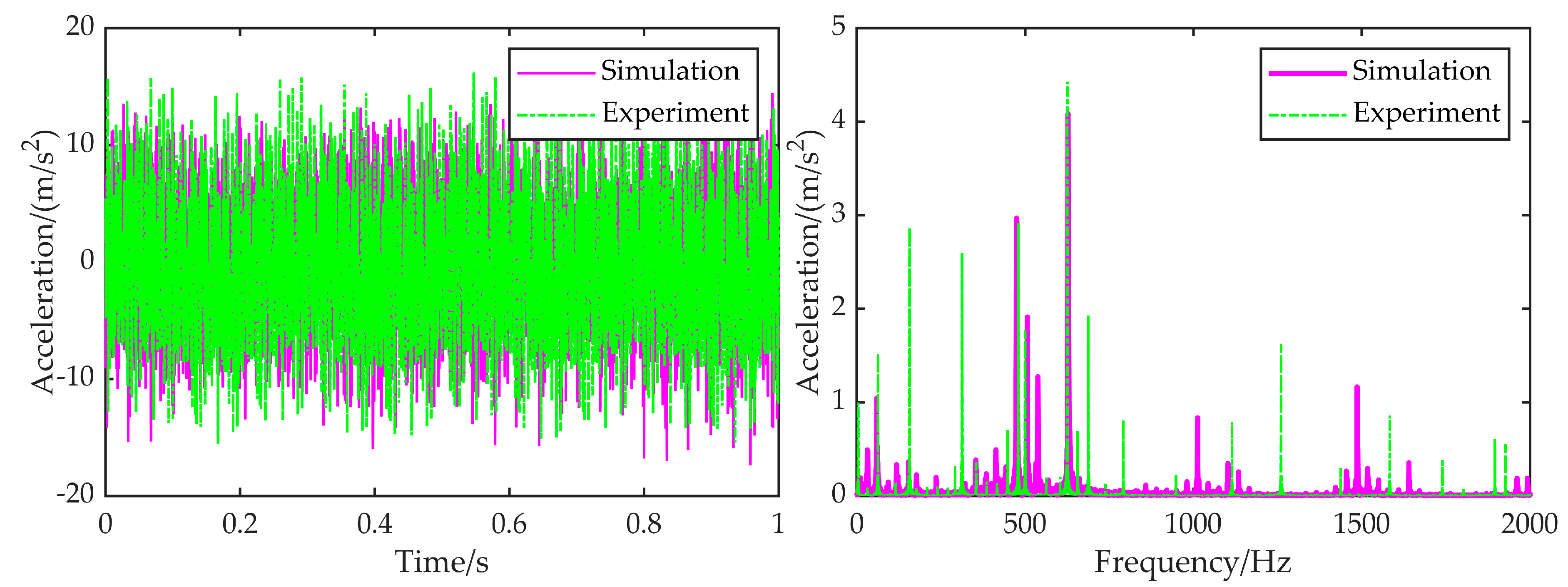
4.2. Comparison of the Simulated and Experimental Results

Based on the identified parameters and loading conditions, theoretical meshing frequencies of the tested WTG were computed through multiplying the rotating frequency by the tooth number. The results are listed in Table 7, and were 29.5 Hz, 158.2 Hz and 628.3 Hz, respectively.
Acceleration signals from the X and Y directions were synthesized to reveal the lateral vibration behavior of the full test rig. Figure 9 and Figure 10 are the comparison diagrams for the front chassis and the output shaft respectively, and Table 8 shows the comparison of the main frequency components of the experimental and simulated results from different locations on the entire WTG system.
Due to the time-varying stiffness, the gear meshing effect can be regarded as inner excitations to some extent, and thus the vibration characteristic of the entire system became complex, which can be identified from the abundant frequency components of both vibration spectra. Experimental frequencies from the front chassis mainly concentrated on 62.5 Hz, 114.4 Hz, 156.3 Hz, 312.5 Hz, 625 Hz, etc., while the main frequencies of the output shaft were 62.5 Hz, 156.3 Hz, 312.5 Hz, 479.1 Hz, 500.2 Hz, 625 Hz, etc. Detailed comparisons from the figures and tables show that the major frequency components and corresponding amplitudes of the experimental results were in accordance with the simulated ones; thus, validation of the dynamic modeling method and the WTG model is demonstrated.

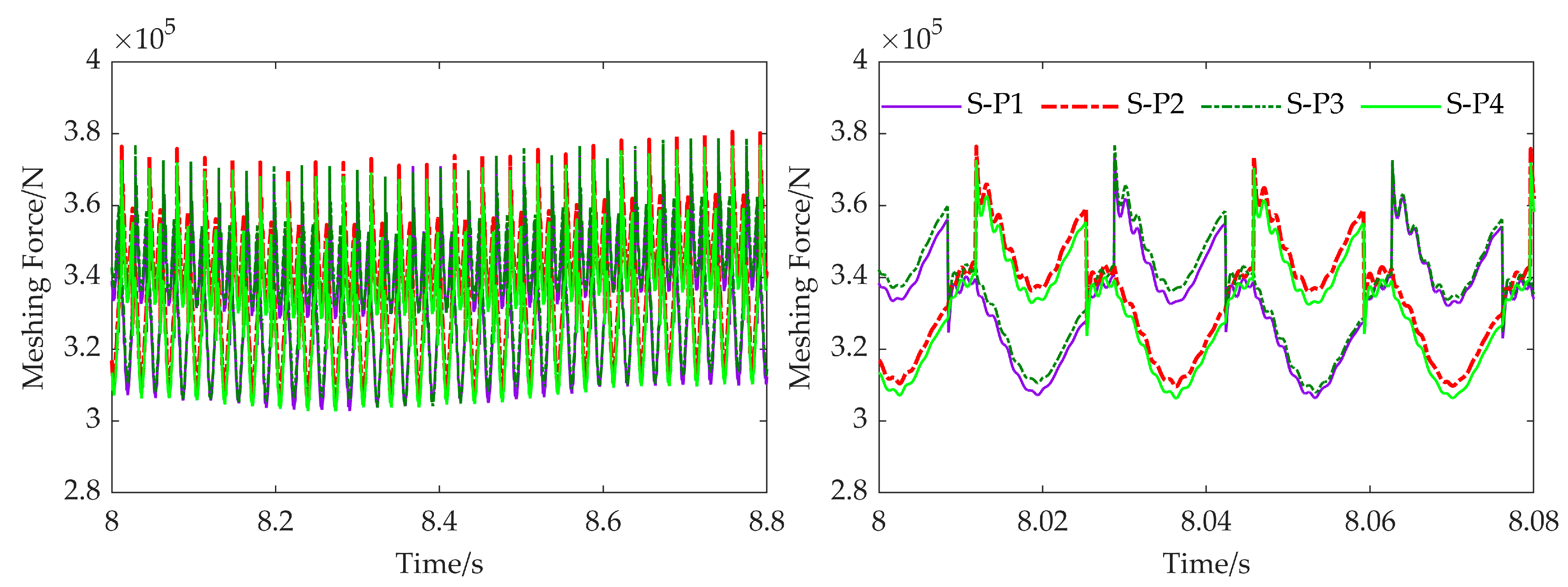
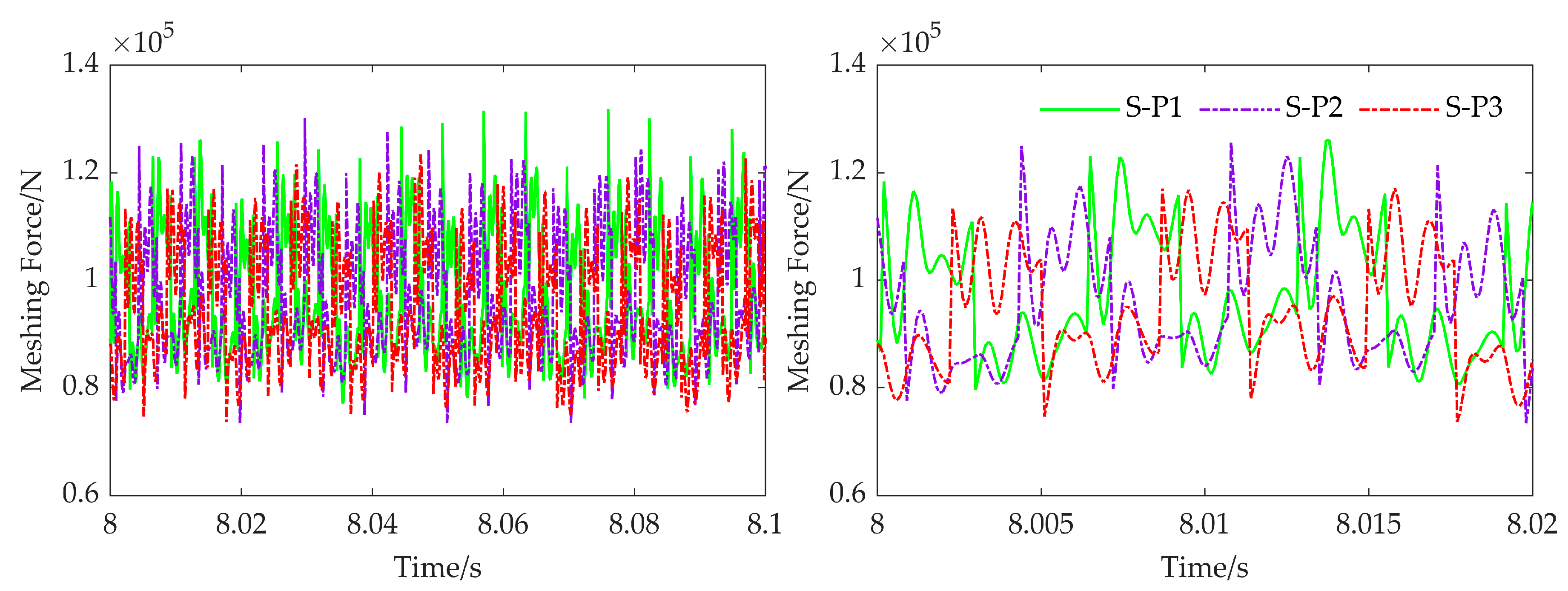
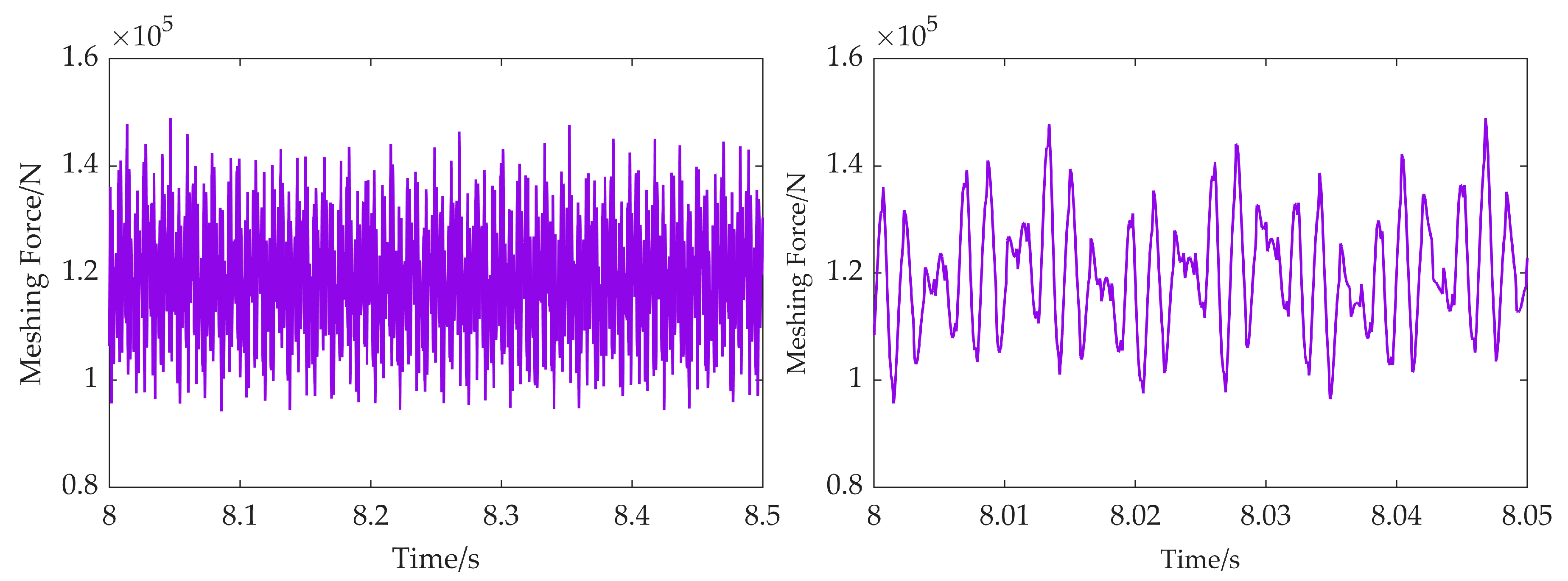
4.3. Time-Domain Dynamic Results of the WTG

Figure 11, Figure 12 and Figure 13 are the numerical time-domain dynamic meshing forces between the sun and planet gears of the LSP and HSP, and the meshing force of the PSH, respectively.
On this basis, the dynamic loading factors between gears, which are significant for the design stage, were calculated to be 1.12, 1.37 and 1.27 and are listed in Table 9. The results were different from the chosen factors of 1.02, 1.08, 1.07 obtained from an experiential manual. Under larger dynamic loadings that exceed the design limits, gear cracks may occur. Further dynamic examinations of the whole system in both the frequency and time domains can be conducted using the proposed method, while these examinations are beyond the scope of the existing method.

5. Conclusions

In this paper, a novel and generally applicable LTC modeling approach for calculating the dynamic behavior of heavy-duty gearboxes in the time domain with consideration of the floating effect, time-varying meshing stiffness, bearing stiffness, torsional stiffness, etc., is proposed. This approach is more comprehensive and apparently gives clearer insights into the time-domain dynamics of heavy-duty gearboxes, such as WTGs, than the existing method. Based on the proposed method, a LTC model of a full test rig was built, which was used to test a 2 MW WTG consisting of two planetary gear sets and a parallel-shaft helical gear set. Dynamic experiments were conducted on the test rig. Validity of the proposed method and the built model were demonstrated, as the simulated results were in accordance with the experimental results. According to the time-domain results of meshing forces in the verified model, larger dynamic loading factors than the designed ones chosen by a traditional empirical method were found. This means that gear damage may occur in actual working conditions and the built 2 MW WTG system must be redesigned and improved. In conclusion, the proposed method can give a new perspective on heavy-duty gearboxes that is preferable to the existing method, and can provide sufficient time-domain information to contribute to the design, evaluation and redesign of large-scale mechanical systems as represented by WTG systems.

Author Contributions

Conceptualization, J.W., W.J. and X.C.; Data curation, W.J.; Formal analysis, Y.Z.; Funding acquisition, W.J.; Investigation, J.W. and Y.Z.; Methodology, J.W., Y.Z. and W.J.; Project administration, X.C.; Resources, X.C.; Visualization, Y.Z.; Writing—original draft, J.W. All authors have read and agreed to the published version of the manuscript.

Funding

This work was supported by the National Key R&D Program of China (No.2020YFB2007301, No.2020YFB2007601), the National Natural Science Foundation of China (No.52075193), and the National Science and Technology Major Project of China (No.2017ZX02101007-002).

Institutional Review Board Statement

Not applicable.

Informed Consent Statement

Not applicable.

Data Availability Statement

Data are contained within the article.

Conflicts of Interest

The authors declare no conflict of interest.

Nomenclature

Symbol/AbbreviationDescription
LTCLateral-torsional coupling (model/modeling)
MWMegawatt
WTGWind turbine gearbox
DOFDegrees of freedom
LSPLow-speed planetary gear set
HSPHigh-speed planetary gear set
PSHParallel-shaft helical gear set
FEAFinite element analysis
x R , y R Translational displacements of the ring gear
x S , y S Translational displacements of the sun gear
x C , y C Translational displacements of the carrier
θ R , θ S , θ C Rotational angles of the ring gear, sun gear and carrier respectively
x P i , y P i , θ P i Translational displacements and rotational angle of the ith planet gear
N R P i , f R P i Normal pressure force and tangential force exerted on the ith planet gear by the ring gear
N S P i , f S P i Normal pressure force and tangential force exerted on the ith planet gear by the sun gear
F C P i , T C P i Reaction force and torque exerted on the ith planet gear by the bearing
O S , O P i , O R Center points of the sun gear, the ith planet gear, and the ring gear respectively
γ P S i Time-varying position angle between the center connection line O P i O S and the X axis
γ P S 0 i Inital position angle between the center connection line O P i O S and the X axis
Δ γ P S i Time-varying changing value of position angle γ P S i
Z S , Z P , Z R Tooth number of the sun gear, planet gear, and ring gear respectively
θ P P S i Ideal rotational angle of the ith planet gear under θ P
Δ θ P P S i Difference between the ideal and actual rotational angles of the ith planet gear
δ θ n P S i Linear deformation caused by angle difference Δ θ P P S i
d P S i Time-varying center distance between the ith planet gear and the sun gear
d P S 0 i Initial center distance between the ith planet gear and the sun gear
Δ d P S i Time-varying changing value of center distance d P S i
r P P S i Pitch radius of the ith planet gear while engaged with sun gear
α P S i Engagement angle between the ith planet gear and sun gear
r P b , r S b , r C b Radius of base circle of the planet gear, sun gear and ring gear respectively
δ d n P S i Linear deformation caused by variation of center distance Δ d P S i
δ n P S i Normal composite deformation between the ith planet and sun gear
δ t P S i Tangent composite deformation between the ith planet and sun gear
ξ Coefficient representing the double pair gear meshing stiffness with respect to single pair gear meshing stiffness
φ i Initial phase angle of the ith planet gear
φ S 0 Phase difference of adjacent planet gears into a single tooth meshing state
k P S i Time-varying meshing stiffness of the ith planet gear and sun gear
β S P N i Angle between the normal force N S P i and the X axis
μ P S Coulomb friction coefficient of the sun gear and planet gear
c P S Viscous damping coefficient of the sun gear and planet gear
β S P f i Angle between the tangent friction force f S P i and the X axis
d P R i Time-varying center distance between the ith planet gear and the ring gear
γ P R i Time-varying position angle between the center connection line O P i O R and the X axis
γ P R 0 i Inital position angle between the center connection line O P i O R and the X axis
Δ γ P R i Time-varying changing value of position angle γ P R i
θ P P R i Ideal rotational angle of the ith planet gear under θ R
Δ θ P P R i Angle difference between the ideal and actual rotational angles of the ith planet gear
δ θ n P R i Linear deformation caused by angle difference Δ θ P P R i
d P R i Time-varying center distance between the ith planet gear and the ring gear
d P R 0 i Initial center distance between the ith planet gear and the ring gear
Δ d P R i Time-varying changing value of center distance d P R i
r P P R i Pitch radius of the ith planet gear while engaged with ring gear
α P R i Engagement angle between the ith planet gear and ring gear
δ d n P R i Linear deformation caused by variation of center distance Δ d P R i
δ n P R i Normal composite deformation between the ith planet and ring gear
δ t P R i Tangent composite deformation between the ith planet and ring gear
k P R Meshing stiffness of the planet gear and sun gear
β R P N i Angle between the normal force N R P i and the X axis
μ P R Coefficient of coulomb friction of the ring gear and planet gear
c P R Viscous damping coefficient of between the ring gear and planet gear
β R P f i Angle between the tangent friction force f R P i and the X axis
R P Distribution radius of planet gears
γ C P 0 i Initial distribution angle of the ith planet gear
δ C P x i , δ C P y i Deformations of the ith planet relative to the carrier in X and Y directions respectively
δ C P θ i Rotational angle of the ith planet relative to the carrier
k C P B Translational stiffness of the bearings between carrier and planet gear
d C P B Nominal diameter of bearings between carrier and planet gear
μ C P B Coulomb friction coefficient of the bearings between carrier and planet gear
c C P B Viscous damping coefficient of the bearings between carrier and planet gear
k S B , c S B Bearing stiffness and rotational viscous damping coefficient of the sun gear bearing
k R B , c R B Bearing stiffness and rotational viscous damping coefficient of the ring gear bearing
M a , I a , G a   ( a = S , P , R , C ) Mass, inertia and gravity of the sun gear, planet gear, ring gear and carrier respectively
T a   ( a = S , R , C ) Torques on the sun gear, ring gear and carrier respectively

References

  1. Helsen, J.; Vandepitte, D.; Desmet, W. Flexible modelling of wind turbine gearboxes with special focus on shaft flexibilities. In Proceedings of the 10th International Conference on Recent Advances in Structural Dynamics (RASD) 2010, Southampton, UK, 12–14 July 2010. [Google Scholar]
  2. Tsai, S.; Hwang, G.; Yeh, S. An analytical approach for load sharing analysis of planetary gear drives. In Proceedings of the 13th World Congress in Mechanism and Machine Science, Guanajuato, Mexico, 19–23 June 2011; pp. 19–25. [Google Scholar]
  3. Leithead, W.; Rogers, M. Drive-train characteristics of constant speed HAWT’s: Part I—Representation by simple dynamic models. Wind Eng. 1996, 20, 149–174. [Google Scholar]
  4. Sicot, C.; Devinant, P.; Laverne, T.; Loyer, S.; Hureau, J. Experimental study of the effect of turbulence on horizontal axis wind turbine aerodynamics. Wind Energy 2006, 9, 361–370. [Google Scholar] [CrossRef]
  5. Lee, G.H.; Park, Y.J.; Kim, J.K.; Yim, J.G.; Nam, Y.Y.; Chong, T.H. An optimal design for MW-class wind turbine gearboxes based on their structural characteristics. In Proceedings of the 8th World Wind Energy Conference and Exhibition 2009, Jeju, Korea, 23–25 June 2009; pp. 101–109. [Google Scholar]
  6. Krouse, J. Wind turbine gearbox vibaration. Power Eng. 2009, 113, 16–17. [Google Scholar]
  7. Spinato, F.; Tavner, P.J.; van Bussel, G.J.W.; Koutoulakos, E. Reliability of wind turbine subassemblies. IET Renew. Power Gener. 2009, 3, 387–401. [Google Scholar] [CrossRef] [Green Version]
  8. Abderrazzaq, M.A.; Hahn, B. Analysis of the turbine standstill for a grid connected wind farm (case study). Renew. Energy 2006, 31, 89–104. [Google Scholar] [CrossRef]
  9. Liang, X.H.; Zuo, M.J.; Hoseini, M.R. Vibration signal modeling of a planetary gear set for tooth crack detection. Eng. Fail. Anal. 2015, 48, 185–200. [Google Scholar] [CrossRef]
  10. Li, M.; Xie, L.; Ding, L. Load sharing analysis and reliability prediction for planetary gear train of helicopter. Mech. Mach. Theory 2017, 115, 97–113. [Google Scholar] [CrossRef]
  11. Kahraman, A. Load sharing characteristics of planetary transmissions. Mech. Mach. Theory 1994, 29, 1151–1165. [Google Scholar] [CrossRef]
  12. Lin, J.; Parker, R.G. Analytical characterization of the unique properties of planetary gear free vibration. J. Vib. Acoust. 1999, 121, 316–321. [Google Scholar] [CrossRef]
  13. Abousleiman, V.; Velex, P. A hybrid 3D finite element/lumped parameter model for quasi-static and dynamic analyses of planetary/epicyclic gear sets. Mech. Mach. Theory 2006, 41, 725–748. [Google Scholar] [CrossRef]
  14. Abousleiman, V.; Velex, P.; Becquerelle, S. Modeling of spur and helical gear planetary drives with flexible ring gears and planet carriers. J. Mech. Des. 2007, 129, 95–106. [Google Scholar] [CrossRef]
  15. Chen, Z.G.; Shao, Y.M. Dynamic simulation of planetary gear with tooth root crack in ring gear. Eng. Fail. Anal. 2013, 31, 8–18. [Google Scholar] [CrossRef]
  16. Cooley, C.G.; Parker, R.G.; Vijayakar, S.M. A frequency domain finite element approach for three-dimensional gear dynamics. J. Vib. Acoust. 2011, 133, 041004. [Google Scholar] [CrossRef]
  17. Maláková, S.; Puškár, M.; Frankovský, P.; Sivák, S.; Palko, M.; Palko, M. Meshing Stiffness—A Parameter Affecting the Emission of Gearboxes. Appl. Sci. 2020, 10, 8678. [Google Scholar] [CrossRef]
  18. Maláková, S.; Urbanský, M.; Fedorko, G.; Molnár, V.; Sivak, S. Design of Geometrical Parameters and Kinematical Characteristics of a Non-circular Gear Transmission for Given Parameters. Appl. Sci. 2021, 11, 1000. [Google Scholar] [CrossRef]
  19. Girsang, I.P.; Dhupia, J.S.; Muljadi, E.; Singh, M.; Pao, L.Y. Gearbox and Drivetrain Models to Study Dynamic Effects of Modern Wind Turbines. IEEE Trans. Ind. Appl. 2014, 50, 3777–3786. [Google Scholar] [CrossRef]
  20. Jonkman, J.M.; Buhl, M.L., Jr. FAST User’s Guide; Technical Report No NREL/EL-500-38230 2005; National Renewable Energy Laboratory: Golden, CO, USA, 2005. [Google Scholar]
  21. Zhu, C.; Xu, X.; Lim, T.C.; Du, X.; Liu, M. Effect of flexible pin on the dynamic behaviors of wind turbine planetary gear drives. Proc. Inst. Mech. Eng. Part C J. Mech. Eng. Sci. 2013, 227, 74–86. [Google Scholar] [CrossRef]
  22. Shenglin, Z.; Caichao, Z.; Chaosheng, S.; Jianjun, T.; Xu, C. Natural characteristic analysis of wind turbine drivetrain considering flexible supporting. Proc. Inst. Mech. Eng. Part C J. Mech. Eng. Sci. 2017, 232, 1–15. [Google Scholar] [CrossRef]
  23. Park, Y.J.; Lee, G.H.; Song, J.S.; Nam, Y.Y. Characteristic Analysis of Wind Turbine Gearbox Considering Non-Torque Loading. J. Mech. Des. 2013, 135, 044501. [Google Scholar] [CrossRef]
  24. Qin, D.T.; Song, C.S.; Lu, B.; Song, C.S.; Qin, D.T. Dynamic analysis of a heavy duty marine gearbox with gear mesh coupling. Proc. Inst. Mech. Eng. Part C J. Mech. Eng. Sci. 2009, 223, 2531–2547. [Google Scholar]
  25. Liu, L.; Liang, X.; Zuo, M.J. Vibration signal modeling of a planetary gear set with transmission path effect analysis. Measurement 2016, 85, 20–31. [Google Scholar] [CrossRef]
  26. Cooley, C.G.; Parker, R.G. A Review of Planetary and Epicyclic Gear Dynamics and Vibrations Research. Appl. Mech. Rev. 2014, 66, 040804. [Google Scholar] [CrossRef]
  27. Guo, Y.; Keller, J.; Parker, R.G. Nonlinear dynamics and stability of wind turbine planetary gear sets under gravity effects. Eur. J. Mech. A Solids 2014, 47, 45–57. [Google Scholar] [CrossRef]
  28. Chen, Z.G.; Zhu, Z.F.; Shao, Y.M. Fault feature analysis of planetary gear system with tooth root crack and flexible ring gear rim. Eng. Fail. Anal. 2015, 49, 92–103. [Google Scholar] [CrossRef]
  29. Jiang, F.; Ding, K.; He, G.; Sun, Y.; Wang, L. Vibration fault features of planetary gear train with cracks under time-varying flexible transfer functions. Mech. Mach. Theory 2021, 158, 104237. [Google Scholar] [CrossRef]
  30. Wang, C.; Parker, R.G. Dynamic modeling and mesh phasing-based spectral analysis of quasi-static deformations of spinning planetary gears with a deformable ring. Mech. Syst. Signal Process. 2020, 136, 106497. [Google Scholar] [CrossRef]
Figure 1. LTC modeling of a planetary gear set: (a) using the existing method (b) using the proposed method.
Applsci 11 06876 g001
Figure 2. Force analysis of the planetary gear set.
Applsci 11 06876 g002
Figure 3. Composite deformation between the sun and ith planet gear: (a) deformation from angle difference: δ θ n P S i , (b) deformation from center distance variation: δ d n P S i .
Applsci 11 06876 g003
Figure 4. 3D drivetrain model of the 2 MW WTG.
Applsci 11 06876 g004
Figure 5. 3D model of the entire test rig.
Applsci 11 06876 g005
Figure 6. The LTC dynamic model of the entire test rig.
Applsci 11 06876 g006
Figure 7. Parameter identification of gear meshings, connections and shafts by means of FEA.
Applsci 11 06876 g007
Figure 8. Full test rig and sensor arrangement.
Applsci 11 06876 g008
Figure 9. Comparison of the simulated and experimental results of the front chassis.
Applsci 11 06876 g009
Figure 10. Comparison of the simulated and experimental results of the output shaft.
Applsci 11 06876 g010
Figure 11. Meshing force between the sun and the four planet gears of the LSP.
Applsci 11 06876 g011
Figure 12. Meshing force between the sun and the three planet gears of the HSP.
Applsci 11 06876 g012
Figure 13. Meshing force between the input and output gears of the PSH.
Applsci 11 06876 g013
Table 1. Comparison of existing and proposed method.
MethodsExisting MethodProposed Method
Frequency-domain behavior
Transient time-domain behavior
Continuous time-domain behavior×
Table 2. Design parameters of the planetary gear sets.
ItemsRing
Tooth Number
Planet
Tooth Number
Sun
Tooth Number
ModuleTooth
Profile Angle
LSP11848221620°
HSP11850171220°
Table 3. Design parameters of the helical gear set.
ItemInput
Tooth Number
Output
Tooth Number
Helical AngleModuleTooth
Profile Angle
PSH5921920°
Table 4. Parameter identification results of the gear meshings.
PositionService Load
(×105 N)
Torsional Stiffness
(×108 N·m/rad)
Variable Stiffness Coefficient
Single PairDouble Pair
LSP: sun–planet3.551.541.691.10
LSP: planet–ring3.558.788.941.01
HSP: sun–planet1.041.752.451.40
HSP: planet–ring1.033.203.251.00
PSH: input–output1.170.961.011.05
Table 5. Parameter identification results of the connections and shafts.
PositionService Load
(×104 N·m)
Torsional Stiffness
(×108 N·m/rad)
Wind input–input shaft1270.49
LSP sun–HSP carrier23.91.81
HSP sun–PSH input2.990.17
PSH output–output shaft1.060.055
Output shaft–generator1.060.45
Table 6. Parameter identification results of the bearings.
Bearing PositionService Load
(×105 N)
Bearing Stiffness
(×109 N/m)
LSP: planet bearing6.685.02
HSP: planet bearing1.944.20
HSP: sun bearing0.1152.60
PSH: input bearing 10.583.46
PSH: input bearing 20.583.60
PSH: output bearing 10.582.70
PSH: output bearing 20.580.43
Table 7. Theoretical meshing frequencies at the rated rotating speed of 15 rpm.
PositionRotating Speed (r/min)Tooth NumberTheoretical Meshing Frequency
(Hz)
LSP: ring1511829.5
LSP: planet36.874829.5
LSP: sun80.452229.5
HSP: planet189.8450158.2
HSP: sun638.8217158.2
PSH: input638.8259628.3
PSH: output1794.7521628.3
Table 8. Eigen-frequencies comparison of the entire system.
Measured PositionMeasured Acceleration Frequency (Hz)Simulated PositionSimulated Acceleration Frequency (Hz)
Front chassis62.5, 114.4,156.3, 312.5, 625LSP: bearing59.2, 158.7, 316.2, 628.1
HSP:ring gear62.5, 312.5, 479.1, 625HSP: ring gear59.2, 316.5, 474.4, 628
Output shaft62.5, 156.3, 312.5, 479.1, 500.2, 625PSH: input bearing & HSP: output bearing29.5, 158.7, 316.2, 413.2, 474.4, 506.6, 537.3, 628.1
Back chassis62.5, 312.5, 416.6, 479.1, 541.7, 625
Input of generator31, 312.5, 625
Table 9. Dynamic loading factors of the gear system.
PositionLoad Fluctuation (×105 N)Dynamic Loading Factor
LSP: planet–sun3.34 ± 0.391.118
LSP: planet–ring3.55 ± 0.471.134
HSP: planet–sun0.97 ± 0.361.373
HSP: planet–ring0.98 ± 0.341.349
PSH: input–output1.09 ± 0.291.268
Publisher’s Note: MDPI stays neutral with regard to jurisdictional claims in published maps and institutional affiliations.

