
Code Calibration of the Eurocodes


Structural Engineering, Faculty of Built Environment, Tampere University, P.O. Box 600, FI-33014 Tampere, Finland
Appl. Sci. 2021, 11(12), 5474; https://doi.org/10.3390/app11125474
Submission received: 26 May 2021
/
Revised: 6 June 2021
/
Accepted: 8 June 2021
/
Published: 12 June 2021
(This article belongs to the Topic Advances on Structural Engineering)
Abstract
:Featured Application
The article proposes a new model for the Eurocodes.
Abstract
This article addresses the process to optimally select safety factors and characteristic values for the Eurocodes. Five amendments to the present codes are proposed: (1) The load factors are fixed, γG = γQ, by making the characteristic load of the variable load changeable, it simplifies the codes and lessens the calculation work. (2) Currently, the characteristic load of the variable load is the same for all variable loads. It creates excess safety and material waste for the variable loads with low variation. This deficiency can be avoided by applying the same amendment as above. (3) Various materials fit with different accuracy in the reliability model. This article explains two options to reduce this difficulty. (4) A method to avoid rounding errors in the safety factors is explained. (5) The current safety factors are usually set by minimizing the reliability indexes regarding the target when the obtained codes include considerable safe and unsafe design cases with the variability ratio (high reliability/low) of about 1.4. The proposed three code models match the target β50 = 3.2 with high accuracy, no unsafe design cases and insignificant safe design cases with the variability ratio 1.07, 1.03 and 1.04.
1. Introduction
This article explores the code calibration of the Eurocodes [1,2,3,4], i.e., the process to select the safety factors and the characteristic values to optimally fit with the probabilistic mathematical action-resistance model and to obtain simple and accurate codes that require little calculation work.
The article starts by explaining some deficiencies of the current Eurocodes. The two main objects, simplicity and accuracy, are described. The basic assumptions and equations are disclosed. The material safety factors for the Eurocodes are given with the current characteristic values and changeable characteristic values. Two methods are explained to improve the reliability accuracy by setting the material safety factors as alternating. A method to avoid rounding errors is disclosed. Approximate comparison of the proposed codes and the current ones is given. The steel safety factor is an issue in the current Eurocodes that are discussed. Economic and environmental aspects are briefly addressed.
1.1. Limitations
The focus of the article is to disclose amended Eurocodes with changeable characteristic values. Many selections are made that need optimization, further work and discussion among researchers and code writers, such as:
- Selection of the load factor, γL = 1.2, is selected here.
- Selection of the primary material, timber, VM = 0.2, is selected here.
- A method to set the material factors, no unsafe design cases are allowed, and the load cases including less than 20% permanent load or variable load is omitted.
Only the basic design cases with the three main materials, steel, timber and concrete, loaded by one permanent load and one variable load, are addressed. Thus, the codes proposed here can be characterized as the first draft that can be improved.
1.2. Review
The structural codes and articles regarding codes are divided into three accuracy levels: I, II and III [1,2,3,4,5,6,7,8,9,10,11,12].
The Eurocodes were previously based on level I, i.e., on deterministic, historic and empiric methods, where the code calibration was also deterministic, historic and empiric.
The safety factors of the current Eurocodes are based on level II, i.e., on the first-order reliability method. The primary assumption of this method is the independent load combination where a load reduction occurs. It is implemented by sensitivity factors αE and αR, which decrease the target reliability and cause a load reduction, as in this load combination, it is improbable that the highest permanent load and the highest variable load occur simultaneously. The load reduction is implemented by calculating the variable load reliability for 5-year loads [1,2,3,4,5,6,7,8,9,10,11,12] and should be calculated for 50-year loads [13].
The accuracy level III is a full probabilistic method. Such a method has not been implemented in any structural codes yet but was allowed for in [1]. The codes presented in this article are based on the full probabilistic model.
The current safety factors are normally [14,15,16,17] set by minimizing the sums of second powers of reliability index differences of the actual ones regarding to the target. In other words, the safety factors γG, γQ and γM are set by minimizing the expression (1) in all feasible design cases, i.e., in all materials and in permanent-variable load proportions.
where denotes the weight factor of the design case i, is the reliability index in the design case i and is the target reliability index. In this calculation, the overall outcome is correct for its mean reliability index only. There is roughly an equal number of unsafe and safe design cases, and the codes may include substantial safe and unsafe design cases. Further, Equation (1) is biased as explained in [18].
This article proposes a code calibration process without using the reliability index, and the proposed codes have high accuracy in terms of the target reliability.
In the current codes, the characteristic values are constant. This article proposes that the characteristic values are changeable.
1.3. Weaknesses
The current Eurocodes include some disadvantages:
- The load factors are dissimilar, γG ≠ γQ, i.e., the permanent load safety factor is different from the variable load safety factor, which increases the required calculation work, complicates the codes, and makes the codes prone to design errors. The basic assumptions in the partial safety factor approach are that the characteristic value of the permanent load is the mean, and the characteristic value of the variable load is the 0.98-fractile of the one-year load. These assumptions result in dissimilar load factors, γG ≠ γQ. As these assumptions have not been questioned earlier, partial safety factor codes with the same load factors have not been proposed previously.
- The characteristic load of the variable load is the same for all variable loads, which is the 0.98-fractile of the one-year distribution, regardless of the load variation, and the variable load safety factor (γQ = 1.5) is the same for all variable loads in the design of normal structures. This creates excess safety and material waste for the variable loads with low variation. The article explains that this deficiency is mainly overcome by setting the characteristic load of the variable load changeable and the function on the alterability of the variable load. It means that each variable load has its own characteristic load. As the variable load characteristic values are changeable, this feature is used to obtain another positive result, i.e., the load factors are fixed as the same.
- In the current Eurocodes, various materials fit differently with the reliability model. The design of some materials is more accurate regarding the target reliability than others. The proposed procedure allows the formulation of codes where one material can be selected to have an almost ideal fit with the target reliability and with virtually no reliability error. The timber, VM = 0.2, is selected here to be the ideal material. Other materials have higher reliability variations. This article presents two options in which the material safety factors are functions of the load proportions when all materials fit well with the reliability model.
- The current Eurocodes may include wide reliability variation regarding the target, about −20% to 20%, i.e., a variability ratio (high safety factor or reliability index regarding the low value) of about 1.4 [14,19]. The high-reliability variability is due to the fixed characteristic load of the variable load, the independent load combination and the indirect safety factor setting procedure using the reliability index as a reference. In this article, the safety factors are calculated directly without using the reliability index as a calculation aid, and the variability ratio is about 1.03–1.07.
- Current codes include several safety factors with rounding errors. This article explains a method to eliminate the rounding errors in the safety factors.
- This article proposes partial safety factor codes with the same load factors, γG = γQ. Thus, the proposed codes can be used as the design value format, i.e., as allowable stress codes, by removing the load factors and by multiplying the characteristic resistance values with the load factors.
1.4. Two Major Objectives
The Eurocodes, as well as several other codes, have two major deficiencies: complexity and inaccuracy regarding the target reliability. This proposal particularly addresses these two issues.
Most current codes are partial safety factor codes with dissimilar load factors, γG ≠ γQ, in the Eurocodes, γG = 1.35 and γQ = 1.5. This is a major reason for the complexity of the codes. The design value codes γG = γQ = 1 are the simplest, but it has not been proposed here, as the partial safety factor concept is widely implemented. This proposal is based on partial safety factor codes with equal load factors, γG = γQ. It simplifies the codes and decreases the calculation work. The load tables of such codes are the same as the design value codes, and the codes with equal load factors, γL = γG = γQ, can easily be converted into the design value codes, γG = γQ = 1, by altering the material safety factors (γM.) as
where is the new material safety factor for the design value codes, i.e., it is the allowable stress and that is the load factor.
In the Eurocodes, the load factors can be set as the same using the reasoning below:
The basic design equation of the current Eurocodes [1] is
The variable load safety factor is multiplied and divided by 1.35.
A new variable load
is defined, i.e., it is 11% higher than the present one. Assuming Gumbel distribution and the coefficient of the variation VQ = 0.4, the characteristic load of is the 103-year return load, while has a characteristic load of the 50-year return load.
Thus, the new design equation with γG = γQ is obtained by replacing with .
This equation always presents the same outcome as Equation (3) and can be simplified further by dividing by 1.35, with the same outcome as Equation (3) in most cases
when the design value equation is obtained. The reliability calculation of Equations (3), (6) and (7) are different. Thus, this subject is tackled in detail here.
The codes proposed here are based on the partial safety factors. However, as the load factors are the same γG = γQ, the codes can easily be changed to allowable stress codes.
The Eurocodes may include considerable safe and unsafe design cases [14,19] with a variability ratio of about 1.4. The inaccuracy arises mainly from four reasons.
- The characteristic load of the variable load is fixed; it is the 0.98-fractile of the one-year distribution, which induces excess safety for loads with low variation.
- The loads are combined independently, which demands considerably different material safety factors in various permanent-variable load ratios.
- The current safety factor setting procedure induces large variability, as constraints for big errors are missing.
- The current safety factors are calculated indirectly using the reliability index as a reference, which induces extra error [18].
The authors of [13] have explained that the loads should be combined dependently, which is applied here. The dependent load combination is safe regarding the independent combination as it results in about 10% higher safety factors.
In this proposal, the characteristic load of the variable load is set as adaptable. It reduces the inaccuracy considerably, especially the excess safety and the material waste generated is reduced. This amendment does not increase the design work nor complicate the codes. The code writer only must do a little extra work in setting each variable load with its own characteristic load.
2. Materials and Methods
The notation of the Eurocodes applies [1].
2.1. Assumptions
Assumptions of the current structural probability theory and the Eurocodes apply, except for the independent load combination [1,5,6,7,8,9,10,11,12] and the target reliability.
As previously explained [13], the independent load combination is unsafe. The Eurocodes include three load combination rules, (8.12), (8.13a,b) and (8.14a,b). The first one is dependent and, in the author’s opinion, correct, and it has been applied here. The others are independent and not applied here. In the current Eurocodes, the material safety factors are always calculated in all load combination options independently. The material safety factors are calculated here dependently.
The target reliability index of the current Eurocodes is β1 = 4.7, however, β1 = 4.2 is assumed here.
In the reliability calculation, the design point is needed where the characteristic loads of all distributions, the permanent load, the variable load and the material property are fixed. The design point can be selected arbitrarily, as all distributions may be multiplied by an arbitrary number, i.e., the load distributions need not be the actual ones. The design point is set here at unity in the distribution-setting phase, i.e., in the serviceability limit state (SLS) and in the ultimate limit state (ULS). In the ULS-reliability calculation, safety factors are applied, which shift the distributions further away from the design point. It is arbitrary whether they are shifted left (down to lower loads) or right (up to higher loads), given that the load and the resistance distributions are moved further away from each other. Here, the loads are shifted down and the material properties up in the ULS. Thus, the load distributions in the ULS are obtained by dividing the SLS distributions through safety factors, and the ULS material property distributions are obtained by multiplying the SLS distributions by the material safety factors.
2.2. The Target Reliability
The target one-year reliability index is set here as β1 = 4.2. Thus, the 50-year reliability index is β50 = 3.2, i.e., the 50-year failure probability is Pf50 = 1/1499. This target reliability index is recommended in [7], and preliminary studies by the author indicate that the current safety factors of the Eurocodes approximately correspond to this reliability; in other words, it is less than intended, β50 = 3.8 when the loads are combined dependently.
2.3. Permanent Load
The permanent load distribution is normal, the cumulative distribution is and the density distribution is . The characteristic load is the mean. The current Eurocodes have the permanent load safety factor of γG = 1.35 and the target reliability index of β50 = 3.8, suggesting that the coefficient of variation is VG = 0.091. Here, the VG = 0.1 is assumed to include uncertainty, which suggests γG = 1.32 for β50 = 3.2.
The permanent load distribution, as well as the variable load distribution and the material resistance distributions, are illustrated in [18].
The basic design of Equation (3) discloses that any one of the safety factors γG, γQ and γM can be selected arbitrarily, e.g., the load safety factor γG can be selected as lower than the ideal value when the material safety factor (γM) is accordingly increased. Thus, γG = 1.2 is selected here, as that results in the material safety factors (γM), which are about the same as the existing safety factors of the Eurocodes.
2.4. Variable Load
The variable load distribution is assumed here, as normally in the structural probability theory, to be the Gumbel distribution. This distribution is used to model the maximum values. The maximum values of the variable loads are critical in the structural design.
The cumulative distribution is and the density distribution is fixed with the 0.98-fractile of the one-year distribution at the design point—the characteristic load. This variable load setting corresponds with the actual load measurements and the parameter settings of the Eurocodes. As explained above, the variable load safety factor is set the same as the permanent one, i.e., γQ = γG = 1.2.
In the reliability calculation, the one-year and the service time mode must be distinguished.
The variable load safety factor of the current Eurocodes is γQ = 1.5. It is based on the independent load combination and 5-year loads, which is due to the load reduction , = −0.7 [1].
In the dependent load combination, no reliability reduction is applied [13]. The variable load distribution is in the 50-year mode of the reliability calculation, i.e., the distribution is in the distribution setting stage and in the ULS design .
As explained above, the timber VM = 0.2 is selected to be the primary material to fit the reliability model ideally. The material safety factor for this material is the same for the permanent load and for the variable load. As explained later, this is obtained when the characteristic load of the variable load is 1.32 times higher than the current one. Thus, the current load tables for the load VQ = 0.4 must be increased by 32%, and for the load VQ = 0.2, these must be increased by 15%.
2.5. Materials
The material resistance distribution is assumed to be the log-normal distribution, the cumulative distribution is and the density distribution is , fixed with the 0.05-fractile at the design point—the characteristic load. The distribution parameters of the three materials are given in Table 1 [2,3,4].
2.6. Uncertainty
The uncertainty is omitted here as the actual uncertainty parameters are missing, and the method to combine the uncertainty with other effects is undetermined. Thus, the target reliability β50 = 3.2 applies the reliability without the uncertainty. Alternatively, it may be assumed that the load and the resistance parameters include the uncertainty. As explained later, the current steel safety factor of the Eurocodes is questionably low. If the uncertainty is considered, this controversy is even more severe.
2.7. The Basic Equations
The author has revealed the safety factor calculation procedure in detail earlier [13,18,19,20], and thus, it is explained only concisely here. Two equations are needed in the reliability calculation.
When one load (L) with the cumulative distribution and the safety factor strikes a material with the resistance , the equation to calculate the safety factors (γL or γM) or the failure probability (Pf) is [13,18,19,20]
Both distributions are set in the design point with equal characteristic values.
When the load comprises the permanent load and the variable load, and the variable load proportion is α, in relation to the total load, α = , the cumulative distribution can be obtained from adding up the partial distributions by fractiles. Monte Carlo simulation with one seed number is one calculation option, i.e., a random seed number is selected, the permanent load and the variable load is computed from the distributions and the obtained values are added up; this denotes the combination load value. The combination distribution crosses the crossing point of the partial distributions, and this fact can be used for the combination distribution calculation [19]. These methods are impractical, and the next recursive equation is a simple method to calculate the dependent combination distribution () in load proportion (α) [13]
The safety factors γG, γQ, γM or the failure probability Pf are calculated using Equation (8) when the load distribution is replaced by .
3. Results
A method to select the safety factors and the characteristic values is explained next.
3.1. The Material Factors with the Current Characteristic Values
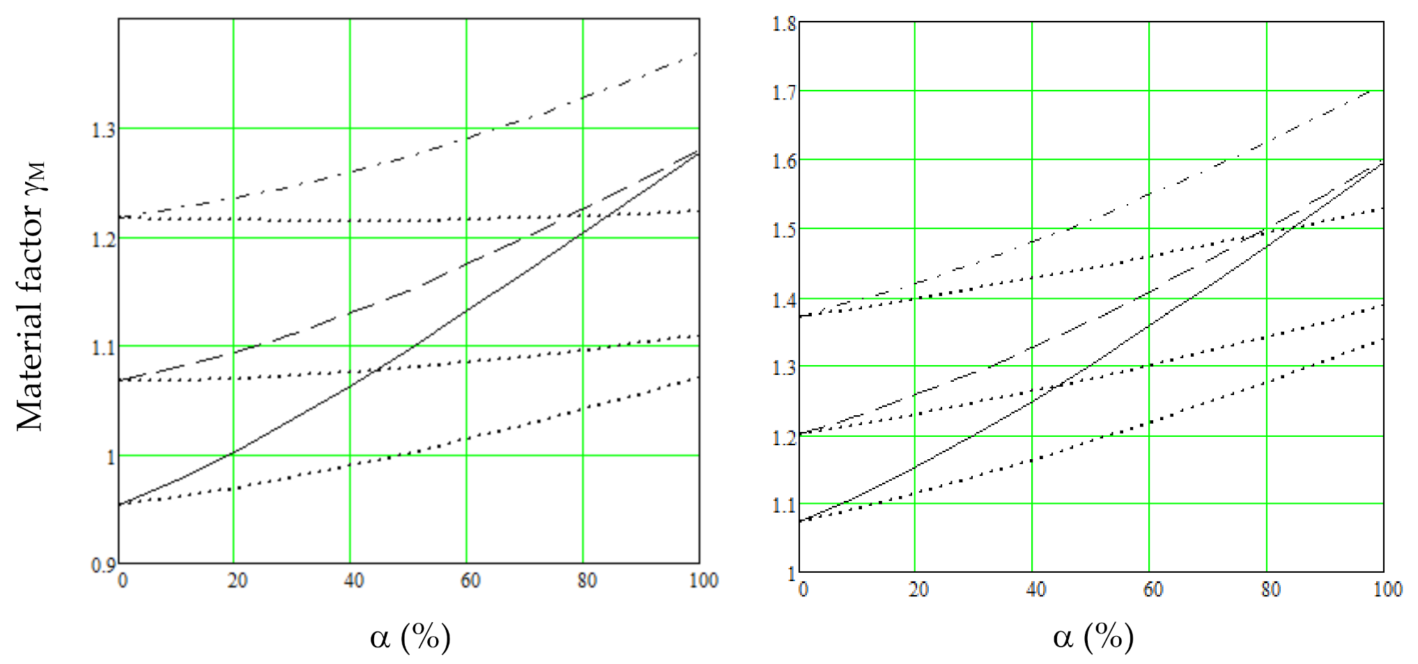
As per the material safety factors based on the Equations (8) and (9) and the assumptions explained above—β50 = 3.2, γL = γG = γQ = 1.2—the characteristic variable load is the same as the current load table value, i.e., the 50-year return load. This is illustrated in Figure 1, right. The solid line denotes steel, VM = 0.1, VQ = 0.4; the dashed line denotes timber, VM = 0.2, VQ = 0.4; and the dash-dotted line denotes concrete, VM = 0.3, VQ = 0.4. The dotted lines imply VQ = 0.2. Figure 1, left applies to an analogous calculation with γG = 1.35, γQ = 1.5.
We see that the lines are inclined upwards, and the assumptions mentioned above denote a poor outcome for the safety factors of the codes. As in the codes, the material safety factors are constant for each load proportion; thus, these curves should be horizontal or close to horizontal. The variable load safety factor γQ should be 20%–40% higher than assumed for loads VM = 0.4 and 10%–20% higher for loads VQ = 0.2. This deficiency is overcome by setting the characteristic load of the variable load as alternating in the manner explained in the next section.
3.2. Alternating Characteristic Load of the Variable Load
As explained above, timber (VM = 0.2) is selected here to be the primary material, which ideally matches with the reliability model, i.e., the material safety factor (γM) is the same for the permanent load and for the variable load, and this applies to both VQ = 0.2 and VQ = 0.4 loads.
The material safety factor for the permanent load calculated from Equation (8) is γM = 1.21, which is obtained by solving the equation
This safety factor is the same for the variable load, which is obtained when the characteristic load for VQ = 0.4 loads is increased by the factor = 1.32, obtained by solving the equation
Analogous equation for loads VQ = 0.2 results in the factor = 1.15.
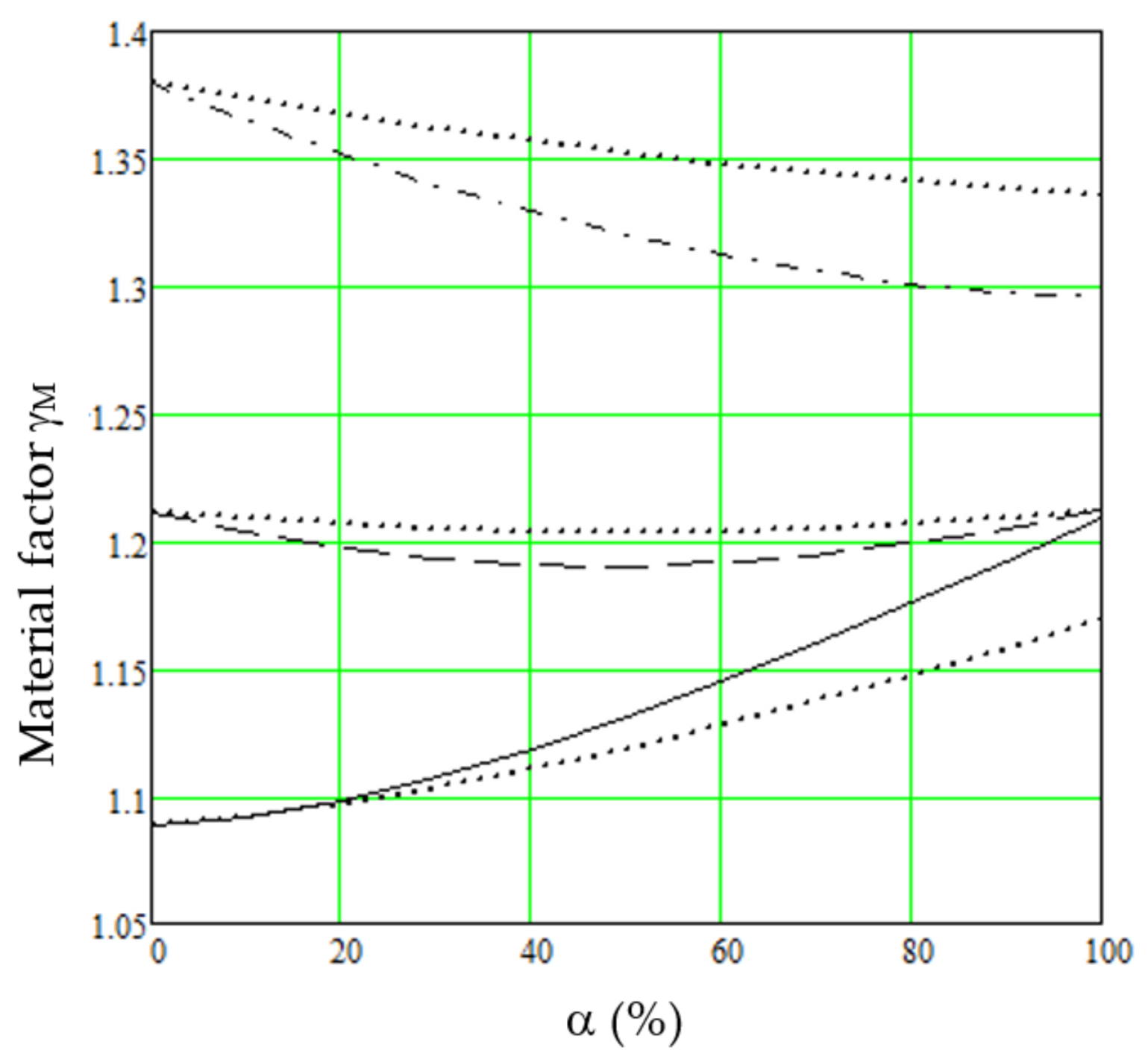
The material safety factors based on these assumptions are presented in Figure 2. The solid line denotes VM = 0.1, steel, VQ = 0.4; dashed line implies VM = 0.2, timber, VQ = 0.4; and dash-dotted line means VM = 0.3, concrete, VQ = 0.4. The adjacent dotted lines apply to VQ = 0.2.
Assuming that the safety factors are set with no unsafe design at the load ratios α = 20%–80%, the material safety factor for steel is γM = 1.18, which is applicable to VQ = 0.4 and α = 80%, whereas other load cases include excess safety of up to 7%. The safety factor for timber is γM = 1.21, which includes excess safety of up to 2%. The safety factor for concrete is denoted as γM = 1.37, which applies to VQ = 0.2 and α = 20%, whereas other load cases include excess safety of up to 5%. This code calibration is called the “constant concept”, as the material safety factors are constant in each material as they are constant in the current Eurocodes.
We see in Figure 2 that considerable savings are obtained when the characteristic load of the variable load is set to changeable. The total safety factor for loads VQ = 0.2 is 13% lower than for loads VQ = 0.4, which means about 7% material savings in all materials for loads VQ = 0.2. However, there is an insignificant disadvantage. In concrete, the loads VQ = 0.2 become critical and the material factor of concrete is γM = 1.37 instead of γM = 1.35.
The accuracy and the overall feasibility of this code calibration are good, but it can be enhanced further, as explained in the next section.
3.3. Alternating Material Safety Factors
Figure 2 illustrates that the accuracy for steel and concrete can be improved when the material safety factors are functions of the load proportion (α). There are two feasible options to achieve this: linear interpolation or the “linear concept”, and different safety factors for permanent load and variable load’s dominant loads, also known as the “variable concept”.
3.3.1. Linear Concept
When the material safety factor for steel is turned into a linear interpolation between α = 20%, γM = 1.10 and α = 80%, γM = 1.18, the reliability for loads VQ = 0.4 almost fully match with that of the target, but the loads VQ = 0.2 present up to 3% excess safety. Correspondingly, the safety factor for concrete is transformed through a linear interpolation between α = 20%, γM = 1.37 and α = 80%, γM = 1.34, and the reliability for loads VQ = 0.2 match with that of the target almost ideally, but the loads VQ = 0.4 present up to 3% excess safety. This safety factor setting results in a good overall reliability accuracy but harmful excess calculation work, as the material safety factors must be calculated for steel and concrete for each load case, and therefore, this concept is questionable in general codes. However, the code writer may allow this alternative as it is feasible in the computerized design.
3.3.2. Variable Concept
Steel structures are mainly loaded by variable loads, i.e., the load proportion is higher than 50%. On the other hand, in the concrete structures, the permanent load α ≤ 50% is normally dominant. Thus, we may set the primary material safety factors for the dominant cases and secondary factors for rare cases.
In this safety factor setting, the safety factor for steel in normal cases α > 50% is γM = 1.18, which presents excess safety of up to 5%. In rare cases, α ≤ 50% is γM = 1.13, which includes excess safety of up to 3%.
The safety factor for timber is always γM = 1.21, α = 20%–80%, which presents excess safety of up to 2%.
The safety factor for concrete in normal cases α ≤ 50% is γM = 1.37, which presents excess safety of up to 4%. In rare cases, α > 50% is γM = 1.35, which presents excess safety of up to 4%.
One option is that the steel load cases for α < 50% and concrete load cases for α > 50% are omitted as rare when this concept is simple in the actual design, i.e., the material safety factors for steel, timber and concrete are γM = 1.18, 1.21 and 1.37, respectively, which presents no unsafe reliability in load cases 20% < α < 80% and excess reliability error of 3%, 1% and 4%, respectively, assuming that steel load cases α ≤ 50% and concrete load case α > 50% are disregarded.
This option is worked out further in this article.
3.4. Rounding Errors
As explained above, it is feasible that the characteristic load of the variable load is set to changeable. The same applies to the material property.
The load factors are set above as γG = γQ = 1.2, i.e., they do not have rounding errors. If the codes are defined to include material safety factors, they include rounding errors.
In the current codes, the safety factors are normally rounded numbers with two decimals, and the last decimal is either 0 or 5. When the characteristic value of the material property is the 0.05 fractile, γG = γQ = 1.2 and the material safety factors for steel, timber and concrete are γM = 1.18, 1.21 and 1.37, respectively, the same outcome is obtained when the material safety factors are in unity, γM = 1, and the characteristic values are in fractiles 0.000476, 0.00456 and 0.00329, respectively. Such a setting simplifies the codes, lessens the design work and avoids the rounding errors in the material safety factors of about 2%. We may denote the fractiles using quantile indexes: βq, quantile = Φ(-βq), where Φ is the cumulative distribution function of the standardized normal distribution function, βq = 3.30, 2.61 and 2.72. If γG = γQ = 1, βq = 5.13, 3.53 and 3.34.
Though the safety factors are applied in the loads, it is feasible to remove the material safety factor as this way, the rounding errors are avoided.
4. Discussion
The proposed codes make an improvement regarding the current one in five points:
- The codes are simpler as the load factors are the same, γG = γQ = 1.2, and therefore there are less design errors.
- The codes result in less calculation work, less design output, and less design checking as the load factors are the same, and therefore, one structural analysis often is sufficient instead of the current two analyses in the SLS and in the ULS.
- The codes can be equally used in the partial factor design approach and in the design value approach, and the proposal enables the use of the simplest design codes, i.e., the allowable stress design method.
- The proposed codes result in material saving due to better reliability accuracy and due to less excess safety and less material in the cases of variable loads with low variation.
- The unsafe design cases are less, and therefore, failures are less.
A comparison is made approximately based on the mean cases, i.e., the load proportion α = 0.5 and the coefficient of variation of the variable load VQ = 0.3. The proposed load factors are γG = γQ = 1.2, and the material safety factors for steel, timber and concrete are γM = 1.18, 1.21 and 1.37, respectively. The mean characteristic load, i.e., load VQ = 0.3 is 23.5%, (15% + 32%)/2 higher than the current 50-year return load. Consequently, the safety factor for the variable load compared with the current one is γQ = 1.48 (1.2 ∗ 1.235), and the mean load factor, i.e., the load factor for 50% load proportion, is 1.34 (1.2 + 1.48)/2. Thus, the total mean safety factors for the basic materials are 1.58, 1.62 and 1.84, respectively.
The analogous mean load factor in the current Eurocodes, in the load combination (8.12), is 1.43 (1.35 + 1.5)/2 and the total mean total safety factors of the basic materials are 1.43, 1.86 and 2.15, respectively.
The proposed total safety factor for steel is 10% higher than in the current Eurocodes, which suggests that the safety factor for steel γM = 1.0 is not enough for β50 = 3.2 and should be increased by about 20% for this reliability. The questionable steel reliability was concluded by the author earlier [20]. In the calculation above, the uncertainty is omitted. If this factor is considered, the safety factor of steel should be increased even more.
4.1. Discussion on the Steel Reliability
The current safety factors of the Eurocodes are based on the independent load combination where a load reduction is applied. It is realized by calculating the variable load reliability for the 5-year load. The author explained earlier [13] that the variable load reliability should be calculated for the service time load, i.e., for the 50-year load, as this load strikes every structure. The current calculation is correct for the permanent loads, but the safety factors are too low for the variable loads. If the safety factors of the Eurocodes are calculated for the current target reliability index, β50 = 3.8, all safety factors should be increased, however, the increase in the steel safety factor is especially big.
The current material safety factors of steel, timber and concrete are γM = 1.0, 1.3 and 1.5, respectively. These factors should be in the variable load for β50 = 3.8 and γQ = 1.5, γM = 1.51, 1.55 and 1.72, respectively, i.e., 51%, 19% and 15% higher than the current values, respectively. In this article, the target reliability is set, β50 = 3.2, when the safety factors in the variable load γQ = 1.5 should be γM = 1.27, 1.28 and 1.37, respectively, i.e., the current safety factors for timber and concrete are enough for β50 = 3.2, but the safety factor of steel should be increased by 27%. If the safety factors are calculated independently, i.e., for the 5-year load and β50 = 3.8, the safety factors for the variable load should be γM = 1.28, 1.29 and 1.38, respectively, i.e., the current safety of steel should be increased by 28%.
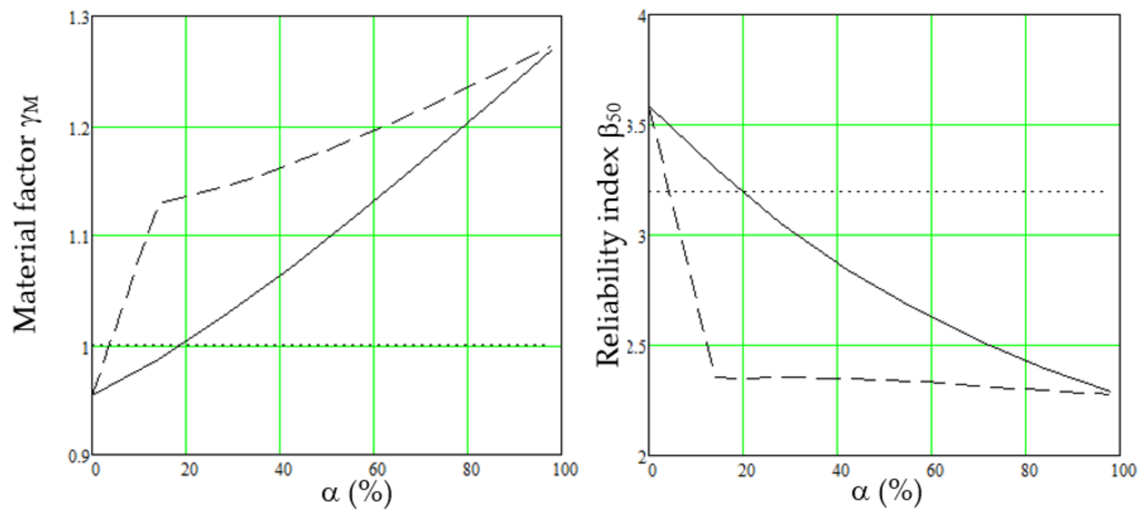
The safety factor and the reliability index of steel is illustrated in Figure 3, β50 = 3.2, γG = 1.15, 1.35, γQ = 1.5, as a function of load proportion (α).
The solid line in Figure 3 left denotes the material safety factor of steel calculated using the dependent combination rule (8.12) [1] (this line is the same as the solid line in left Figure 1), and the dashed line means the corresponding safety factor calculated using the independent combination rule (8.14,a,b) [1]. We also find in this calculation that the current safety factor for steel γM = 1.0 should be increased by about 20% when the variable load is dominating. The dotted line shows the current safety factor of steel, γM = 1.0.
The solid line in Figure 3 right denotes the reliability index calculated using the combination rule (8.12) [1], and the dashed line shows the corresponding reliability index calculated using the independent combination rule (8.14,a,b) [1]. The dotted line means the target reliability index β50 = 3.2. We see that the reliability index in the load combination (8.14,a,b) is about β50 = 2.3, α > 0.15, i.e., the failure probability is only Pf50 ≈ 1/100, and should be 15 times less for β50 = 3.2.
The apparent reason for the low material safety factor of steel γM = 1.0 is the current safety factor calculation, i.e., Equation (1), which wrongly estimates the safety factors that are seen in Figure 3. The dependent safety factors and reliability indexes at α = 0.15, 0.85 are γM.d = 0.99, 1.22; β50,d = 3.30, 2.40, i.e., a 23% increase in γM,d creates a 27% decrease in β50,d. The corresponding independent values are γM,i = 1.13, 1.24; β50,i = 2.36, 2.30, i.e., a 10% increase in γM,i creates a 3% decrease in β50,i. However, the same equation (Equation (1)) and the same scale are used for the dependent and the independent cases. Further, there are no limits for excessive deviation from the target.
The unsafe error of about 20% is big, and one may wonder why failures, for this reason, have not been reported in reality. There are at least two causes that mitigate the controversy:
- In the calculation above, the variable load distribution is assumed to be Gumbel. This distribution has a robust upper tail that makes the distribution excessively safe [21], which especially applies to steel.
- Steel failures normally are ductile, which allows the redistribution of stresses with decreased stress peaks.
4.2. Economic Evaluation
The proposed total safety factors for timber and concrete are 13% and 14% smaller, respectively, than in the current Eurocodes meaning savings in these materials.
The overall structural material used in Europe and set by the Eurocodes accounts for about EUR 150 billion (thousand million) (estimated by Forecon Oy, www.forecon.fi, accessed on 6 April 2020) and about EUR 100 billion is defined by the safety factors and the characteristic values. We assume here that this volume is equally divided into steel, timber and concrete. We may estimate further that when the safety factor decreases by 1%, structural material decreases by 0.5%. Thus, the decreased safety factors of concrete and timber 13% and 14%, respectively, result in the annual material savings of about EUR 4 billion in Europe.
As the load factors are the same, the structural analysis in the SLS and in the ULS often are the same, i.e., there is less calculation work, less design output and less checking. As the codes are simpler, there are fewer design errors. The proposed codes have negligible unsafe design cases regarding the target, and therefore, the structural failures are apparently less. Further, removing the rounding errors results in a theoretical saving of about EUR 1 billion.
Overall, we may estimate an annual saving of about EUR 5 billion in Europe.
The proposed codes make only one essential change to the present Eurocodes. The load tables of the variable loads should be changed. The safety factors should also be changed. Such changes are minor tasks in the amendment of the codes.
4.3. Environmental Impact
This study indicates that the volume of timber and concrete used in the construction work can be reduced by about 6% and 7%, respectively. On the other hand, the volume of steel should be increased. However, the reliability calculation of steel structures needs further studies. The overall economic impact obviously is positive. For example, 7% reduced use of concrete makes about 0.5% decrease in world CO2 emissions (https://en.wikipedia.org/wiki/Environmental_impact_of_concrete, accessed on 26 May 2021).
4.4. Unique Characteristics
The codes presented here have unique features. The primary characteristics are variable characteristic values and the partial safety factor codes which can be used in the allowable stress approach, too. Secondary features are variable material safety factors and avoiding the rounding errors. The author sets name on such codes “Poutanen’s model”.
5. Conclusions
- The target reliability index is set at β50 = 3.2 [7].
- The load factors are set as γG = γQ = 1.2.
- The characteristic values for the variable loads VQ = 0.4 are 1.32 times higher than the current ones, and for loads VQ = 0.2, they are 1.15 times higher. The current variable load table values should be multiplied by 1.15–1.32.
- The material safety factors are the same for all materials, γM = 1, and the characteristic values of the basic materials, steel, timber and concrete, are in quantiles βq = 3.30, 2.61 and 2.72, respectively, which means that the fictitious material safety factors are γM = 1.18, 1.21 and 1.37, respectively, and γG = γQ = 1.2.
- As the characteristic values are higher than the current ones, the fictitious load factors compared with the current Eurocodes are γQ = 1.38 for loads VQ = 0.2 and γQ = 1.58 for loads VQ = 0.4.
- According to this study, the current Eurocodes are about 13% and 14% over safe in timber and concrete designs for β50 = 3.2, respectively, and steel designs are about 10% unsafe.
- The proposed codes have the same load tables as the corresponding design value codes and can be used as the design value codes by setting the load factors at unity γG = γQ = 1 and by multiplying the material factors by 1.2.
- The proposed codes result in savings in structural material, especially in timber and concrete and savings in design work. The codes are simpler and result in fewer design errors, less design output and less design checking, the reliability accuracy is better, the unsafe design cases are negligible, and the environmental impact is improved.
Funding
The research received no external funding.
Institutional Review Board Statement
Not applicable.
Informed Consent Statement
Not applicable.
Data Availability Statement
Data is contained within the article. The data presented in the figures of this study can all be reproduced using the equations given in the study.
Conflicts of Interest
The author declares no conflict of interest.
References
- CEN. Draft prEN 1990:2020 Eurocode—Basis of Structural Design; CEN: Brussels, Belgium, 2020. [Google Scholar]
- CEN. EN 1992-1-1:2005, Eurocode 2. Design of Concrete Structures; CEN: Brussels, Belgium, 2005. [Google Scholar]
- CEN. EN 1993-1-1:2005, Eurocode 3. Design of Steel Structures; CEN: Brussels, Belgium, 2005. [Google Scholar]
- CEN. EN 1995-1-1:2004, Eurocode 5. Design of Timber Structures; CEN: Brussels, Belgium, 2004. [Google Scholar]
- International Organization for Standardization. ISO 8930 General Principles of Reliability of Structures; International Organization for Standardization: Geneva, Switzerland, 1987. [Google Scholar]
- International Organization for Standardization. ISO 2394, General Principles of Reliability of Structures, List of Equivalent Terms; International Organization for Standardization: Geneva, Switzerland, 2015. [Google Scholar]
- JCSS. Probabilistic Model Code, Parts 1 to 4, Basis of Design, Load and Resistance. Available online: https://www.jcss-lc.org/jcss-probabilistic-model-code/ (accessed on 20 January 2021).
- Gulvanessian, H.; Calgaro, J.-A.; Holicky, M. Designer’s Guide to EN 1990, EUROCODE: Basis of Structural Design; Thomas Telford Publishing: London, UK, 2002. [Google Scholar]
- JRC. Implementation of Eurocodes, Handbook 2, Reliability Backgrounds; JRC: Prague, Czech Republic, 2005; Available online: https://eurocodes.jrc.ec.europa.eu/showpublication.php?id=63 (accessed on 20 January 2021).
- Gulvanessian, H.; Holicky, M. Eurocodes: Using reliability analysis to combine action effects. Proc. Inst. Civ. Eng. Struct. Build. 2005, 158, 243–252. [Google Scholar] [CrossRef] [Green Version]
- Ranta-Maunus, A.; Fonselius, M.; Kurkela, J.; Toratti, T. Reliability Analysis of Timber Structures, VTT Research Notes 2109, Espoo. 2001. Available online: https://www.vtt.fi/inf/pdf/tiedotteet/2001/T2109.pdf (accessed on 26 March 2021).
- Joint Committee on Structural Safety. Reliability-Based Code Calibration. Available online: http://www.jcss.byg.dtu.dk/codecal (accessed on 20 January 2021).
- Poutanen, T.; Pursiainen, S.; Länsivaara, T. Combination of permanent and variable load is dependent. Appl. Sci. 2021, 11, 4434. [Google Scholar] [CrossRef]
- Köhler, J.; Sørensen, J.D.; Baravalle, M. Calibration of existing semi-probabilistic design codes. In Proceedings of the 13th International Conference on Application of Statics and Probability in Civil Engineering, ICASP13, Seoul, Korea, 26–30 May 2019. [Google Scholar]
- Köhler, J.; Baravalle, M. Risk-based decision making and the calibration of the structural design codes—prospects and challenges. Civ. Eng. Environ. Syst. 2019, 36, 55–72. [Google Scholar] [CrossRef]
- Baravalle, M.; Köhler, J. A risk-based approach for calibrating of design codes. Struct. Saf. 2019, 78, 63–75. [Google Scholar] [CrossRef]
- Nadolski, V.; Rózsás, Á.; Sýkora, M. Calibrating Partial Factors—Methodology, Input Data and Case Study of Steel Structures. Period. Polytech. Civ. Eng. 2019, 63, 222–242. [Google Scholar] [CrossRef]
- Poutanen, T.; Länsivaara, T.; Pursiainen, S.; Mäkinen, J.; Asp, O. Calculation of safety factors of the Eurocodes. Appl. Sci. 2021, 11, 208. [Google Scholar] [CrossRef]
- Poutanen, T. Uusi Rakenteiden Mitoitusmenetelmä (New method for structural design). Raken. Mek. 2011, 45, 201–212. Available online: http://rmseura.tkk.fi/rmlehti/2012/nro4/RakMek_45_4_2012_2.pdf (accessed on 20 January 2021).
- Poutanen, T.; Pursiainen, S.; Mäkinen, J.; Länsivaara, T. Combination of permanent and variable loads. Raken. Mek. 2018, 51, 1–9. Available online: https://rakenteidenmekaniikka.journal.fi/article/view/65175/35889 (accessed on 20 January 2021).
- Poutanen, T. Variable Load Distribution. Second International Conference on Vulnerability and Risk Analysis and Management (ICVRAM) and the Sixth International Symposium on Uncertainty, Modeling, and Analysis (ISUMA), Liverpool, UK. 2014. Available online: https://ascelibrary.org/doi/abs/10.1061/9780784413609.100 (accessed on 6 April 2021).
Figure 1.
Material safety factors (γM) as the function of load ratio (α). Left; γG = 1.35, γQ = 1.5, right γL = γG = γQ = 1.2. Solid lines denote VM = 0.1, VQ = 0.4; steel; dashed lines imply VM = 0.2, VQ = 0.4, timber; and dash-dotted lines represent VM = 0.3, VQ = 0.4, concrete. Dotted lines apply correspondingly to VQ = 0.2.

Figure 2.
Material safety factors (γM) as the function of load ratio (α) for the updated characteristic values. The solid line denotes VM = 0.1, steel, VQ= 0.4; dashed line implies VM = 0.2, timber, VQ = 0.4; and dash-dotted lines represent VM = 0.3, concrete, VQ = 0.4. The dotted lines apply to VM = 0.2.

Figure 3.
The left figure shows the material safety factors (γM) of steel, solid line calculated using the dependent combination rule (8.12) and dashed line calculated using the independent combination rule (8.14a,b). The right figure discloses the corresponding reliability indexes. The dotted lines denote the material safety factor of steel, γM = 1.0 and the target reliability β50 = 3.2.


Table 1.
The three examined materials steel, timber and concrete with parameters: VM = coefficient of variation; μM = mean; σM = deviation; γM = material safety factor.
Table 1.
The three examined materials steel, timber and concrete with parameters: VM = coefficient of variation; μM = mean; σM = deviation; γM = material safety factor.
| Material | VM | μM | σM | γM |
|---|---|---|---|---|
| Steel | 0.1 | 1.1841 | 0.1184 | 1.0 |
| Timber | 0.2 | 1.4125 | 0.2825 | 1.3 |
| Concrete | 0.3 | 1.6921 | 0.5076 | 1.5 |
Publisher’s Note: MDPI stays neutral with regard to jurisdictional claims in published maps and institutional affiliations. |
© 2021 by the author. Licensee MDPI, Basel, Switzerland. This article is an open access article distributed under the terms and conditions of the Creative Commons Attribution (CC BY) license (https://creativecommons.org/licenses/by/4.0/).
Share and Cite
MDPI and ACS Style
Poutanen, T. Code Calibration of the Eurocodes. Appl. Sci. 2021, 11, 5474. https://doi.org/10.3390/app11125474
AMA Style
Poutanen T. Code Calibration of the Eurocodes. Applied Sciences. 2021; 11(12):5474. https://doi.org/10.3390/app11125474
Chicago/Turabian StylePoutanen, Tuomo. 2021. "Code Calibration of the Eurocodes" Applied Sciences 11, no. 12: 5474. https://doi.org/10.3390/app11125474
Note that from the first issue of 2016, this journal uses article numbers instead of page numbers. See further details here.