Article

Virtual Marker Technique to Enhance User Interactions in a Marker-Based AR System

Graduate School of Information, Production and Systems, Waseda University, 2-7 Hibikino, Wakamatsu Ward, Kitakyushu, Fukuoka 808-0135, Japan
*
Authors to whom correspondence should be addressed.
Appl. Sci. 2021, 11(10), 4379; https://doi.org/10.3390/app11104379
Submission received: 19 April 2021 / Revised: 2 May 2021 / Accepted: 7 May 2021 / Published: 12 May 2021
(This article belongs to the Collection Virtual and Augmented Reality Systems)

Abstract

:
In marker-based augmented reality (AR) systems, markers are usually relatively independent and predefined by the system creator in advance. Users can only use these predefined markers to complete the construction of certain specified content. Such systems usually lack flexibility and cannot allow users to create content freely. In this paper, we propose a virtual marker technique to build a marker-based AR system framework, where multiple AR markers including virtual and physical markers work together. Information from multiple markers can be merged, and virtual markers are used to provide user-defined information. We conducted a pilot study to understand the multi-marker cooperation framework based on virtual markers. The pilot study shows that the virtual marker technique will not significantly increase the user’s time and operational burdens, while actively improving the user’s cognitive experience.

1. Introduction

The evolution of augmented reality (AR) technology has created different types of AR for various purposes [1]. AR can be combined with other new technologies, thus it has been widely used in various fields such as education [2,3,4], medicine [5,6,7], robotics [8,9,10], and manufacturing [11,12]. Previous research has investigated the state of the art technology in this area by reviewing some recent applications of AR technology as well as some known limitations regarding human factors in the use of AR systems [13,14,15]. Some studies have mentioned some technical challenges faced in future AR applications—for example, binocular (stereo) view, high resolution, colour depth, luminance, contrast, field of view (FOV), and focus depth [16,17,18].
Aside from the technical challenges, the user interface must also follow some guidelines [19]. Interaction is an important aspect that has been widely discussed [18,20]. Early AR interfaces used input techniques inspired from desktop interfaces or virtual reality, but over time more innovative methods have been used, such as tangible AR [21,22] and natural gesture interaction [23,24]. ser issues encompass such things as ease of use, whether the hardware necessary for AR will reach an acceptable design that people will want to wear and use, and whether the technology will be accepted as part of daily life [25]. For example, if the cost of using an AR system is too high, this may affect the social acceptance of the system. Therefore, one of the most important aspects of AR is to create appropriate techniques for intuitive interaction between the user and the virtual content of AR applications [19].
There are three different types of AR, which are marker-based AR, markerless AR, and location-based AR [26,27,28]. Marker-based AR is used when what the user is looking at is known [29]. It has been proven to be sufficiently robust and accurate, and so far almost all AR software development kits support marker-based tracking methods [30]. Marker-based AR gives the position of the marker in the camera coordinate system [31]. Therefore, the sequence of markers can be determined by obtaining the coordinate information of multiple markers. Coordinate information can be used to combine multiple markers to complete some control functions [32]. In fact, although many AR sdks support the simultaneous recognition of multiple markers, there have been few in-depth studies on the cooperation of multiple markers [33]. In the work of Tada et al. [34], the authors implemented a prototype system which was capable of drawing and moving shapes with multiple physical markers and created loops and branch executions. It was possible to edit the program by writing on the paper cards. Users can carry out some creative activities and perform simple operations on 2D images. Although the research attempts to establish the connection of multiple markers, the use of multiple markers is mainly intended to provide learners with simple and intuitive basic programming learning. More often, multiple AR markers are just used for more accurate detection and tracking [35,36,37]. The question of how to use multiple markers to build an AR system framework is our main research purpose.
There are some problems in marker-based AR systems. In marker-based AR systems, markers are usually relatively independent. Moreover, the markers are predefined by the system creator in advance, and users can only use these predefined markers to complete the construction of certain specified content [38]. Therefore, such systems usually lack flexibility and do not allow users to create content freely.
In our research, we propose a virtual marker technique to build a marker-based AR system framework where multiple AR markers, including virtual and physical markers, work together. Virtual markers are generated from physical template markers or existing virtual markers. Virtual markers mainly consist of function markers, variable markers, and number markers. Users can completely customize these markers and use them. Therefore, such a framework has the scalability to complete more complex functions. In addition, the virtual marker technique can be used to manipulate AR objects more conveniently, which enhances the interactivity and scalability of the marker-based AR system. We divide the cooperation of multiple markers into two categories—one is an ordered series of markers, such as that used in tangible programming, and the other is an unordered series of markers. We have designed a set of gestures for virtual marker operations so that they can be used in the same way as physical markers. Multiple markers can be used as control commands as well as inputs and outputs. We have implemented a prototype system to illustrate our framework. The system includes multiple markers, a webcam, a leap motion, and software. The user can arrange multiple markers in a specific order to create a program or connect markers through hand gestures, then the result will be presented in the form of AR. We conducted a pilot study on the marker-based system that introduced the virtual marker technique to understand its potential value in an AR system.
Our work provides the following contributions:
(1) A virtual marker technique that can be used to expand the marker-based AR system;
(2) A framework that combines multiple markers, where markers can provide functions such as control, input, and output.
The remainder of this paper is organized as follows. Section 2 describes related work. Section 3 and Section 4 describe the virtual marker technique and how it can be used in marker-based AR systems. In Section 5, we describe the implementation of the system. Section 6 describes our pilot study and the results. Section 7 discusses the advantages of the system framework and the parts to be improved. In Section 8, we summarize our research and future plan.

2. Related Work

In this section, we review related work on multiple marker cooperation, marker-based AR systems, and hand gesture recognition.

2.1. Multiple Marker Cooperation

Hattori et al. [39] proposed a programming tool using tangible blocks and AR. Using AR, it was possible to create intuitive programming that could interact with reality. Jin et al. [40] presented a novel tangible programming tool using AR technology for young children. Using this system, children could create their own programs by arranging programming blocks and debug or execute the code with a mobile device. The work of Sing et al. [35] involved the design and development of multimedia and multi-marker detection techniques in an interactive AR colouring book application for aquarium museum. It allowed users to express, create, and interact with their creativity through coloring activities. Boonbrahm et al. [36] developed a technique for generating a stable large 3D model for remote design collaboration using multiple markers. By assigning each side of a cube one marker to replace a single 2D marker, the accuracy of tracking was improved. Zeng et al. [37] developed an AR application aiming to activate the interests of user and improve the experience of learning to play the piano. The virtual keys can be accurately superimposed on piano keys using multi-marker tracking.
Their work provides possibilities to combine the information of multiple markers together. In our research, we will use multiple markers as a controller or container for information transmission. In the above-mentioned research, all the markers used were physical markers. In this research, we will propose a system based on virtual and physical markers.

2.2. Marker-Based AR System

Gherghina et al. [41] proposed a marker-based tracking system that detects QR-codes from a camera capture and overlays rich media obtained from a server. Andrea et al. [42] implemented a tracking marker-based method in textbooks and developed an AR-based geometry research application. The application helps students learn shape and geometry formulas from data analysis tests on student learning improvement. The study of Ambarwulan et al. [43] focused on the technique of instructional media that is integrated with AR to increase students’ interest in their studies. They emphasized the techniques of designing learning media in the form of AR applications for use on smartphones. Norraji et al. [44] discussed a type of mixed-reality book experience that augments a colouring book with user-manipulated three-dimensional contents in a mobile-based environment. Bouaziz et al. [45] proposed a learning system based on AR that overlays digital objects on top of physical cards and renders them as a 3D object on mobile devices to help with teaching food skills using related phrases and sounds. Pashine et al. [46] described how marker-based AR applications can be used for both uploading and retrieving notices and how markers processed as images while visualized as 3D objects. Akussah et al. [47] developed a marker-based handheld AR application for learning geometry with a focus on the individual’s experience, then expanded it into a collaborative AR game which addresses other mathematical learning outcomes.

2.3. Gesture Interaction for AR Applications

Lee et al. [48] developed a 3D vision-based natural hand interaction method. One of the steps is simple collision detection based on short-finger rays, which is used for interaction between the user’s finger and the AR object. Yang et al. [24] incorporated AR and CV algorithms into a Virtual English Classroom to promote immersive and interactive language learning. By wearing a pair of mobile computing glasses, users can interact with virtual contents in a three-dimensional space using intuitive free-hand gestures. Bellarbi et al. [49] presented a hand gesture recognition method based on color marker detection. The user can perform different gestures, such as zooming, moving, drawing, and writing, on a virtual keyboard. Bai et al. [50] presented a prototype for exploring natural gesture interaction with handheld AR applications using visual tracking-based AR and freehand gesture-based interaction detected by a depth camera. The 3D gesture input methods were found to be slower, but the majority of the participants preferred them and gave them higher usability ratings. Lee et al. [51] presented a vision-based framework to manipulate AR objects robustly in a markerless AR system. From their experiments, they found that the proposed hand mouse could manipulate objects in a feasible fashion. Vasudevan et al. [52] designed a system where remote files and directories are augmented in real time over the camera’s view of the smartphone, tablet, or PC. It provides interaction between the user and the digital space using only hand gestures, without the use of any special purpose devices.

3. Virtual Marker Technique

In this chapter, we will introduce the virtual marker and its generation and operation.

3.1. Why Virtual Markers

In marker-based AR systems, markers are usually relatively independent. Moreover, markers are predefined by the system creator in advance, and users can only use these predefined markers to complete the construction of certain specified content. Therefore, such systems usually lack flexibility and do not allow users to create freely. However, unless the operation performed by the user is predictable, it is often difficult to accurately provide a large number of physical markers. Therefore, we propose a virtual marker technique to solve these problems. Virtual markers provide two main advantages. The first advantage is that they allow users to use simple template markers to customize content, including function names, variable names, and numbers. This can solve the inconvenience of providing users with a large number of physical markers. The second advantage is that virtual markers can be used to store combined information. That is, the content of the virtual marker can be changed in real time. Users can continuously process and merge content to achieve more complex functions.

3.2. Virtual Marker

A virtual marker is a marker that does not exist in the real world but that can be seen in an AR scene. It can work exactly the same as a physical marker. In an AR scene, physical markers and virtual markers can work together. When the system is running, the information from the physical markers and the virtual markers will be read to compose complex information or instructions.
Virtual markers have a similar appearance to physical markers but have user-defined information marked in red (see Figure 1). They can be used with physical markers naturally. The virtual marker connects the real world and virtual world in the system. It is a virtual object generated by physical markers but it can work with the physical marker, which means that it can interact with the real world. It can also interact with the virtual world—for example, as a finger ray from a virtual hand. Therefore, a virtual marker represents the alignment of the virtual world and real world.

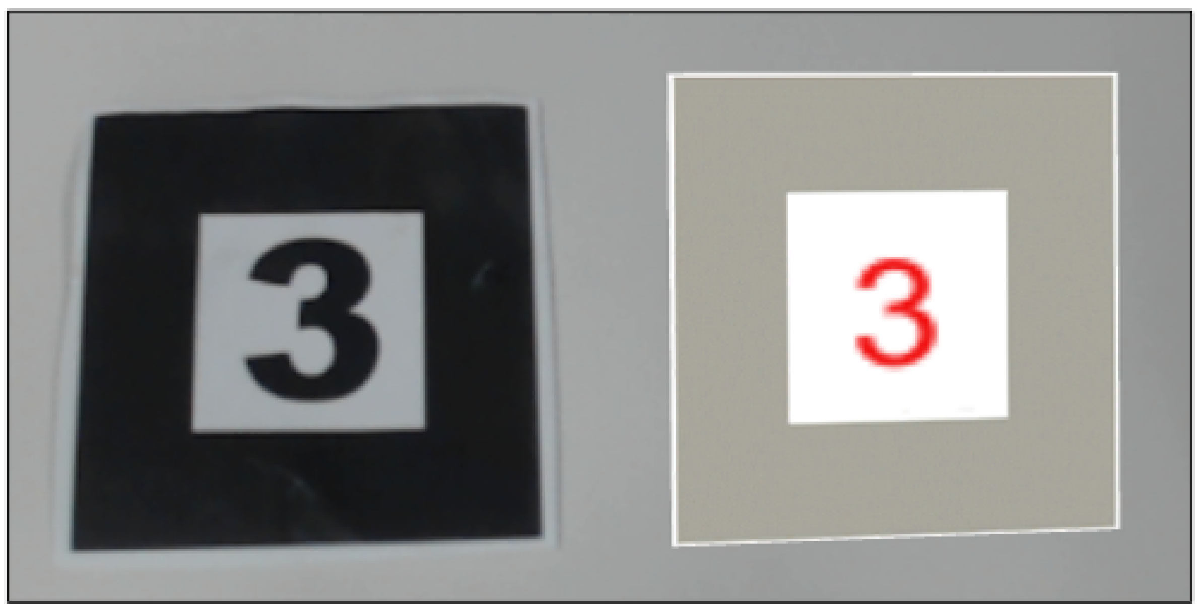
3.3. Basic Virtual Marker Generation

Virtual markers mainly consist of function markers, variable markers, and number markers. We provide two input markers, a number input marker and a keyboard input marker (see Figure 2).
The number virtual marker is generated by a physical constant marker and a number input marker (see Figure 3).
The function virtual marker is generated by a physical function marker and a keyboard input marker. The variable marker is generated by a physical variable marker and a keyboard input marker. The system will provide corresponding template to generate virtual markers based on the recognized markers. The information entered by the user will be recorded by the system and combined with a virtual marker template to generate a specific virtual marker. Virtual markers will be generated at the locations of physical markers (constant, function, and variable markers). After being generated, the user can freely move the virtual marker and continue to generate new virtual markers.

3.4. Combined Marker Generation

The virtual markers can be combined to generate a new virtual marker that carries combined information. The user arranges the physical marker and the virtual markers in order and uses gestures to complete the creation of the combined virtual marker. The system will determine the content of the combined virtual marker according to the marker sequence and the number as well as the category of the virtual markers.
The user can place a physical marker named set, a variable virtual marker, and a number virtual marker in sequence. After the user performs the defining gesture, the system will generate a new virtual marker containing the corresponding variables and number information at the position of the physical marker (see Figure 4). The user can also place a physical marker named 3D and three number virtual markers in sequence to generate a 3D vector marker. After the combined virtual marker is generated, the system will not automatically clear the original virtual markers, meaning that users can continue to use these markers to create new combined virtual markers. These combined virtual markers can be easily used to control AR objects in our system.

3.5. Manipulating Virtual Marker

Virtual markers are essentially virtual objects. The user can interact with physical markers by grabbing and moving. Similarly, users can use hand gestures to manipulate and interact with markers in our system. In the current design, we use right-hand gestures.
There are some descriptions of these hand gestures (see Figure 5):
(a) Defining gesture: This gesture is a thumb-up gesture which will tell the system to define the current command and execute it.
(b) Selecting gesture: The user needs to spread his thumb finger and index finger. The index finger will emit finger rays for selection in the AR scene. The user can use the finger ray to select virtual markers for manipulation. In order to express the selected state of the virtual marker, the system will highlight the selected virtual markers in red.
(c) Deselecting gesture: When the user makes a clenched fist, the state of the selected marker at this time will be restored to the unselected state.
(d) Dragging gesture: The dragging gesture needs to gather all fingers in one point. Using this gesture, the user can drag and change the position of the virtual markers in the selected state. The user can use this gesture to arrange virtual markers.
(e) Copy gesture: The user stretches their index finger, middle finger, and thumb while tightening the other two fingers. The user can use this gesture to copy the selected virtual markers. After the copy is complete, the virtual markers will be restored to the unselected state.
(f) Parameter/value change gesture: If the index finger and middle finger are extended and the other fingers are retracted, accompanied by a certain rightward movement speed, this is regarded as an increase in the number or parameter. Each time the user swipes to the right, the parameter value will increase by one. If the index finger and middle finger are extended and the other fingers are retracted while moving to the left at a certain speed, this is considered as a decrease in the number or parameter. Each time the user swipes to the left, the parameter value will decrease by one.
(g) Deleting gesture: To make this gesture, the user needs to open all their fingers and hand palm and move their hand left and right with some speed. With this gesture, the user can delete the selected virtual markers in the scenery.
It is worth noting that different users may be accustomed to different gestures. In fact, we are more concerned with what kind of interaction users can perform using hand gestures.

4. Virtual Marker Technique in Marker-Based AR System

This section introduces the virtual marker technique in a marker-based AR system.

4.1. Level 1: Virtual Marker Programming

In our system, virtual markers can be used in conjunction with marker-based tangible programming to provide scalability and customization. We named this virtual marker programming. Markers and hand gestures will be used in virtual marker programming. Each marker contains information, and multiple markers will be placed in the scene in a specific order. The arrangement will be read and recognized by the system and a visualization program will be generated. Since it is difficult to accurately identify a large number of markers at the same time in a limited FOV, we propose an information combination method. Information from multiple markers will be merged and become the content of the first marker. After that, the user can use a single marker to replace the previous multiple markers to make more complex programming. In the AR scene, virtual and physical markers can be observed at the same time. These markers will be located in the same coordinate system. Therefore, the system can obtain a marker sequence composed of virtual and physical markers. Language syntax structures are provided for virtual marker programming, such as condition structure and loop structure. The architecture of the system can be expanded on this basis and more structures can be introduced.
We use an example to illustrate how gestures and virtual markers are used (see Figure 6). By using a defining gesture, the user can merge the content of multiple markers into the first marker. The user can copy the marker using selecting and copy gestures. When the marker is selected and the user performs a value change gesture, the value of the selected marker will be modified. In this example, we show how the information of the virtual markers can be combined.
Based on this example, users can complete more complex virtual marker programming (see Figure 7). The user can merge the combined information into the first marker using a defining gesture. The final function definition can be formed through multiple markers that already contain combined information.

4.2. Level 2: AR Objects Control

In our framework, we show several examples to illustrate how users can control AR objects through virtual markers containing combined information (including movement, rotation and action).

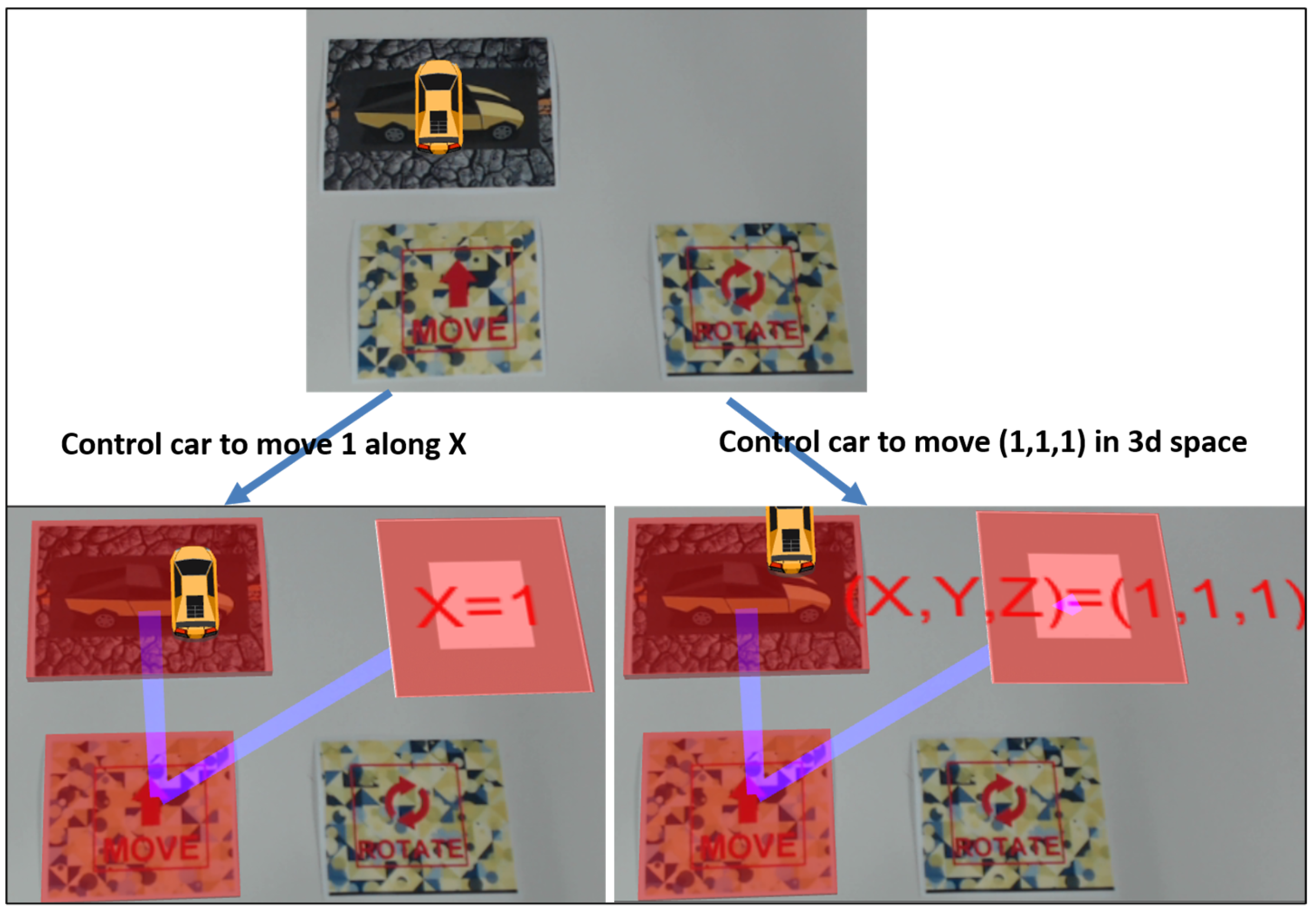
4.2.1. Movement and Rotation Control

In our system, we illustrate an example of applying multiple markers to control the movement and rotation of a car.
A virtual car will be displayed on top of the car marker. The car marker can receive multiple types of control markers as parameters, such as moving markers and rotation markers (see Figure 8).
After the user connects the car marker with the moving marker or the rotation marker with a selecting gesture, the user can move and rotate the car by touching the text block on the moving or rotation marker. This is an example of using multiple physical markers for control in a typical marker-based AR system.
However, the control of AR objects based on markers usually cannot accept parameters from users. With the help of virtual markers, users can use custom data information as an input in the system to accurately control the movement and rotation of the car. The user can select multiple markers to be connected through hand gestures. When markers are selected, the markers will be highlighted in red. A moving or rotation marker can accept the combined virtual marker as an input parameter. The virtual marker (X = 1) is generated by a variable virtual marker (X) and a virtual number marker (1). It can be used to control the movement or rotation of the car in the X-axis. The 3D vector virtual marker can be used to adjust the direction or angle of the car in 3D space.

4.2.2. Avatar Action and Scale Control

In the AR system, the avatar is usually a 3D model. The size of the model is preset when the system is built. Users usually control continuous changes in the size of the model through a button, but they cannot precisely control such changes. The 3D vector virtual marker can provide this accurate size change so that the user can change the size of the model precisely. Users can generate 3D vector markers with different values through customization, then freely control the size of the avatar (see Figure 9).
In addition, we provide a control method for the avatar in the system. The control marker can be accepted as a parameter of the avatar marker. The user can click the text block on the control marker to control various actions of the avatar.

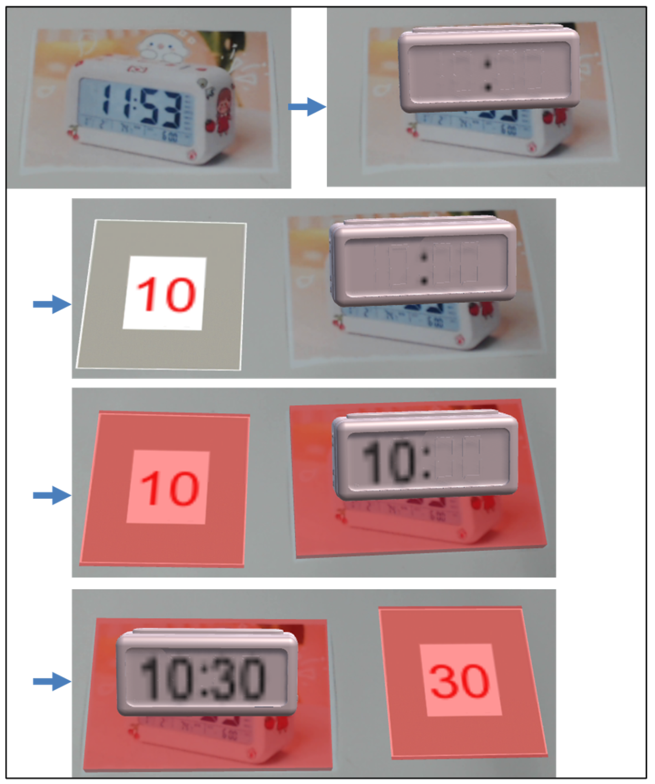
4.2.3. Virtual Timer Control

Another example is the use of virtual markers to set a virtual timer. A virtual timer marker is provided and a virtual timer is displayed on the marker. In the initial state, the virtual timer does not contain time information. Users can use virtual markers to customize the start time of the virtual timer. After the user selects the two-digit number marker and the virtual timer marker, the two-digit number marker can be used as a parameter of the virtual timer marker to set the left parameter of the AR virtual timer. The right parameter is also set in the same way (see Figure 10). The virtual timer will start to count automatically after setting. In the system, we also provide a control marker for the virtual timer. The user can control the pause, continue, and reset of the virtual timer through the control marker.

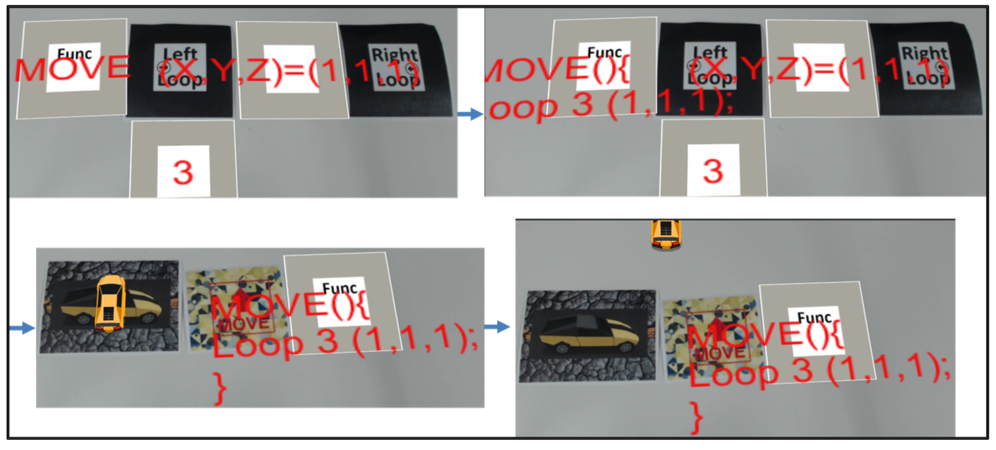
4.3. Level 3: Combination of Level 1 and 2

In addition to providing users with a basic function definition, virtual marker programming can also be used in the programming control of AR objects. Our system implements two examples to illustrate how to combine virtual marker programming and AR object control together.
The first example is to control the movement of the car by programming, including 2D plane movement and 3D space movement. As shown in the figure, the user can arrange multiple markers in a certain order. The system will read the order according to the depth-first mode. In Figure 11, the sequence is the function marker, the left loop marker, the number 3 marker, the 3D vector marker, and the right loop marker. The defined function is that the object moves with the 3D vector of (1, 1, 1) as a parameter and repeats this movement process 3 times. Then, the user places the car marker, the moving marker, and the defined function virtual marker in order. When the marker sequence is correctly read, the user can use a defining gesture to tell the system to execute the program. After that, the car will move according to the defined function. This program has other variants. For example, users can use a rotation marker instead of a moving marker to define the rotation. Users can also use other virtual number markers to change the loop times. Markers containing variable and number information can also be used to replace 3D vector markers for movement in a 2D plane. In addition, users can freely add more combined markers to expand the program.
The second example is controlling the avatar’s action sequence and the time of each action through programming. Similarly, the user can arrange multiple markers in a certain order and the system will read the program accordingly. The sequence is the function marker, run marker, number 1 marker, idle marker, and number 4 marker. The defined process is that the object will run for 1 second and then perform casual action for 4 seconds. Then, the user places the avatar marker and the function marker in order. The user can use a defining gesture to execute the program. After that, the avatar will perform actions one by one, and each action will be executed at a user-defined time (see Figure 12). Users can also freely add action markers or loops to define more complex AR controls. For example, the user can add the loop marker and the number of loops as in the first example to control the repetition of the avatar’s action sequence. The user can also add multiple action markers and change the time for each action to change the avatar’s action.
The above two examples show how to combine virtual and physical markers to program the control of AR objects in our system. In fact, the combination of level 1 and level 2 can accomplish more control functions than the above two examples. For example, users can also define control structures under different conditions or use other structures to program the AR objects. Since the main variable information in programming is dynamically created by the user and other structural information is provided by the physical markers, such a system is extensible.

5. System Implementation

The development operation system is Windows 10 Home 64-bit, with 8 GB RAM on the ThinkPad manufactured for lenovo. The main software we used is Unity 3D Engine 2018.4.19f1 (64-bit), which provides support for AR system development. We mainly used C# programming language as a scripting language to implement the system. In order to identify the marker, we used the Vuforia engine. To use leap motion in our system, we need Leap Motion Orion 4.0.0 and the Leap Motion Core Asset Package as software support. For gesture recognition, we used SVM for classification. In our system, we use Accord.NET API to help us recognize user gestures.

5.1. Multiple Marker Process

There are two types of processing in the system: one is a sequence of markers that rely on order, and the other is disordered multiple markers.
The marker sequence represents the logic of the visualization program. Therefore, we need to identify markers with a defined sequence. In the first step, we need to identify all the markers in the scene and access their coordinate positions in the Unity scene. Next, we will use their coordinates to obtain the sequence we defined. In this step, since we cannot accurately place the two markers on the same x-coordinate or y-coordinate, we need to set a threshold for the coordinate position to determine whether the two markers are in the same row or in the same column. After that, we will obtain a marker sequence for processing.
For disordered multiple markers, the system will first identify multiple markers. The system will establish a connection based on the markers selected by the user as input information. After establishing the connection between markers, the user can complete AR object operations by operating the markers.

5.2. Virtual Marker

Virtual marker modeling
We provide templates for virtual markers. Different template markers will be used when different types of virtual markers are generated. The template markers contain two child components—one is the highlighted component and the other is the text component. The highlighted component will be displayed when the marker is selected to inform the user of the current status. The text component accepts user input and displays it. The prepared templates are saved in a prefab folder for later use.
Generating virtual marker
In the AR scenario, the status of the physical markers will be checked. When it detects that the physical markers meets a certain requirement, the system will track and record the coordinate information of the physical marker. After the system detects user input and receives the confirmed instructions, the system will dynamically generate a virtual marker according to the position of the template marker and record this virtual marker. After that, the user can perform operations on the virtual marker or continue to generate new virtual markers. For the virtual marker containing combined information, we use a blank virtual marker template. The combined information will be processed according to the user’s operation and presented in the text.
Manipulations of virtual marker
The user needs to first determine the virtual markers to be operated. A pointing gesture needs to be performed to determine the virtual markers. Combining the selected virtual markers with the user’s real-time gesture information, the user can realize the manipulation of the virtual markers.
AR system with virtual markers
According to the position information of all the markers including the physical and virtual markers in the AR scene, we can obtain the marker sequence from Unity. Markers serve as information carriers, and their position information is used to determine the order of information combination in level 1. Therefore, the system can complete programming that combines virtual and physical markers.
In fact, the system will read all the markers in the AR scene but will not automatically establish a link between the markers. In level 2, the user selects markers and the system then establishes a connection between these markers. In level 2, the user can place the markers at any position without considering the marker sequence. This is object-oriented programming, so it has the potential to replace any component.
The processing mode of level 3 is the same as that of level 1. The user does not need to connect the markers but arrange the markers in order. The system will process the programs according to the marker sequence.
All three levels are integrated, and the system will judge the input and output based on the markers and the user’s operation.

5.3. Hand Gesture

In our system, we use leap motion as a depth sensor to track the user’s hand data. Leap motion can track the position data of fingers, palms, and wrists in each frame. We can access this data and use it for gesture recognition. In order to recognize the user’s gestures, we first need to classify the user’s hand shape. Next, we need to access some gesture data. Combining hand shape and gesture data, we can determine the user’s gesture.

6. Pilot Study

This chapter describes a pilot study using our proposed system. In the following sections, an outline of the experiment and detailed information on the experimenters, experiment procedures, and results are described in this order.

6.1. Experiment Outline

Experimenters were asked to perform 2 tasks to experience the proposed system (see Figure 13). In the first task, they were asked to complete a designated virtual marker programming task after receiving training. The task completion time was recorded and a questionnaire survey was conducted after task 1. In the second task, they were asked to use multiple markers on their own to experience the control of AR objects. After that, we interviewed them to ask their impressions of and suggestion for the system. The purpose of the experiment was to measure the ease of use and user experience of the proposed system.

6.2. Study Hypothesis

In our usability research, there are two main issues that need to be understood. In traditional marker-based systems, markers are usually physical markers. Users are accustomed to using physical markers to build AR systems. Therefore, due to the difference in usage characteristics, after the introduction of a virtual marker technique, it is necessary to better understand the user’s usage and cognitive experience. Considering the certain level of system cognition required to operate the system, we put forward the our first study hypothesis regarding usage experience.
Hypothesis 1 (H1).
Although the virtual marker technique will lead to changes in user usage, it will not be a significant time and operational burden to users.
Regarding cognitive experience, we propose two experimental hypotheses.
Hypothesis 2 (H2).
The use of virtual and physical markers to establish the AR system will not reduce the user’s understanding of the system and may positively increase the user’s interest in using the system.
Hypothesis 3 (H3).
The virtual marker technique can effectively expand the functions of the system and have a positive impact on users’ cognitive experience.

6.3. Participants

Five student volunteers (M = 23) participated in the pilot study. They all have a certain background in computer science. Three volunteers have more than two years of programming experience and two have between six months and two years of experience. Four volunteers have knowledge of the marker-based system. None has ever tried to program through a marker-based system.

6.4. Condition and Procedure

Before starting the experiment, we first explained the research purpose and experimental method to the experimenters. Next, we introduced the basic specifications of virtual marker programming, such as how to use template markers and syntax, the meaning of each marker, how to use gestures, and what kind of programs can be built. After that, the experimenters were provided with several training examples before the experiment to understand virtual marker programming. The content of examples is as follows. In these examples, the experimenters were provided with markers required for the answer in advance. We observed their operations and provided them with guidance.
Training example 1: A program that creates a virtual function marker, a virtual variable marker, and a virtual number marker.
Training example 2: A program that combines virtual and physical markers to define the first marker (If X = 1).
Training example 3: A program that defines the Fibonacci function.

6.5. Task 1

After completing the examples, they were given the first task. The experimenters were provided with the physical markers needed for the experiment and our proposed system. They were provided with C# code on the factorial function to help them build the program (see Figure 14). The content of the task was displayed on the external screen, and the experimenters could browse the content of the task freely. The part of the source code that needed to use the virtual markers was marked in red, and the black part was carried or generated by the physical markers. On the PC screen, the experimenters could perform real-time operations to complete the corresponding experimental task. The system provided log information to help them use the system.
Task 1: A program that defines the Factorial function.
Defining the Factorial function covers several main steps, including how to create virtual markers, how to combine information, and how to use gestures. At this point, they needed to select the desired markers from all the markers and create their own program independently. The experimenters’ experimental data (i.e., complete time) were recorded. After completing task 1, the experimenters took a questionnaire survey.

6.6. Task 2

The experimenters were introduced in how to create virtual markers containing combined information and how to control AR objects using multiple markers at first. After that, they were given two training examples to learn how to create a combined virtual marker.
Training example 4: A program that sets variable X to 10.
Training example 5: A program that combines three number markers into a 3D vector.
After completing the training, they were given a second task. We provided experimenters with a video tutorial on car control, as well as text and a picture tutorial on avatar control to guide them (see Figure 15). The experimenters were allowed to freely use the two screens to learn how to control the car and avatar.
Task 2: Please use template markers and physical markers to control car movement and avatar action on your own.
Their usage was recorded and they were interviewed after use to give feedback on the usage.

6.7. Results

6.7.1. Task 1 Completion Time

The time to complete task 1 is shown in the Table 1. For all participants, the average completion time (sec) of task 1 was 252.2 (SD = 93.80). The researcher observed that, in the experiment, the participants’ proficiency in using the system was still insufficient after the simple training was completed. The experimenters still needed to spend some time thinking about what gestures to use during the experiment. Four of the experimenters still quickly adapted to using gestures to control programming and the operation process was relatively smooth. One experimenter, P3, did not have a good grasp of how to use leap motion to capture his own gestures and complained that the gesture control of the virtual markers was complicated. On the whole, the experimenters quickly mastered the generation of virtual markers, the merging of information, and the use of gestures, and could independently complete the complex task. In fact, despite the existence of marker recognition and some time threshold setting for confirming user input to determine the input information and other external factors, most experimenters completed task 1 within a reasonable time. Considering that the experimenters could complete complicated tasks independently in a short time after only receiving simple training, we believe that this supports experimental hypothesis 1—that is, the introduction of virtual markers will not bring significant time and operational burdens to users.

6.7.2. Questionnaire after Task 1

The content and main answers of the questionnaire given to the subjects after the experiment are as follows.
Impressions about using the system
-Programming with physical and virtual markers together is very novel. (P1)
-Corresponding programming sentences can be generated through the position order relationship of the markers, which is very novel. It is also very effective to control the increase and decrease of parameters through gestures. (P2)
-The interactive method of the system is novel and interesting, which is worth trying. (P3)
-Very novel programming experience. (P4)
-Programming becomes very intuitive, which is a novel experience. (P5)
How is it different from regular programming?
-The system uses a variety of interactive methods. (P1)
-The system adds different input methods, including gestures and images and other inputs, which is more conducive to the logic arrangement of the programmer. (P2)
-Regular programming environment focuses more on practicality, and the interactive mode of this system is more diverse. (P3)
-This system is more focused on the design of functions, the design of variables, and the relationship between variables and constants. (P4)
-The programming is divided into sentences, and the unit is spliced with markers, which is more organized. (P5)
How does it feel to use virtual markers?
-The virtual marker expands the AR marker, so that the marker can be applied more flexibly. (P1)
-Overall, the system becomes more interesting. At the same time, the adjustment of virtual objects is convenient. (P2)
-Virtual markers are very creative. The relationship between virtual and physical markers can be further optimized. (P3)
-The process of creation and modification is very convenient. (P4)
-Virtual markers enable abstract codes to be flexibly spliced and manipulated, giving users a more logical and intuitive experience. (P5)
About the smooth use of the system
-The addition of gestures makes the operation of virtual markers much more convenient. (P1)
-Image detection and gesture detection with leap motion can meet the basic operations, but sometimes small errors may affect the user experience. (P2)
-I can use it more smoothly after instruction. (P3)
-At first, I was not used to the operation. But after getting familiar with the operation, I think there was no problem. (P4)
-The system can be used smoothly. The memory of gestures is a bit time-consuming. (P5)
Comments and suggestions for the system
-The operation of gestures on virtual markers is very interesting. The automatic generation of functions is very convenient. (P1)
-When the virtual marker is copied, an offset can be set for the new virtual marker. (P2)
-Whether the marker can be selected quickly has a greater impact on the user experience. The speed and accuracy of the system’s response to gestures can be improved. (P3)
-The input when creating a virtual marker sometimes causes cause false touches. If this problem can be solved, I think the programming speed will be faster. The gestures used for operation require a certain amount of learning time. There may be discomfort for people who are in contact for the first time. (P4)
-The system innovatively provides an interesting programming experience, allowing users to complete programming tasks with clearer logic. At the same time, this design provides convenience for code reuse in programming. My suggestion is to improve the sensitivity and accuracy of input and design a series of gestures that are easier to remember. (P5)
From the above results, we found that all experimenters could complete task 1 independently. Moreover, we observed that in the experiment, the experimenters’ order of each step was different. This shows that all experimenters had a clear personal cognitive understanding of how to use the new system. Therefore, we think that the virtual marker technique does not reduce the user’s cognitive understanding of the system. Through the questionnaire survey, we found that all experimenters indicated that the system was novel in their impressions of the system. Regarding the experience of using virtual markers, all five experimenters actively expressed that it was convenient, flexible, and innovative. Based on the above, we believe that experimental hypothesis 2 is supported.

6.7.3. Interview after Task 2

In this research, we found that the experimenters showed more understanding and interest in the second task compared to the first task. In task 2, the experimenters were allowed to explore the system freely. Although we did not record the time spent by the experimenters for task 2, we observed that the experimenters could usually complete the task of controlling the car and the character quickly (about two or three minutes each) and that most of the experimenters conducted experiments with different variants, such as generating multiple combined virtual markers to test the movement of the car in different directions. We sorted out the interviews of the experimenters after task 2 and mainly asked the experimenters to describe their feelings and opinions on the control of the car and avatar.
Q1: User experience for car control
-It is fun to control the movement of the car with the virtual and the physical markers together. The movement of the car can be realized in real time, which is very intuitive. (P1)
-Users can adjust the position and angle of the car according to the parameters set by themselves, which is very interesting. I think it will be very convenient in future applications. (P2)
-Using virtual markers to set spatial location information is more convenient and easy to modify. The moving marker as a physical marker makes the operation more tangible, which makes me feel like I am actually driving. (P3)
-The user can customize the direction and distance of the car movement, and can operate through the physical marker. I think this is very interesting. (P4)
-The use of virtual markers is convenient for customizing the parameters of the object in the system. Marker as an entity to control the car is more interactive in physics. (P5)
Q2: User experience for avatar control
-The animation of avatar uses a physical marker as controller. The operation of the marker can be linked to the virtual avatar very vividly. As a user, it is easy to understand how to operate the avatar. (P1)
-Users can adjust the size of the avatar through parameters. After connecting the markers with gestures, i can also control the behavior of the avatar, which i think is very straightforward and convenient. (P2)
-The user can use the marker as the controller of the avatar action, which makes the avatar more vivid. (P3)
-A physical marker is used to control the actions of the avatar, so that i am more aware of my operations. (P4)
-The marker supports passing parameters to avatar functions. At the same time, the object performs a series of actions in the real scene, so that we can experience a more intuitive effect in the system. (P5)
Q3: User experience for using virtual marker
-The virtual marker extends the function of the marker. The user can customize the parameters of the virtual marker. The interactive functions of the system have also been expanded. (P1)
-The virtual marker makes the system functions richer and easier to interact. (P2)
-The virtual markers can be used to effectively control the parameters, and it is easy to be used in scenarios where parameter changes are required. (P3)
-The process of creating and modifying virtual markers is controlled by gestures, which is natural and intuitive. This allows me to focus on the functions and variables that need to be changed, which helps me sort out the logic. (P4)
-Controlling the parameters makes it very logical and intuitive to associate with functions and objects. (P5)
In the interview, three experimenters clearly stated that the virtual marker technique expands the function of the system and can effectively control the parameter information. Two experimenters said that after the introduction of virtual markers, the logical relationship between the markers is very clear and intuitive. Based on the above, we believe that virtual marker technique can effectively expand the functions of the system and help users more clearly understand the connection and logic between the markers. Experimental hypothesis 3 is supported.
Q4: Comments and suggestions
Car control
-The movement of the car does not seem to be very obvious. (P1)
-The movement of the car is not very obvious on the y-axis and z-axis. (P2)
-If the car can automatically adjust the direction of the front of the car when it is moving, it will be more simulated. (P3)
-It would be better to add a turning animation. (P4)
-In addition to the movement and rotation control of the car, you can add more customizations, such as modifying the appearance and color. (P5)
Avatar control
-The animation control of avatar is very smooth. I hope there will be more animations. (P1)
-I hope avatar can interact with real objects. (P2)
-I hope the avatar can make more actions based on the mark. This can refer to the action design of the dancing machine. (P3)
-The feedback of establishing a connection between multiple markers can be more obvious. (P4)
-I think some character effects or more interesting action language can be added. It is also good to be able to record the sound file associated with the avatar through the marker. (P5)
Virtual marker
-The gesture control of the virtual marker is very convenient. The virtual marker is powerful in multi-parameter situations, but the parameters of the virtual objects corresponding to each parameter are not clearly understood. (P1)
-I am prone to make mistakes when using virtual markers. I hope to improve this aspect to make the use more accurate. (P2)
-I think it would be better if the virtual marker shows how the parameters to be entered are used before the input. (P3)
-The need to adjust the position of the virtual marker is still a bit cumbersome. (P4)
-I think the function of adding code comments in the marker will be good. (P5)

7. Discussion

The proposed multi-marker AR system framework with virtual markers has some advantages. In traditional marker-based AR systems, an image is registered in advance [53]. It is difficult for users to add customized information to the system. The virtual marker technique does not require pre-registration of custom information, meaning that users have the ability to freely create content. Since users are allowed to customize the information of the marker, the system becomes more flexible. In addition, due to the accuracy of this information, it can be used to perform more accurate operations on AR content.
Another technical problem in AR applications is FOV [54,55,56]. Due to the limited FOV, it is difficult to obtain a large amount of information from multiple markers. The multi-marker framework solves the field of vision problem in AR applications to a certain extent. The content of multiple markers can be integrated and stored in the first marker. The first marker can continue to be combined to incorporate more information. Therefore, the user only needs to combine the markers in batches to avoid the original problem of not being able to combine multiple markers in the FOV at the same time.
The preparation cost for using TUI is usually high because of the need for special equipment and tools. Previous studies have proposed a tangible programming learning environment using paper cards as objects [34,57]. We extended such a system environment and used paper cards as physical markers. Therefore, the ease of use issues such as the hardware requirements and the acceptance of the technology have been addressed well. For the operation of virtual markers, gestures are used as methods of interaction based on previous research [58,59].
Through a pilot study, we examined the design of the proposed system framework. We found that the introduction of virtual markers and gestures did not impose significant time and operational burdens on users. According to the user’s subjective feedback on the system, they can master the system operation after basic training. Even if the experimenter, such as P3, did not noticeably improve the use of leap motion in a short time, he still affirmed the design of the system framework and took a positive attitude towards using the system.
Based on the above considerations, the design of the system meets the standards from a technical point of view and a user point of view.
The system still has some areas that can be improved. Currently, the number input marker and the keyboard input marker are separated and only integers are supported. We considered constructing more realistic input marker by combining these two input markers in the future. In this way, the user can construct variables with a combination of letters and numbers, for example. In addition, we considered adding a case switch button and a decimal point button to allow users to create lowercase letters and floating numbers.
In the system, we use a vision-based image processing method to obtain the user’s input from input markers. To this end, an input algorithm is developed to process image information from different frames. The survey found that precise input from input markers has an impact on the user experience. Therefore, we consider optimizing the input algorithm for the input markers in the future to provide a better user experience.

8. Conclusions

In current marker-based AR systems, markers are usually independent of one other. The purpose of this research was to establish a multi-marker collaboration framework. We proposed a virtual marker technique to allow users to autonomously create and modify content. This technique allows users to correlate customized content with physical marker information and thus provide a more complete functional structure. To this end, we described several levels where this technique can be applied. We conducted a pilot study on this technique. Based on the results, we believe that this technique provides a novel and interesting interactive experience.
In the current research, the technique was applied to single-user scenarios for AR system control. We believe that this technique has the potential to be applied in multi-user scenarios. In the future, we will consider allowing the sharing of marker information recorded in the system among multiple users. This will make it possible for users to carry out division and cooperation through the system and complete the group work.

Author Contributions

B.L. and J.T. conceived the main idea and designed the system; B.L. implemented the system and performed the experiments. All authors have read and agreed to the published version of the manuscript.

Funding

This research received no external funding.

Institutional Review Board Statement

Not applicable.

Informed Consent Statement

Not applicable.

Data Availability Statement

Not applicable.

Conflicts of Interest

The authors declare no conflict of interest.

References

  1. Alkhamisi, A.O.; Arabia, S.; Monowar, M.M. Rise of augmented reality: Current and future application areas. Int. J. Internet Distrib. Syst. 2013, 1, 25. [Google Scholar] [CrossRef] [Green Version]
  2. Chang, H.Y.; Wu, H.K.; Hsu, Y.S. Integrating a mobile augmented reality activity to contextualize student learning of a socioscientific issue. Br. J. Educ. Technol. 2013, 44, E95–E99. [Google Scholar] [CrossRef]
  3. Billinghurst, M.; Duenser, A. Augmented reality in the classroom. Computer 2012, 45, 56–63. [Google Scholar] [CrossRef]
  4. Yuen, S.C.Y.; Yaoyuneyong, G.; Johnson, E. Augmented reality: An overview and five directions for AR in education. J. Educ. Technol. Dev. Exch. 2011, 4, 11. [Google Scholar] [CrossRef]
  5. Roberts, D.W.; Strohbehn, J.W.; Hatch, J.F.; Murray, W.; Kettenberger, H. A frameless stereotaxic integration of computerized tomographic imaging and the operating microscope. J. Neurosurg. 1986, 65, 545–549. [Google Scholar] [CrossRef]
  6. Bajura, M.; Fuchs, H.; Ohbuchi, R. Merging virtual objects with the real world: Seeing ultrasound imagery within the patient. ACM SIGGRAPH Comput. Graph. 1992, 26, 203–210. [Google Scholar] [CrossRef]
  7. Blum, T.; Stauder, R.; Euler, E.; Navab, N. Superman-like X-ray vision: Towards brain-computer interfaces for medical augmented reality. In Proceedings of the 2012 IEEE International Symposium on Mixed and Augmented Reality (ISMAR), Atlanta, GA, USA, 5–8 November 2012; pp. 271–272. [Google Scholar]
  8. Paszkiel, S. Augmented reality of technological environment in correlation with brain computer interfaces for control processes. In Recent Advances in Automation, Robotics and Measuring Techniques; Springer: Cham, Switzerland, 2014; pp. 197–203. [Google Scholar]
  9. Milgram, P.; Rastogi, A.; Grodski, J.J. Telerobotic control using augmented reality. In Proceedings of the 4th IEEE International Workshop on Robot and Human Communication, Tokyo, Japan, 5–7 July 1995; pp. 21–29. [Google Scholar]
  10. Tang, L.Z.W.; Ang, K.S.; Amirul, M.; Yusoff, M.B.M.; Tng, C.K.; Alyas, M.D.B.M.; Lim, J.G.; Kyaw, P.K.; Folianto, F. Augmented reality control home (ARCH) for disabled and elderlies. In Proceedings of the 2015 IEEE Tenth international conference on intelligent sensors, sensor networks and information processing (ISSNIP), Singapore, 7–9 April 2015; pp. 1–2. [Google Scholar]
  11. Reinhart, G.; Patron, C. Integrating augmented reality in the assembly domain-fundamentals, benefits and applications. CIRP Ann. 2003, 52, 5–8. [Google Scholar] [CrossRef]
  12. Tang, A.; Owen, C.; Biocca, F.; Mou, W. Comparative effectiveness of augmented reality in object assembly. In Proceedings of the SIGCHI conference on Human factors in computing systems, Ft. Lauderdale, FL, USA, 5–10 April 2003; pp. 73–80. [Google Scholar]
  13. Wu, H.K.; Lee, S.W.Y.; Chang, H.Y.; Liang, J.C. Current status, opportunities and challenges of augmented reality in education. Comput. Educ. 2013, 62, 41–49. [Google Scholar] [CrossRef]
  14. Azuma, R.T. A survey of augmented reality. Presence Teleoperators Virtual Environ. 1997, 6, 355–385. [Google Scholar] [CrossRef]
  15. Keil, J.; Edler, D.; Dickmann, F. Preparing the HoloLens for user studies: An augmented reality interface for the spatial adjustment of holographic objects in 3D indoor environments. KN-J. Cartogr. Geogr. Inf. 2019, 69, 205–215. [Google Scholar] [CrossRef] [Green Version]
  16. Mekni, M.; Lemieux, A. Augmented reality: Applications, challenges and future trends. Appl. Comput. Sci. 2014, 20, 205–214. [Google Scholar]
  17. Furht, B. Handbook of Augmented Reality; Springer Science & Business Media: New York, NY, USA, 2011. [Google Scholar]
  18. Van Krevelen, D.; Poelman, R. A survey of augmented reality technologies, applications and limitations. Int. J. Virtual Real. 2010, 9, 1–20. [Google Scholar] [CrossRef] [Green Version]
  19. Carmigniani, J.; Furht, B. Augmented reality: An overview. In Handbook of Augmented Reality; Springer: New York, NY, USA, 2011; pp. 3–46. [Google Scholar]
  20. Billinghurst, M.; Clark, A.; Lee, G. A survey of augmented reality. Found. Trends Hum.-Comput. Interact. 2015, 8, 73–272. [Google Scholar] [CrossRef]
  21. Billinghurst, M.; Kato, H.; Poupyrev, I. Tangible augmented reality. ACM Siggraph Asia 2008, 7, 1–10. [Google Scholar]
  22. Regenbrecht, H.; Baratoff, G.; Wagner, M. A tangible AR desktop environment. Comput. Graph. 2001, 25, 755–763. [Google Scholar] [CrossRef]
  23. Billinghurst, M.; Piumsomboon, T.; Bai, H. Hands in space: Gesture interaction with augmented-reality interfaces. IEEE Comput. Graph. Appl. 2014, 34, 77–80. [Google Scholar] [CrossRef] [PubMed]
  24. Yang, M.T.; Liao, W.C. Computer-assisted culture learning in an online augmented reality environment based on free-hand gesture interaction. IEEE Trans. Learn. Technol. 2014, 7, 107–117. [Google Scholar] [CrossRef]
  25. Berryman, D.R. Augmented reality: A review. Med Ref. Serv. Q. 2012, 31, 212–218. [Google Scholar] [CrossRef] [PubMed]
  26. Martin Sagayam, K.; Ho, C.C.; Henesey, L.; Bestak, R. 3D scenery learning on solar system by using marker based augmented reality. In Proceedings of the 4th International Conference of the Virtual and Augmented Reality in Education, VARE 2018, Budapest, Hungary, 17–21 September 2018; pp. 139–143. [Google Scholar]
  27. Brito, P.Q.; Stoyanova, J. Marker versus markerless augmented reality. Which has more impact on users? Int. J. Hum.-Comput. Interact. 2018, 34, 819–833. [Google Scholar] [CrossRef]
  28. Steiniger, S.; Neun, M.; Edwardes, A. Foundations of location based services. Lect. Notes LBS 2006, 1, 2. [Google Scholar]
  29. Katiyar, A.; Kalra, K.; Garg, C. Marker based augmented reality. Adv. Comput. Sci. Inf. Technol. 2015, 2, 441–445. [Google Scholar]
  30. Wagner, D.; Pintaric, T.; Ledermann, F.; Schmalstieg, D. Towards massively multi-user augmented reality on handheld devices. In Proceedings of the International Conference on Pervasive Computing, Munich, Germany, 8–13 May 2005; Springer: Berlin/Heidelberg, Germany, 2005; pp. 208–219. [Google Scholar]
  31. Dash, A.K.; Behera, S.K.; Dogra, D.P.; Roy, P.P. Designing of marker-based augmented reality learning environment for kids using convolutional neural network architecture. Displays 2018, 55, 46–54. [Google Scholar] [CrossRef]
  32. Horn, M.S.; Solovey, E.T.; Crouser, R.J.; Jacob, R.J. Comparing the use of tangible and graphical programming languages for informal science education. In Proceedings of the SIGCHI Conference on Human Factors in Computing Systems, Boston, MA, USA, 4–9 April 2009; pp. 975–984. [Google Scholar]
  33. Amin, D.; Govilkar, S. Comparative study of augmented reality SDKs. Int. J. Comput. Sci. Appl. 2015, 5, 11–26. [Google Scholar]
  34. Tada, K.; Tanaka, J. Tangible programming environment using paper cards as command objects. Procedia Manuf. 2015, 3, 5482–5489. [Google Scholar] [CrossRef] [Green Version]
  35. Sing, A.L.L.; Ibrahim, A.A.A.; Weng, N.G.; Hamzah, M.; Yung, W.C. Design and Development of Multimedia and Multi-Marker Detection Techniques in Interactive Augmented Reality Colouring Book. In Computational Science and Technology; Springer: Singapore, 2020; pp. 605–616. [Google Scholar]
  36. Boonbrahm, P.; Kaewrat, C.; Boonbrahm, S. Effective Collaborative Design of Large Virtual 3D Model using Multiple AR Markers. Procedia Manuf. 2020, 42, 387–392. [Google Scholar] [CrossRef]
  37. Zeng, H.; He, X.; Pan, H. FunPianoAR: A novel AR application for piano learning considering paired play based on multi-marker tracking. In Proceedings of the 2019 3rd International Conference on Machine Vision and Information Technology (CMVIT 2019), Guangzhou, China, 22–24 February 2019; Journal of Physics: Conference Series. IOP Publishing: Bristol, UK, 2019; Volume 1229, p. 012072. [Google Scholar]
  38. Kan, T.W.; Teng, C.H.; Chen, M.Y. QR code based augmented reality applications. In Handbook of Augmented Reality; Springer: New York, NY, USA, 2011; pp. 339–354. [Google Scholar]
  39. Hattori, K.; Hirai, T. An intuitive and educational programming tool with tangible blocks and AR. In Proceedings of the ACM SIGGRAPH 2019 Posters, Los Angeles, CA, USA, 28 July–1 August 2019; pp. 1–2. [Google Scholar]
  40. Jin, Q.; Wang, D.; Deng, X.; Zheng, N.; Chiu, S. AR-Maze: A tangible programming tool for children based on AR technology. In Proceedings of the 17th ACM Conference on Interaction Design and Children, Trondheim, Norway, 19–22 June 2018; pp. 611–616. [Google Scholar]
  41. Gherghina, A.; Olteanu, A.C.; Tapus, N. A marker-based augmented reality system for mobile devices. In Proceedings of the 2013 11th RoEduNet International Conference, Sinaia, Romania, 17–19 January 2013; pp. 1–6. [Google Scholar]
  42. Andrea, R.; Agus, F.; Ramadiani, R. “Magic Boosed” an elementary school geometry textbook with marker-based augmented reality. J. TELKOMNIKA. 2019, 17, 1242–1249. [Google Scholar] [CrossRef] [Green Version]
  43. Ambarwulan, D.; Muliyati, D. The Design of Augmented Reality Application as Learning Media Marker-Based for Android Smartphone. J. Penelit. Pengemb. Pendidik. Fis. 2016, 2, 73–80. [Google Scholar]
  44. Norraji, M.F.; Sunar, M.S. wARna—Mobile-based augmented reality coloring book. In Proceedings of the 2015 4th International Conference on Interactive Digital Media (ICIDM), Bandung, Indonesia, 1–5 December 2015; pp. 1–4. [Google Scholar]
  45. Bouaziz, R.; Alhejaili, M.; Al-Saedi, R.; Mihdhar, A.; Alsarrani, J. Using Marker Based Augmented Reality to teach autistic eating skills. In Proceedings of the 2020 IEEE International Conference on Artificial Intelligence and Virtual Reality (AIVR), Utrecht, The Netherlands, 14–18 December 2020; pp. 239–242. [Google Scholar]
  46. Pashine, A.; Bisen, A.; Dhande, R. Marker Based Notice Board Using Augmented Reality Android Application. Int. J. Res. Appl. Sci. Eng. Technol. 2018, 6, 3163–3165. [Google Scholar] [CrossRef]
  47. Akussah, M.; Dehinbo, J. Developing a Marker-based Handheld Augmented Reality Application for Learning Mathematics. In EdMedia+ Innovate Learning; Association for the Advancement of Computing in Education (AACE): Chesapeake, VA, USA, 2018; pp. 856–866. [Google Scholar]
  48. Lee, M.; Green, R.; Billinghurst, M. 3D natural hand interaction for AR applications. In Proceedings of the 2008 23rd International Conference Image and Vision Computing New Zealand, Christchurch, New Zealand, 26–28 November 2008; pp. 1–6. [Google Scholar]
  49. Bellarbi, A.; Benbelkacem, S.; Zenati-Henda, N.; Belhocine, M. Hand gesture interaction using color-based method for tabletop interfaces. In Proceedings of the 2011 IEEE 7th International Symposium on Intelligent Signal Processing, Floriana, Malta, 19–21 September 2011; pp. 1–6. [Google Scholar]
  50. Bai, H.; Lee, G.A.; Ramakrishnan, M.; Billinghurst, M. 3D gesture interaction for handheld augmented reality. In Proceedings of the SIGGRAPH Asia 2014 Mobile Graphics and Interactive Applications, Shenzhen, China, 3–6 December 2014; pp. 1–6. [Google Scholar]
  51. Lee, B.; Chun, J. Interactive manipulation of augmented objects in marker-less ar using vision-based hand interaction. In Proceedings of the 2010 Seventh International Conference on Information Technology: New Generations, Las Vegas, NV, USA, 12–14 April 2010; pp. 398–403. [Google Scholar]
  52. Vasudevan, S.K.; Naveen, T.; Padminy, K.; Krithika, J.S.; Geethan, P. Marker-based augmented reality interface with gesture interaction to access remote file system. Int. J. Adv. Intell. Paradig. 2018, 10, 236–246. [Google Scholar] [CrossRef]
  53. Wikipedia Contributors. Augmented Reality—Wikipedia, The Free Encyclopedia. 2021. Available online: https://en.wikipedia.org/w/index.php?title=Augmented_reality&oldid=1022096428 (accessed on 11 May 2021).
  54. Trepkowski, C.; Eibich, D.; Maiero, J.; Marquardt, A.; Kruijff, E.; Feiner, S. The effect of narrow field of view and information density on visual search performance in augmented reality. In Proceedings of the 2019 IEEE Conference on Virtual Reality and 3D User Interfaces (VR), Osaka, Japan, 23–27 March 2019; pp. 575–584. [Google Scholar]
  55. Xiong, J.; Tan, G.; Zhan, T.; Wu, S.T. Breaking the field-of-view limit in augmented reality with a scanning waveguide display. OSA Contin. 2020, 3, 2730–2740. [Google Scholar] [CrossRef]
  56. Nuernberger, B.; Ofek, E.; Benko, H.; Wilson, A.D. Snaptoreality: Aligning augmented reality to the real world. In Proceedings of the 2016 CHI Conference on Human Factors in Computing Systems, San Jose, CA, USA, 7–12 May 2016; pp. 1233–1244. [Google Scholar]
  57. Shelley, T.; Lyons, L.; Zellner, M.; Minor, E. Evaluating the embodiment benefits of a paper-based tui for educational simulations. In Proceedings of the CHI’11 Extended Abstracts on Human Factors in Computing Systems, Vancouver, BC, Canada, 7–12 May 2011; pp. 1375–1380. [Google Scholar]
  58. Bai, H.; Gao, L.; El-Sana, J.; Billinghurst, M. Markerless 3D gesture-based interaction for handheld augmented reality interfaces. In Proceedings of the 2013 IEEE International Symposium on Mixed and Augmented Reality (ISMAR), Adelaide, SA, Australia, 1–4 October 2013; pp. 1–6. [Google Scholar]
  59. Yang, M.T.; Liao, W.C.; Shih, Y.C. VECAR: Virtual English classroom with markerless augmented reality and intuitive gesture interaction. In Proceedings of the 2013 IEEE 13th International Conference on Advanced Learning Technologies, Beijing, China, 15–18 July 2013; pp. 439–440. [Google Scholar]
Figure 1. In the augmented reality (AR) scene, there is a physical number 3 marker (left) and a virtual number 3 marker (right). The border of the virtual marker is adjusted to gray.
Applsci 11 04379 g001
Figure 2. The figure shows two input markers. They can accept the corresponding input parameters through the user clicking on the marker. The content of each block represents the input information when the user clicks on the block. The CE button is used to delete the last number or character, and the OK button is used as a confirmation button.
Applsci 11 04379 g002
Figure 3. Figures show how to create a number virtual marker. The user first places a number template marker and a number input marker under the camera. After the system recognizes two markers, an AR display screen will be generated above the number input marker. When the user clicks on the number input marker, the input information will be displayed on the AR display screen. After the user confirms the number, a number virtual marker 1 is generated.
Applsci 11 04379 g003
Figure 4. Examples of generating a virtual marker containing combined information from basic virtual markers. The first virtual marker (X = 1) is generated by a variable virtual marker (X) and a virtual number marker (1). The second is generated by three virtual number markers. The user can determine the information of the 3D vector marker by changing the marker selection order.
Applsci 11 04379 g004
Figure 5. Hand gestures can be used to control virtual markers. (a) is a defining gesture. (b) is a selecting gesture. (c) is deselecting gesture. (d) is a dragging gesture. (e) is a copy gesture. (f) is a parameter/value change gesture. (g) is a deleting gesture.
Applsci 11 04379 g005
Figure 6. An example to illustrate how to combine the content of multiple markers, operate markers, and modify the marker parameter. First, the user creates function and variable virtual markers. In step 1, the user uses a defining gesture to combine the contents of the two virtual markers into the first virtual marker. In step 2, the user selects a variable virtual marker and uses a deleting gesture to delete the variable virtual marker. In step 3, the user selects the virtual marker and uses the copy gesture to copy it. After completing the copy, the user places the two virtual markers in different positions through dragging gesture. In step 4, the user selects the virtual markers by selecting gesture and uses the parameter/value change gesture to modify the parameter of the selected marker.
Applsci 11 04379 g006
Figure 7. An example of Fibonacci function definition using virtual and physical markers. In steps 1, 2, and 3, the user arranges the virtual and physical markers in order and merges the combined information into the first physical marker (If, Then, and Else markers) through a defining gesture. When the combined information is added to the physical markers, the combined information will be superimposed and displayed on the physical markers in the form of AR. In step 4, the user arranges the function virtual marker and the defined If, Then, and Else physical markers in order and merges the combined information into the function virtual marker through a defining gesture to complete the function definition. The function marker has already been defined and can be used for further combination.
Applsci 11 04379 g007
Figure 8. Use virtual markers to control the 2D and 3D movement of a car. In the figure above, the user can connect the car marker and any control marker to control the movement or rotation of the car. In the two pictures below, we provide users with combined virtual markers as parameters for the movement and rotation of the car. When a virtual marker is also selected and the user clicks on the moving marker, the car will move according to the parameter. In the example in the left figure, the car will move 1 along the X-axis and move in space along a 3D vector (1, 1, 1) in the right figure. Similarly, the user can also control the rotation of the car in this way.
Applsci 11 04379 g008
Figure 9. Using markers to control the size and movement of the avatar. The first image shows the avatar marker and the second image shows the avatar being superimposed on the avatar marker. The third picture shows the state of the markers before they are connected. After connecting the 3D vector marker and the avatar marker, the size of the avatar will be set to (1, 1, 1), as shown in the fourth picture. In the fifth picture, the user commands the avatar to run by clicking the control marker.
Applsci 11 04379 g009
Figure 10. Using markers to control the virtual timer. The first picture shows the virtual timer marker. The second picture shows the initial state of the virtual timer superimposed on the marker. In the third and fourth pictures, the user connects the two-digit number virtual marker and the virtual timer marker to set the left parameter of the virtual timer. Similarly, the user can set right parameter of the virtual timer, as shown in the fifth figure. After the setting is completed, the virtual timer will automatically start timing.
Applsci 11 04379 g010
Figure 11. This is an example of controlling the 3D movement of the car. The markers will be read in a deep-first traversal mode—that is, read from left to right—and the column marker is read first when there is a column. The defined program is that the car moves with the 3D vector of (1, 1, 1) as a parameter and repeats this movement process 3 times.
Applsci 11 04379 g011
Figure 12. This is an example of controlling avatar actions. The markers are also read in depth-first traversal mode. The defined process is that the avatar will run for 1 second and then perform casual action for 4 seconds.
Applsci 11 04379 g012
Figure 13. The experimenters performed tasks by themselves after training.
Applsci 11 04379 g013
Figure 14. Experimenter scene. The experimenters were provided with two screens. One screen showed the task that they needed to complete, while the other screen was available for them to use the system. Other equipment in the experimental scene included a camera, a PC, leap motion, and some markers.
Applsci 11 04379 g014
Figure 15. Experimenter scene. Users can freely view the video, text, and picture tutorial on the external screen. This picture shows the video tutorial and task 2 displayed on the external screen. As in task 1, the experimenters’ experiment was performed on the PC screen.
Applsci 11 04379 g015
Table 1. Task 1 completion time of each participant.
NumberNumber
P13 min and 19 s
P24 min and 20 s
P37 min and 10 s
P42 min and 47 s
P53 min and 25 s
Publisher’s Note: MDPI stays neutral with regard to jurisdictional claims in published maps and institutional affiliations.

