Article

Industrial Design of Electric Machines Supported with Knowledge-Based Engineering Systems

Faculty of Engineering, Mondragon Unibertsitatea, 20500 Mondragon, Spain
*
Author to whom correspondence should be addressed.
Appl. Sci. 2021, 11(1), 294; https://doi.org/10.3390/app11010294
Submission received: 6 December 2020 / Revised: 20 December 2020 / Accepted: 27 December 2020 / Published: 30 December 2020
(This article belongs to the Special Issue Modeling, Design and Control of Electric Machines)

Abstract

:
The demand for electric machines has increased in the last decade, mainly due to applications that try to make a full transition from fuel to electricity. These applications encounter the need for tailor-made electric machines that must meet demanding requirements. Therefore, it is necessary for small-medium companies to adopt new technologies offering customized products fulfilling the customers’ requirements according to their investment capacity, simplify their development process, and reduce computational time to achieve a feasible design in shorter periods. Furthermore, they must find ways to retain know-how that is typically kept within each designer to retrieve it or transfer it to new designers. This paper presents a framework with an implementation example of a knowledge-based engineering (KBE) system to design industrial electric machines to support this issue. The devised KBE system groups the main functionalities that provide the best outcome for an electric machine designer as development-process traceability, knowledge accessibility, automation of tasks, and intelligent support. The results show that if the company effectively applies these functionalities, they can leverage the attributes of KBE systems to shorten time-to-market. They can also ensure not losing all knowledge, information, and data through the whole development process.

1. Introduction

Electric machine design involves the coupled analysis of different applied physics domains that can be generalized as electromagnetic, vibro-acoustics, structural, insulation, and thermal, making it complex. Similarly, due to many parameters trade-off (weight, cost, efficiency, volume, and others) and constraints affecting the electric machine performance and quality, the setting of optimization objectives for all requirements satisfaction is challenging. Hence, the process of finding design solutions alternatives can become an overwhelming task.
However, electric machine manufacturers, universities, and research centers retain accumulated know-how gained through years of experience that allows them to create new designs in a limited developing time, guaranteeing a reliable solution with a lifecycle of twenty to thirty years. Since the early twentieth century, studies have shown interest in creating design rules, initially more focused on induction and synchronous generators. Based on analytical equations, these rules improved through historical-based data that offer valid approximations to experimental results. Later, the introduction of computer-aided engineering (CAE) and computer-aided design (CAD) software brought significant advances to the field; the workload for performance computation of electric machines was reduced. Consequently, it was visible in the literature with proposals of new design concepts and posterior research focus on multiphysics optimization of designs for given geometries and typically on two physics domains (e.g., electromagnetic-thermal). These proposed the feasibility of a single optimum design. Nonetheless, current demanding requirements in industrial applications have many variations, so the given single optimum may not satisfy the rest of the domains (e.g., noise and vibration levels, structural, etc.).
In the same way, literature shows proposals of expert systems trying to join rules of design with computation software advancement. The lack of success in introducing these systems for electric designers and manufacturers is due to increasingly complex design rules. For instance, aerospace and transportation progress faster than the ability to improve these systems. Modern knowledge-based engineering (KBE) systems have more support in CAE and CAD computation systems, adapting faster to the different variants and design solutions. Literature shows current research lines open, trying to cope with the limitations concerning the electric machine domain. Nevertheless, it is still not a mature topic regarding the electric machine domain, and there are doubts concerning the development complexity of these systems compared to the advantage of unifying the company’s different designers’ tacit knowledge.
Landy et al. [1] presented an expert system that led an amateur designer to design a three-phase induction motor. Its purpose was limited to educational activities, with no application in the industry described. Poon [2] showed a low-cost concept of a knowledge-based condition monitoring system using prolog. The author acknowledges that its implementation in the industry could have been promising; however, the literature does not reveal a real industrial implementation. Similarly, Gross et al. [3] present a prototype of an expert system able to provide support for the design of DC motors limited to defined design rules. The authors acknowledge that it is essential to have integrated processes involving interrelating separate knowledge domains. Laugis et al. [4] developed an expert system that allows the search of optimum components of electric drives using structure query language (SQL). The authors acknowledge the concern of multi-criteria decision making when selecting the best option for a problem. Ref. [5] propose a similar application proposed with a different approach. In [6], we find an expert system developed with different design schemes from manufacturers of permanent magnet motors of 20 power ratings and different magnetic materials but with a lack of information when dealing with the different multiphysics domains during design. Favi et al. [7] present an interesting web-based software platform called EROD to configure and simulate customized energy efficient motors using as core a knowledge-based system. This implementation is one of the most complete found in literature; however, the roadmap showing how can you achieve the development of such knowledge-based system is not described. Karnavas et al. [8] propose a knowledge-based software architecture scheme structuring the knowledge in different layers depending on the knowledge source for the electric machine domain. Ongoing research [9,10] shows promising new concepts of KBE methodologies towards the manufacturing process of electric machines. The authors acknowledge the importance of integrating new technologies to support the development process and reuse components.
This paper intends to reduce the gap between designs found in literature and industrial designs. The former more focused on optimizations and the latter on finding reliable solutions based on reusing previous designs. It is worth remarking that the electric machine industry has evolved from having their developed computational systems to currently incorporating commercial numerical computation solutions software. This transition requires developing new procedures and software applications that could be linked to commercial ones to speed up the definition of the problem, solving, and post-processing results. Current CAE/CAD suites offer automation of processes among third party software through programming interfaces, thus allowing faster execution of repetitive interactions with other software packages.
Due to the large investment required, developing a KBE system coping with all the company’s needs is unaffordable for small and medium electric machine companies [11]. This paper aims to provide a solution to reduce the required investment gap. To do this, it proposes a solution combining a KBE application with commercial software tools typically found in the industry, such as requirement management, product data management, and design software tools. Aside from containing the knowledge base with designers’ know-how, the KBE application also commands the different steps following a series of standardized macro-processes and a set of micro-processes belonging to the specific company. In previous work [12], we proposed a three V-model methodology adapted by merging the Verein Deutscher Ingenieure (VDI) 2221/2206 standards and decomposed them into concept, component, and industrial V-cycles. The scope herein presented is to begin the development of the KBE system with the industrial V-cycle, in other words, from standardized parts (dies, shafts, housing, etc.) that guarantee reliability to the company. This proposal arises because the standardization of a part such as the tooling die is a process that could require knowledge from an external manufacturing company that also has their know-how, therefore complicating the implementation in case the knowledge cannot be shared.
This article aims to define a framework for implementing a KBE system for the electric machine domain that can serve as a guideline for KBE system developers and electric machine designers. Compared to KBE literature for electric machines, the scientific contribution lies in the unified development of a KBE application that integrates commercial software (SW) through a knowledge base generation system, optimizing its development using standardized processes. The KBE system consists of the following novel elements: (1) a knowledge base generation process based on MOKA methodology (MOKA stands for Methodology and software tools Oriented to Knowledge based engineering Applications); this methodology implementation is new regarding the electric machine domain. Furthermore, it provides a specific knowledge base structure and management implementation in a SysML tool; (2) the systematic implementation of macro-processes by the adaptation of VDI-2221/2206 standards to the electric machine design development process [12]; (3) the use of a set of micro-processes known by electric machine designers and some new ones recently published by the research team [13,14]; and (4) finally, a real KBE system implementation example for the elevator industry that shows the novelty of an architecture that allows less software development effort for the creation of a complete KBE system solution by integrating commercial SW tools.
The structure of the paper is the following. Section 2 introduces an overview of the standardization of process in the electric machine domain. Section 3 presents the methodology followed for developing the KBE system by describing the industrial V-model to develop electric machines, the KBE system development process, and the structure and management of the knowledge base. Section 4 shows an example of KBE system implementation for the elevator industry domain. Section 5 presents the results and discussion. Section 6 concludes the work.

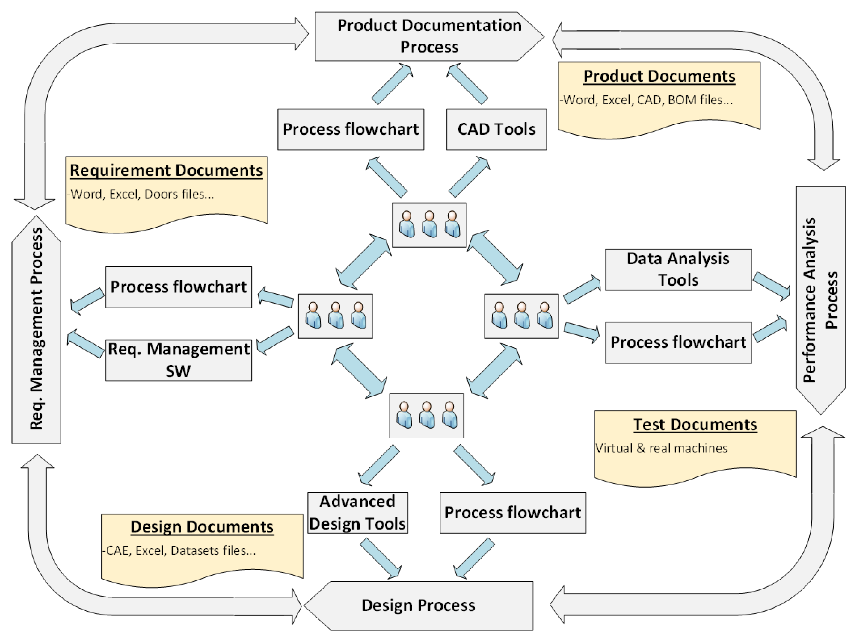
2. Standardization of Processes in the Electric Machine Domain, an Overview

Figure 1 summarizes the personnel, documentation, tools, and processes involved in the electric machine development process. Describing Figure 1, it is a fact that typically a design of an electric machine is defined by four types of documentation.
  • Requirements document: This document contains all the requirements for a particular electric machine and allows an understanding of what a product should do.
  • Design document: This is a technical document where the product definition of the electric machine is justified based on calculations of the different physical phenomena, applying sizing rules, using previous technical solutions for a similar design, using a solution that is standardized in benchmarking, etc. A good design document is essential to identify the reasons for a non-adequate performance during the testing phase or to improve the design in a future continuous improvement program.
  • Product definition documentation: This is a list of documents and drawings allowing to define the electrical/mechanical ratings (voltage, current, speed, input/output power levels, etc.) and to manufacture and mount all the pieces of the electric machines. Typically, it includes a bill of materials (BOMs), mechanical drawings, electric diagrams of windings, electrical schemas, and extra technical documentation.
  • Testing report: This is a technical document that presents the results of tests evaluating the grade of achievements of the performance requirements defined previously in the requirements document. A non-compliant result will derive from a revision of the manufacturing process or a revision of the design, needing to return to the design process. Finally, after some design iterations, if the design cannot fulfill the requirements, a new requirement agreement will be negotiated with the client.
Paper documents were the only means of presenting traditional designs. However, with the introduction of personal computers in the companies, the electronic documents were standardized, allowing them to write and draw them down, store all the information, and reuse all documents for new designs. Furthermore, advanced tools appeared to support the designer in managing and solving problems associated with the different design tasks. Among these tools, we have advanced tools to define, verify, and track requirements, tools to create three-dimensional (3D) definitions of the product model, design tools for high fidelity computation, and data analysis tools to compare different virtual designs.
In a product development environment, it is imperative to have powerful design tools, but it is also essential to have standardized processes to carry out the sequences of complete design tasks. This is much like the description of process standardization coming from Morgan and Liker [15] regarding the Toyota Product Development System claim that their highly standardized processes for product development allow creating highly stable and predictable outcomes (with both quality and timing) in an unpredictable environment. This necessity of standardized processes is directly applicable to the electric machine development environment. The design tasks for electric machines are complex related to a parallel multiphysics design (electromagnetic, thermal, mechanical, etc.) where several engineers could work simultaneously on parallel processes and whose results must be integrated. A time delay in a task-result can stop the workload of other tasks. Even worse, a computation error in one design domain (e.g., electromagnetic design) can imply severe consequences in a re-design of the other domains (e.g., thermal, mechanical). Therefore, standardized processes are needed to assure high-quality standards in each outcome and manage the iterations among the different sub-processes without uncertainties.
Some electric machine companies may already be at the point of having all the features implemented in their product development process. However, from studies it is known that not all the process is optimized sometimes because of new incorporations of personnel in the company that need training as well as the time spent on searching for information, previous studies say that for an engineer to retrieve information may take up to 70% of their time effort [16]. Here is where the KBE system can leverage the company’s knowledge resources in its design process, providing profit in time to put the product on the market. This paper encourages companies to go one step further and implement KBE systems to leverage its attributes to have time profit and reliable production. Figure 2 shows a conceptual KBE system framework for the design of electric machines. The figure defines a KBE application for each specific process, but different configurations can be implemented, grouping various processes.
Therefore, the industrial design of electric machines in this paper refers to obtaining electric machines through already validated components. This paper explains in more detail the design process in the following sections. This process is identified as suitable for a fast implementation of KBE systems in the electric machinery industry because the processes are well established; therefore, the knowledge is also already defined.

3. Methodology

The previous section described the basis for a company to consider implementing a KBE system for the development of electric machines. This basis relies on the standardization of processes. Typically, this either explicitly or implicitly is already in execution within an enterprise. Therefore, with the presumption that these processes are already standardized, first, this section presents the industrial V-model description proposing an organization of steps to insert the standardized processes. Later, the description of the proposed steps and architecture to develop the KBE system is presented. Finally, it shows a specific knowledge base structure and management in a SysML software tool to accomplish the targeted KBE application in multiple facets as the main contribution.

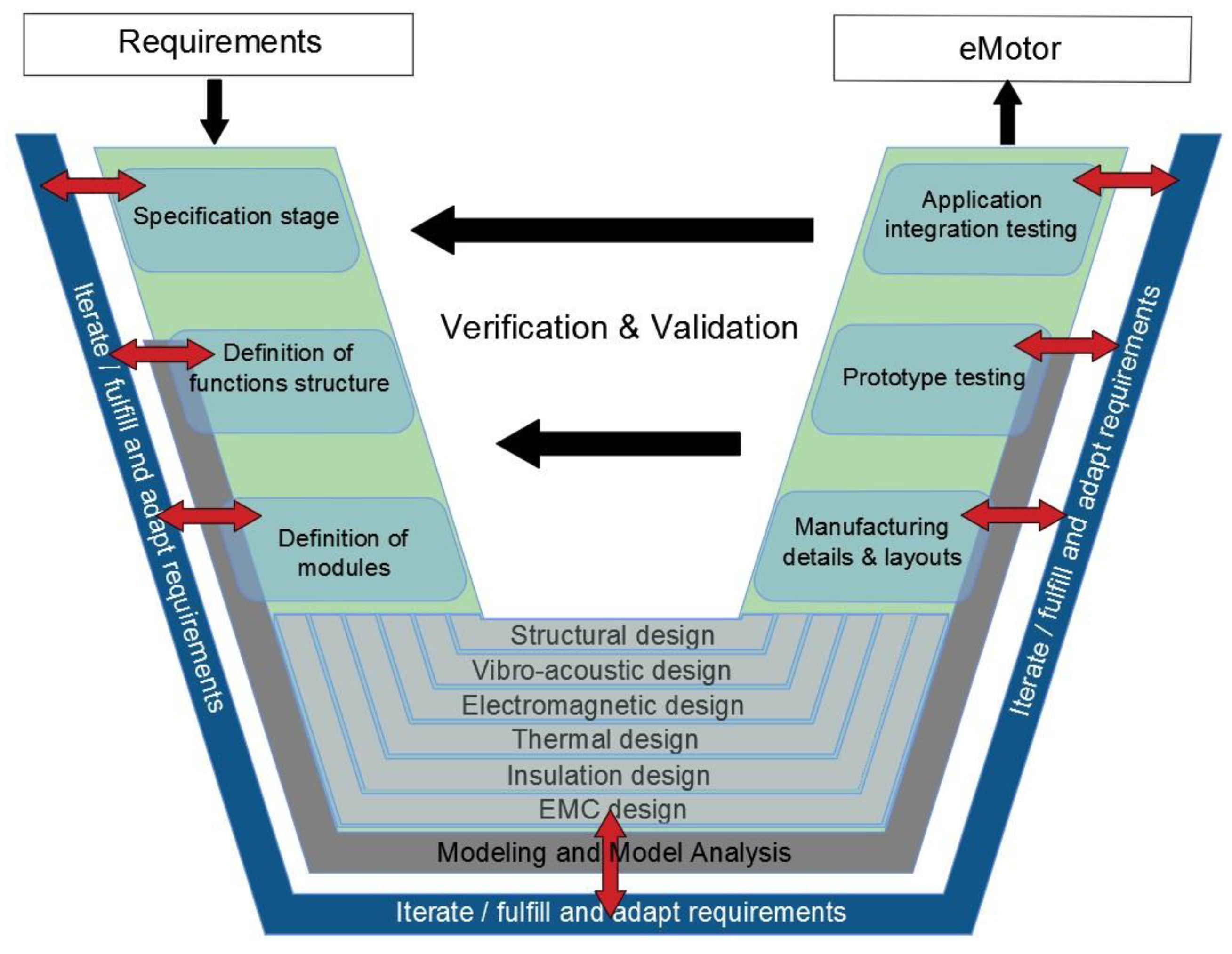
3.1. The Industrial V-Model for the Development of Electric Machines

It is worth remarking again that the design of an electric machine is a multiphysics problem with many technical and scientific issues considered at the same time for every specific design. Although there are useful multiphysics modeling tools, the full parametrization and modeling of a full multi-domain problem require massive efforts (including developing and testing laboratory prototypes). It is vital to use the previous know-how of state-of-the-art design and manufacturing technologies to reduce the design workload. It is considered difficult to introduce a new electric machine technology in the market without previously testing and calibrating the new design solution. Moreover, it is important to iterate these new design solutions with the manufacturing process. For this issue, experimental testing and calibration tasks are needed.
To accomplish a final industrialized electric machine product, in previous work [12], we proposed a three V-model methodology by merging VDI-2221/2206 standards. The model is divided into concept, component, and industrial V-cycles. The concept V-cycle encloses the process of transforming an idea into a physical motor concept. On the other hand, the component V-cycle encloses the process of transforming a concept into a virtual industrialized part. Both V-cycles share having high degrees of freedom for changes in design. The former has a greater degree of freedom than the latter. Although both can finish with a valid prototype, they still contain many features’ variants regarding the electric machine design to convert it into a final industrialized product. In other words, the knowledge regularly varies in these processes, and a KBE application could only provide limited support for specific micro-level processes. However, because the product is in the process of definition, it cannot achieve the macro-level objective of shortening the time to market as a final industrialized product.
Therefore, we propose using the industrial V-model presented in Figure 3 for the KBE application to transform the already validated models and components into an industrialized electric machine product, which means that processes and knowledge to execute them are defined. In this work, we show how to accomplish this during the implementation example. However, first, a more detailed description of the industrial V-cycle is given. This V-cycle is a process already followed by companies in the electric machinery industry. Each basic component is associated with a specific manufacturing process and equipment. For example, in electric machine manufacturing, a typical cost of the “tooling die” could be around the 200,000€ for 20 million strokes resulting in the manufacturing of 80,000 machines. Therefore, for a cost-effective fabrication, we can find the same die in the industry for different product ranges belonging to the machine developer. A typical cost-effective solution is to maintain the two-dimensional (2D) magnetic shape and extend the power level to increase the axial length and/or winding configuration.
This V-model attempts to embrace the development process providing a holistic view of the entire process and flexibility for industry adaptation. The V-model macro-processes were defined to group typical processes followed to develop an electric machine, so its adaptation to any enterprise-specific problem should be simple.
On the other hand, the micro-processes specific to different cases should be represented within each macro-process. The final goal is to develop a product that fulfills the specific requirements of the application of the client. One competitive target is to customize the electric machine to maximize the key performance indicators (KPI) that are more important for the client. At the same time, another competitive target is to reduce the time to put the new product on the market, trying to cope with the client’s business necessity. Therefore, this paper proposes to customize the electric machine design using a design space of standardized modular components using a KBE system that will allow a considerable degree of customization in a short time to market demands. The modules of the electric machine are selected, making sure they satisfy the customer requirements. Each part of the electric machine has defined manufacturing plans, materials, processes, mounting, etc. Therefore, after validating the prototype in the application, the electric machine can be manufactured in series.
In summary, the industrial V-model is proposed to obtain a fast time to market response with a cost-effective and reliable product. In parallel, to maintain competitiveness, the company should develop and validate innovative research products, allowing to update the industrial V-model with new enhanced solutions continuously.
The macro-processes for the industrial design context towards the KBE system development are now briefly described.
Specification stage: In this stage, the clarification and definition of the main performance data from the client’s initial requirements specification occur. The main idea here is to derive all the electric machine requirements that follow a repetitive calculation process and provide the freedom to adjust them. For the requirements not requiring computation, these should be input manually. The process of identification of the design requirements depends on the application. Therefore, an in-depth study and assessment of the application are required to derive the correct design requirements of the machine. For this reason, a requirement engineering framework is proposed in [13], describing the actors, processes, qualifications, and tools to complete this phase successfully.
Definition of function structure: The main function of the electric machine as an energy-transforming device is always the same. The focus should be put on variants of functions depending on the application. Depending on the operating conditions on the application and the electric supply of the electric machine, it can have different performances based on its components. Moreover, there could be different operating modes in the function of the protection signals and faulty cases. Normally, the client defines the different operating modes and conditions. The designer’s task will be to systematize all the information in a quantitative way using magnitudes of the electric machines and delimit the different functions that define a characteristic operating mode of the electric machine.
Definition of modules: Once the functions are set, the modules selection and arrangements that fulfill the functions are sought. This section considers the availability of materials, manufacturing processes, modeling tools, expertise, and others. The reuse of assemblies or subassemblies is implemented for faster design and manufacturing—for instance, the reuse of end bells, bearings, or stator and rotor lamination, and others. The degrees of freedom for selecting modules are subject to the degrees of freedom set on the function structure.
Domain-specific design: To allow cross-domain design and to cover all the electric machine features, this work proposes six domains: structural, vibro-acoustic, electromagnetic, thermal, insulation system, and electromagnetic compatibility (EMC). These six domains encapsulate the mechanical, electrical, and control engineering disciplines making the modeling process simpler to view, allowing concurrent engineering. Furthermore, even though each domain may follow a specific methodology, the integration of models is necessary to validate the motor solution.
Manufacturing details and layouts: This stage develops a complete manufacturing specification containing all the information for realizing the electric machine prototype. Examples could be detail and assembly drawings, bill of materials, encapsulation, impregnation, lamination cuttings (stamped or machined), transport and operating instructions, etc.
Prototype testing: As part of the development process, building a prototype is compulsory to validate the performance and verify compliance with the design requirements. Here is where testing starts to become relevant. For any application, it is essential to have a reliable and efficient operation of electric machines. Testing is crucial to judge the correct performance. In serial or mass production of electric motors, a series of tests are applied to each electric machine to ensure proper functioning. A variety of tests can be carried out with different purposes, such as optimizing the motor design, detecting faults, improving reliability, etc. Which tests to select depends on several factors such as cost, time, application, and reliability. It should be noted that for a personalized design in a short time to market competition, it will not be feasible to apply long-time reliability tests. Therefore, new procedures are required to reduce the testing time for each new personalized design. Modular designs and virtual validation techniques are new trends to reduce the testing efforts for each new design.
Application integration testing: This stage considers tests in the application system. The electric machine is integrated into the application to ensure correct performance. Validation of performance and verification of requirements in the application is the last stage of the development process. If the stage is considered successful, we end up with a valid motor satisfying the purpose for which it was built.
In conclusion, it is presumed that the know-how (standardized processes and components) is well established within each company regarding the industrial design context. If it is not, the standardization of processes and components is a previous step that should be accomplished before considering a KBE system solution for time profit.
Moreover, it should be noted that all the development process is supported by advanced modeling and design tools that leverage virtual design development. The scope of this paper is to demonstrate that these standardized macro-processes from which the knowledge is obtained can be transformed into KBE systems to support the industrial design of electric machines. The KBE system should provide the functionalities needed to obtain reliable machine designs in shorter periods.

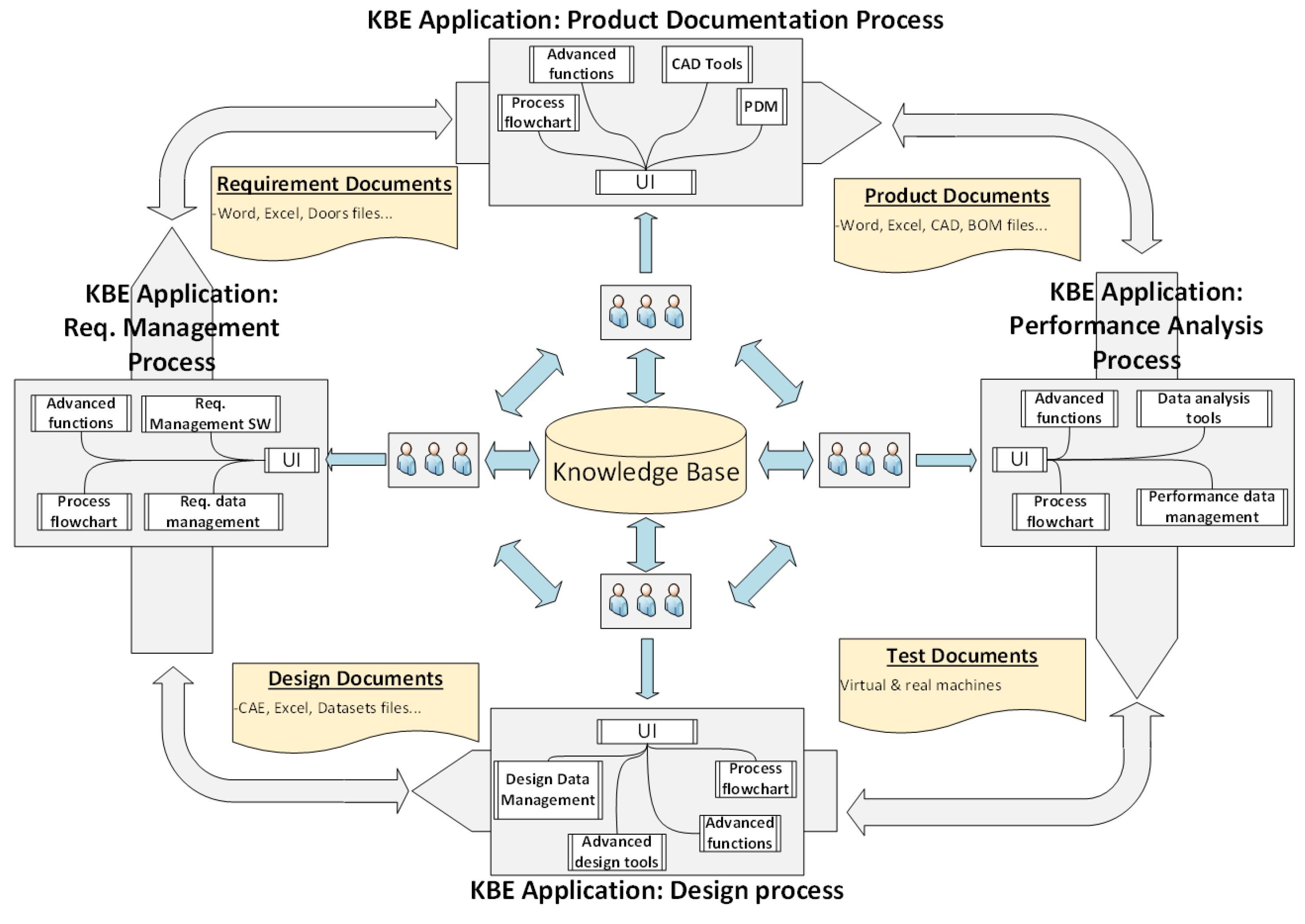
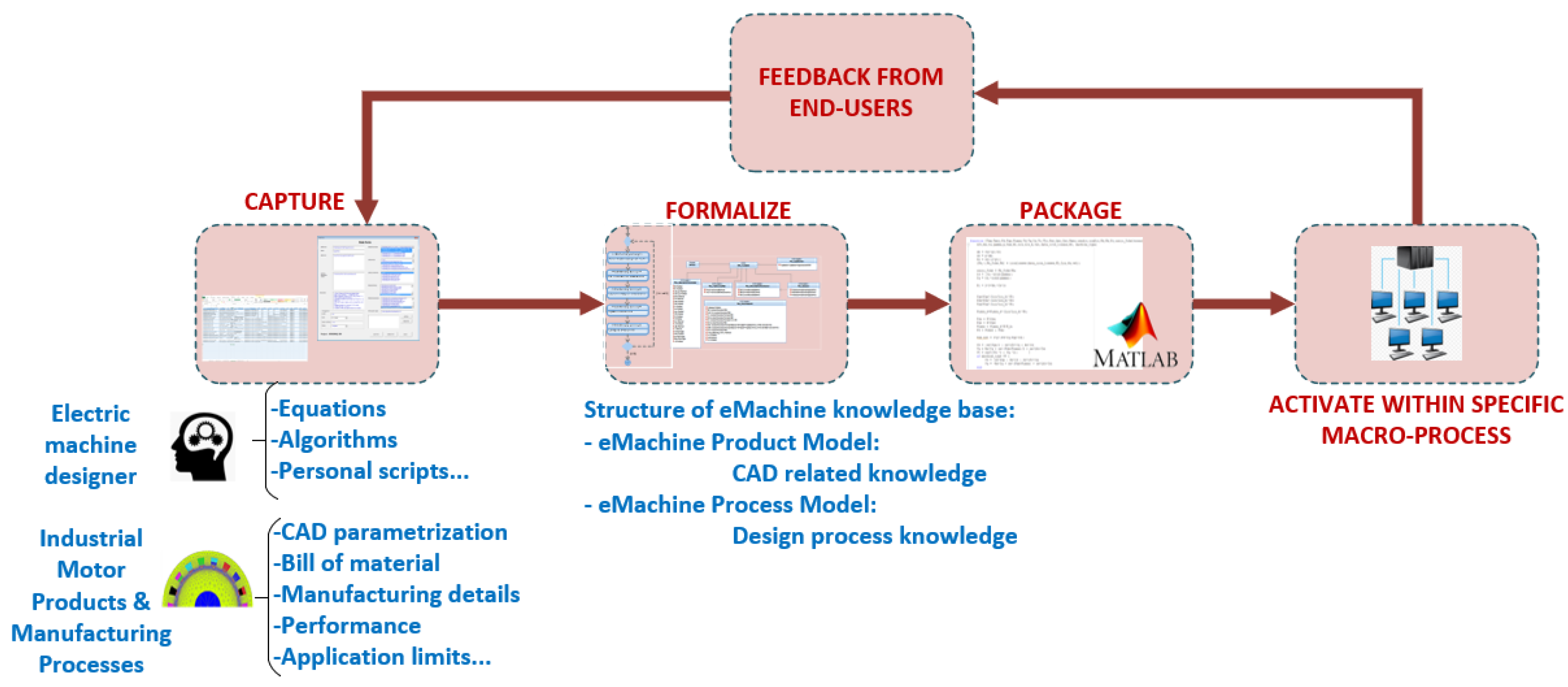
3.2. KBE System Development Process

This section describes the process followed for the KBE system development and its architecture. Figure 4 shows the process of developing the KBE system. Once the standardized processes to develop the electric machine are defined, the next step is to establish the requirements that the KBE application should accomplish. Once the requirements are set, further stages are the knowledge base generation and the package stage—finally, the KBE application incorporation into the development methodology.
The knowledge base generation stage aims to create the knowledge base used for the package stage, which is the development phase of the KBE application. The knowledge base generation stage includes the process of capturing and formalizing the knowledge. In this work, the knowledge base is created following MOKA methodology [17] implemented in a SysML commercial tool (IBM rational Rhapsody v8.3.1). The reason for selecting MOKA is that it is a neutral methodology that offers a well-structured knowledge representation language and processes for its capture and formalization (for more details on MOKA, see [17]). The knowledge should be gathered based on the requirements defined for the KBE application. The knowledge sources are electric machine designers and current industrial electric machine products from the company with standardized parts, reused for the faster creation of designs satisfying specific industrial application requirements.
The knowledge base comprises two types of knowledge representation models, the eMachine product model and the eMachine process model. The eMachine product models contain the relational information regarding the physical parts with structure, functions, materials, manufacturing details, and tests. Figure 5 shows an example of a structural model for the rotor lamination.
The eMachine process model comprises two knowledge hierarchizations, the macro-level and the micro-level. To provide some substantiation of the work, Figure 6 illustrates an example of this case. The knowledge base has been created following a top-down approach and a bottom-up approach for the package stage. All created models should be accessible to the designer through the KBE application, illustrated in Section 4 in the implementation section. Regarding this section, a high-level description of the knowledge base generation and package process is described. In future publications, more technical details regarding this part will be covered.
The reuse of knowledge through already-developed scripts by the designers was executed. It is known that companies already have software tools that are implemented within their standard processes. The KBE system should be flexible enough to integrate the software tools that the company is currently using. That will allow a smoother integration of the KBE system among the personnel already using the software tools and their processes. Hence, the proposed software architecture is presented in Figure 7. This architecture groups state of the art technologies mostly implemented in industry to cover the product development process. In other words, the KBE system consists of the integration of KBE applications with the rest of the technologies in the product development process. The architecture shows that the KBE application communicates with the other technologies through middleware. Of course, depending on the objective, some technologies may not be part of it.
Model-based systems engineering (MBSE) plus requirement management tools are used to support the development process, providing traceability of requirements and processes [12]. Product data management (PDM) centers on managing the design data of the product development process. This tool’s main contribution is to transform data into metadata, thus giving more information about it. Design tools include all those tools used in the design process, such as multiphysics and analytical tools. Finally, a common data repository is suggested for the KBE system to have all the data and information at hand for the entire development process.
Moreover, we suggest that the KBE system be built in multiple facets to gain feedback from the users in early phases to check if its implementation is worth going forward with or making the necessary adjustment for successful integration. In addition, Figure 7 shows that other KBE systems can be built and be part of a particular department (herein interested in engineering). The structure depends on the actors’ devised system; the architecture is flexible enough to adapt to any enterprise’s needs.

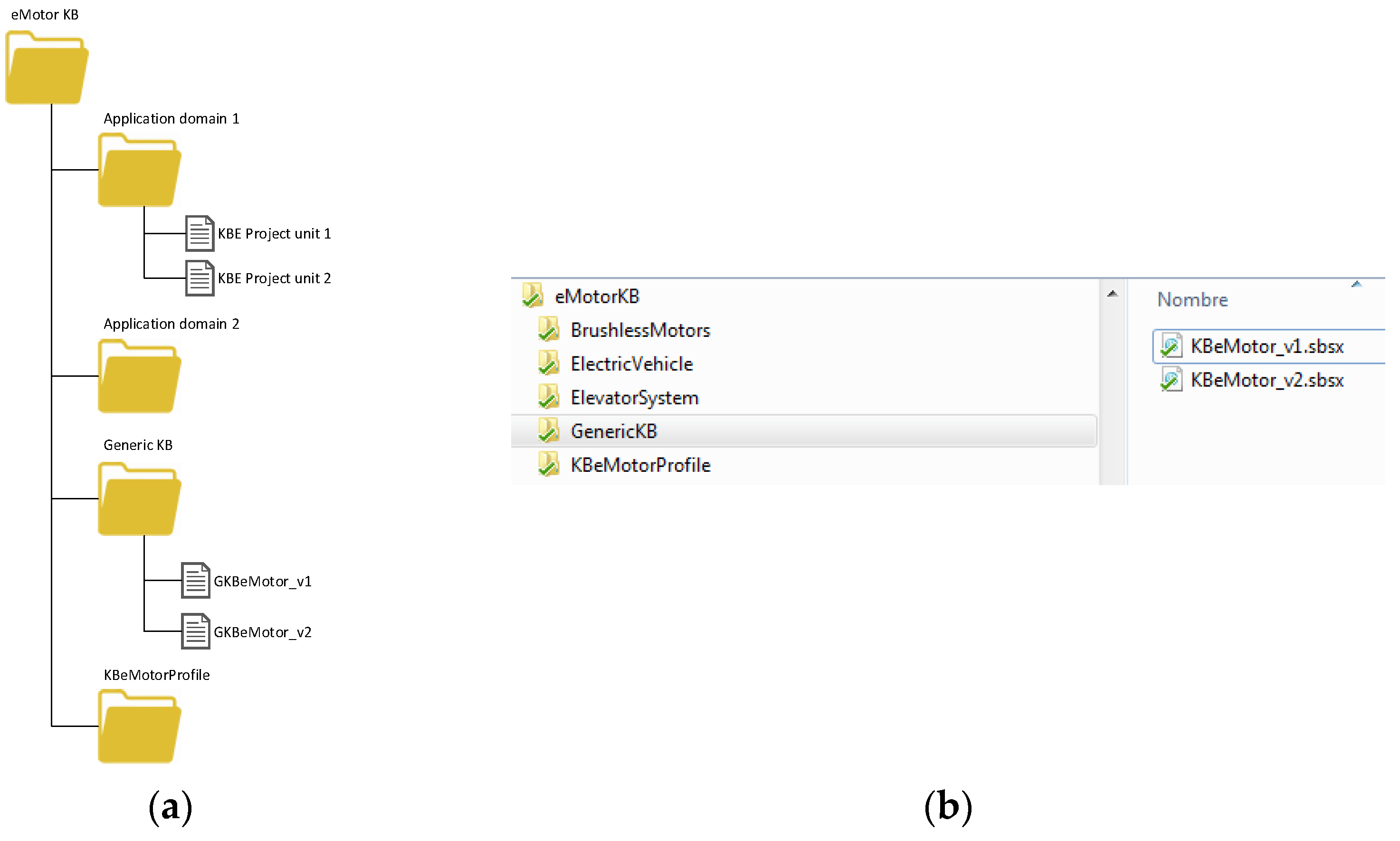
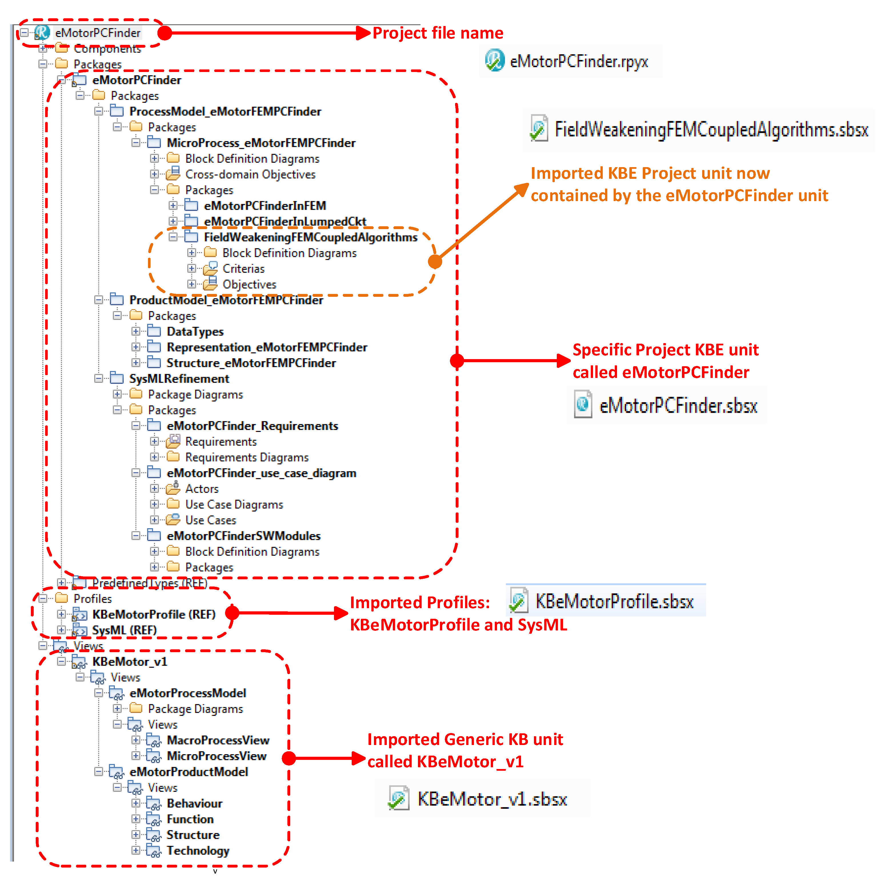
3.3. Knowledge Base Structure and Management

The interest of the proposed KBES framework is to develop KBE applications in multiple facets. Thus, the eMachine knowledge base (KB) increases while the number of KBE projects increases. Figure 8 shows the structure of the KB. The figure shows the eMachine KB consists of the generic KB and the application domain KB. Different applications domains (electric vehicle, elevators system, etc.) can be part of the KB. The KB is composed of units, every unit is part of the KB, and any specific project can use a unit. The KB organization in units is derived from the implemented tool in this work, IBM Rational Rhapsody v8.3.1. A unit in Rhapsody is a file in which the modeled information is stored. Different types of units can be created in Rhapsody. However, only package units are of interest to the concept of this paper.
Regardless of the selected tool used, for this work’s interest, the unit is a file containing part of the formalized knowledge of the eMachine KB. The two types of units, the generic KB unit and the KB unit for a specific KBE project, can be seen enclosed in the figure. Every specific KBE project is a type of KB unit for a particular application domain.
This paper recommends that when beginning from scratch (i.e., when no KB exists), the starting point should be creating a generic KB, preferably from the company’s eMachine product portfolio. That would make the knowledge engineer familiar with the knowledge domain and with this KBES framework. The generic KB should contain general knowledge about the enterprise’s electric machines, i.e., the knowledge that can be used in a KBE project irrespective of the application domain. Therefore, with the support of the eMachine developer (experts), the knowledge engineer is accountable for deciding what knowledge will be part of this KB unit. The creation of the generic KB facilitates reusing the knowledge gathered and modeled in new KBE projects.
Every KB unit contains the product model and process model. The generic KB imports knowledge from specific KBE projects. A KBE project may use entirely or partly the knowledge withheld in the generic KB and the knowledge withheld in another KB-specific KBE project from the same application domain type. Finally, it is important to clarify that the generic KB is not a KBE project, although it can contain complete KBE projects. These units are derived from packages, then every unit stored in the repository can be imported as a package within the SysML tool.
The organization of the units within the repository may follow a similar structure to the KB, as illustrated in Figure 8. To provide an example, Figure 9a shows the folder organization containing the KB units. Figure 9b shows a screenshot of the generic KB folder containing two versions of units for the generic KB named KBeMotor_v1 and KBeMotor_v2. (The file extension for the units in IBM Rhapsody is –sbsx–).
The structure of a SysML tool project is demonstrated in Figure 10 (the structure can be applied in all model-based systems engineering tools). Within the project file, the units should be arranged, as shown in the figure. On top, we have the specific KBE project unit (called eMotorPCFinder in the figure), followed by the profiles (SysML and KBeMotorProfile) and finally the generic KB unit (called KBeMotor_v1 in the figure). The same figure also gives an example of a KBE project using the formalized knowledge from a previous KBE project, demonstrating the advantage of knowledge reuse by structuring them in units. That is, the units can be imported as needed for specific KBE projects.
In conclusion, the KB structure is decomposed into a generic KB unit and specific KBE project units. The generic KB unit holds general knowledge from the eMachine product model and eMachine process model reused by any application domain. All units may contain the product, and process models, the organization of the units as files should follow a similar structure that allows the knowledge engineer to import any desired unit into a new project. The project organization within the SysML tool is as illustrated in Figure 10. The recommended order that should be followed, from top to bottom, is KBE project, profiles, and generic KB.

4. Use Case Example: KBE System Implemented for the Elevator Industry Domain

First, it is essential to clarify that the KBE application is developed for an electric design department’s specific problem with the design group knowledge. Due to the convenience, the electric design department specializes in the design of elevator motors. The implementation is developed for this specific field of application. Nevertheless, the description of features is generalized for its adaptation to any problem. Therefore, the reader should bear in mind that not all the presented features may be of his/her interest, or he/she can expand them for any purpose.
For the case study, the need to provide fast, viable electric motors that adapt to specific elevator system requirements by customizing validated models of motors with defined manufacturing processes has been identified. It was concluded that designers follow repetitive and well-established technical steps to accomplish the goal for a viable motor solution given a set of requirements that depends on a particular elevator system. Furthermore, each designer retains his/her knowledge to provide a solution, making the transfer of knowledge to new co-workers complicated and time-consuming. For all these reasons, the creation of a KBE system solution suits well the problem context. Therefore, this section presents a KBE system developed for the elevator industry domain. Its main goal is to provide a viable electric motor design solution based on previously validated designs and manufacturing processes used as references to satisfy new elevator system requirements.
The knowledge base generation stage is carried out using MOKA methodology. The informal model is implemented in Microsoft Excel, while the formalization step is implemented using IBM Rational Rhapsody v8.3.1. The package stage is carried out with this knowledge that allows the creation of intelligent algorithms [14] and knowledge models shown in each stage.
Only the electromagnetic and thermal domains are considered in this implementation example. The other domains and manufacturing processes are implicitly considered with the reuse of previously validated motor models. For a new elevator system, only these two domains must be adjusted. The right performance of the motor for each design domain is assured this way. The application integration testing phase is not considered in the developed KBE application. The software of the KBE application is developed using modular programming to facilitate its maintenance and upgrading. For each stage presented in Figure 3, one module is created. The modules are prompted automatically according to the progress of the project.
Regarding the architecture of Figure 7, the KBE application, called “eMotor Design Assistant,” is developed in MATLAB App Designer. The reason for selecting MATLAB is that the end-users are knowledgeable about coding in it, which allows the inclusion of features such as customized functions. For instance, in the developed SW, the end-users economic cost function has to be coded in the same KBE application (check the domain-specific design stage).
Even though it is technologically possible, no middleware is developed for automatic integration among the PDM systems (Aras innovator and Synect) and MBSE tool (Rational Rhapsody and Rational Doors) with the KBE application in this first version of the software. Thus, the metadata should be updated manually for the former and the models for the latter. However, the data and files related to these software are stored in the data repository from where the KBE application reaches them. The files are the eMotor database (containing the motors’ properties within the portfolio), the bill of materials, multiphysics models list, and layouts. Middleware was developed to accomplish automated tasks between the design tools (Flux and Motorcad) and the KBE application. The same applies for the data repository and the KBE application.
The user interfaces for each stage has the same structure. Figure 11 shows this structure. It is composed of the project name, controls that give the capabilities of moving through different stages, access to the know-how of the macro-process, and creating notes saved for the specific stage. Figure 12 illustrates how the controls give the possibility of accessing the know-how and the creation of notes that can always be reviewed. It also includes a timer that tracks the time spent in each stage; it is mandatory to turn it on since pressing the start button enables the module’s functions. It is also composed of a working directory explorer, the KBE application creates a folder in the given path of the data repository for each stage, and all files created in each stage are stored within the folder corresponding to the stage. The body of the stage is the part of the module that offers the tools to accomplish the purpose of each stage. The standardized micro-process provides step by step what the designer should do to finish the stage successfully. Furthermore, it is an animated guideline highlighting in red the current step of the standardized micro-process. Finally, the last important aspect to remark is that some steps have an “M” beside them within the standardized micro-process, which means that it should be executed manually. The manual steps are processes that need the designer’s judgment. Therefore, the designer’s control of the entire process is not taken out. Only repetitive tasks are automated for his support. This paper centers on the presentation of the functionalities given only by the KBE application. Therefore, each stage of the V-model is now explained for the developed KBE application.

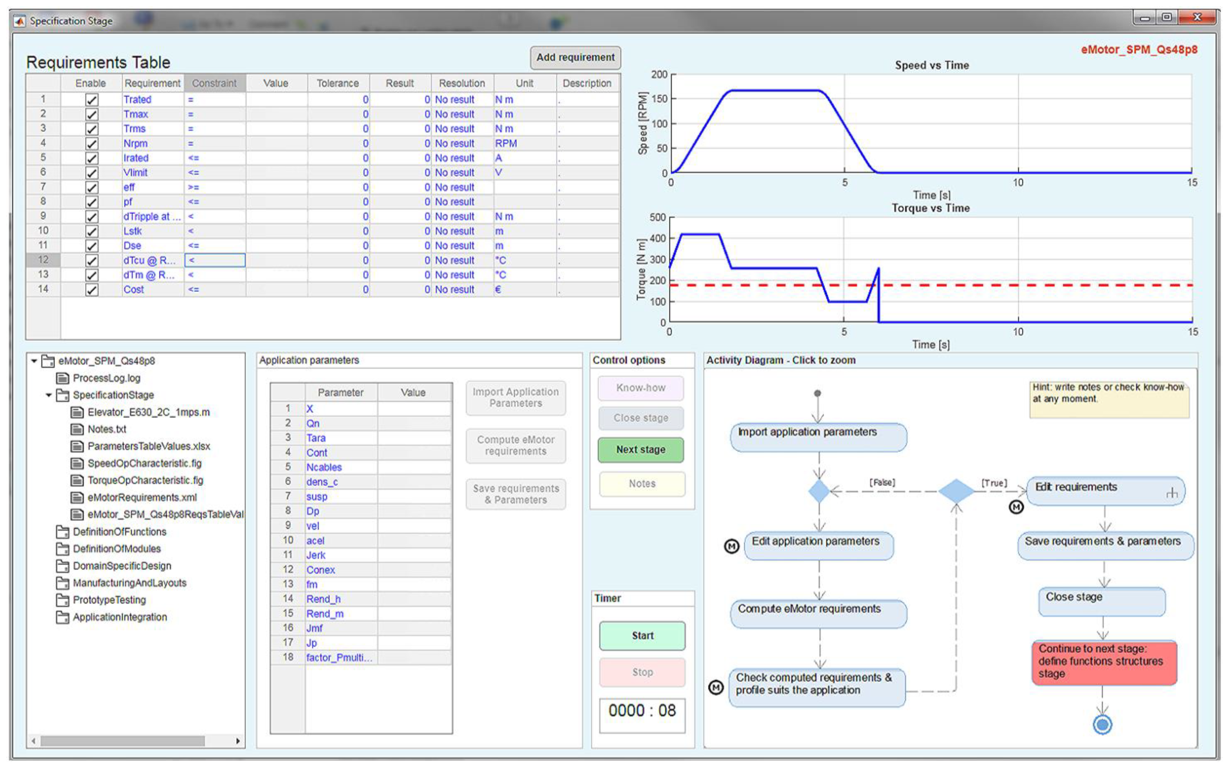
4.1. Specification Stage

Figure 13 shows the specification stage of the KBE application. The parameters of the elevator are imported and automatically displayed in the table of the user interface. The designer should follow the guideline to finish the process successfully. Some manual steps can be skipped if their execution is not needed. However, the designer’s options are still available to edit the parameters and compute the requirements for further analysis.
Furthermore, some requirements and characteristic curves are generated automatically. Nevertheless, the designer should fill the requirement constraints and values for the rest of the requirements that cannot be obtained automatically. If the requirement enable-field is disabled, that requirement is not considered along the entire process. The KBE application offers the option to create two additional customized requirements (add requirements button). Finally, the outcome of this phase is the files automatically created and stored in the working directory. In case the designer needs to return to this stage in the future, the KBE application will reload the data from these files and keep track of the process (in the background).

4.2. Definition of Functions Structure

In this stage, the goal is to limit the solution space. The designer limits the space of solution by the selection of properties of the motor. The importance of this feature can be visualized better when many motors are stored in the database. The designer selects the properties, the same properties imported from Aras innovator (PDM system). When the data is saved, the application checks for solutions in the database and creates a file for the next stage (in the background, i.e., not available to the end-user) with the motors that can become a possible solution. The only output available for the designer is a file with the selected properties to be used as a reminder, allowing replicability.

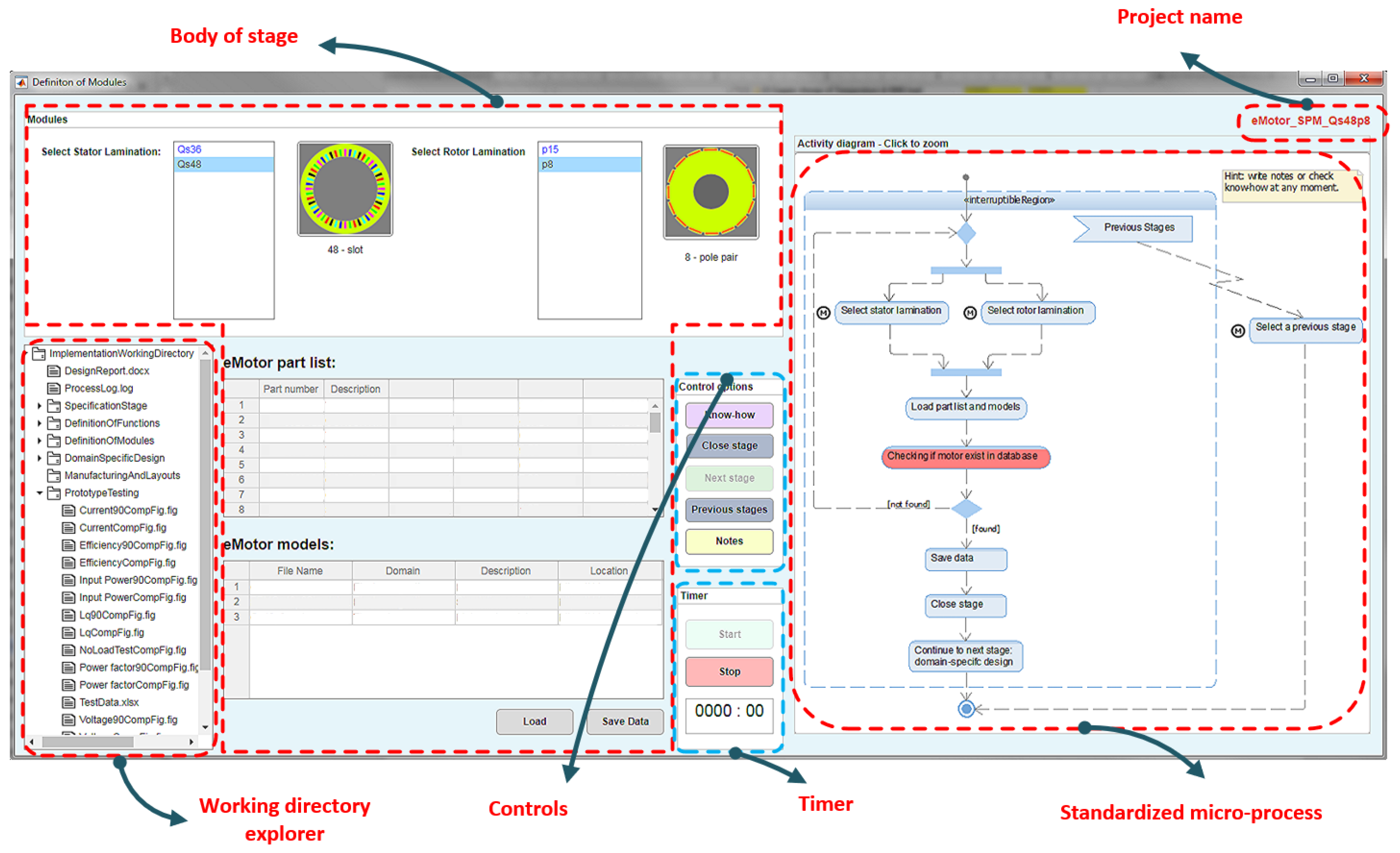
4.3. Definition of Modules

In this stage, the designer selects the stator and rotor lamination from the ones that appear available in each list. See Figure 11. The stator and rotor laminations available depend on the possible solutions found in the previous stage based on the designer’s properties.
The combination between stator and rotor lamination is checked upon the motor solutions, i.e., if the stator and rotor combination does not exist, the designer must select a new combination. After the selection is made, the designer loads the parts and models list and saves them by pressing the load and saving buttons. The KBE application automatically downloads the files using the links provided in the models list location field and stores them in the repository.
The output in this stage is the files containing these part lists and the electromagnetic and thermal models, and the simulation results (all obtained from the data repository, all linked to the PDM systems).

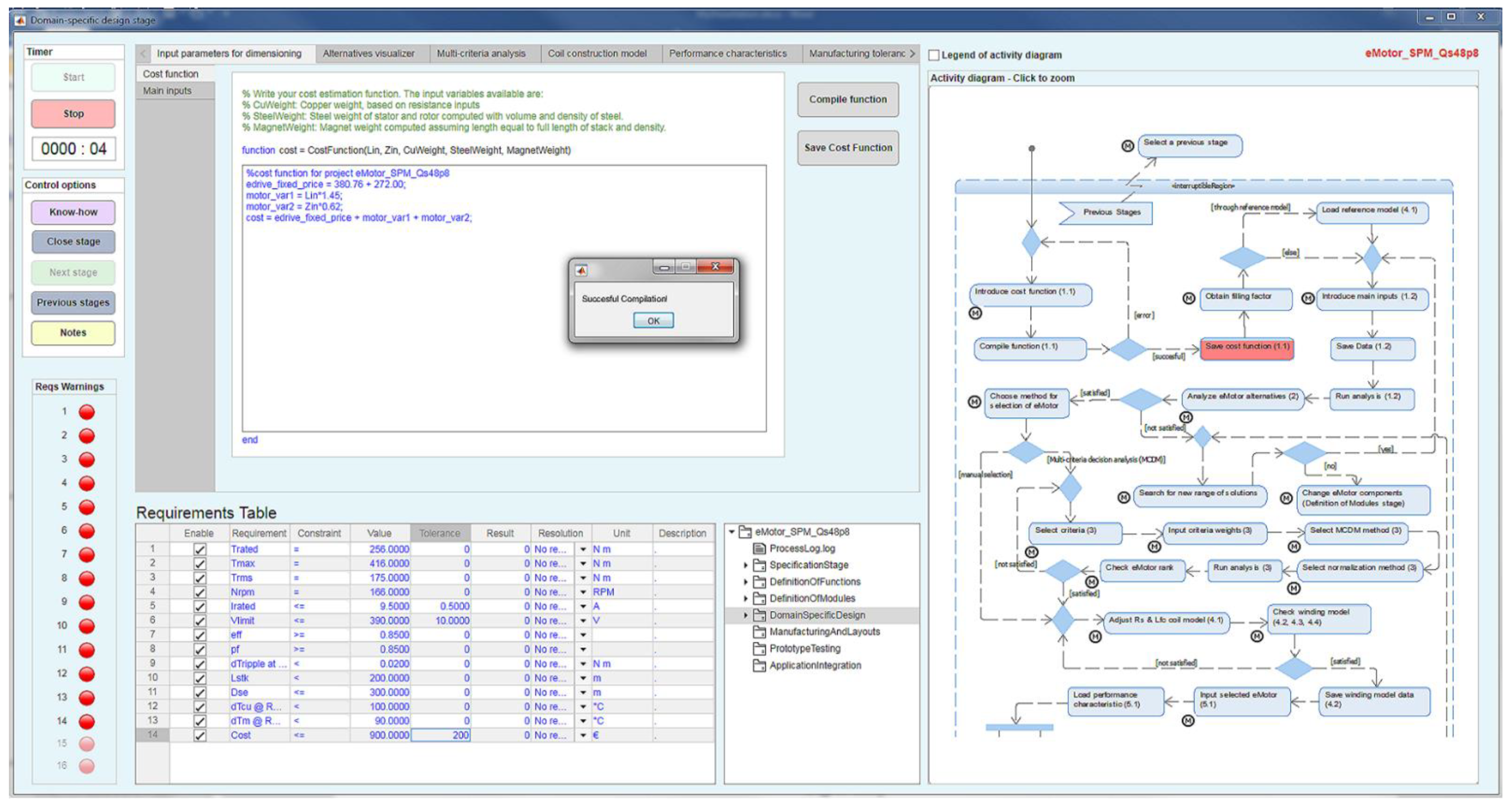
4.4. Domain-Specific Design

This stage involves many micro-processes. To provide a better understanding, these are grouped into six major processes. Figure 14 shows the user interface. It can be seen that it is composed of six main tabs corresponding to each major process. These processes are now described.
  • Cost function and sizing parameters: The tab “input parameters for dimensioning” holds two main features. First, the designer can enter a cost function through MATLAB code, see Figure 14. Inputs of the function are predetermined. During the search of solutions, this function is executed and compared to the cost (requirement) to check its viability. The other feature is in the subtab called “main inputs”, where the referenced values of the motor selected in the previous stage are loaded automatically. The designer can enter the length of stack values he wishes to check, i.e., a sweep of length from a minimum to a maximum value. He also has the ability to change any parameter of the referenced motor model regarding its material properties. After this, the main algorithm is executed, where for each length of stack solution, alternatives satisfying the requirements are searched by adjusting the number of turns per phase.
2.
Winding configuration: The tab name is “coil construction model”. Here the designer can change any configuration of the winding. The values of the referenced motor (data stored in the PDM system) can be loaded. The designer can then change the wires diameter, number of wires in parallel, number of turns per coil, span, layers, and others. The outputs are parameters that will be used to search for solution alternatives. Furthermore, it provides tools to check the star of slots as well as the winding factor spectrum and others.
3.
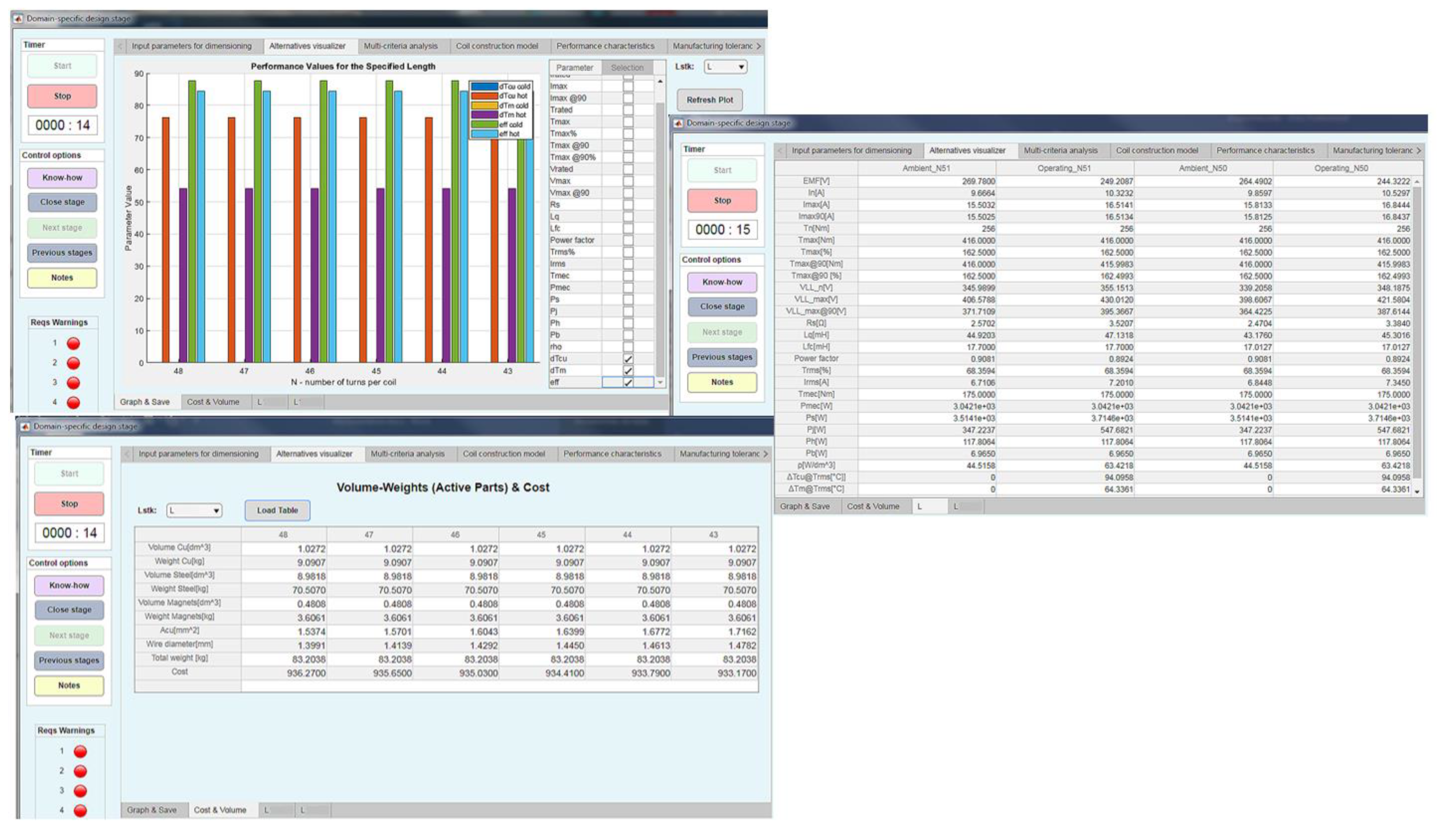
Solution alternatives visualization: The output of the previous processes are solution alternatives (if it exists for the given requirements). Next, in the tab “alternatives visualizer”, the designer can check the results. The tool provides the capability of graphing any selected parameter as well as table formats. The performance values of each alternative are given in ambient and operating temperature (from the thermal model). Figure 15 shows the tools. For each length of stack, several alternatives can be obtained, one for each number of turns per coil.
4.
Multicriteria analysis: The KBE application provides four multi-criteria decision-making methods (MCDM) to support selecting the best solution alternative. Of course, the designer has the freedom of not using it and selecting it by his/her judgment. The methods are the Technique for Order of Preference by Similarity to Ideal Solution (TOPSIS), Weighted Sum Model (WSM), Weighted Product Model (WPM), and Weighted Aggregated Sum Product Assessment (WASPAS). For references, please see [18,19]. The designer has the option of selecting the criteria (nine available: rated current, maximum current, efficiency, copper temperature, magnet temperature, cost, length, voltage, mass) and inputs their weights according to his judgment. The performance scores are computed based on the weights and the method selected. The output is a list sorted in descendent order.
5.
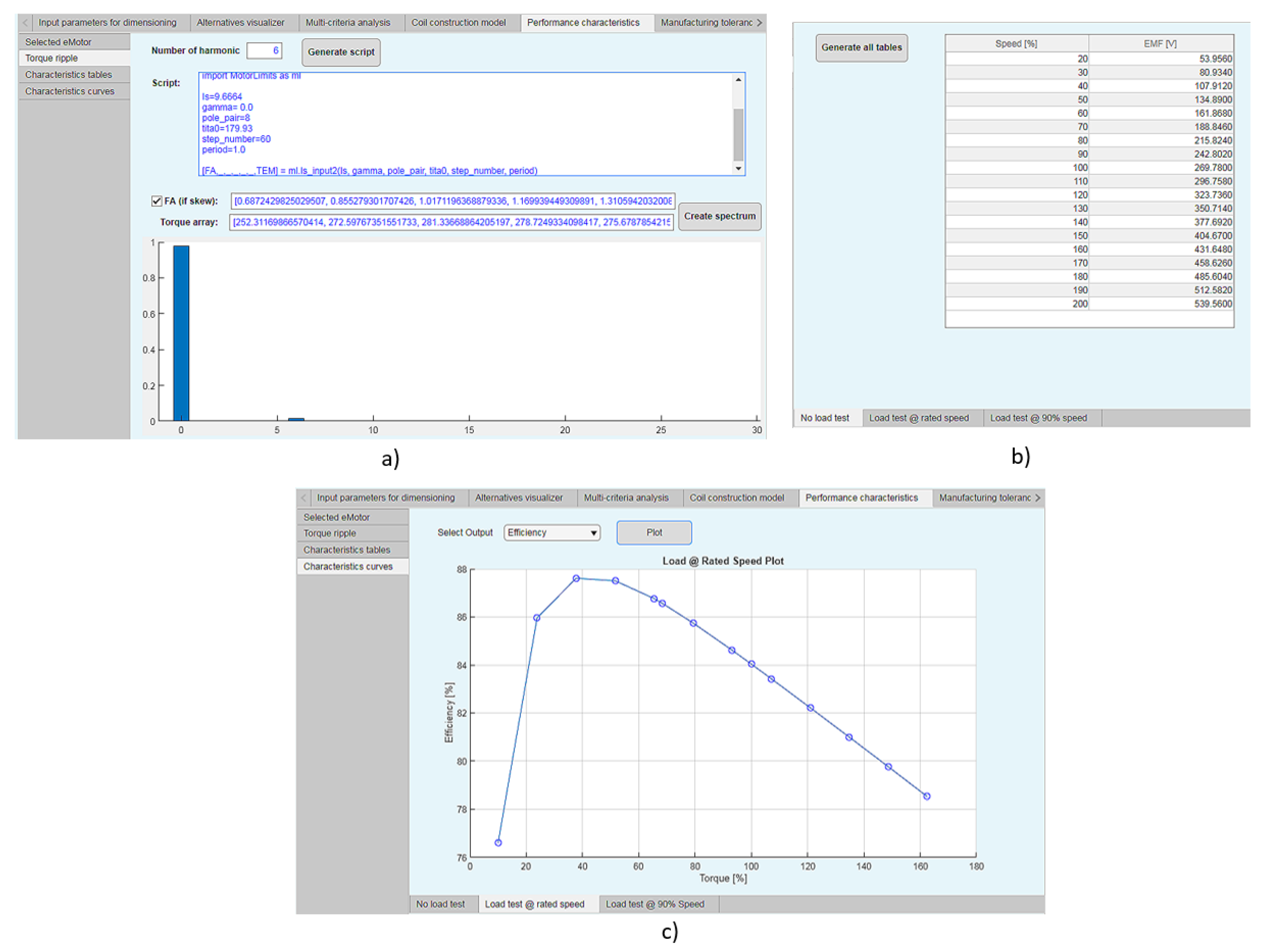
Performance characteristics: The characteristics curves of the chosen motor solution are computed. The data is available in both formats, curves and tables. These characteristics are later compared with the curves of the prototype testing stage. Figure 16 shows some of these features. Once the motor solution is selected, the requirement results column (Figure 14) is filled out automatically with the performance values. Based on the results, the resolution column is also filled out automatically. This column states if the requirement passed or failed. It also shows the warning lamps that turn green on the left if the requirement is satisfied or red if it is not. However, a forced passed option available in the resolution column allows the designer to pass the requirement even if it does not satisfy the requirement value, turning the lamp yellow if this case is selected. Examples are illustrated later in the prototype testing user interface (where the data values were intentionally omitted). The designer cannot modify the requirement values in this phase. He must return to the specification stage to do so.
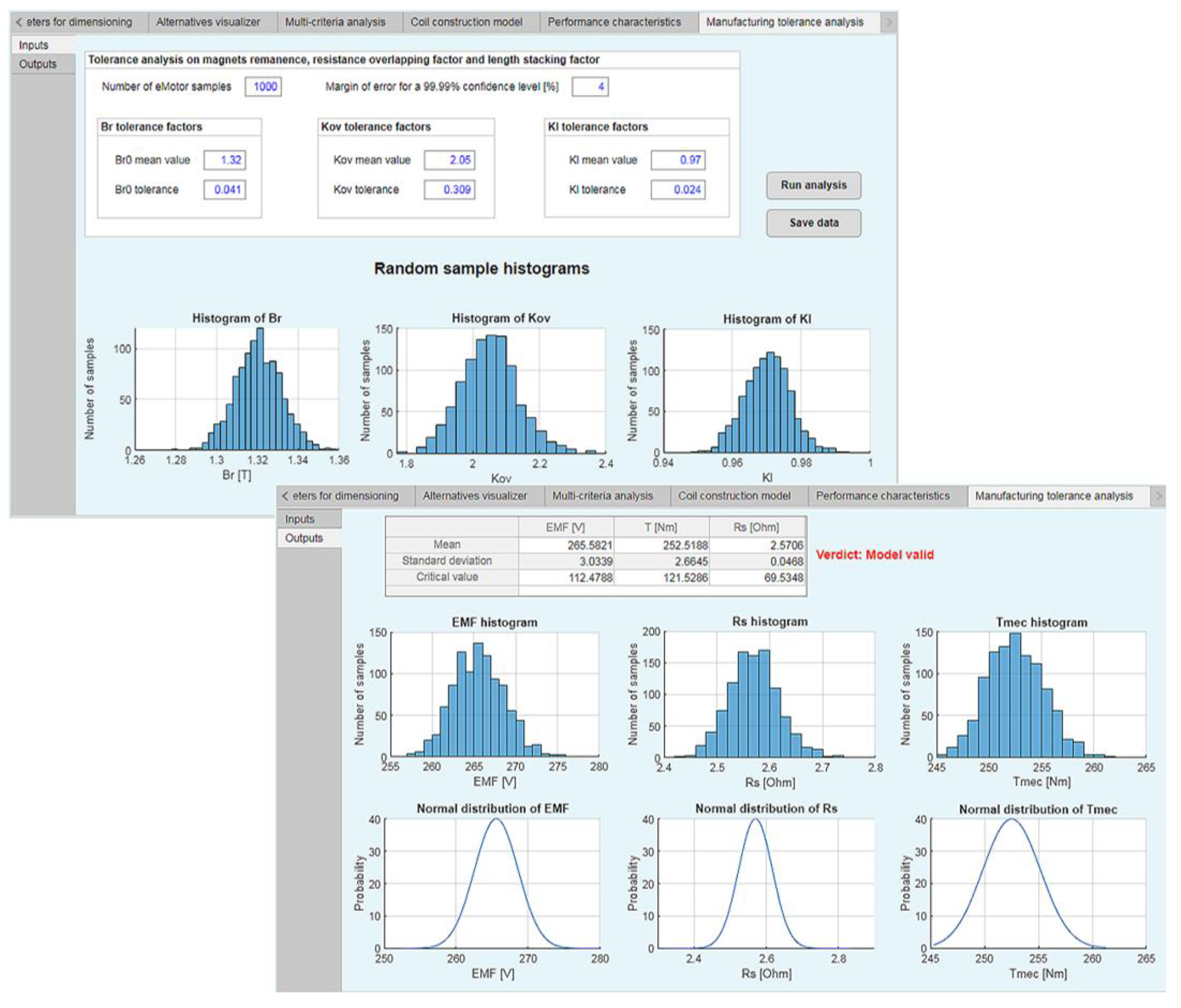
6.
Manufacturing tolerance analysis: The last step of the design phase is to check the manufacturing tolerance based on three design variables, magnet remanence (Br), stacking factor (Kl), and overlapping factor (Kov). The selection of these variables is a consequence of Gomez’s sensitivity analysis in [20]. In summary, it analyzes statistical distributions of the machine performance considering serial-production tolerance variations, therefore obtaining critical values that support the designer on the decision whether the design is valid or not. The designer enters the number of samples units, and the margin of error for a 99.99% confidence level. In addition, the mean values of each design parameter and the tolerance for each parameter are entered. After this, the analysis can be executed and the data saved. Figure 17 shows the user interfaces of this part of the KBE application. If the critical value is greater than 3.62, the design model can be affirmed as valid. On the other hand, if the critical value is below 3.62, the defective machines should be obtained through the standard normal distribution probabilities.
All files created within the previous processes are saved in the domain-specific design folder in the data repository, where the designer can always reach them at any time. Finally, the domain-specific design stage is closed, and the designer can proceed to the next stage.

4.5. Manufacturing Details and Layouts

In this stage, the designer selects one manufacturer from a drop-down list (manufacturers that work with this particular design department) to download the templates and layouts available from that particular manufacturer. After filling the templates and customizing the layouts properly, the designer can import them. Importing the templates and layouts through the KBE application helps keep a record of the process, and the imported files become part of the final design report. All files are added to the stage folder and can be visualized in the explorer.

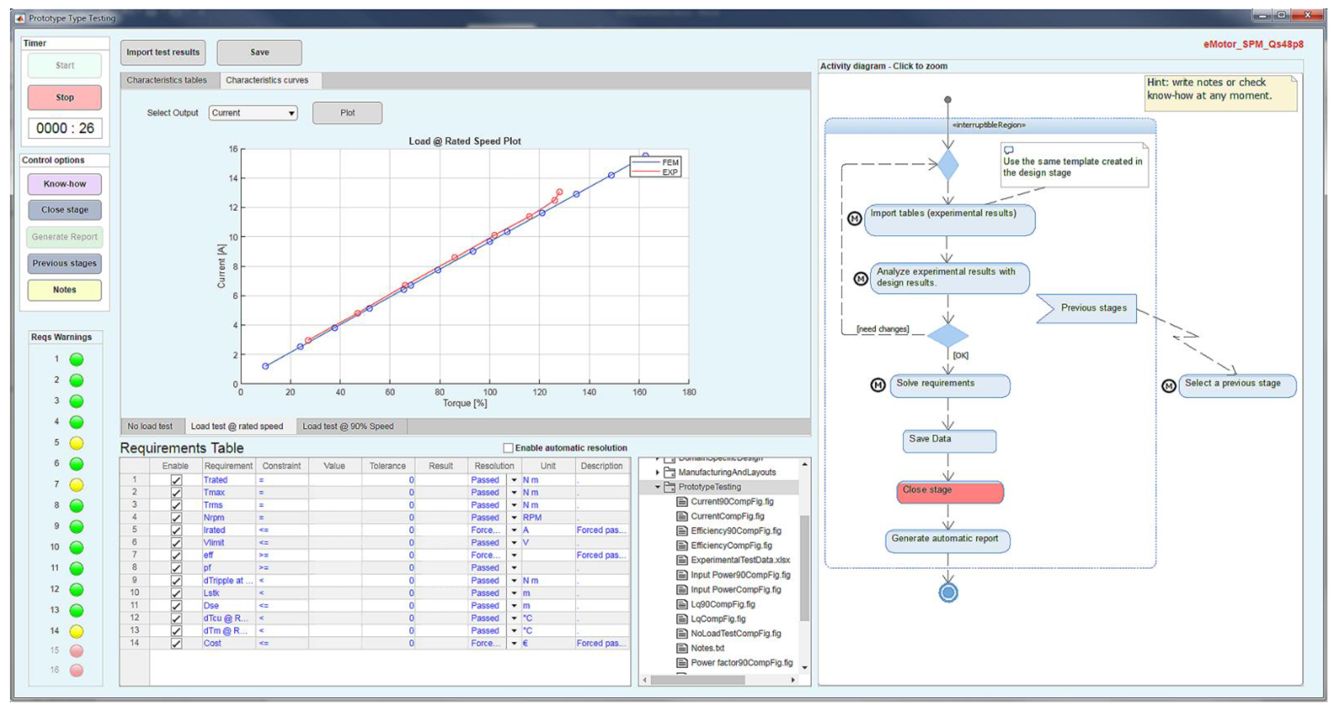
4.6. Prototype Testing

Prototype testing is the last stage where the KBE application brings support to the development process. After the experimental tests are carried out, the test data can be imported using the KBE application. The same format created in the design phase for the selected motor results must be used. The KBE application makes a comparison between the designed and tested results. As in the design phase, the requirements table is filled out automatically based on the imported test results. Figure 18 shows the user interface of the prototype testing phase. The KBE application provides the ability to visualize the comparison between design results and test results through plotted curves for each characteristic (current, voltage, power, efficiency, etc.) and in table format.
After closing the stage, the generate report button is enabled (see Figure 18), and the KBE application ends its support by creating a detailed report in MS Word for the designer with the process he/she followed in all the development processes. At the end of the entire process, a reliable electric motor design is obtained for the specific elevator system.

5. Results and Discussion

During the implementation of the developed KBE application, “eMachine Design Assistant,” many features were changed back and forth until the final functionalities that satisfied the designers’ objectives (obtained from their knowledge) were reached. Therefore, as a result, we present and describe these functionalities using as reference the herein developed KBE application, attempting to show, however, that these functionalities should be devised for new KBE applications for the electric machine development process to shorten the time to market.
The main functionalities are grouped into four categories: process traceability, accessibility to knowledge, automation of tasks, and intelligent support to the designer. Each category is now described.

5.1. Process Traceability

The KBE application tracks and traces the development process from start to end. The controls (see Figure 11) provide the possibility of going to a previous stage or closing the current stage to the next stage.
Moreover, requirements can be traced and verified during the entire process by showing the values on the user interface and saving the table of requirements as a document available in the data repository. For instance, if the designer needs to return to the specification stage because a change to a requirement must be done, previous requirements are archived. Thus, a historical of requirements is always maintained. Similar is done with the storage of parameters and values, results, and events in each stage. The KBE application provides the capability to resume the project where it was left. The animated guideline in each stage highlights in red the current micro-process where the designer stopped. The guideline is an animated activity diagram remarking in red the current step of the stage for tracking and assurance all actions are made.
Furthermore, the KBE application has a timer that registered the time spent on each stage; the user can stop and start the timer to register only working time. The working time is accumulative. Then, when the stage is closed and later resumed, the timer starts where it was left. The events on each stage are always registered in a log file with a defined structure available to the user.
Finally, at the end of the process, the KBE application generates a design report with information about each stage. For instance, selected properties and parameters, graphs, saved notes, motor solutions with layouts, manufacturing details, and a complete recapitulation of the development process with the metrics of time spent on each stage, revisits made to each stage, and more.

5.2. Accessibility to Knowledge

The KBE application provides the capability of retrieval of knowledge, information, and data. The KBE application integrates the knowledge saved in models with easy access to the user for context understanding for each stage as well as for the whole process. The standardized micro-process, which is also formalized knowledge, is presented as an animated guideline for successfully finishing the phase. Finally, all files are created and saved in the data repository for easy retrieval.

5.3. Automation of Tasks

The features can be summarized as:
  • Intelligent algorithms as an outcome from the knowledge provided by the experts that automate complex tasks such as the search for electric motor solution alternatives based on the given data (requirements, parameters, modules, etc.).
  • Automatic requirements verification and filling of forms.
  • Automatic presentation of results.
  • Automatic simulations and file generation.
  • Automatic cost analysis.
  • Automatic comparison of results (design and experimental).
  • Automatic final design report in MS Word format.
However, tasks that require the judgment of the designer were left manual.

5.4. Intelligent Support to the Designer

In this category, the features given by the KBE application are:
  • Intelligent search for solutions alternatives.
  • Animated guideline.
  • Multi-criteria decision making (MCDM) methods for the best alternative based on the designer’s criteria.
  • Visualization of results (curves, tables, etc.).
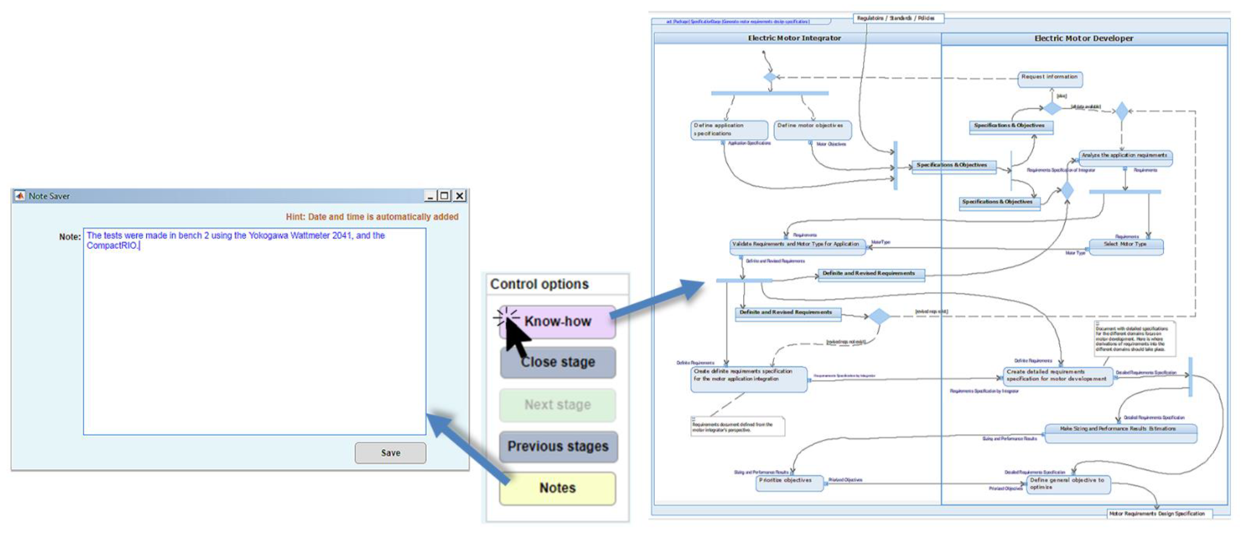
  • Creation of notes
  • Manufacturing tolerance analysis tools in the design phase.
  • Hints of design, warnings of requirements, as well as for variables out of range.
It is important to add that the final report also includes a summary of metrics such as time spent on each stage, start and ending dates, revisits to each stage, and the project’s total time from its opening until its closure. That allows measuring the performance of the designer with the KBE system through this data. The data is retrieved automatically from the log file created by the application to record all the events throughout the development process.

5.5. Working Time Consumption Comparison with and without the KBE Application

Working time consumption comparison with and without the KBE system is made for a straightforward design without time spent due to changes in requirements or any other tasks that could slow the process. Table 1 shows the time consumption comparison reflecting the advantage of implementing the KBE system. In the use case example, a reduction of up to 76% could be achieved.
The major reasons for a faster development process are not only due to automation of repetitive tasks but also that the information is at hand in every stage, i.e., the designer does not have to spend time searching for any type of data and information. It is important to remark the time shown in the table is the total working time spent on the steps presented in the standardized micro-processes (guidelines) on each stage, so tasks outside these actions are not considered. For instance, the prototype testing stage also involves making the tests, which requires many hours of work, especially for thermal tests. Therefore, the time presented in this stage is only time spent on analyzing data as presented in the activity diagram in the prototype testing stage. The same applies to the rest of the stages.
In summary, this paper described an implementation example of a KBE system capable of achieving faster designs of industrial electric machines. This work identified the macro-processes regarding the reuse of validated components as an opportunity for companies in the electric machine industry to take a step forward to implement KBE system in their current processes. Therefore, the industrial design of electric machines includes many repetitive tasks that can be automated; however, the knowledge should be formalized before applying it in a KBE system. The results obtained in this work (shown in Table 1) proved the advantage of implementing this type of KBE system in the industrial V-model for time consumption reduction for the electric machine development process. Although the comparison was made for an ideal straight forward design (i.e., no macro-process was repeated), for the use case example, the result shows that a time workload reduction up to 76% is achievable, not only upon the automation of repetitive tasks but also because the information is at hand at every stage. One additional feature to highlight is that by following the same process, the designer can create several projects at the same time. This allows the execution of projects in parallel to compare different motor solutions based on distinct models, i.e., different combinations of stator and rotor laminations.
Certain skills are still necessary to devised and implement a KBE system. Nevertheless, this paper shares a practical implementation to encourage stakeholders that even though some tasks may seem complex, they can be simplified through KBE systems to profit time. In this way, the designer can spend more time being creative and not worrying if computation was done correctly or if he/she misses a step. The macro-processes herein presented were synthesized for the understanding of any electric machine designer. The main functionalities that the KBE system provides were grouped as development process traceability, knowledge accessibility, automation of tasks, and intelligent support, to show what should be targeted in a KBE system for the electric machine design domain.

6. Conclusions

The previous sections provided the description and results of a KBE system to support the faster development of industrial electric motors ensuring all knowledge, information, and data is not lost through the whole development process. An implementation example was developed for the elevator industry domain. The devised KBE system provides the functionalities of the development process traceability, knowledge accessibility, automation of tasks, and intelligent support to the designer. Comparing the performance of the implemented KBE system to the process without the KBE system resulted in a relevant time reduction of 76% for the use case example, thereby demonstrating how designers could leverage KBE systems for faster development of industrial electric motors.
For the scope of this paper, the successful development of a KBE system for the elevator industry demonstrated that a KBE system offering these functionalities provides the user enough guidance for the development of a reliable electric motor, therefore, encouraging readers to seek these kinds of functionalities in their KBE system implementations.
In summary, the technical contribution of this article is the definition of a framework for the implementation of a KBE system for the electric machine domain that can serve as a guideline for KBE system developers and electric machine designers. Compared to KBE literature for electric machines, the contribution lies in the unified development of a KBE application using standardized processes and commercial SW, providing the knowledge base structure and management. Finally, this work also presents limitations on describing more functionalities for the prototype testing and manufacturing and lacking managerial guidelines to analyze costs and risks of a KBE solution in an enterprise. Further research should be executed in these areas.

Author Contributions

J.P. conceived the research; J.P. and C.A.R. designed the research; C.A.R. developed the framework and prepared the manuscript; G.U. and G.A. were sources of knowledge and validated the work. All authors have read and agreed to the published version of the manuscript.

Funding

This research received no external funding.

Data Availability Statement

Not applicable.

Acknowledgments

This work has been partially supported by the program: “Red guipuzcoana de Ciencia, Tecnología e Innovación 2017” from Diputación Foral de Guipuzkoa.

Conflicts of Interest

The authors declare no conflict of interest.

References

  1. Landy, C.F.; Kaplan, R.; Lun, V. An Expert System for the Design of 3-phase squirrel cage Induction Motors. In Proceedings of the Third International Conference on Electrical Machines and Drives (Conf. Publ. No.282), London, UK, 16–18 November 1987; pp. 127–131. [Google Scholar]
  2. Poon, H.L. A knowledge-based condition monitoring system for electrical machines. Comput. Ind. 1991, 16, 159–167. [Google Scholar] [CrossRef]
  3. Cross, G.; Blakley, J.J.; Shui, F. An Expert System for the Integrated Design and Test Result Diagnosis of Industrial DC Motors. In Proceedings of the International Conference on Electrical Machines, Manchester, UK, 15–17 September 1992; Volume 2, p. 460. [Google Scholar]
  4. Laugis, J.; Vodovozov, V. Expert System for Electric Drive Design. In Proceedings of the 13th International Power Electronics and Motion Control Conference, Poznan, Poland, 1–3 September 2008; pp. 1017–1019. [Google Scholar]
  5. Zhou, C.; Gao, L.; Liu, Z. Design and Realize the Electromotor Choice Expert System of Sewing Machine Based on UML. In Proceedings of the 9th International Conference on Electronic Measurement & Instruments, Beijing, China, 16–19 August 2009; pp. 1069–1073. [Google Scholar]
  6. Wei, X.; Qiong, Z.; Cheng, T. Design synthesis of permanent magnet synchronous motor based on expert system. In Proceedings of the 2010 IEEE International Conference on Intelligent Computing and Intelligent Systems, Xiamen, China, 29–31 October 2010; pp. 91–94. [Google Scholar] [CrossRef]
  7. Favi, C.; Germani, M.; Marconi, M.; Mengoni, M. Innovative software platform for eco-design of efficient electric motors. J. Clean. Prod. 2012, 37, 125–134. [Google Scholar] [CrossRef]
  8. Karnavas, Y.L.; Chasiotis, I.D. A simple knowledge base software architecture for industrial electrical machine design: Application to electric vehicle’s in-wheel motor. Adv. Intell. Syst. Comput. 2016, 432, 111–122. [Google Scholar] [CrossRef]
  9. Mayr, A.; Meyer, A.; Gonnheimer, P.; Gramlich, J.; Reiser, M.; Franke, J. Concept for an integrated product and process development of electric drives using a knowledge-based system. In Proceedings of the 2017 7th International Electric Drives Production Conference (EDPC), Würzburg, Germany, 1–7 December 2018. [Google Scholar] [CrossRef]
  10. Tüchsen, J.; Pop, A.C.; Koch, M.; Schleich, B.; Wartzack, S. Data driven product portfolio analysis of electric motors based on product platforms using knowledge-based systems. In Proceedings of the Design Society: 22nd International Conference on Engineering Design (ICED19), Delft, The Netherlands, 5–8 August 2019; pp. 2537–2546. [Google Scholar] [CrossRef] [Green Version]
  11. Van Der Velden, C.; Bil, C.; Xu, X. Adaptable methodology for automation application development. Adv. Eng. Inform. 2012, 26, 231–250. [Google Scholar] [CrossRef]
  12. Rivera, C.A.; Poza, J.; Ugalde, G.; Almandoz, G. A Knowledge Based System architecture to manage and automate the electrical machine design process. In Proceedings of the 2017 IEEE International Workshop of Electronics, Control, Measurement, Signals and their Application to Mechatronics (ECMSM), Donostia-San Sebastian, Spain, 24–26 May 2017. [Google Scholar]
  13. Rivera, C.A.; Poza, J.; Ugalde, G.; Almandoz, G. A requirement engineering framework for electric motors development. Appl. Sci. 2018, 8, 2391. [Google Scholar] [CrossRef] [Green Version]
  14. Rivera, C.; Poza, J.; Ugalde, G.; Almandoz, G. Field Weakening Characteristics Computed with FEM-Coupled Algorithms for Brushless AC Motors. Energies 2018, 11, 1288. [Google Scholar] [CrossRef] [Green Version]
  15. Morgan, J.M.; Liker, J.K. The Toyota Product Development System; Productivity Press: New York, NY, USA, 2008; ISBN 1563272822. [Google Scholar]
  16. Hirz, M.; Dietrich, W.; Gfrerrer, A.; Lang, J. Integrated Computer-Aided Design in Automotive Development; Springer: Berlin/Heidelberg, Germany, 2013; ISBN 9783642119392. [Google Scholar]
  17. Stokes, M.; Consortium, M. Managing Engineering Knowledge: MOKA: Methodology for Knowledge Based Engineering Applications; Professional Engineering: London, UK, 2001. [Google Scholar]
  18. Triantaphyllou, E. Multi-Criteria Decision Making Methods; Pardalos, P.M., Hearn, D., Eds.; Springer: New York, NY, USA, 2000; ISBN 9781441948380. [Google Scholar]
  19. Velasquez, M.; Hester, P.T. An Analysis of Multi-Criteria Decision Making Methods. Int. J. Oper. Res. 2013, 10, 56–66. [Google Scholar]
  20. Gomez, I. Design Methodology for Achieving Reliable Permanent Magnet Synchronous Machines. Ph.D. Thesis, Mondragon Unibertsitatea, Guipúzcoa, Spain, 2017. [Google Scholar]
Figure 1. Standardized process for the electric machine design.
Applsci 11 00294 g001
Figure 2. Knowledge-based engineering (KBE) system framework for the electric machine development process.
Applsci 11 00294 g002
Figure 3. Industrial V-model for the development of electric machines.
Applsci 11 00294 g003
Figure 4. KBE system development process.
Applsci 11 00294 g004
Figure 5. eMachine product model example for the rotor lamination.
Applsci 11 00294 g005
Figure 6. Macro-level and micro-level process knowledge representation illustration.
Applsci 11 00294 g006
Figure 7. KBE system architecture.
Applsci 11 00294 g007
Figure 8. Knowledge base structure.
Applsci 11 00294 g008
Figure 9. (a) Organization of folders with knowledge base (KB) units and profiles. (b) Example in a repository.
Applsci 11 00294 g009
Figure 10. KBE project structure in Rational Rhapsody.
Applsci 11 00294 g010
Figure 11. Structure of the user interfaces for each module.
Applsci 11 00294 g011
Figure 12. Illustration of know-how retrieval and note creation.
Applsci 11 00294 g012
Figure 13. User interface for the specification stage of the KBE application.
Applsci 11 00294 g013
Figure 14. User interface for the domain-specific design stage of the KBE application.
Applsci 11 00294 g014
Figure 15. Tools to analyze and visualize the solution alternatives.
Applsci 11 00294 g015
Figure 16. Example of characteristics computed for the selected motor (a), (b) and (c).
Applsci 11 00294 g016
Figure 17. Manufacturing tolerance analysis based on fixed design parameters.
Applsci 11 00294 g017
Figure 18. User interface for the prototype testing stage.
Applsci 11 00294 g018
Table 1. Working time consumption comparison between expert using and not using the KBE system.
StagesWithout the KBE SystemWith the KBE System
Specification stage30 min9 min
Definition of functions structure stage30 min3 min
Definition of modules30 min2 min
Design stage240 min45 min
Manufacturing details and layouts30 min14 min
Prototype testing60 min26 min
Application integration testing--
Total time7 h 00 min1 h 39 min
Publisher’s Note: MDPI stays neutral with regard to jurisdictional claims in published maps and institutional affiliations.

