Article

A New Guideline for Security Assessment of Power Systems with a High Penetration of Wind Turbines

Department of Energy Technology, Aalborg University, 9220 Aalborg, Denmark
*
Author to whom correspondence should be addressed.
Appl. Sci. 2020, 10(9), 3190; https://doi.org/10.3390/app10093190
Submission received: 18 March 2020 / Revised: 22 April 2020 / Accepted: 27 April 2020 / Published: 3 May 2020

Abstract

:
By the increase of the penetration of power-electronic-based (PE-based) units, such as wind turbines and PV systems, many features of those power systems, such as stability, security, and protection, have been changed. In this paper, the security of electrical grids with high wind turbines penetration is discussed. To do so, first, an overview of the power systems’ security assessment is presented. Based on that, stability and security challenges introduced by increasing the penetration of wind turbines in power systems are studied, and a new guideline for the security assessment of the PE-based power systems is proposed. Simulation results for the IEEE 39-bus test system show that the proposed security guideline is necessary for PE-based power systems, as the conventional security assessments may not be able to indicate its security status properly.

1. Introduction

The increased number of power-electronic-based (PE-based) units in electrical power systems causes significant challenges in terms of stability, protection, and security [1,2,3,4]. The most important reasons for that are the change in power system structure, from the conventional model (centralized, top-down-based structure) into a much more distributed, bottom-up-based system [5]. In addition, control systems introduced by PE-based units, such as high voltage direct current (HVDC) transmission lines and wind turbine technologies, may affect the system’s stability and controllability [6]. Accordingly, conventional methods of power system stability and security assessments show insufficient performance to deal with the new challenges [7,8,9].
To address the security challenges with the PE-based power systems, the first step is to establish a precise definition of security. The security of a power system is defined as its ability to overcome contingencies, such a severe fault, and deliver the energy to customers in abnormal conditions [10]. A general scheme of the security assessment of a PE-based power system is shown in Figure 1. A secure system is also a stable one—both during and after a contingency. Therefore, stability assessment of the system is necessary to ensure its security. However, the definition of power system stability is modified by moving from conventional systems to PE-based ones [11]. In this way, there are some main issues regarding the modern PE-based power systems, which need to be considered:
  • PE-based energy sources are smaller in size in comparison with conventional ones [11,12,13]. In addition, some PE-based units, such as wind turbine type IV, are decoupled from the system from a frequency point of view. In general, it can be stated that PE-based energy sources, such as wind turbines and photovoltaics, do not introduce the inertial support as the synchronous generator does. Therefore, they suffer from lower system inertia, which makes the whole system more vulnerable to disturbances [12].
  • Based on the grid codes and the relevant standards, grid-connected voltage source converters (VSCs) should support the main grid during a severe fault on the grid side [14,15]. However, under some specific circumstances, these units should be disconnected from the main system. For instance, if a wind farm is unable to withstand a certain amount of voltage drop for a specific time period, or in case of extreme frequency range, it will be disconnected from the power system [16,17]. This may cause cascading consequences for the power system.
  • Uncertainty in the nature of renewable energy sources makes the security assessment of the system more complex for both solar and wind [18,19].
Grid-connected VSCs’ stability challenges are significantly exploited in the literature [20,21,22,23,24]. Therefore, based on the developed small-signal and large-signal models, one can accurately assess the PE-based unit’s stability and security [6,25]. On the other hand, the power system stability and security are well-matured topics, which are discussed extensively in the literature [10,26]. In addition, the stability of the PE-based power systems is presented in some recent works [27,28,29]. However, only a few approaches regarding the security assessment of the PE-based power systems have been presented so far [18,30,31].
The main aim of this paper is to develop a step-by-step guideline for the security assessment of PE-based power systems. The security and stability assessment discussed in this paper is an enlargement of an earlier work by the same authors presented in [32]. However, it should be noticed that in this paper, we try introduce more details regarding the security and stability assessments of large-scale power systems that have high penetration of wind turbines, such as inertial response and synchronization challenges, which are not discussed and assessed in [32]. To do so, first, an appropriate model for each security level (steady-state, dynamic, and transient security) is developed. Notably, the security of modern power systems can be affected by failures at the device level, as mentioned in Figure 1. According to [33], around 50% of power outages for 140 worldwide outage dates are attributed to equipment failure. Moreover, power converters are failure-prone components in power systems, e.g., in wind power systems and photovoltaic applications, according to field experience [34]. Among converter components, power modules and capacitors are the main sources of failure leading to shutdown of the specific converters. Then, based on the system model, a general guideline for the security assessment is discussed. The necessity of security assessment of PE-based units for power systems is shown through simulation results. Thus, the component failure may cause system failure depending on its security. However, a device level security assessment is not the focus of this paper, though it is a matter of importance for a PE-based power system’s security assessment. The main contributions of this work can be summarized as follows:
  • To review and discuss some events in some electrical grids that are derived by PE-based units, which lead to major blackouts.
  • To discuss electrical power system security challenges caused by PE-based units; specifically, the grid-feeding power converters. This includes system frequency support, small-signal stability challenges, and the PE-based units’ synchronization issue.
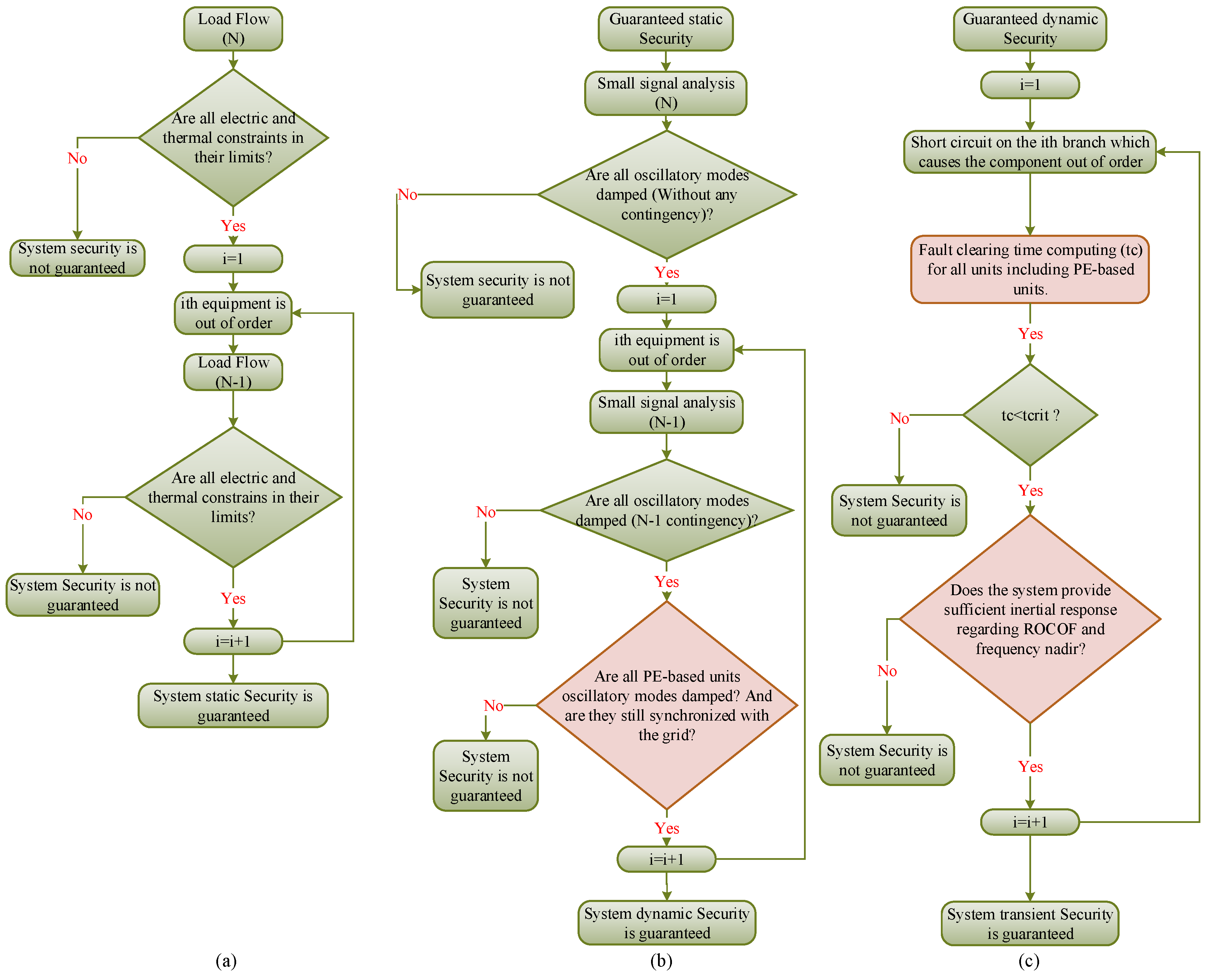
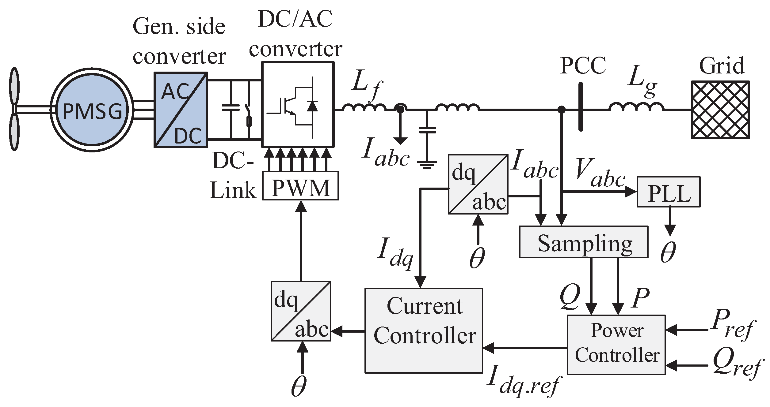
  • To present the static, dynamic, and transient security assessment models of PE-based power systems having high levels of wind turbine penetration with the grid-feeding control mode. For each level of security assessment, e.g., static, dynamic, and transient security assessments, an appropriate model of PE-based units is needed.
The rest of the paper is organized as follows: in Section 2, the security assessments of the conventional power systems are discussed. Section 3 investigates the power system’s security challenges introduced by the PE-based units. Here, some major real-world events are presented and discussed. The proposed guideline used for the security assessment of the system is introduced at the same part. The effectiveness of the proposed guideline for different levels of studies, such as static, dynamic, and transient security, is verified using the simulation results in Section 4. Section 5 concludes this paper.

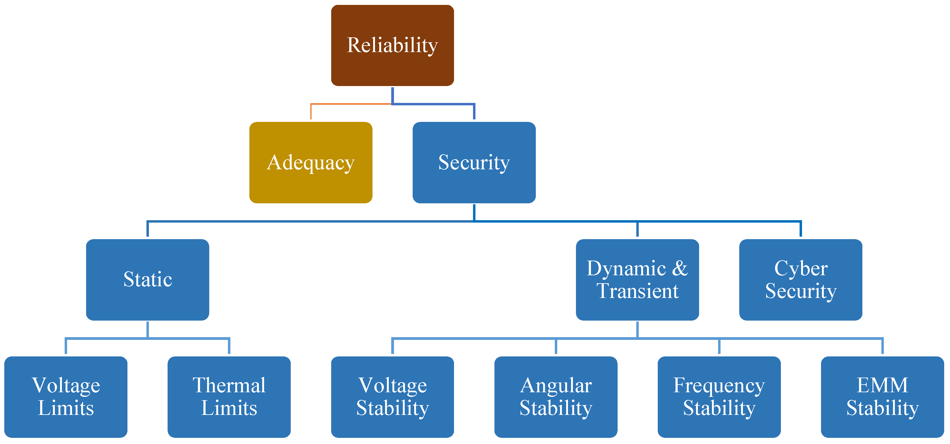
2. Conventional Power System Security Assessment

A power system’s reliability is defined as its ability to cope with its demand and withstand any outage and contingency [26,35]. It is generally divided into two categories, including adequacy and security, as shown in Figure 2 [19,35]. Adequacy measure represents the ability of a power system to cope with its demand at all times, considering planned and unplanned outages and uncertainties [36]. The system adequacy is associated with the planning of power systems for long-term facility expansion, short-term marketing, and operational planning, including unit commitment and economic dispatch among available generation systems. Meanwhile, the system is subjected to different kinds of uncertainties within its operations, which may have planned or unplanned sources. It is worth mentioning that the power system security becomes a more challenging issue when information and communication technology (ICT) is counted in the security assessment [37].
The planned outage can be due to the maintenance of sub-systems and components. Moreover, the unplanned uncertainties can be induced by generation-demand unbalance, load forecasting, renewable power uncertainty, failure of any component, short-circuiting, large load changes, and so on. The occurrence of any contingency in the system may cause system variables violation. These violations could be thermal overloading of lines, system bus voltage, generator rotor angels, and system frequency. They are associated with the different phenomena in the power system and may disturb the power delivery. Therefore, the system must be able to withstand and/or respond to any sudden contingency to maintain power delivery. This ability is called power system security [10,38].
As can be seen from Figure 2, there is a close relationship between the security and stability concepts. However, there is a slight difference between them. A secure system is the one that is stable for all credible contingencies. However, for the stability of the system, only the current system condition needs to be checked (without any contingency assessment) [10,39].
To guarantee the system security, it is high of importance to examine all likely contingency occurrences through analytical analysis and simulations. Therefore, the system operator should evaluate the different contingency occurrences to understand the system behavior after any outage. The impact of any likely disturbance on the system’s stability and the voltage and thermal limits must be analyzed. For the cases which violate the system’s performance, appropriate corrective and/or preventive actions should be applied to sustain the system’s security. The system’s security assessment is classified into two categories, including static and transient/dynamic security [40].
A static security assessment evaluates the system voltage and the equipment’s thermal limits violations after any contingency to ensure that they remain in acceptable intervals [32,41]. Otherwise, the protection system will separate the components, or it may isolate a part of the system [42,43,44]. However, before entering into the steady state region, the system stability should be assured after a contingency [45]. Following the causes of instabilities, power system stability issues are conventionally classified as voltage stability, angular stability, or frequency stability issues [10,26].
Voltage stability is associated with the ability of a power system to maintain the voltage of all buses after any contingency. Voltage instability may occur once the system controllers and/or operators cannot prevent progressive voltage rise or fall under a disturbance [10,46]. Voltage instability causes loss of load, transmission line outages, loss of generation, and consequently, cascading outages. In the case of widespread voltage instability, voltage collapse may occur, leading to a blackout.
Angular stability is associated with the ability of a power system to maintain the synchronism of the synchronous generators, when it is subjected to a contingency. In the steady state, there is an equilibrium between the mechanical and electro-magnetic torques of turbine-generators, and hence the rotor speed of all generators is constant. Further, the generators are synchronized to be at the same frequency. Any contingency in the system may cause acceleration or deceleration of the rotors in the generators. The relative rotor angles will be changed, and depending on the initial operating state before disturbance and the disturbance severity, the relative rotor angles might be settled in an equilibrium state or become unstable by losing synchronism. Loss of synchronism can occur between a generator and the rest of system, or between two groups of generators.
Frequency stability represents the power system’s ability to maintain the system frequency after a severe disturbance, which causes generation-demand unbalance. Frequency instability may occur in the form of frequency fluctuations, which may trigger the protection devices [47]. Severe contingencies cause large digressions in the system frequency. Controls, protections, and processes will respond to these severe excursions to maintain the system stability. The system stability depends on the appropriate coordination of controls and protection systems, sufficient equipment responses, and adequate primary and secondary reserves. System instability may occur due to lack of adequate reserves, inappropriate under-frequency load-shedding, overspeed controls of turbines, and so on.

2.1. Power System Blackouts-Examples

Most of the power systems all over the world have experienced blackouts. A shortlist of major power outages are listed in Table 1. Some reviews, regarding the history of the power system blackouts, can be found in [48]. Some PE-based power system blackouts are discussed as follows:

2.1.1. South Australia (SA) Blackout September 2016

On 28 September 2016, 52% of wind turbines were lost in SA’s network, due to a severe storm [51]. Consequently, the SA network was separated from the rest of the network. The isolated SA network became a system with a high penetration of wind turbines, which collapsed afterwards. There are a couple of issues which were identified as the main points of the SA network blackout: (a) Over-voltage of two synchronous machines that lead to generation trips. This led the system to have even less inertial support. (b) High rate of change of frequency (ROCOF) (6 Hz/s based on the Australian Energy Market Operator’s report [57]) that probably affected some ROCOF-sensitive protection systems. This led to more generation trips. (c) Under frequency load shedding (UFLS) detected in the system (47.5 Hz).
What can be concluded from the SA network blackout is: power systems with high penetration levels of PE-based units have low inertia, which leads to higher ROCOF and fluctuations in the bus voltage magnitudes.
The other issue worth mentioning is the undesired affect on the protection system from converter-based energy sources, due to an incorrect frequency estimation in some buses. Most often, the frequency is measured by the phase-locked loop (PLL) for a converter-based energy source. However, the PLL is very sensitive to its input magnitude and phase angle. A phase-jump may lead to a wrong estimation of the frequency, and the act of protection system set based on the PLL’s estimated frequency [58].

2.1.2. 1200 MW PV Resource Interruption August 2016

On 16 August 2016, fifteen transmission line faults happened in the Southern California network; four of them lead to loss of solar photovoltaic (PV) generation. In the North American Electric Reliability Cooperation (NERC) report [52], it is mentioned that the PV generation cut because of the wrong frequency detection and in consequence an undesired act of the protection system. Although the system frequency remains constant after the transmission line faults, the inverter PLL detects a frequency drop which is more than 3 Hz. This happens as the PLL transient response is sensitive to its input phase angle and magnitude. A 26 phase-jump during the faults was detected in the system, which led to a wrong frequency estimation by the PLL. Then, the frequency-sensitive protection system acted and disconnected the 1200 MW PV generation from the system.
What can be concluded from the Southern California interruption report is that PE-based generation units should be set in order to avoid an undesired unit tripping. On the other hand, a large loss of generation, such as 1200 MW, may cause a cascading trip, which may lead to system instability.

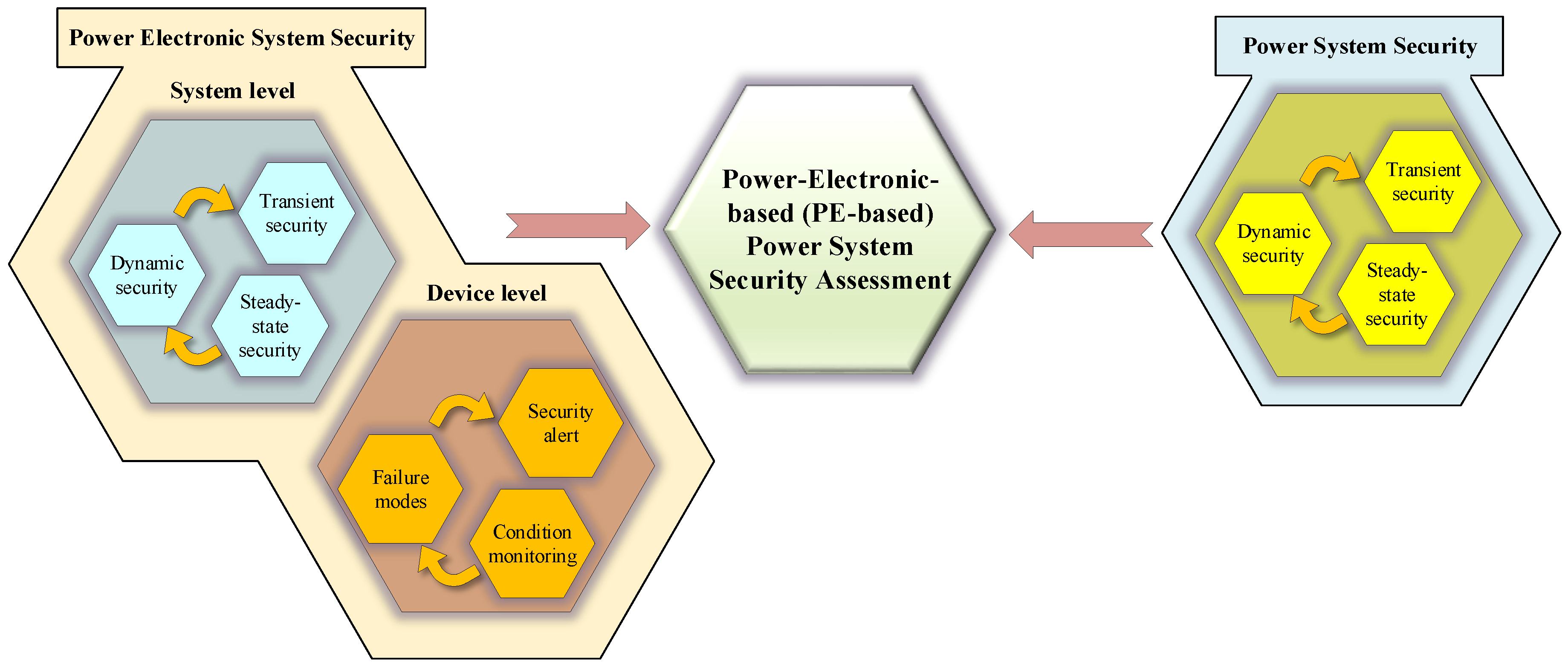
3. Power-Electronic-Based Power System Security

3.1. PE-Based Power System Security Challenges

In this section, the main challenges of power system security caused by the increase of PE-based unit penetration are discussed.
One of the main differences between the conventional energy sources, such as thermal and hydro-power plants, with renewable energy sources (RES), such as wind turbines and PV power plants, is the lack of inertia in the latter one. PE-based energy sources have no rotational part that acts as the inertia source to support the system’s frequency response [59,60]. Therefore, a disturbance that leads to frequency fluctuations in a system with high penetration of PE-based energy sources, may lead to lower frequency nadir response and a higher ROCOF, which consequently may lead to unsynchronization of the generators. This type of instability is related to the frequency stability and also rotor angle stability, in which systems with less inertia are more vulnerable to the large disturbances, such as loss of generation. It is worth mentioning that low-inertia PE-based power systems show higher ROCOF in comparison with the conventional power systems. This is extensively seen in small power systems, such as microgrids [12,61].
On the other hand, the control system of PE-based units is more complex in comparison with the conventional one. Generally, a control system is used to synchronize the PE-based unit with the power system. A standard control system used in the synchronization unit is the phase-locked loop (PLL). The PLL is a nonlinear feedback control loop; its stability is related to its parameters and also to the system configuration. Increasing the number of PE-based units makes the power system weaker, which means that the system states are less controllable. In this case, the PE-based unit connected to the weak grid using the PLL for the synchronization may become unstable. The PLL is sensitive to system fluctuations. Although the voltage phase angle and the frequency are decoupled variables in the system, they are coupled in a standard PLL. Therefore, a phase jump in the system may converge to a wrong estimation of the frequency by the PLL. If a protection system is based on the PLL output signals, then a phase jump may converge to an undesired trip of a PE-based unit [23,58,62].
Besides the voltage, angular, and frequency stabilities, the modern power electronics-based power systems are exposed to electro-mechanical-magnetic (EMM) instabilities due to the interactions of the control and hardware components of converters with electrical, magnetic, or mechanical components of the power systems [11,63,64]. The time of interest for this kind of stability is from microseconds related to the switching frequency of converters up to several milliseconds related to the power sharing control loops. So far, EMM stability has not been considered in the security assessments of power systems; the proliferation of converters will highlight the impact of EMM stability on the overall system performance. More security challenges of the PE-based power systems are listed in Table 2.

3.2. A New Guideline for the PE-Based Power System Security Assessment

In this section, a new guideline to assess the PE-based power system security is proposed. The guideline was developed based on the conventional security assessment with some modifications.
The conventional security assessment is discussed in [32]. The first step in the security assessment of the power system is related to the static security of the system, in which the load flow feasibility and different system constraints are checked for a system with different N-1 (or even N-2) contingencies. At this stage, the system static security will be checked for all contingencies. Then, if the system static security is guaranteed for all contingencies, the dynamic security will be checked for the whole system. The dynamic security of the system is related to the stability of the system, when the system is subjected to a contingency. In this way, regarding the dynamic security of the system, the small-signal model of it concerning different contingencies is assessed. If the system’s small-signal model is stable for different contingencies, then the dynamic security is guaranteed. The last step is to check whether the system’s transient security is guaranteed. To do so, the stability of the system subjected to all credible large disturbances is checked. In a conventional security assessment model, the impact of the PE-based unit on the system security is not included.
Regarding the PE-based power system security assessment, the PE-based units’ security is included in all steps of the conventional model. This is shown in Figure 3. In this way, for the static security of the system, no further efforts are needed in comparison with the conventional method. However, for the dynamic and transient security, the PE-based units’ model should be included in the assessment. This can be done by including the PE-based security in the assessment loop, as shown in Figure 3. In order to execute the security assessment of PE-based power systems based on Figure 3, the PE-based units’ synchronization and the system frequency changes should be checked. For the synchronization of PE-based units, the main outline is to check the performance of the synchronization unit of the PE-based energy source. For instance, if a PLL is used to synchronize the unit with the rest of the system, then it should be able to estimate the PCC phase angle and introduce the system frequency with an appropriate dynamic response [58]. In this way, first, the small-signal model of the grid should be checked, so if all eigenvalues of the small-signal model are in the left half of the imaginary plane, it can be concluded that all the oscillatory modes of the system can be damped. Then, for the transient response, it should be checked whether the synchronization unit can estimate the system frequency with an appropriate dynamic response or not [62]. On the other hand, the frequency nadir and the ROCOF can be checked for the whole system. To do so, an average of the synchronous generators’ rotor speed (in pu) is used to define the system frequency, and based on its response to disturbances, ROCOF and system frequency nadir can be defined [65].
Regarding the dynamic security of the PE-based power systems, the small-signal model of the system should be used for the small-signal stability assessment. In this way, for every N-1 contingency, the system small-signal model is checked as to whether it is stable for all small disturbances. If the system is stable for all small-signal case studies (N-1 contingencies), then the system is dynamically stable.
The same process should be done for the transient stability assessment. If the system is stable for all large disturbances, then its transient security is guaranteed. However, as it is mentioned in the latter section, PE-based units’ control system may be affected by large-disturbances. Therefore, their stability for large disturbances should be checked.

4. Simulation Results

To study the security of PE-based power systems, a modified version of the IEEE 39-bus test system is considered as a benchmark test system [72]. Assume all generators are synchronous machines, as is described in Table 3. All moment of inertia values are rated based on their generators’ rated power. The inertia constant is calculated as H = 1 2 J ω 0 2 S b , where J . ω 0 . 2 π and S b are the inertia gain of the machine and the rated power of it, respectively. For instance, the moment of inertia for G7 equals 3.771 based on 700 MVA. G2 is the reference generator, and G1 presents the equivalent of the interconnection to the rest of the USA and Canada.
The power grid should be able to withstand a loss of a major component in a generation trip [10]. Therefore, in this section, the loss of generator 5 (G5) is considered as the contingency. To assess the impact of the PE-based units on the security of the power system, three case studies are presented. Case study 1 presents a conventional power system without any PE-based energy generation source. Case study 2 includes a wind farm, in which a wind farm is modeled as an aggregation of wind turbines connected in parallel at the same bus. For instance, in order to substitute a 100 MVA synchronous generator with a wind farm, one hundred 1 MVA wind turbines connected at the same bus can be used. In this case study, it is shown that the conventional power system security analysis is still credible. Case study 3 presents a power system with high penetration of wind turbines. In this case study, it is shown that although the system is stable from the point of view of power system operation, due to the low center of inertia of the system, the system may enter into an unstable mode for a generation trip. All simulations are done in DigSILENT PowerFactory.
It should be noticed that, in this study, wind turbines are controlled as the grid-feeding converters [73]. Based on that, it could be replaced with other PE-based energy sources, that are controlled in the same mode, such as photovoltaics. In this way, this study can be extended to the penetration of other types of PE-based units. However, other control modes of converters, such as grid-forming converters, can have different impacts on the system-level stability.

4.1. Case Study 1: Conventional Power Systems

For a loss of generation (G5 at t = 50 s), the system frequency and voltage magnitude at bus 6, 25, and 28 voltage magnitudes of the IEEE 39-bus test system are shown in Figure 4 and Figure 5, respectively. Figure 4 shows that the system frequency is stable after a fault; however, it fluctuates by more than 1.3 Hz. It is worth mentioning that the frequency is returning to its initial value because of the governor response. In order to compensate for the frequency change, a secondary control is needed, which is not considered in this simulation. In this way, the system is stable from the rotor angle stability point of view, as all generators are staying synchronized with the system; however the system frequency stability may be violated, due to the large frequency deviation. Figure 5 shows the voltage magnitudes of some of the buses. It should be noted that the system security depends on how the fluctuations can be tolerated in the system [15]. On the other hand, to complete the security assessment the of the system, the analyses that are shown in Figure 4 and Figure 5 should be redone for all N-1 contingencies (and if it is necessary, they should be repeated for N-2 contingency analysis as well).

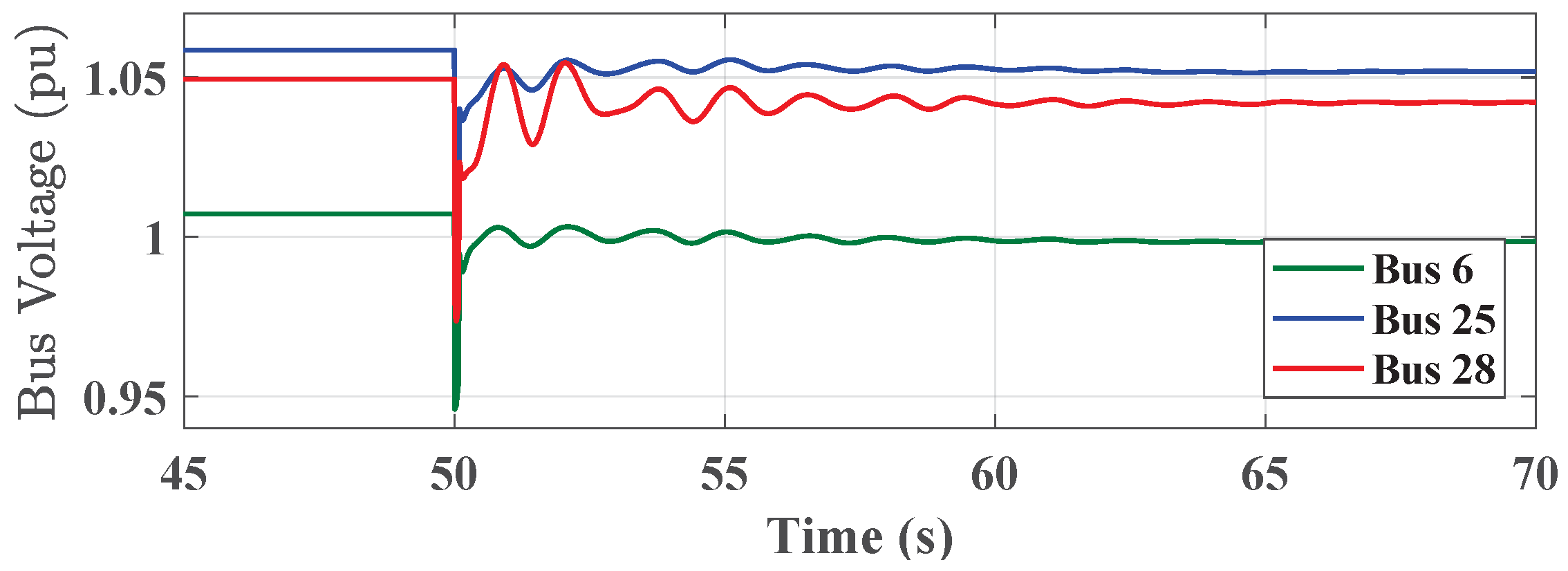
4.2. Case Study 2: PE-Based Power Systems

In this case study, instead of G4, which is a synchronous generator, a wind farm with the same power rating (800 MVA) is used. In this way, wind power penetration is 11.2% (excluding the external generation, G1). The control model of the wind turbine is shown in Figure 6. The wind farm is considered as a parallel combination of the wind turbines.
Considering that G5 trips at t = 50 s, the system stands stable; however, its frequency response becomes worse compared with the conventional method, due to the less inertia of the system. The frequency response of the system is shown in Figure 7. Although Figure 7 is very similar to Figure 4, the frequency nadir is higher in comparison with case study 1. This shows less inertial response in case study 2, due to the higher penetration level of wind turbines.
Bus voltages for some buses are shown in Figure 8. It can be seen that the bus voltages oscillate more than 5%, which may not be desired for the transmission system, and may converge to some protection system actions. It should be noticed that voltage range can be varied from system to system, and acceptable voltage variation range can be defined by the grid codes [74]. Although in this simulation, the protection system actions are not considered, an under-voltage protection system may disconnect a transmission line, and may lead to a cascading failure of the system components.
Like case study 1, it should be noticed that the process of the security analysis should be repeated for all contingencies. If the system is stable for all contingencies, then it can be said that the system is secure.

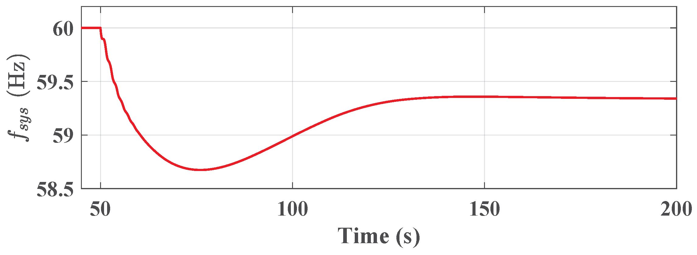
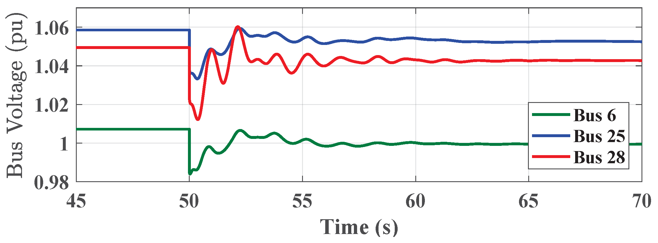
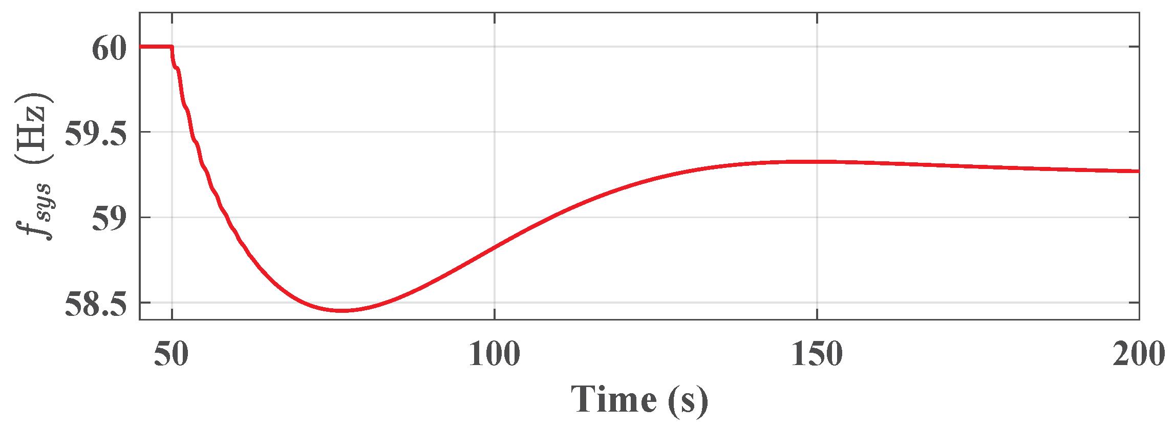
4.3. Case Study 3: PE-Based Power Systems with High Penetration of Wind Power

In this scenario, the penetration of wind power is increased in the system. In this way, generators 3, 4, 6, 7, and 8 (see Table 3) are replaced with wind farms with the same nominal apparent power. In this way, the wind turbine penetration is 43.6% (excluding the external power generation, G1). If G5 trips at t = 50 s, the system will become unstable, as shown in Figure 9 and Figure 10. The system frequency and some bus voltages after the generator trip are shown in Figure 9 and Figure 10, respectively.
Figure 9 shows the average frequency of the system, which is the mean value of synchronous generators’ speed (frequency in Hz) based on their inertia. After the generator trip at t = 50 s, frequency of the system decreases, due to the mismatch of loads and generation. However, at t = 50.3 s some generators become unsynchronized, which leads to instability. This type of instability is referred to the rotor angle instability, which is considered as a transient stability issue. Considering Figure 3c, it is worth mentioning that the system transient security is not guaranteed. As the system is not secure for N contingency analysis, there is not need to further assess the N-1 contingencies, due to the fact that the system cannot maintain its stability without any contingency.
It is worth mentioning that all eigenvalues of the system are on the left-hand-side of the imaginary axis, as shown in Figure 11, which means that the power system is dynamically secure, while its transient stability is not guaranteed; see Figure 3b,c. More specifically, Figure 11 indicates the small-signal stability analysis and does not give any insight into the transient stability assessment. Therefore, while the system can be stable from a small-signal stability point of view (dynamic stability), it might be unstable from a transient stability viewpoint (transient stability).

5. Conclusions

In this paper, a new guideline for the security assessment method of power systems with the penetration of wind turbines is presented. Moreover, the importance of PE-based units in the security and stability of power systems is highlighted. The proposed security assessment guideline includes static, dynamic, and transient security assessments. Based on the proposed model of the security assessment, three case studies are presented to highlight the importance of the PE-based unit penetration on the grid’s stability. It is concluded that the power systems with high penetration levels of converter-based energy sources, such as wind turbines, need more accurate considerations regarding the security and stability of the system. The importance of inertial response and PE-based unit synchronism are assessed in the simulation results. In a case study related to a power system with a high penetration of wind turbines, it is shown that although the grid can be dynamically secure, it may be transiently insecure. In this way, the importance of the proposed security guideline for large-scale power systems is highlighted.
In this paper, only the penetration of wind turbines is considered. However, other converter-based energy sources, such as PE-based energy storage and photovoltaics, may have different impacts on the system security. In addition, HVDC lines may affect system security, due to their voltage and active power control systems, which will be considered in future work.

Author Contributions

Conceptualization, B.S. and S.P.; methodology, B.S., F.B, and C.L.B.; software, B.S. and S.P.; validation, B.S., E.E., and C.L.B.; formal analysis, B.S. and E.E.; investigation, B.S.; Funding acquisition, F.B.; resources, B.S.; data curation, B.S.; writing—original draft preparation, B.S. and S.P.; writing—review and editing, S.P, E.E., F.B, and C.L.B; visualization, B.S.; supervision, F.B.; All authors have read and agreed to the published version of the manuscript.

Funding

This work was supported by the VILLUM FONDEN under the VILLUM Investigators Grant—Reliable Power Electronic Based Power System (REPEPS).

Conflicts of Interest

The authors declare no conflict of interest.

References

  1. Eriksen, P.B.; Ackermann, T.; Abildgaard, H.; Smith, P.; Winter, W.; Garcia, J.R. System operation with high wind penetration. IEEE Power Energy Mag. 2005, 3, 65–74. [Google Scholar] [CrossRef]
  2. Brahma, S.M.; Girgis, A.A. Development of adaptive protection scheme for distribution systems with high penetration of distributed generation. IEEE Trans. Power Deliv. 2004, 19, 56–63. [Google Scholar] [CrossRef]
  3. Blaabjerg, F.; Yang, Y.; Yang, D.; Wang, X. Distributed power-generation systems and protection. Proc. IEEE 2017, 105, 1311–1331. [Google Scholar] [CrossRef] [Green Version]
  4. Magdy, G.; Shabib, G.; Elbaset, A.A.; Mitani, Y. A Novel Coordination Scheme of Virtual Inertia Control and Digital Protection for Microgrid Dynamic Security Considering High Renewable Energy Penetration. IET Renew. Power Gener. 2019, 13, 462–474. [Google Scholar] [CrossRef]
  5. Zhou, M.; Zhai, J.; Li, G.; Ren, J. Distributed dispatch approach for bulk AC/DC hybrid systems with high wind power penetration. IEEE Trans. Power Syst. 2018, 33, 3325–3336. [Google Scholar] [CrossRef]
  6. Blaabjerg, F.; Teodorescu, R.; Liserre, M.; Timbus, A.V. Overview of control and grid synchronization for distributed power generation systems. IEEE Trans. Ind. Electron. 2006, 53, 1398–1409. [Google Scholar] [CrossRef] [Green Version]
  7. Pan, J.; Nuqui, R.; Srivastava, K.; Jonsson, T.; Holmberg, P.; Hafner, Y.J. AC grid with embedded VSC-HVDC for secure and efficient power delivery. In Proceedings of the 2008 IEEE Energy 2030 Conference, Atlanta, GA, USA, 17–18 November 2008; pp. 1–6. [Google Scholar]
  8. Wen, Y.; Chung, C.; Ye, X. Enhancing frequency stability of asynchronous grids interconnected with HVDC links. IEEE Trans. Power Syst. 2017, 33, 1800–1810. [Google Scholar] [CrossRef]
  9. Oliveira, W.D.; Vieira, J.P.; Bezerra, U.H.; Martins, D.A.; das G. Rodrigues, B. Power system security assessment for multiple contingencies using multiway decision tree. Electr. Power Syst. Res. 2017, 148, 264–272. [Google Scholar] [CrossRef]
  10. Kundur, P. Definition and classification of power system stability IEEE/CIGRE joint task force on stability terms and definitions. IEEE Trans. Power Syst. 2004, 19, 1387–1401. [Google Scholar]
  11. Farrokhabadi, M.; Canizares, C.A.; Simpson-Porco, J.W.; Nasr, E.; Fan, L.; Mendoza-Araya, P.; Tonkoski, R.; Tamrakar, U.; Hatziargyriou, N.D.; Lagos, D.; et al. Microgrid Stability Definitions, Analysis, and Examples. IEEE Trans. Power Syst. 2019, 35, 13–29. [Google Scholar] [CrossRef]
  12. Golpîra, H.; Seifi, H.; Messina, A.R.; Haghifam, M. Maximum Penetration Level of Micro-Grids in Large-Scale Power Systems: Frequency Stability Viewpoint. IEEE Trans. Power Syst. 2016, 31, 5163–5171. [Google Scholar] [CrossRef]
  13. Xiong, L.; Li, P.; Wu, F.; Wang, J. Stability Enhancement of Power Systems with High DFIG-Wind Turbine Penetration via Virtual Inertia Planning. IEEE Trans. Power Syst. 2019, 34, 1352–1361. [Google Scholar] [CrossRef]
  14. Teodorescu, R.; Liserre, M.; Rodriguez, P. Grid Converters for Photovoltaic and Wind Power Systems; John Wiley & Sons: Hoboken, NJ, USA, 2011. [Google Scholar]
  15. IEEE Standard for Interconnection and Interoperability of Distributed Energy Resources with Associated Electric Power Systems Interfaces; IEEE Std 1547-2018 (Revision of IEEE Std 1547-2003); IEEE: Piscataway, NJ, USA, 2018; pp. 1–138. [CrossRef]
  16. Abo-Khalil, A.G. Impacts of Wind Farms on Power System Stability. In Modeling and Control Aspects of Wind Power Systems; InTech: London, UK, 2013. [Google Scholar] [CrossRef] [Green Version]
  17. Sourkounis, C.; Tourou, P. Grid Code Requirements for Wind Power Integration in Europe. Conf. Pap. Energy 2013, 2013, 437674. [Google Scholar] [CrossRef] [Green Version]
  18. Vrakopoulou, M.; Margellos, K.; Lygeros, J.; Andersson, G. A Probabilistic Framework for Reserve Scheduling and N-1 Security Assessment of Systems with High Wind Power Penetration. IEEE Trans. Power Syst. 2013, 28, 3885–3896. [Google Scholar] [CrossRef]
  19. Wang, Y.; Vittal, V.; Abdi-Khorsand, M.; Singh, C. Probabilistic Reliability Evaluation Including Adequacy and Dynamic Security Assessment. IEEE Trans. Power Syst. 2020, 35, 551–559. [Google Scholar] [CrossRef]
  20. Zarei, S.F.; Mokhtari, H.; Ghasemi, M.A.; Blaabjerg, F. Reinforcing fault ride through capability of grid forming voltage source converters using an enhanced voltage control scheme. IEEE Trans. Power Deliv. 2018, 34, 1827–1842. [Google Scholar] [CrossRef]
  21. Ebrahimzadeh, E.; Blaabjerg, F.; Wang, X.; Bak, C.L.; Lund, T.; Andersen, G.K.; Suárez, C.G.; Berg, J.J. Small signal modeling of wind farms. In Proceedings of the 2017 IEEE Energy Conversion Congress and Exposition (ECCE), Cincinnati, OH, USA, 1–5 October 2017; pp. 3710–3716. [Google Scholar]
  22. Zhang, L.; Harnefors, L.; Nee, H.P. Power-synchronization control of grid-connected voltage-source converters. IEEE Trans. Power Syst. 2010, 25, 809–820. [Google Scholar] [CrossRef]
  23. Wang, X.; Harnefors, L.; Blaabjerg, F. Unified impedance model of grid-connected voltage-source converters. IEEE Trans. Power Electron. 2018, 33, 1775–1787. [Google Scholar] [CrossRef] [Green Version]
  24. Shakerighadi, B.; Ebrahimzadeh, E.; Blaabjerg, F.; Leth Bak, C. Large-Signal Stability Modeling for the Grid-Connected VSC Based on the Lyapunov Method. Energies 2018, 11, 2533. [Google Scholar] [CrossRef] [Green Version]
  25. Hu, Q.; Fu, L.; Ma, F.; Ji, F. Large Signal Synchronizing Instability of PLL-Based VSC Connected to Weak AC Grid. IEEE Trans. Power Syst. 2019, 34, 3220–3229. [Google Scholar] [CrossRef]
  26. Kundur, P.; Balu, N.J.; Lauby, M.G. Power System Stability and Control; McGraw-hill: New York, NY, USA, 1994; Volume 7. [Google Scholar]
  27. Renedo, J.; Garcı, A.; Rouco, L. Active power control strategies for transient stability enhancement of AC/DC grids with VSC-HVDC multi-terminal systems. IEEE Trans. Power Syst. 2016, 31, 4595–4604. [Google Scholar] [CrossRef]
  28. Zhang, H.-L.; Yao, S.-J.; Peng, Z. Research on small-signal stability of hybrid multi-terminal HVDC system and control system parameter design. J. Eng. 2017, 2017, 2401–2406. [Google Scholar]
  29. Sanchez, S.; Garces, A.; Bergna-Diaz, G.; Tedeschi, E. Dynamics and stability of meshed multiterminal hvdc networks. IEEE Trans. Power Syst. 2018, 34, 1824–1833. [Google Scholar] [CrossRef] [Green Version]
  30. Lu, Y.; Tomsovic, K. Wide Area Hierarchical Voltage Control to Improve Security Margin for Systems with High Wind Penetration. IEEE Trans. Power Syst. 2018, 33, 6218–6228. [Google Scholar] [CrossRef]
  31. Che, L.; Liu, X.; Zhu, X.; Wen, Y.; Li, Z. Intra-Interval Security Based Dispatch for Power Systems with High Wind Penetration. IEEE Trans. Power Syst. 2019, 34, 1243–1255. [Google Scholar] [CrossRef]
  32. Shakerighadi, B.; Peyghami, S.; Ebrahimzadeh, E.; Blaabjerg, F.; Bak, C.L. Security Analysis of Power Electronic-based Power Systems. In Proceedings of the IECON 2019—45th Annual Conference of the IEEE Industrial Electronics Society, Lisbon, Portugal, 14–17 October 2019; Volume 1, pp. 4933–4937. [Google Scholar] [CrossRef]
  33. Bie, Z.; Lin, Y.; Li, G.; Li, F. Battling the Extreme: A Study on the Power System Resilience. Proc. IEEE 2017, 105, 1253–1266. [Google Scholar] [CrossRef]
  34. Moore, L.M.; Post, H.N. Five years of operating experience at a large, utility-scale photovoltaic generating plant. Prog. Photovolt. Res. Appl. 2008, 16, 249–259. [Google Scholar] [CrossRef]
  35. Peyghami, S.; Pakensky, P.; Blaabjerg, F. An overview on the Reliability of Modern Power Electronic Based Power Systems. IEEE Open J. Power Electron. 2020, 1, 34–50. [Google Scholar] [CrossRef] [Green Version]
  36. Billington, R.; Allan, R.N. Reliability Evaluation of Power Systems, 2nd ed.; Plenum: New York, NY, USA, 1994. [Google Scholar]
  37. Aravinthan, V.; Balachandran, T.; Ben-Idris, M.; Fei, W.; Heidari-Kapourchali, M.; Hettiarachchige-Don, A.; Jiang, J.N.; Lei, H.; Liu, C.; Mitra, J.; et al. Reliability Modeling Considerations for Emerging Cyber-Physical Power Systems. In Proceedings of the 2018 IEEE International Conference on Probabilistic Methods Applied to Power Systems (PMAPS), Boise, ID, USA, 24–28 June 2018; pp. 1–7. [Google Scholar] [CrossRef] [Green Version]
  38. Olivares, D.E.; Mehrizi-Sani, A.; Etemadi, A.H.; Cañizares, C.A.; Iravani, R.; Kazerani, M.; Hajimiragha, A.H.; Gomis-Bellmunt, O.; Saeedifard, M.; Palma-Behnke, R.; et al. Trends in microgrid control. IEEE Trans. Smart Grid 2014, 5, 1905–1919. [Google Scholar] [CrossRef]
  39. Li, Y.; Li, Y.; Sun, Y. Online Static Security Assessment of Power Systems Based on Lasso Algorithm. Appl. Sci. 2018, 8, 1442. [Google Scholar] [CrossRef] [Green Version]
  40. Sterpu, S.; Lu, W.; Besanger, Y.; HadjSaid, N. Power systems security analysis. In Proceedings of the 2006 IEEE Power Engineering Society General Meeting, Montreal, QC, Canada, 18–22 June 2006; p. 5. [Google Scholar] [CrossRef]
  41. Saadun, N.; Sheikh Kamar Sheikh Abdullah, I.D.; Khairun Nizam Mohd Sarmin, M.; Azmi, M.T.; Nadia Nor Khairul Azha, N.; Nik Yusuf, N.S. Advanced Real-Time Power System Analytic Based on Thermal Security under N-1 Contingency. In Proceedings of the 2019 IEEE International Conference on Automatic Control and Intelligent Systems (I2CACIS), Selangor, Malaysia, 29 June 2019; pp. 216–220. [Google Scholar] [CrossRef]
  42. Lu, Z.; He, L.; Zhang, D.; Zhao, B.; Zhang, J.; Zhao, H. A Security Level Classification Method for Power Systems under N-1 Contingency. Energies 2017, 10, 2055. [Google Scholar] [CrossRef] [Green Version]
  43. Ding, T.; Guo, Q.; Bo, R.; Sun, H.; Zhang, B.; Huang, T. A Static Voltage Security Region for Centralized Wind Power Integration—Part II: Applications. Energies 2014, 7, 444–461. [Google Scholar] [CrossRef] [Green Version]
  44. Arava, V.N.; Vanfretti, L. Analyzing the Static Security Functions of a Power System Dynamic Security Assessment Toolbox. Int. J. Electr. Power Energy Syst. 2018, 101, 323–330. [Google Scholar] [CrossRef]
  45. Da Silva, J.M.; Costa, I.; dos Santos, J.V.C.; Barbosa, J.L.V.; Braun, T.; Pessin, G. Toward a More Reliable System for Contingency Selection in Static Security Analysis of Electric Power Systems. IEEE Syst. J. 2020, 14, 1183–1194. [Google Scholar] [CrossRef]
  46. Alimi, O.A.; Ouahada, K.; Abu-Mahfouz, A.M. Real Time Security Assessment of the Power System Using a Hybrid Support Vector Machine and Multilayer Perceptron Neural Network Algorithms. Sustainability 2019, 11, 3586. [Google Scholar] [CrossRef] [Green Version]
  47. Wang, Q.; Bo, Z.; Zhao, Y.; Ma, X.; Zhang, M.; Zheng, H.; Wang, L. Integrated wide area protection and control for power grid security. CSEE J. Power Energy Syst. 2019, 5, 206–214. [Google Scholar] [CrossRef]
  48. Haes Alhelou, H.; Hamedani-Golshan, M.E.; Njenda, T.C.; Siano, P. A survey on power system blackout and cascading events: Research motivations and challenges. Energies 2019, 12, 682. [Google Scholar] [CrossRef] [Green Version]
  49. Romero, J.J. Blackouts illuminate India’s power problems. IEEE Spectr. 2012, 49, 11–12. [Google Scholar] [CrossRef]
  50. Kabir, M.A.; Sajeeb, M.M.H.; Chowdhury, S.M.S.M.; Chowdhury, A.H. Analysis of real time frequency transients and inertia estimation of Bangladesh power system. In Proceedings of the 2015 18th International Conference on Computer and Information Technology (ICCIT), Dhaka, Bangladesh, 21–23 December 2015; pp. 116–121. [Google Scholar] [CrossRef]
  51. Yan, R.; Masood, N.; Kumar Saha, T.; Bai, F.; Gu, H. The Anatomy of the 2016 South Australia Blackout: A Catastrophic Event in a High Renewable Network. IEEE Trans. Power Syst. 2018, 33, 5374–5388. [Google Scholar] [CrossRef]
  52. NERC/WECC Inverter Task Force. 1200 MW Fault Induced Solar Photovoltaic Resource Interruption Disturbance Report: Southern California 8/16/2016 Event; Technical Report; NERC: Atlanta, GA, USA, 2017. [Google Scholar]
  53. Dobson, I.; Newman, D.E. Cascading blackout overall structure and some implications for sampling and mitigation. Int. J. Electr. Power Energy Syst. 2017, 86, 29–32. [Google Scholar] [CrossRef] [Green Version]
  54. Eaton, B.T. United States Annual Report 2013. Technical Report. 2013. Available online: http://powerquality.eaton.com (accessed on 29 April 2020).
  55. Gawanmeh, A.; Alomari, A. Taxonomy Analysis of Security Aspects in Cyber Physical Systems Applications. In Proceedings of the 2018 IEEE International Conference on Communications Workshops (ICC Workshops), Kansas City, MO, USA, 20–24 May 2018; pp. 1–6. [Google Scholar] [CrossRef]
  56. Nagpal, M.; Martinich, T.G.; Jiao, Z.; Manuel, S.; Zhang, H.A.; Alimardani, A. Lessons Learned from a Regional System Blackout and Restoration in BC Hydro. IEEE Trans. Power Deliv. 2018, 33, 1954–1961. [Google Scholar] [CrossRef]
  57. Operator, Australian Energy Market Black system south australia 28 september 2016. In Report of the Australian Energy Market Operator Limited (AEMO); AEMO: Melbourne, Australia, 2017.
  58. Shakerighadi, B.; Ebrahimzadeh, E.; Taul, M.G.; Blaabjerg, F.; Bak, C.L. Modeling and Adaptive Design of the SRF-PLL: Nonlinear Time-Varying Framework. IEEE Access 2020, 8, 28635–28645. [Google Scholar] [CrossRef]
  59. Karimi, A.; Khayat, Y.; Naderi, M.; Dragicevic, T.; Mirzaei, R.; Blaabjerg, F.; Bevrani, H. Inertia Response Improvement in Microgrids: A Fuzzy-Based Virtual Synchronous Generator Control. IEEE Trans. Power Electron. 2019, 35, 4321–4331. [Google Scholar] [CrossRef]
  60. Shakerighadi, B.; Ebrahimzadeh, E.; Blaabjerg, F.; Bak, C.L. Large Signal Stability Assessment of the Grid-Connected Converters based on its Inertia. In Proceedings of the 2019 21st European Conference on Power Electronics and Applications (EPE ’19 ECCE Europe), Genova, Italy, 3–5 September 2019; pp. 1–7. [Google Scholar] [CrossRef]
  61. Golpîra, H.; Messina, A.R. A Center-of-Gravity-Based Approach to Estimate Slow Power and Frequency Variations. IEEE Trans. Power Syst. 2018, 33, 1026–1035. [Google Scholar] [CrossRef]
  62. Karimi Ghartemani, M.; Khajehoddin, S.A.; Jain, P.K.; Bakhshai, A. Problems of Startup and Phase Jumps in PLL Systems. IEEE Trans. Power Electron. 2012, 27, 1830–1838. [Google Scholar] [CrossRef]
  63. Wang, X.; Blaabjerg, F. Harmonic Stability in Power Electronic-Based Power Systems: Concept, Modeling, and Analysis. IEEE Trans. Smart Grid 2018, 10, 2858–2870. [Google Scholar] [CrossRef] [Green Version]
  64. Xia, S.; Zhang, Q.; Hussain, S.; Hong, B.; Zou, W. Impacts of Integration of Wind Farms on Power System Transient Stability. Appl. Sci. 2018, 8, 1289. [Google Scholar] [CrossRef] [Green Version]
  65. Mauricio, J.M.; Leon, A.E. Improving Small-Signal Stability of Power Systems with Significant Converter-Interfaced Generation. IEEE Trans. Power Syst. 2020. [Google Scholar] [CrossRef] [Green Version]
  66. Meng, L.; Zafar, J.; Khadem, S.K.; Collinson, A.; Murchie, K.C.; Coffele, F.; Burt, G.M. Fast Frequency Response From Energy Storage Systems—A Review of Grid Standards, Projects and Technical Issues. IEEE Trans. Smart Grid 2020, 11, 1566–1581. [Google Scholar] [CrossRef] [Green Version]
  67. Ebrahimzadeh, E.; Blaabjerg, F.; Wang, X.; Bak, C.L. Harmonic Stability and Resonance Analysis in Large PMSG-Based Wind Power Plants. IEEE Trans. Sustain. Energy 2018, 9, 12–23. [Google Scholar] [CrossRef]
  68. Ma, S.; Geng, H.; Liu, L.; Yang, G.; Pal, B.C. Grid-Synchronization Stability Improvement of Large Scale Wind Farm During Severe Grid Fault. IEEE Trans. Power Syst. 2018, 33, 216–226. [Google Scholar] [CrossRef] [Green Version]
  69. Huang, L.; Xin, H.; Wang, Z.; Zhang, L.; Wu, K.; Hu, J. Transient Stability Analysis and Control Design of Droop-Controlled Voltage Source Converters Considering Current Limitation. IEEE Trans. Smart Grid 2019, 10, 578–591. [Google Scholar] [CrossRef]
  70. Bae, Y.; Vu, T.; Kim, R. Implemental Control Strategy for Grid Stabilization of Grid-Connected PV System Based on German Grid Code in Symmetrical Low-to-Medium Voltage Network. IEEE Trans. Energy Convers. 2013, 28, 619–631. [Google Scholar] [CrossRef]
  71. Matevosyan, J.; Badrzadeh, B.; Prevost, T.; Quitmann, E.; Ramasubramanian, D.; Urdal, H.; Achilles, S.; MacDowell, J.; Huang, S.H.; Vital, V.; et al. Grid-Forming Inverters: Are They the Key for High Renewable Penetration? IEEE Power Energy Mag. 2019, 17, 89–98. [Google Scholar] [CrossRef]
  72. Peyghami, S.; Davari, P.; Fotuhi-Firuzabad, M.; Blaabjerg, F. Standard Test Systems for Modern Power System Analysis: An Overview. IEEE Ind. Electron. Mag. 2019, 13, 86–105. [Google Scholar] [CrossRef]
  73. Rocabert, J.; Luna, A.; Blaabjerg, F.; Rodriguez, P. Control of power converters in AC microgrids. IEEE Trans. Power Electron. 2012, 27, 4734–4749. [Google Scholar] [CrossRef]
  74. Ackermann, T. (Ed.) Wind Power in Power Systems; John Wiley & Sons, Ltd.: Hoboken, NJ, USA, 2005. [Google Scholar] [CrossRef]
Figure 1. Overall schematic of the PE-based power system security assessment concept.
Applsci 10 03190 g001
Figure 2. Power system security assessment categories, including both static and dynamic analysis.
Applsci 10 03190 g002
Figure 3. PE-based power system security assessment. (a) Static security assessment, (b) dynamic security assessment, (c) and transient security assessment.
Applsci 10 03190 g003
Figure 4. System frequency response to the G5 trip at t = 50 s (case study 1).
Applsci 10 03190 g004
Figure 5. Bus 6, 25, and 28 voltage magnitude responses to G5 trip at t = 50 s for the conventional power system case study (case study 1).
Applsci 10 03190 g005
Figure 6. Hardware and control model of the wind turbine used in the simulation used for security analysis in case studies 2 and 3.
Applsci 10 03190 g006
Figure 7. The PE-based power system frequency response to the generator 5 trip at t = 50 s for the PE-based power system case study (case study 2).
Applsci 10 03190 g007
Figure 8. Bus 6, 25, and 28 voltage magnitude responses to generator 5 trip at t = 50 s for the PE-based power system case study (case study 2).
Applsci 10 03190 g008
Figure 9. The PE-based power system frequency response to the G5 trip at t = 50 s for the system with high penetration of wind turbine (case study 3).
Applsci 10 03190 g009
Figure 10. Bus 6, 25, and 28 voltage magnitude responses to G5 trip at t = 50 s for the system with a high penetration of wind turbine (case study 3).
Applsci 10 03190 g010
Figure 11. Eigenvalue analysis of IEEE 39-bus test system with high wind turbine penetration (case study 3).
Applsci 10 03190 g011
Table 1. Major blackouts in modern power systems with substantial power-electronic-based (PE-based) units.
LocationDateDuration (h)Affected People (million)Causes
India [49]July 201215620Transmission line overload
Bangladesh [50]November 201424150HVDC station outage
South Australia [51]September 201661.7Transmission line outage and cascading events
The US [52]August 201661.7Transmission line outage and cascading events
The US [53]March 20171121Transmission line outage and cascading events
The US [54]September 201757.6Transmission line trip
Brazil [55]March 2018110Transmission line trip
Canada [56]December 201840.6Wind reached speed of 100 km/h
Table 2. PE-based power system security challenges.
PE-based Power System Security ChallengesContingencies derived by PE-based units’ designSystem frequency supportLack of inertia/high ROCOF [65]
Fast frequency response limitations [66]
Small-signal stabilityHarmonic stability & Oscillations [67]
Grid-tied VSC synchronization [68]
Undesired contingenciesGrid codes requirementVSC’s current limitations [69]
Grid codes for the VSC’s fault ride through [70]
Synchronization challengesWrong frequency estimation & PLL transient response [58,62]
Lack of standardization [71]
Table 3. IEEE 39-bus test system synchronous generator data.
Generator NumberNominal Power [MVA]Moment of Inertia [s]
G1 (Genetator connected to Bus 39)100005
G2 (Genetator connected to Bus 31)7004.329
G3 (Genetator connected to Bus 32)8004.475
G4 (Genetator connected to Bus 33)8003.575
G5 (Genetator connected to Bus 34)3004.333
G6 (Genetator connected to Bus 35)8004.35
G7 (Genetator connected to Bus 36)7003.771
G8 (Genetator connected to Bus 37)10003.471
G9 (Genetator connected to Bus 38)10003.45
G10 (Genetator connected to Bus 30)10004.2

