Case Report

Immediate Implant Placement and Provisionalization in the Esthetic Zone Revisited: The Marginal Migration Concept (MMC)

by
Konstantinos Valavanis
1,2,*,
Ioannis Vergoullis
3,4,
Michalis Papastamos
5 and
Henry Salama
6,7
1
Oral Surgery Department, University of Naples Federico II, 80138 Napoli, Italy
2
Private Practice, 15123 Athens, Greece
3
Periodontics Department, School of Dentistry, Louisiana State University, New Orleans, LA 70119, USA
4
Private Practice, 85100 Rhodes, Greece
5
Private Dental Lab, 17343 Athens, Greece
6
School of Dental Medicine, University of Pennsylvania, Philadelphia, PA 19104, USA
7
Private Practice, Atlanta, GA 30339, USA
*
Author to whom correspondence should be addressed.
Appl. Sci. 2020, 10(24), 8944; https://doi.org/10.3390/app10248944
Submission received: 22 November 2020 / Revised: 9 December 2020 / Accepted: 10 December 2020 / Published: 15 December 2020
(This article belongs to the Special Issue Material Science, Implants, and Peri-Implant Tissues)

Abstract

:
Immediate implant placement and provisionalization in the esthetic zone is a desirable approach that presents several advantages but at the same time embosses several risk factors that can lead to severe esthetic complications. The purpose of this article was to propose a new protocol that could allow for the maintenance and even the improvement of the hard and soft tissue topography, leading to superior esthetic results. The proposed protocol, when certain criteria are met, could be applied even for cases where the extraction socket morphology is currently proposed as a contra-indication for immediate implant placement and provisionalization.

1. Introduction

Immediate implant placement and provisionalization at the time of extraction in the esthetic zone is today a common treatment modality [1]. The literature outlines the non-interventionist healing process of a post-extraction socket, or in combination with a socket preservation technique, including bone and/or soft tissue grafting, as well as with or without simultaneous implant placement [2,3,4,5,6,7]. While many protocols have been suggested to achieve the establishment of an esthetic and natural result post extraction in the anterior region, challenges persist [8,9,10]. Primary among the challenges faced by clinicians are predictability and reproducibility of esthetic outcomes. Especially, as they relate to the volumetric changes that occur to the labial plate of the socket housing post-extraction, both in the bucco-lingual and apico-coronal aspect. These volumetric osseous changes in turn often result in labial gingival recession, as well as negative optical manifestations of the soft tissue due to concavities. Studies have also shown successful results in intact type I sockets, ideal bone and soft tissue profiles (Salama and Salama 1993) at onset, utilizing a combination of bone replacement graft (BRG) and a temporary prosthesis at the time of extraction and implant placement [11,12,13]. In addition, simultaneous connective tissue grafting grafting in order to increase the stability and predictability of an esthetic outcome have also been suggested [14,15]. Furthermore, there is also evidence that in type I, the labial root fragment can be maintained to biologically stabilize the labial osseous and soft tissue (Partial extraction therapy) [16,17]. However, most immediate implant treatment protocols specifically address only type I sockets, where no hard or soft tissue deficiencies exist prior to extraction [18,19].
Through two case reports, the purpose of this article is to present a new esthetic zone protocol for immediate placement and provisionalized of implants in both class I sockets, as well as class II sockets with a Miller Class I recession deficiencies. Novel steps are introduced and existing clinical protocols are modified, for both the surgical and restorative interventions, with the goal of predictably achieving an optimal result utilizing simpler and less invasive therapeutic protocols 18, including the step-by-step description and application of the Marginal Migration Concept (MMC) in a Class II site [18].

2. Case 1

2.1. “Report and Protocol”

A 40-year-old male presented in the clinic of one of the authors (K.V.) in order to replace a hopeless upper right central incisor. The patient was non-smoker, with a clear medical history, no active dental disease, and no contra-indications present for implant therapy [20]. After clinical and radiographic evaluation, the site was classified as a socket class I, with thin soft tissue biotype and marginal soft tissue apical mislocation at the mid-buccal area (Figure 1, Figure 2 and Figure 3) [18]. The marginal migration concept protocol of treatment (MMC) was selected as suitable for this case. The proposed treatment protocol was thoroughly explained to the patient along with any alternative treatment options. The requirements of the Helsinki Declaration were observed, and the patient gave informed consent for all surgical and restorative procedures.

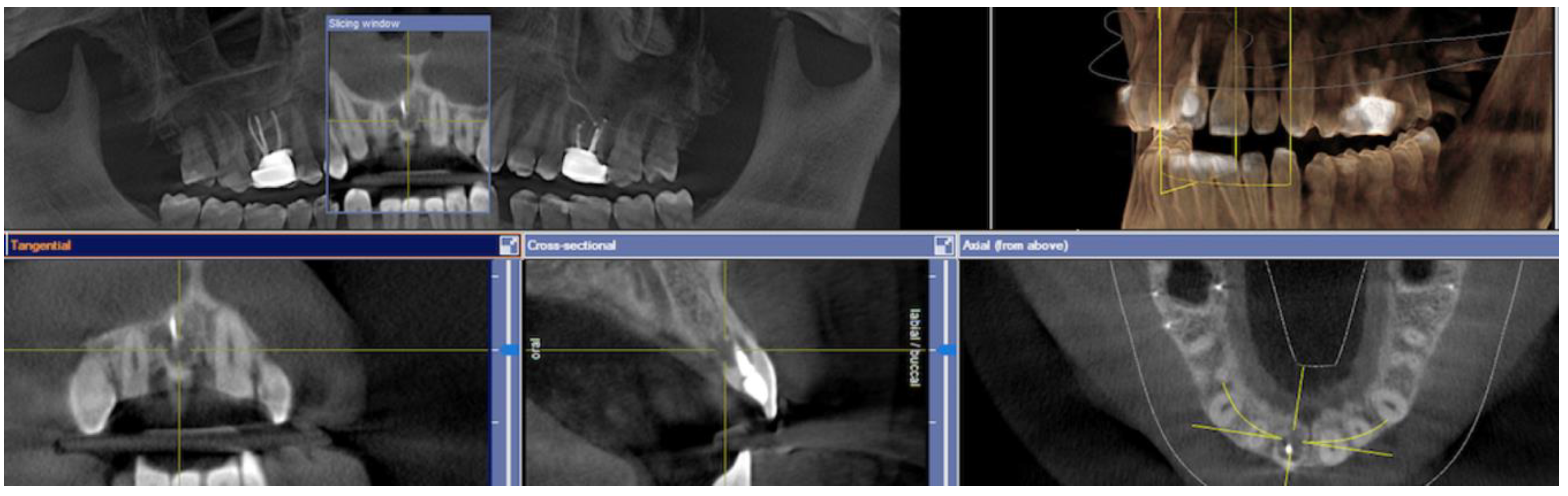
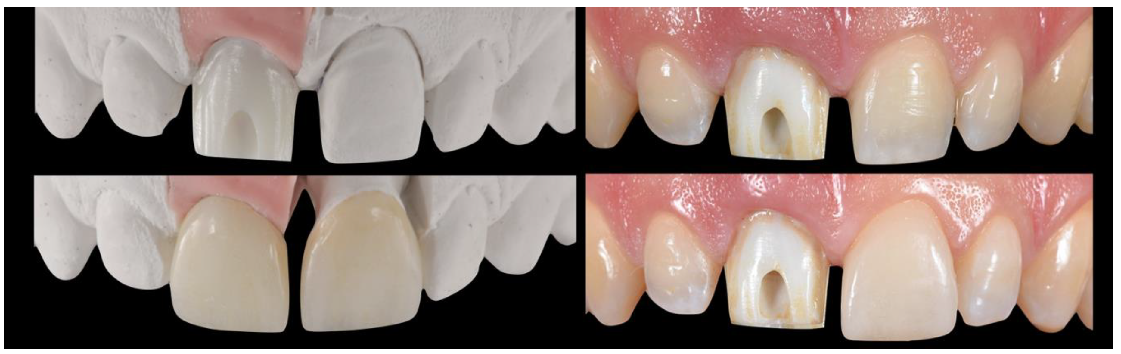
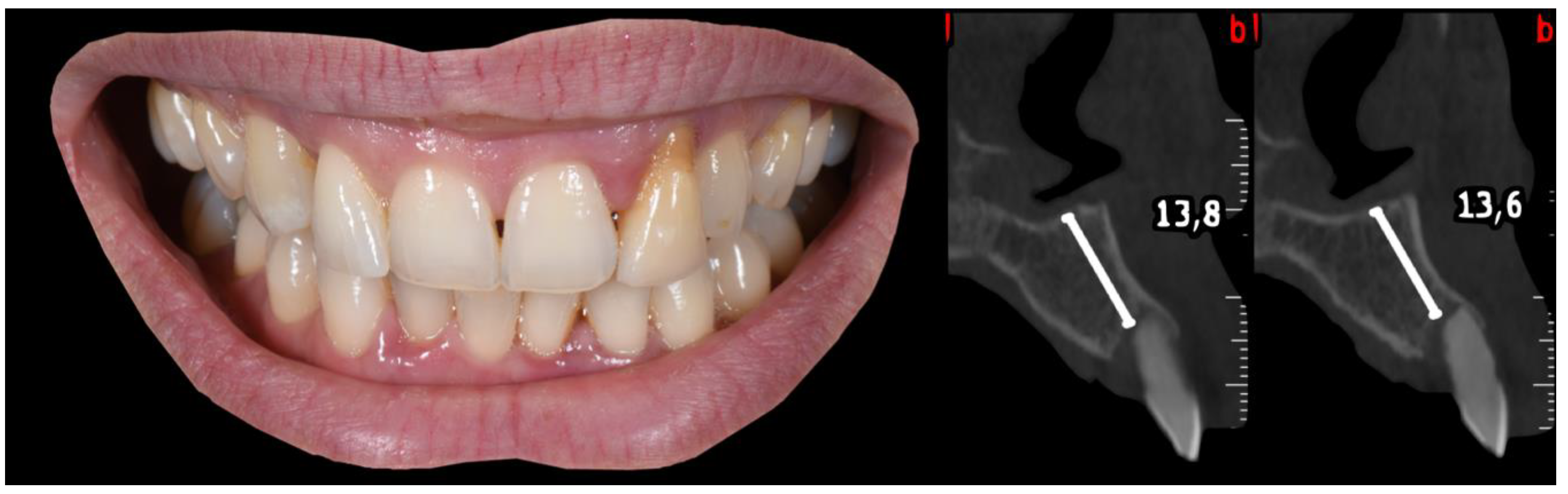
2.2. Pre-Surgical Stage
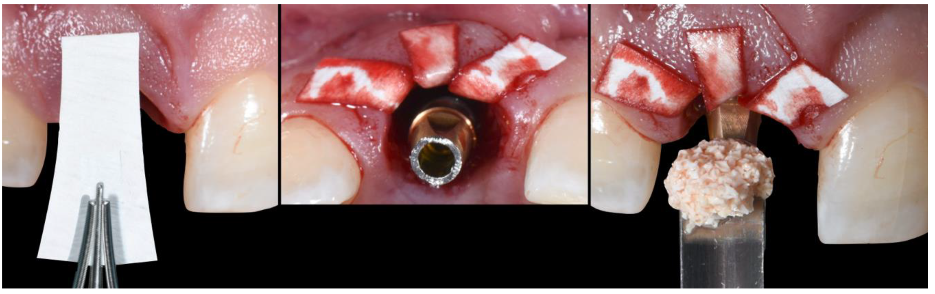
First, the initial impressions were taken. Then a diagnostic wax up was performed if necessary and a silicone index was fabricated to be used for the fabrication of the temporary prosthesis at the time of surgery (Figure 1). Alternatively, a prefabricated temporary cell could be used for the same purpose.

2.3. Surgical Stage

The patient received 1 gr of amoxicillin one hour prior to surgery. At the time of surgery, he rinsed for 1 min with chlorhexidine solution 0.12% (Froiplak, Froika, Greece) and the area of interest was anesthetized locally with articaine 4%, epi 1:200k (Septanest, Greece).
Step 1.
A flap-less extraction was performed, taking care to prevent any damage to the soft and hard tissue (Scheme 1A, Figure 4) [21].
(A)
Extraction socket presentation, where the red line represents the supra-periosteal pouch flap.
(B)
Three-dimensional implant positioning, where different locations of the implant axis can achieve the desired location of the platform and neck of the implant.
(C)
Fits abutment selection, where the shoulder is located 0.5 mm apically to the cervical gingival margin.
(D)
Membrane adaptation, being in contact with the internal wall of the socket.
(E)
Bone replacement graft BRG introduction into the available space present within the socket, occupying both the soft and hard tissue zones present below the abutment’s shoulder.
(F)
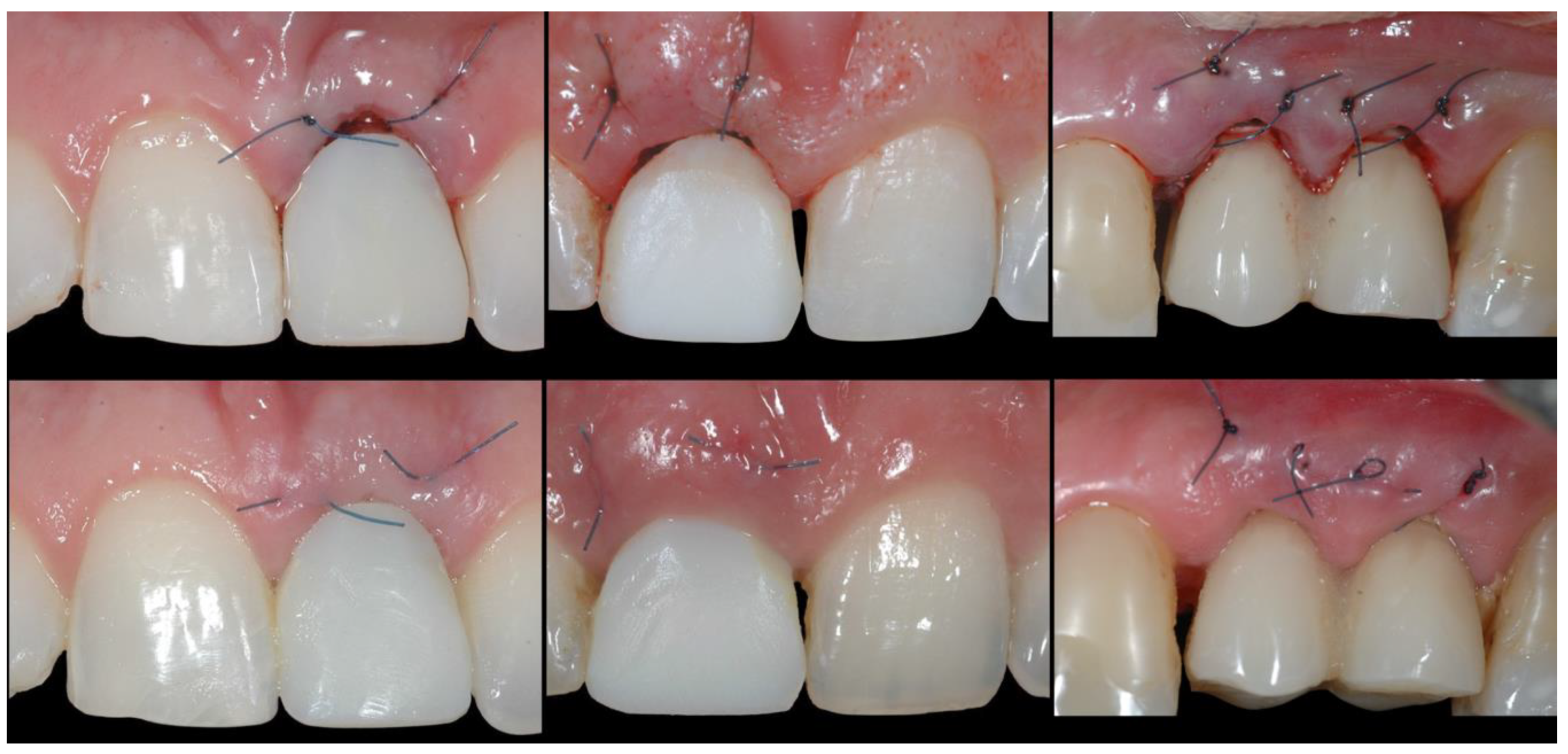
Membrane adaptation and suturing with vertical mattress sutures.
(G)
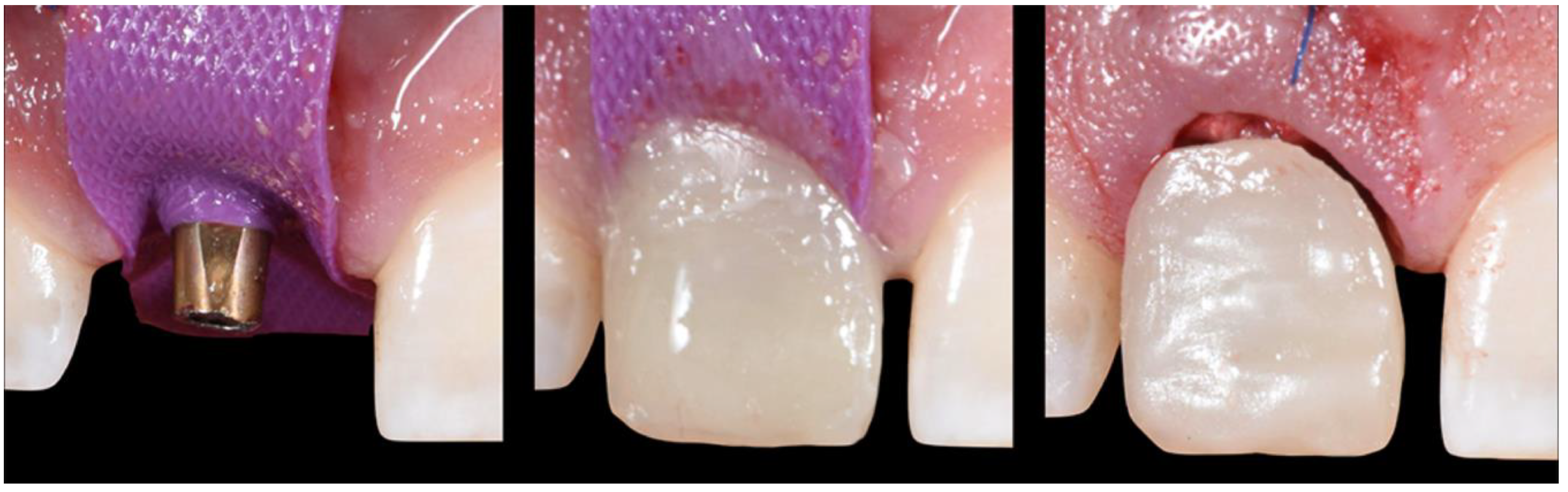
Temporary prosthesis delivery, where the cervical margin is located supra-gingivally and comprises a 90′ emergence angle in relation to the abutment.
Step 2.
A partial thickness, supra-periosteal, trapezoidal-shaped pouch with a suitable blade on the buccal aspect only was created, without involving the adjacent papillae. The pouch was extended apically, further than the mucogingival junction, and laterally at least one root mesio-distally, in order to increase the lateral dimensions of the base of the pouch and adequately mobilize the facial tissue. (Scheme 1B and Scheme 2A, Figure 4)
(A)
Supra-periosteal pouch design, demonstrating proper lateral and vertical extensions. The red lines demonstrate the pouch, while the yellow line demonstrates the mucogingival junction.
(B)
First abutment in place and membrane adaptation prior to BRG introduction.
(C)
Final relationship between first temporary prosthesis, abutment, and cervical gingival tissue.
Step 3.
The osteotomy as per the implant manufacturer’s recommendation was generated and a narrow diameter implant was placed, which preferably comprised a stable conical connection and platform switching features (Anyridge, Megagen, South Korea) [22]. The implant had to be placed in a way that the platform and neck of the implant body presented at least 2 mm horizontal distance from the coronal part of the buccal plate. With regards to depth, the position the implant platform had to be at least 3 mm apical to the zenith of the future prosthesis [16,23,24,25]. (Scheme 1B, Figure 5).
Step 4.
The implant was connected to a temporary abutment comprising a shoulder with tulip shape and lateral dimensions that restrict it from being in touch with the buccal soft tissue [26]. The height of the shoulder had to be such that would allow its coronal margin to be located 0.5 mm apical to the existing free gingival margin. (Scheme 1C, Figure 5)
Step 5.
A resorbable membrane was utilized that could maintain its function for at least 12 weeks (Jason, Botiss, Germany), after properly trimming it, to adequately fit the lateral dimensions of the buccal side of the socket [27]. The membrane was placed within the socket, being in contact with the internal wall of the buccal plate (socket type I) and/or the periosteum in case the buccal plate was partially or completely absent (socket type II). The coronal part of the membrane was to be extending coronally to the free gingival margin, providing a “supra-socket” portion. Two vertical cuts were performed to the supra-socket portion of the membrane only, so that the latter was separated in approximately three equal parts. (Scheme 1D and Scheme 2B, Figure 6).
Step 6.
A slowly absorbable BRG material was introduced, e.g., xenograft (Bioss, Geistlich, Swtzerland), within the socket in order to fill any gaps present around the implant body and the abutment shoulder [28]. The BRG had to fill all spaces in both the hard tissue and soft tissue zone, while not extending above the coronal margin of the shoulder that would receive the prosthesis. Following, the supra-socket parts of the membrane were folded inwards on top of the BRG and around the abutment, without applying any tension (Scheme 1E, Figure 6 and Figure 7).
Step 7.
Two vertical mattress sutures were placed in a bucco-lingual direction; one at the mesial and one at the distal line angle of the socket, making sure that the coronal border of the suture was located at least 3 mm apical to the free gingival margin, at the buccal aspect of the site. In addition, the distance between the suture’s coronal and apical points on the buccal site had to be smaller than the one of palatal side (Scheme 1F and Scheme 2C, Figure 8). These sutures would now apply a coronal pull force to the tissue, while at the same time providing lateral borders aiming to constrain the blood clot present underneath the supra-periosteal buccal flap from migrating laterally to the site.
Step 8. (Provisional restoration)
A trapezoidal shape piece of sterile rubber dam was installed around the pillar of the temporary abutment, making sure it fully covered the sutures (Figure 9).
Step 9.
The area of interest of the silicone index, which was pre-surgically fabricated, was filled with suitable acrylic resin material and properly installed in the patient’s arch. The material was allowed to set and then the silicone index was removed from the mouth and subsequently the provisional restoration from the silicone index was removed [29]. The same process could be applied with the use of a prefabricated temporary cell instead of the index.
Step 10.
The prosthesis was modified by adding or removing acrylic resin material, so that its cervical portion comprised a straight line with 90′ emergence angle. This cervical portion had to be located at least 1 mm supra-gingivally once connected with the implant, leaving adequate space for the soft tissue to migrate coronally (Scheme 1G and Scheme 2C, Figure 10).
Step 11.
The provisional restoration was cemented, supra-gingivally, on the temporary abutment with a suitable permanent cement and any necessary occlusal adjustments were performed so that the prosthesis was out of contact in occlusion, protrusion, and lateral excursions [30] (Figure 10).
Step 12.
The patient was provided with all necessary post-operative instructions and medication as per standard of care for immediately-loaded implant cases. (Soft diet for 6 weeks, oral hygiene instructions, Ibuprofen 600 mg TID for four days and then as needed) [31].
Step 13.
The patient was re-evaluated at 10 days and the sutures were removed (Figure 11).
Step 14.
The patient was re-evaluated at 4 weeks and at 3 months to ensure proper healing (Figure 12).

2.4. Transitional Restoration Stage

After proper healing time for the completion of the osseointegration process passed (3 months for the presented case), the clinical evaluation of the site revealed a successful migration of the facial soft tissue in a coronal location (Figure 13).
At this stage, the first provisional restoration needed to be removed and be replaced by a second provisional/transitional restoration [32]. The goal for the transitional restoration was to condition the peri-implant soft tissue to the desired architecture and allow it to mature in this final shape [8,33,34] (Figure 13).
Step 1.
The provisional restoration was removed and the implant was evaluated clinically and radiographically for successful osseointegration [35] (Figure 13).
Step 2.
A new temporary abutment was installed onto the implant, which comprised a shoulder of the same shape and lateral dimensions, as per the first temporary abutment used in the previous stage. However, the margin of the second temporary abutment had to be located 0.5 mm below the zenith margin of the future prosthesis, irrespectively of the location of the existing free gingival margin (Figure 14).
Step 3.
The cervical contouring concept was utilized in order to modify the cervical and sub-gingival portion of the transitional temporary prosthesis [8]. More specifically, the crown portion of the transitional prosthesis along with its cervical margin now comprised dimensions equal to the ones of the contra-lateral tooth (exact replica). The transitional prosthesis was installed onto the implant as one piece with the new temporary abutment (screw-cemented), or in two pieces (cemented), applying lateral pressure to the soft tissue (Figure 15 and Figure 16).

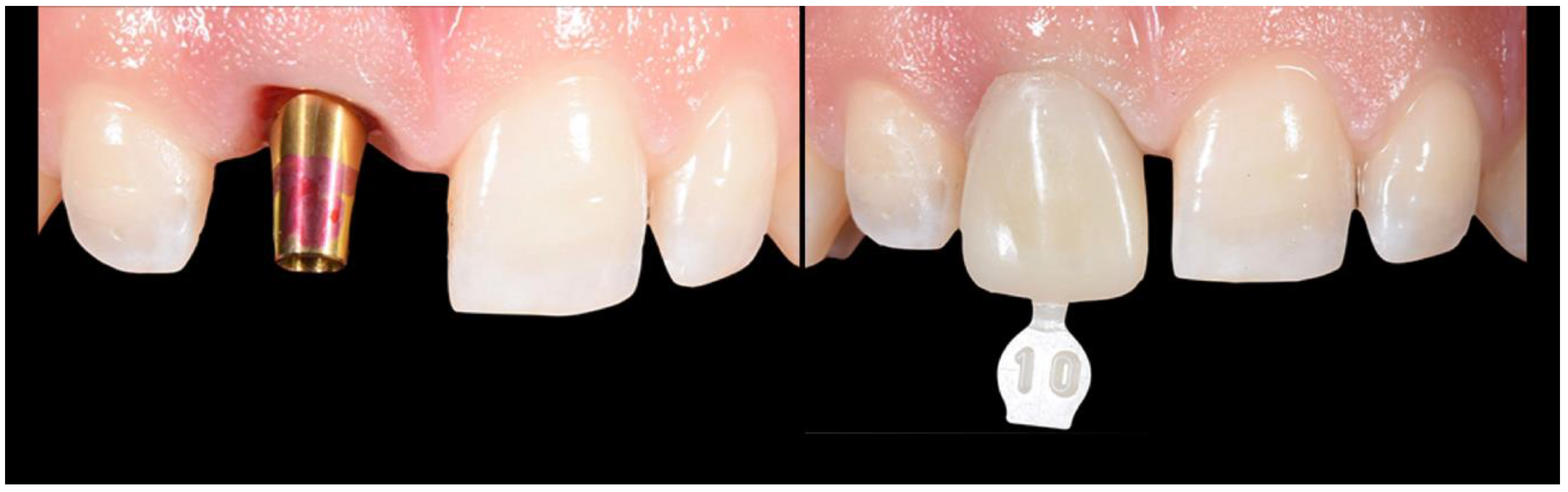
2.5. Impression Stage

Approximately 4 weeks later, the soft tissue was conditioned and matured enough to proceed with the impression stage [30] (Figure 17). The transitional restoration was replaced by a scan body or an impression post, and a digital or analogic impression was taken [36,37] (Figure 17). An impression of the opposing arch along with bite registration was also taken, as per standard practice. Finally, intra-oral and extra-oral pictures were taken with and without a color shade guide and suitable filters, in order to provide as much information as possible to the dental technician that would design and fabricate the final prosthesis [38].

2.6. Lab Stage

The dental technician, based on the impressions, bite registration, silicone index, clinical pictures and x-rays and all the information he had now available, proceeded with final prosthesis fabrication (Ivoclar, Vivadent, Swtitzerland). However, the final abutment that the dental technician utilized had to comprise a shoulder with the exact same dimensions as per the second abutment used to support the transitional restoration (Figure 18).

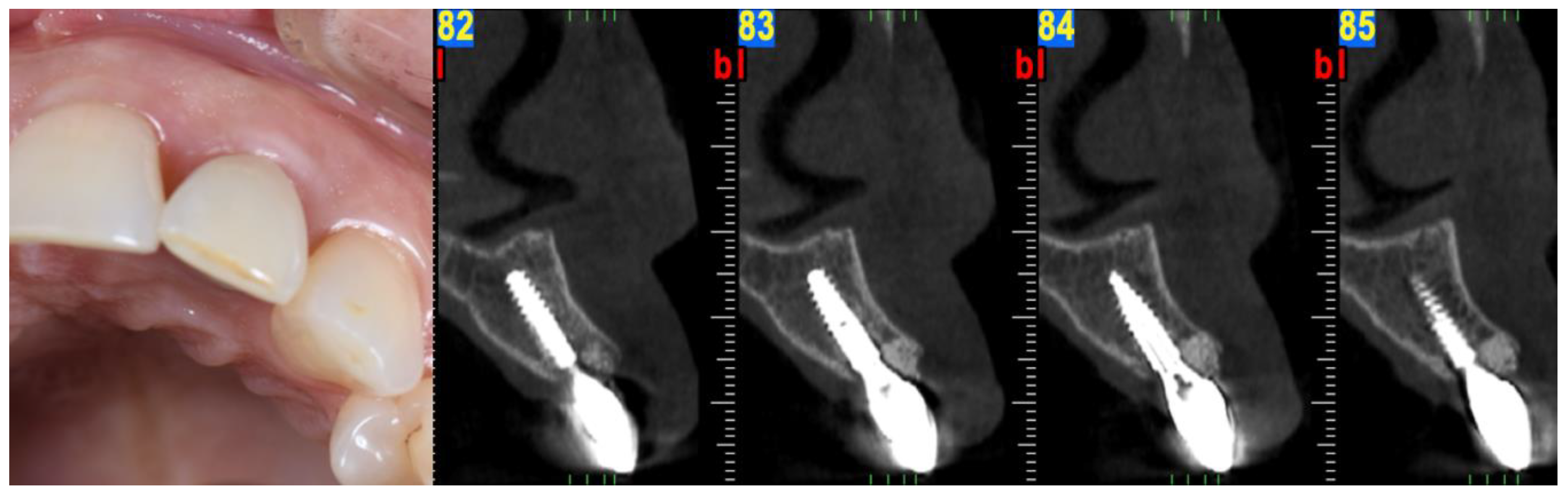
2.7. Prosthesis Delivery

The provisional restoration was un-installed and the final one installed. The proper fit of components was evaluated clinically and radiographically, along with esthetics and phonetics. Occlusal contacts were evaluated in functional occlusion and excursions and adjusted if necessary. The prosthesis was delivered, and oral hygiene was re-enforced to the patient [39,40] (Figure 19).
Clinical and radiographical re-evaluation of the patient, two years later, presented soft and hard tissue stability of the treated site (Figure 20).

3. Case 2

A healthy 35-year-old woman presented for replacement of tooth #2.2 with an implant. The clinical and radiographic evaluation revealed that tooth #2.2 presented with sever buccal bone loss and class I Miller recession defect. The affected tooth was extracted, an appropriate size implant was placed (In-Kone, GlobalD, France) and the rest of the steps of the MMC protocol were utilized following the same methodology as described in the previous case. The one-year post-operative evaluation of this second patient presented a satisfactory result with stable soft and hard tissue (Figure 21, Figure 22, Figure 23, Figure 24, Figure 25, Figure 26, Figure 27, Figure 28 and Figure 29).

4. Discussion

Implants immediately placed and provisionalized in fresh extraction sockets in the esthetic zone are well documented with survival rates similar to traditional delayed protocols [27]. However, the lack of long-term tissue stability resulting in less predictability of esthetic results, has limited the utilization of this protocol to ideal Type I extraction sites [11]. Even in Type I sites, the inclusion of bone and/or soft tissue grafting techniques are often necessary to minimize less than optimal outcomes. The MMC protocol utilizes biologically sound steps in order to further enhance the predictability of the treatment outcomes for both type I sockets as well as type II sites, comprising a thick or thin tissue biotype (Sketch 1 and 2) (Scheme 1 and Scheme 2) [18]. In this article, the authors utilized a socket classification proposed in by Salama and Salama 1993, as we considered it to be the most suitable one [18]. According to more recent classifications, the MMC can be utilized also in Class III sockets that do not present interproximal bone loss and, or class II or III Miller soft tissue recession [19,41]. The MMC protocol does not utilize any vertical incisions. Instead, the surgical design utilizes a partial thickness, supra-periosteal, to create an envelope pouch on the labial aspect of the socket. It is believed that a partial thickness flap is more advantageous relative to a full thickness flap for the MMC technique as it minimizes any compromise to the blood supply originating with the supra-periosteal vascular complex. In addition, a partial thickness flap allows for greater tension-free mobilization of the labial soft tissue. Unlike other techniques which utilize similar partial-thickness labial pouches as receptors of soft tissue grafts, however, the novel aspect of the MMC protocol is this envelope pouch is designed to initiate a control trauma to the periosteum that will lead in the formation of a blood clot, and potentially stimulate osteoprogenitor cells coming from the periosteum to occupy the area [42,43,44]. In combination with the proposed vertical mattress suturing technique, the protocol’s design allows the application of a vertical pull-force at the line angles instead of a horizontal pressure-force to the mid buccal side of the treatment site. Moreover, the location of the vertical mattress sutures constrains the blood clot in a mesio-distal direction between the lateral line angles, allowing it to form and expand in an apico-coronal direction just on the buccal portion of the site without expanding towards the areas of the adjacent teeth [45]. The mobilized buccal tissue with the support of the blood clot is guided by the pull-force to migrate coronally, improving at the same time its vertical location and thickness [45,46]. As the healing process progresses and the inflammation moderates, the coronally migrated soft tissue remains supported, supra-crestally, by portions of the low turnover BRG and resorbable membrane that are purposefully located supra-crestally to provide for a scaffold at the supra-crestal zone of the healing socket [42,47]. Specifically, the membrane is critical to maintaining the graft particles in place and minimizing the popcorn effect often seen in bone grafted cases with thin soft tissue biotype. Moreover, due to the modification and adaptation of its supra-socket portion, the membrane is placed tension free and does not apply any lateral force to the BRG. Similar approaches that tag and/or suture the membrane at the lingual aspect of the socket, can apply pressure on the BRG during the steps of adaptation, moving part of the BRG away from the buccal side, where most of the socket remodeling will take place and thus the BRG is mostly needed [48]. There are several studies that support the utilization of a connective tissue graft within a partial thickness pouch on the buccal aspect of the socket [49,50]. Although this approach appears to improve the stability of the soft tissue, it is a common clinical observation that the addition of the connective tissue graft (CTG) can potentially affect the color and volume of the tissue, making it look different than that of the adjacent sites. The color changes observed are strongly related with the origin of the CTG and the time that has lapsed from the time of surgery [51,52]. The MMC protocol does not induce any such problems, since no CTG or any other material is introduced into the pouch, but instead the generated blood clot is the foundation behind the changes that occur [42]. The ideal position of an immediately placed implant in the esthetic zone has been well documented and is generally described as the “palatal position” [18]. However, the term “palatally-placed implant”, generates some misconceptions. It is important to note that the sockets in the esthetic zone present different anatomies [26]. A fundamental goal that the clinician needs to fulfil in order to be able to immediately load the implant is to achieve high primary stability by engaging an adequate amount of native bone [53]. Thus, based on the socket’s anatomy and the implant’s size and macro-geometry, the position of the implant body can be located palatally, centered, or even buccally, in order to achieve high primary stability (Scheme 1B). As long as the platform and the neck of the implant (3–4 mm of the coronal part of the implant body) are located a minimum distance of 2 mm from the buccal wall of the socket, the needed conditions for a positive esthetic outcome are met, since this coronal area of the socket is the one mostly affected by the physiologic changes/remodeling that occurs during and after the initial healing period of the socket [5,19]. Thus, we believe that a term such as “palatally-positioned implant neck” is more suitable when describing ideal implant positioning in immediate extraction cases. As far as the depth of the implant is concerned, again several factors can affect the final decision for ideal depth. The size and the horizontal location of the implant platform along with the size of the cervical margin of the prosthesis, in combination, dictate the necessary room for proper emergence angle of the prosthesis and thus need to be accounted for when deciding the ideal depth position for the implant [54]. This depth in reality will be anywhere between 3 to 5 mm from the zenith point of the final prosthesis for the majority of the clinical cases. At the stage of provisionalization, the first provisional restoration is designed with two factors in mind. The first refers to the esthetic appearance of the patient and it is related to the design, texture, and color of its supra-gingival portion. The second factor refers to the healing process of the socket and, in particular, its soft tissue zone. More specifically, the abutment shoulder with its tulip shape and restricted lateral dimensions provides a surface to contain the membrane and the BRG within the soft tissue zone of the socket, while at the same time providing space for the soft issue adaptation and integration [21]. The cervical margin of the prosthesis being located at least 1 mm supra-gingivally and comprising a 90° emergence angle, provides necessary room vertically for the soft tissue to migrate coronally. It is understood that in the case of type II sockets where a gingival recession is present, the margin of the prosthesis should be located 1 mm coronal to the future zenith point of the final prosthesis. Thus, in these cases, the cervical margin of the temporary prosthesis can be located 2, 3, or even more millimeters supra-gingivally at the mid-buccal portion. Other published protocols install a temporary prosthesis with a submergence profile that is identical to the emergence profile of the socket. These protocols aim for the prosthesis to fully occupy and support the existing emergence profile of the soft tissue [55]. However, these protocols allow no room for soft tissue improvement and pose possible risks for the final outcome. In case the prosthesis applies any pressure to the buccal soft tissue and/or the gingival biotype is thin, there is a risk for soft tissue recession, compromising the end result [56]. On the contrary, with MMC, all the support of the supra-crestal soft tissue is provided not by the prosthesis, but instead by the BRG and the membrane. The only prosthetic material that is present sub-gingivally is a narrow portion of the titanium abutment which provides the necessary space and a biocompatible surface that enhance the soft tissue adaptation in a more favorable and predictable way [57]. The MMC protocol involves the use of a second temporary restoration, which we call transitional restoration. The latter is used in order to take advantage of the improved soft tissue quantity and quality achieved by the first phase of treatment and condition of the soft tissue by utilizing the principles of proper cervical tissue conditioning [8,58]. The transitional restoration at this stage comprises an anatomically shaped submergence profile, which applies lateral pressure to the soft tissue, forcing the gingival fibers to obtain an oblique orientation [59]. This lateral pressure also leads the coronally migrated buccal tissue to its final vertical location. This vertical location is level with the zenith of the transitional prosthesis, which mimics the desired final prosthesis, and it is located more apically. This apically forced shift of the marginal, matured soft tissue is accompanied by an increase of its thickness [8]. These two factors increase the marginal tissue thickness and oblique orientation of gingival fibers, in combination, improving the tone and color appearance of the soft tissue [8]. The conditioning of the tissue per se also allows the fabrication of a prosthesis with proper cervical contour that achieves ideal esthetic appearance [29]. The process of the final impression can involve any technique, either digital or analogic. It is important, at this stage, to capture the tissue topography accurately and thus, if needed, it is recommended to utilize proper protocols of impression post customization [60]. During the lab stage, the most critical factor refers to proper communication between the clinician and the lab technician as per standard practice. The only restriction that the MMC proposes is the use of a final abutment that comprises a shoulder that is identical to the one of the temporary abutment used for the support of the transitional restoration. It is understood that an intermediate abutment or a CAD abutment milled in-office can also be utilized in order to serve more options of final abutment-prosthesis assembly, as long as these abutments respect the aforementioned requirements with regards to their design and are used at all involved restorative stages. The difference between the temporary abutments used for the support of the temporary (first) restoration and the transitional restoration refers to their margin. The margin of the temporary restoration extends up to 0.5 mm apical to the existing free gingival margin, while the one of the transitional restoration extends 0.5 mm apical to the future zenith point of the prosthesis. The reason behind this difference is that the first supra-structure is designed in order to allow space for gain in soft tissue height, while the second (transitional) supra-structure is designed in order to condition the soft tissue at the ideal height for the final prosthesis. Since the MMC allows the soft tissue to migrate coronal to the zenith point of the future prosthesis, the transitional prosthesis will now condition/push this tissue laterally and apically and this way will further improve its thickness. The MMC has been tested for sites presenting limited soft tissue recession. Further investigation is required to evaluate the efficiency of the technique in cases involving more severe recessions. All of the prostheses utilized in MMC protocol could be screw-retained, cemented, or screw-cemented [61]. However, since proper cement control can potentially be inadequate and result in biologic complications, a screw-cemented prosthesis design is recommended whenever possible [62,63]. A possible complication a clinician might encounter with the proposed protocol is the accidental tear of the buccal flap when the supra-periosteal pouch is prepared. Since the tear will now be exposing part of the resorbable membrane, it is advisable to avoid suturing of the area, rather leaving the site exposed. In this event meticulous care by the patient is advised with the use of effective anti-microbial rinses or gels, and additionally the clinician must perform frequent monitoring during the initial stages of healing and until complete epithelialization of the area is achieved [64].

5. Conclusions

The proposed protocol presents an alternative approach for cases involving immediate implant placement and provisionalization in type I and type II sockets with Miller class I gingival recession in the esthetic zone. The technique is applicable for cases involving both thick and thin soft tissue phenotypes (Figure 30) [18]. Implant sites that fall into the category of type II sockets and/or their soft tissue biotype are identified as thin, and are associated with high risk for the development of soft tissue recession. Thus, currently available guidelines recommend avoiding the treatment of these sites with immediate implant placement and provisionalization protocols [26,65,66]. This case series report showed that the proposed protocol can be proven effective in achieving an esthetically sound result in these types of sites (Figure 29). In the case of class III sockets, an orthodontic extrusion of the affected tooth can precede in order to enhance the proximal bone and soft tissue levels before MMC can be utilized [18,67]. Table 1 summarizes the potential of the application of the MMC protocol based on different available socket classifications. The MMC protocol has been tested by the authors on more than 25 cases involving both type I and II sockets (with Miller class I recession defects) and a follow-up period of up to 3 years, showing consistent results. A new case series study that evaluates volumetric changes with the MMC protocol in both types of sockets is undergoing. Prospective randomized, controlled clinical trials are needed in order to thoroughly evaluate the efficiency and validity of the proposed protocol before its application on a regular basis can be recommended.

Author Contributions

Conceptualization K.V.; writing—original draft preparation I.V.; review and editing H.S. and M.P. All authors have read and agreed to the published version of the manuscript.

Funding

This research received no external funding.

Conflicts of Interest

The authors declare no conflict of interest.

References

  1. Avila, G.; Galindo, P.; Rios, H.; Wang, H.L. Immediate implant loading: Current status from available literature. Implant Dent. 2007, 16, 235–245. [Google Scholar] [CrossRef] [PubMed]
  2. Amler, M.H. The time sequence of tissue regeneration in human extraction wounds. Oral Surg. Oral Med. Oral Pathol. 1969, 27, 309–318. [Google Scholar] [CrossRef]
  3. Cardaropoli, G.; Araújo, M.; Lindhe, J. Dynamics of bone tissue formation in tooth extraction sites. An experimental study in dogs. J. Clin. Periodontol. 2003, 30, 809–818. [Google Scholar] [CrossRef] [PubMed]
  4. Araújo, M.G.; Sukekava, F.; Wennström, J.L.; Lindhe, J. Ridge alterations following implant placement in fresh extraction sockets; an experimental study in the dog. J. Clin. Periodontol. 2005, 32, 645–665. [Google Scholar] [CrossRef]
  5. Araujo, M.G.; Sukekava, F.; Wennstrom, J.L.; Lindhe, J. Tissue modeling following implant placement in fresh extraction sockets. Clin. Oral Implant. Res. 2006, 17, 615–624. [Google Scholar] [CrossRef]
  6. Araujo, M.G.; Wennstrom, J.L.; Lindhe, J. Modeling of the buccal and lingual bone walls of fresh extraction sites following implant installation. Clin. Oral Implant. Res. 2006, 17, 606–614. [Google Scholar] [CrossRef]
  7. Araújo, M.G.; Lindhe, J. Dimensional ridge alterations following tooth extraction. An experimental study in the dog. J. Clin. Periodontol. 2005, 32, 212–218. [Google Scholar] [CrossRef]
  8. Landsberg, C.J.; Bichacho, N. A modified surgical/prosthetic approach for optimal single implant supported crown. Part I--The socket seal surgery. Pract. Periodontics Aesthet Dent. 1994, 6, 11–17. [Google Scholar]
  9. Hurzeler, M.B.; Zuhr, O.; Schupbach, P.; Rebele, S.F.; Emmanouilidis, N.; Fickl, S. The socket-shield technique: A proof-of-principle report. J. Clin. Periodontol. 2010, 37, 855–862. [Google Scholar] [CrossRef]
  10. Chu, S.J.; Hochman, M.N.; Tan-Chu, J.H.; Mieleszko, A.J.; Tarnow, D.P. A Novel Prosthetic Device and Method for Guided Tissue Preservation of Immediate Postextraction Socket Implants. Int. J. Periodontics Restor. Dent. 2014, 34, S9–S17. [Google Scholar]
  11. Waki, T.; Kan, J.Y. Immediate placement and provisionalization of maxillary anterior single implant with guided bone regeneration, connective tissue graft, and coronally positioned flap procedures. Int. J. Esthet Dent. 2016, 11, 174–185. [Google Scholar]
  12. Chen, S.T.; Buser, D. Esthetic outcomes following immediate and early implant placement in the anterior maxilla--a systematic review. Int. J. Oral Maxillofac Implant. 2014, 29, 186–215. [Google Scholar] [CrossRef] [Green Version]
  13. Tarnow, D.; Chu, S.; Salama, M.; Stappert, C.; Salama, H.; Garber, D.; Sarnachiaro, G.; Sarnachiaro, E.; Gotta, S.; Saito, H. Flapless postextraction socket implant placement in the esthetic zone: Part 1. The effect of bone grafting and/or provisional restoration on facial-palatal ridge dimensional change-a retrospective cohort study. Int. J. Periodontics Restor. Dent. 2014, 34, 323–331. [Google Scholar] [CrossRef]
  14. Chu, S.; Salama, M.; Garber, D.; Salama, H.; Sarnachiaro, G.; Sarnachiaro, E.; Gotta, S.; Reynolds, M.; Saito, H.; Tarnow, D. Flapless Postextraction Socket Implant Placement, Part 2: The Effects of Bone Grafting and Provisional Restoration on Peri-implant Soft Tissue Height and Thickness—A Retrospective Study. Int. J. Periodontics Restor. Dent. 2015, 35, 803–809. [Google Scholar] [CrossRef] [Green Version]
  15. Amato, F.; Polara, G.; Spedicato, G.A. Tissue Dimensional Changes in Single-Tooth Immediate Extraction Implant Placement in the Esthetic Zone: A Retrospective Clinical Study. Int. J. Oral Maxillofac Implant. 2018, 33, 439–447. [Google Scholar] [CrossRef] [Green Version]
  16. Mitsias, M.M.; Bratos, M.; Siormpas, K.; Pikos, M.A.; Kotsakis, G.A.; Root Membrane Group. Longitudinal Soft Tissue Changes during Periodontal Ligament-Mediated Immediate Implant Placement with the Root-Membrane Technique. Int. J. Oral Maxillofac Implant. 2020, 35, 379–385. [Google Scholar] [CrossRef]
  17. Gluckman, H.; Salama, M.; Du Toit, J. A retrospective evaluation of 128 socket-shield cases in the esthetic zone and posterior sites: Partial extraction therapy with up to 4 years follow-up. Clin. Implant Dent Relat. Res. 2018, 20, 122–129. [Google Scholar] [CrossRef]
  18. Salama, H.; Salama, M. The role of orthodontic extrusive remodeling in the enhancement of soft and hard tissue profiles prior to implant placement: A systematic approach to the management of extraction site defects. Int. J. Periodontics Restor. Dent. 1993, 13, 312–333. [Google Scholar]
  19. Elian, N.; Cho, S.C.; Froum, S.; Smith, R.B.; Tarnow, D.P. A simplified socket classification and repair technique. Pract. Proced Aesthet Dent. 2007, 19, 99–104. [Google Scholar]
  20. De Jong, K.J.; Abraham-Inpijn, L. A risk-related patient-administered medical questionnaire for dental practice. Int. Dent. J. 1994, 44, 471–479. [Google Scholar]
  21. Blanco, J.; Carral, C.; Argibay, O.; Liñares, A. Implant placement in fresh extraction sockets. Periodontology 2000 2019, 79, 151–167. [Google Scholar] [CrossRef] [PubMed]
  22. Fiorillo, L.; Cicciù, M.; D’Amico, C.; Mauceri, R.; Oteri, G.; Cervino, G. Finite Element Method and Von Mises Investigation on Bone Response to Dynamic Stress with a Novel Conical Dental Implant Connection. BioMed Res. Int. 2020, 2020, 2976067. [Google Scholar] [CrossRef] [PubMed]
  23. Covani, U.; Cornelini, R.; Calvo-Guirado, J.L.; Tonelli, P.; Barone, A. Bone remodeling around implants placed in fresh extraction sockets. Int. J. Periodonticsrestorative Dent. 2010, 30, 601–607. [Google Scholar]
  24. Rojas-Vizcaya, F. Biological aspects as a rule for single implant placement. The 3A-2B rule: A clinical report. J. Prosthodont. 2013, 22, 575–580. [Google Scholar] [CrossRef]
  25. Canullo, L.; Fedele, G.R.; Iannello, G.; Jepsen, S. Platform switching and marginal bone-level alterations: The results of a randomized-controlled trial. Clin. Oral Implant. Res. 2010, 21, 115–121. [Google Scholar] [CrossRef] [PubMed]
  26. Canullo, L.; Pesce, P.; Patini, R.; Antonacci, D.; Tommasato, G. What Are the Effect of Different Abutment Morphologies on Peri-implant Hard and Soft Tissue Behavior? A Systematic Review and Meta-Analysis. Int. J. Prosthodont. 2020, 33, 297–306. [Google Scholar] [CrossRef]
  27. Iasella, J.M.; Greenwell, H.; Miller, R.L.; Hill, M.; Drisko, C.; Bohra, A.A.; Scheetz, J.P. Ridge preservation with freeze-dried bone allograft and a collagen membrane compared to extraction alone for implant site development: A clinical and histologic study in humans. J. Periodontol. 2003, 74, 990–999. [Google Scholar] [CrossRef] [PubMed]
  28. Horowitz, R.; Holtzclaw, D.; Rosen, P.S. A review on alveolar ridge preservation following tooth extraction. J. Evid. Based Dent. Pract. 2012, 12 (Suppl. 3), 149–160. [Google Scholar] [CrossRef]
  29. Castellon, P.; Casadaban, M.; Block, M.S. Techniques to facilitate provisionalization of implant restorations. J. Oral Maxillofac Surg. 2005, 63, 72–79. [Google Scholar] [CrossRef] [PubMed]
  30. Kan, J.Y.K.; Rungcharassaeng, K.; Deflorian, M.; Weinstein, T.; Wang, H.L.; Testori, T. Immediate implant placement and provisionalization of maxillary anterior single implants. Periodontology 2000 2018, 77, 197–212. [Google Scholar] [CrossRef]
  31. Chung, S.; McCullagh, A.; Irinakis, T. Immediate loading in the maxillary arch: Evidence-based guidelines to improve success rates: A review. J. Oral Implant. 2011, 37, 610–621. [Google Scholar] [CrossRef] [PubMed]
  32. Buser, D.; Sennerby, L.; De Bruyn, H. Modern implant dentistry based on osseointegration: 50 years of progress, current trends and open questions. Periodontology 2000 2017, 73, 7–21. [Google Scholar] [CrossRef] [PubMed]
  33. Wittneben, J.G.; Buser, D.; Belser, U.C.; Brägger, U. Peri-implant soft tissue conditioning with provisional restorations in the esthetic zone: The dynamic compression technique. Int. J. Periodontics Restor. Dent. 2013, 33, 447–455. [Google Scholar] [CrossRef] [Green Version]
  34. Furze, D.; Byrne, A.; Alam, S.; Wittneben, J.G. Esthetic Outcome of Implant Supported Crowns with and Without Peri-Implant Conditioning Using Provisional Fixed Prosthesis: A Random-ized Controlled Clinical Trial. Clin. Implant. Dent Relat. Res. 2016, 18, 1153–1162. [Google Scholar] [CrossRef] [PubMed]
  35. Chen, M.H.; Lyons, K.; Tawse-Smith, A.; Ma, S. Resonance Frequency Analysis in Assessing Implant Stability: A Retrospective Analysis. Int. J. Prosthodont. 2019, 32, 317–326. [Google Scholar] [CrossRef]
  36. Lee, S.J.; Gallucci, G.O. Digital vs. conventional implant impressions: Efficiency outcomes. Clin. Oral Implant. Res. 2013, 24, 111–115. [Google Scholar] [CrossRef]
  37. Donovan, T.E.; Chee, W.W. A review of contemporary impression materials and techniques. Dent. Clin. N. Am. 2004, 48, 445–470. [Google Scholar] [CrossRef]
  38. Terry, D.A.; Snow, S.R.; McLaren, E.A. Contemporary dental photography: Selection and application. Compend. Contin. Educ. Dent. 2008, 29, 440. [Google Scholar]
  39. Rösing, C.K.; Fiorini, T.; Haas, A.N.; Muniz, F.W.M.G.; Oppermann, R.V.; Susin, C. The impact of maintenance on peri-implant health. Braz. Oral Res. 2019, 33, e074. [Google Scholar] [CrossRef] [Green Version]
  40. Sheridan, R.A.; Decker, A.M.; Plonka, A.B.; Wang, H.L. The Role of Occlusion in Implant Therapy: A Comprehensive Updated Review. Implant Dent. 2016, 25, 829–838. [Google Scholar] [CrossRef]
  41. Miller, P.D., Jr. A classification of marginal tissue recession. Int. J. Periodontics Restor. Dent. 1985, 5, 8–13. [Google Scholar]
  42. Ballini, A.; Scacco, S.; Coletti, D.; Pluchino, S.; Tatullo, M. Mesenchymal Stem Cells as Promoters, Enhancers, and Playmakers of the Translational Regenerative Medicine. Stem Cells Int. 2017, 2017, 3292810. [Google Scholar] [CrossRef] [PubMed] [Green Version]
  43. Porcaro, G.; Busa, A.; Bianco, E.; Caccianiga, G.; Maddalone, M. Use of aPartial-thickness Flap for Guided Bone Regeneration in the Upper Jaw. J. Contemp. Dent. Pract. 2017, 18, 1117–1121. [Google Scholar] [PubMed]
  44. Lin, Z.; Fateh, A.; Salem, D.M.; Intini, G. Periosteum: Biology and applications in craniofacial bone regeneration. J. Dent. Res. 2014, 93, 109–116. [Google Scholar] [CrossRef] [PubMed] [Green Version]
  45. Lassere, B. The vertical mattress suture in periodontal flap surgery. Inf. Dent. 1983, 65, 3825–3830. [Google Scholar] [PubMed]
  46. Kumar, K.; Sharma, R.K.; Tewari, S.; Narula, S.C. Use of modified vertical internal mattress suture versus simple loop interrupted suture in modified Widman flap surgery: A randomized clinical study. Quintessence Int. 2019, 50, 732–740. [Google Scholar]
  47. Chu, S.J.; Salama, M.A.; Salama, H.; Garber, D.A.; Saito, H.; Sarnachiaro, G.O.; Tarnow, D.P. The dual-zone therapeutic concept of managing immediate implant placement and provisional restoration in anterior extraction sockets. Compend. Contin. Educ. Dent. 2012, 33, 524–534. [Google Scholar]
  48. Tan-Chu, J.H.; Tuminelli, F.J.; Kurtz, K.S.; Tarnow, D.P. Analysis of buccolingual dimensional changes of the extraction socket using the “ice cream cone” flapless grafting technique. Int. J. Periodontics Restor. Dent. 2014, 34, 399–403. [Google Scholar] [CrossRef]
  49. Atieh, M.A.; Alsabeeha, N.H.M. Soft tissue changes after connective tissue grafts around immediately placed and restored dental implants in the esthetic zone: A systematic review and meta-analysis. J. Esthet. Restor. Dent. 2020, 32, 280–290. [Google Scholar] [CrossRef]
  50. Grunder, U. Crestal ridge width changes when placing implants at the time of tooth extraction with and without soft tissue augmentation after a healing period of 6 months: Report of 24 consecutive cases. Int. J. Periodontics Restor. Dent. 2011, 31, 9–17. [Google Scholar]
  51. Zucchelli, G.; Tavelli, L.; McGuire, M.K.; Rasperini, G.; Feinberg, S.E.; Wang, H.L.; Giannobile, W.V. Autogenous soft tissue grafting for periodontal and peri-implant plastic surgical reconstruction. J. Periodontol. 2020, 91, 9–16. [Google Scholar] [CrossRef] [PubMed]
  52. Gluckman, H.; Du Toit, J.; Pontes, C.C.; Hille, J. Hyperplastic Response Following Soft Tissue Augmentation in the Esthetic Zone. Clin. Adv. Periodontics 2019, 9, 50–54. [Google Scholar] [CrossRef] [PubMed]
  53. Tettamanti, L.; Andrisani, C.; Bassi, M.A.; Vinci, R.; Silvestre-Rangil, J.; Tagliabue, A. Immediate loading implants: Review of the critical aspects. Oral Implant. 2017, 10, 129–139. [Google Scholar] [CrossRef] [PubMed]
  54. Saadoun, A.P.; LeGall, M.; Touati, B. Selection and ideal tridimensional implant position for soft tissue aesthetics. Pract Periodontics Aesthet Dent. 1999, 11, 1063–1072. [Google Scholar] [PubMed]
  55. de Siqueira, R.A.C.; Cabral, B.L.; de Siqueira, G.R.; Mendonça, G.; Wang, H.L. Using Digital Technique to Obtain the Ideal Soft Tissue Contour in Immediate Implants with Provisionalization. Implant Dent. 2019, 28, 411–416. [Google Scholar] [CrossRef]
  56. Lee, C.T.; Sanz-Miralles, E.; Zhu, L.; Glick, J.; Heath, A.; Stoupel, J. Predicting bone and soft tissue alterations of immediate implant sites in the esthetic zone using clinical parameters. Clin. Implant Dent. Relat. Res. 2020, 22, 325–332. [Google Scholar] [CrossRef]
  57. Vela, X.; Rodríguez, X. The State of the Art of the Implant-Abutment Design to Maximize the Peri-Implant Tissue Potential. In Implants in the Aesthetic Zone; Schoenbaum, T., Ed.; Springer: Cham, Switzerland, 2019. [Google Scholar]
  58. González-Martín, O.; Lee, E.; Weisgold, A.; Veltri, M.; Su, H. Contour Management of Implant Restorations for Optimal Emergence Profiles: Guidelines for Immediate andDelayed Provisional Restorations. Int. J. Periodontics Restor. Dent. 2020, 40, 61–70. [Google Scholar] [CrossRef]
  59. López-López, P.J.; Mareque-Bueno, J.; Boquete-Castro, A.; Raya, A.A.-S.; Martínez-González, J.M.; Calvo-Guirado, J.L. The effects of healing abutments of different size and anatomic shape placed immediately in extraction sockets on peri-implant hard and soft tissues. A pilot study in foxhound dogs. Clin. Oralimplants Res. 2016, 27, 90–96. [Google Scholar] [CrossRef]
  60. Vergoullis, I.; DDS, M.S.; Valavanis, K.D.D.S.; Badell, C.D.D.S.; Papadopoulos, G.C.D.T. The one functional position, implant level, indirect impression technique: Description of the technique and a case report. JIACD 2019, 11, 14–23. [Google Scholar]
  61. Wittneben, J.G.; Millen, C.; Brägger, U. Clinical performance of screw- versus cement-retained fixed implant-supported reconstructions--a systematic review. Int. J. Oral Maxillofac Implant. 2014, 29, 84–98. [Google Scholar] [CrossRef] [Green Version]
  62. Linkevicius, T.; Vindasiute, E.; Puisys, A.; Linkeviciene, L.; Maslova, N.; Puriene, A. The influence of the cementation margin position on the amount of undetected cement. A prospective clinical study. Clin. Oral Implant. Res. 2013, 24, 71–76. [Google Scholar] [CrossRef] [PubMed]
  63. Helvey, G.A. A Simple Technique for Fabricating a Screw-Retained/Cemented Implant-Supported Crown. Compend. Contin. Educ. Dent. 2017, 38, 153–159. [Google Scholar] [PubMed]
  64. Cantore, S.; Ballini, A.; Mori, G.; Dibello, V.; Marrelli, M.; Mirgaldi, R.; De Vito, D.; Tatullo, M. Anti-plaque and antimicrobial efficiency of different oral rinses in a 3-day plaque accumulation model. J. Biol. Regul. Homeost Agents. 2016, 30, 1173–1178. [Google Scholar] [PubMed]
  65. Sicilia-Felechosa, A.; Pereira-Fernández, A.; García-Lareu, J.; Bernardo-González, J.; Sicilia-Blanco, P.; Cuesta-Fernández, I. Flapless immediate implant placement and provisionalization in periodontal patients: A retrospective consecutive case-series study of single-tooth sites with dehiscence-type osseous defects. Clin. Oral Implant. Res. 2020, 31, 229–238. [Google Scholar] [CrossRef]
  66. Buser, D.; Chappuis, V.; Belser, U.C.; Chen, S. Implant placement post extraction in esthetic single tooth sites: When immediate, when early, when late? Periodontol 2000 2017, 73, 84–102. [Google Scholar] [CrossRef]
  67. Salama, H.; Salama, M.A.; Garber, D.; Adar, P. The interproximal height of bone: A guidepost to predictable aesthetic strategies and soft tissue contours in anterior tooth replacement. Pract. Periodontics Aesthet Dent. 1998, 10, 1131–1141. [Google Scholar]
  68. Chu, S.J.; Sarnachiaro, G.O.; Hochman, M.N.; Tarnow, D.P. Subclassification and Clinical Management of Extraction Sockets with Labial Dentoalveolar Dehiscence Defects. Compend. Contin. Educ. Dent. 2015, 36, 518–520. [Google Scholar]
  69. El Chaar, E.; Oshman, S.; Fallah Abed, P. Single-Rooted Extraction Sockets: Classification and Treatment Protocol. Compend. Contin. Educ. Dent. 2016, 37, 537–541. [Google Scholar]
Figure 1. Pre-operative clinical conditions; thin gingival biotype and marginal apical dislocation of free gingival margin on tooth #1.1.
Applsci 10 08944 g001
Figure 2. Pre-operative Cone-beam computed tomography systems (CBCT) images; evident resorption of tooth #1.1 and thin buccal plate.
Applsci 10 08944 g002
Figure 3. Pre-operative clinical conditions; buccal dislocation of tooth #1.1 is evident.
Applsci 10 08944 g003
Figure 4. Atraumatic extraction of affected tooth with the use of periotomes and generation of partial thickness pouch flap with a micro-blade.
Applsci 10 08944 g004
Scheme 1. Cross sectional views of the critical steps incorporated into marginal migration concept (MMC) protocol.
Applsci 10 08944 sch001
Scheme 2. Frontal view of some of the critical steps of the MMC protocol.
Applsci 10 08944 sch002
Figure 5. Osteotomy, occlusal view of the implant position, abutment adjustment, and connection.
Applsci 10 08944 g005
Figure 6. Slow absorbable membrane shaping and placement in the alveolus in contact with the internal wall of the buccal plate prior to BRG introduction.
Applsci 10 08944 g006
Figure 7. Slow absorbable bone substitute material is packed to fill the gap and membrane adaptation.
Applsci 10 08944 g007
Figure 8. Vertical mattress sutures and radiographic control.
Applsci 10 08944 g008
Figure 9. Rubber dam adaptation and fabrication of the first provisional restoration so that its cervical portion is limited supra-gingivally after connection.
Applsci 10 08944 g009
Figure 10. Different views of the available space between the marginal tissue and the provisional restoration.
Applsci 10 08944 g010
Figure 11. First re-evaluation. Comparison of pre-op and current adaptation of the soft tissue, where marginal migration in a coronal direction is evident.
Applsci 10 08944 g011
Figure 12. Second re-evaluation at 4 weeks. Clinical image immediately after suture removal.
Applsci 10 08944 g012
Figure 13. Three months post-op re-evaluation. Soft tissue conditions at time of removal of the first provisional restoration.
Applsci 10 08944 g013
Figure 14. Installation of new abutment and try in of transitional prosthesis.
Applsci 10 08944 g014
Figure 15. Fabrication and relining of the second provisional (transitional) restoration in order to guide the maturation of the per implant soft tissue to the desired architecture.
Applsci 10 08944 g015
Figure 16. Facial view of the transitional restoration after cementation.
Applsci 10 08944 g016
Figure 17. Impression stage. Comparison of soft tissue topography at time of transitional restoration installation and removal 4 weeks later. Digital impression with scan post is taken.
Applsci 10 08944 g017
Figure 18. Prosthesis design and clinical installation. Two veneers cemented on both implant abutment and adjacent tooth #21 have been utilized to enhance the esthetic result.
Applsci 10 08944 g018
Figure 19. Final prostheses installed.
Applsci 10 08944 g019
Figure 20. Clinical and radiographic re-evaluation 2 years post loading.
Applsci 10 08944 g020
Figure 21. Pre-operative clinical conditions. Hopeless tooth #2.2 presents with Miller class I recession.
Applsci 10 08944 g021
Figure 22. Gingival display upon smiling. Radiographic evaluation reveals severe bone loss both on buccal and lingual aspect.
Applsci 10 08944 g022
Figure 23. Pre-operative clinical conditions. Hopeless tooth #2.2 presents with Miller class I recession and thin tissue biotype.
Applsci 10 08944 g023
Figure 24. MMC protocol involving atraumatic extraction, supra-periosteal pouch flap, abutment, membrane and BRG instalment, and suturing.
Applsci 10 08944 g024
Figure 25. Immediate post-op view and clinical images at time of suture removal where the coronal marginal migration of the soft tissue is evident.
Applsci 10 08944 g025
Figure 26. Clinical images at time of first temporary prosthesis removal and at time of transitional prosthesis removal, demonstrating the soft tissue cervical contouring achieved.
Applsci 10 08944 g026
Figure 27. Clinical image. One year post loading.
Applsci 10 08944 g027
Figure 28. Clinical image. One year post loading.
Applsci 10 08944 g028
Figure 29. Clinical image and radiographic control. One year post loading.
Applsci 10 08944 g029
Figure 30. Pre-op (top row) and post-op (bottom row) images of three cases, demonstrating the marginal migration of soft tissue effect achieved with the MMC protocol.
Applsci 10 08944 g030
Table 1. Summary of different socket classifications available and potential applicability of the MMC protocol.
Salama H, Salama M [18]CLASS ICLASS IICLASS III
MMC++
Chu SJ et al. [68]TYPE ATYPE BTYPE C
MMC+++
(If recession defect is class I Miller)
Ellian N et al. [19].TYPE ITYPE IITYPE III
MMC+++
(If recession defect is class I Miller)
El Chaar E et al. [69]GRADE IGRADE IIGRADE III
MMC++
Publisher’s Note: MDPI stays neutral with regard to jurisdictional claims in published maps and institutional affiliations.

