1. Introduction
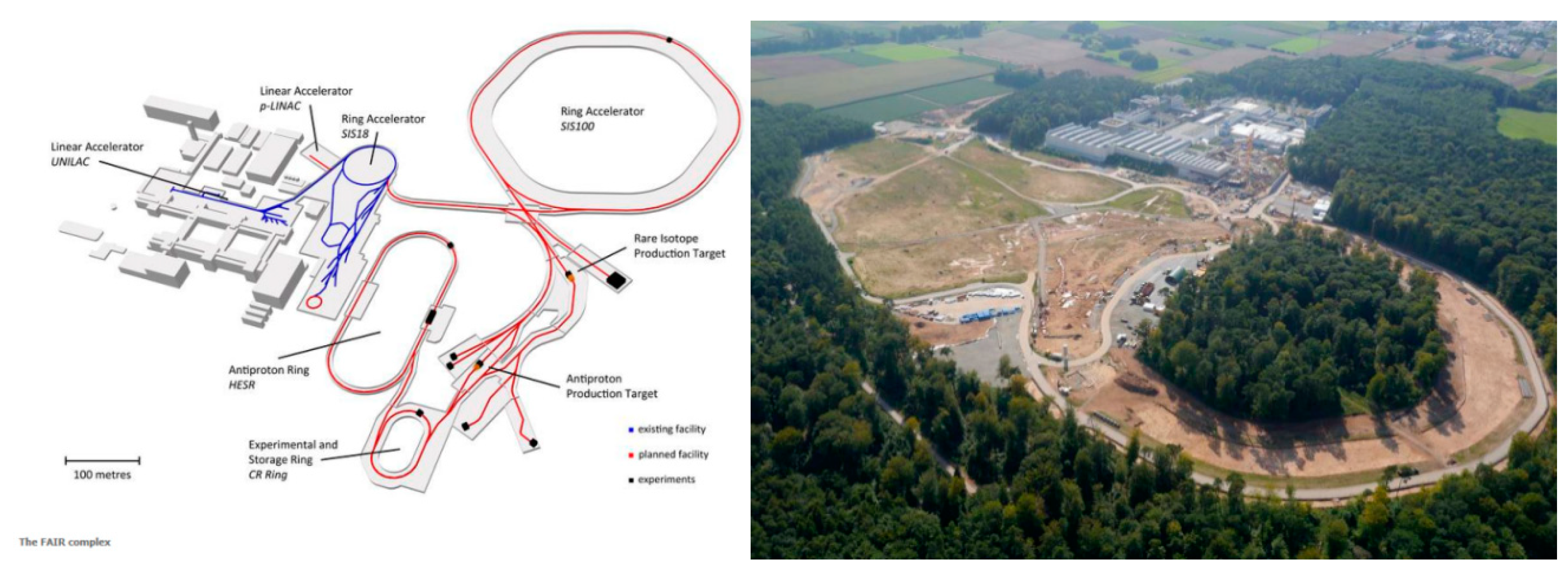
The Facility for Antiproton and Ion Research (FAIR) will be unique and one of the most complex international accelerator facilities for the research on antiprotons and ions. It is already under construction by an international collaboration at the GSI Helmholtzzentrum fur Schwerionenforschung near Darmstadt, Germany. Its core, a double-ring NbTi superconducting-technology-based SIS100 heavy-ion synchrotron, with a circumference of 1100 m, will be associated with a complex system of cooler, storage rings and experimental setups (see
Figure 1). This accelerator will deliver ion beams of unprecedented intensities and energies. Thus, intensive secondary beams can also be produced, providing antiprotons and exotic nuclei for groundbreaking experiments.
A cryogenic system is required to cool the magnet system into a superconducting state. It distributes the cryogenic refrigerator’s cooling capacity to the superconducting devices by supercritical or liquid helium. The design of exemplary supercritical helium cryogenic transfer lines is presented in [
1,
2], and an overview of the European X-ray Free Electron Laser (XFEL), with a similar cryogenic system, is provided in [
3].
The cryogenic systems for the SIS100 synchrotron are comprised of a helium refrigerator, a distribution system, and the SIS100 local cryogenic system. The local cryogenics consist of the following:
three feed boxes (FBs), each distributing subcooled liquid helium and electric current to two sectors;
six current lead boxes (CLBs) connected to the feed boxes, providing electric current from normal conduction to the superconducting transfer system;
six bypass lines (BPLs), where each distributes the cooling and electric current from the feed box to the magnets.
Design, manufacturing, and installation of all local cryogenic components of SIS100 is a Polish in-kind contribution to the FAIR project, realized by Wroclaw University of Science and Technology. The in-kind contribution is coordinated by a Polish shareholder—the Jagiellonian University in Krakow. In the paper, several technical solutions were presented, including two types of internal floating-suspension system based on stainless steel rods and aramid cables. The aramid cable suspension has been previously used in cryogenics applications in [
4,
5,
6,
7]; a trial of the application in SIS100 BPL was presented.
2. Bypass Line Design Requirements
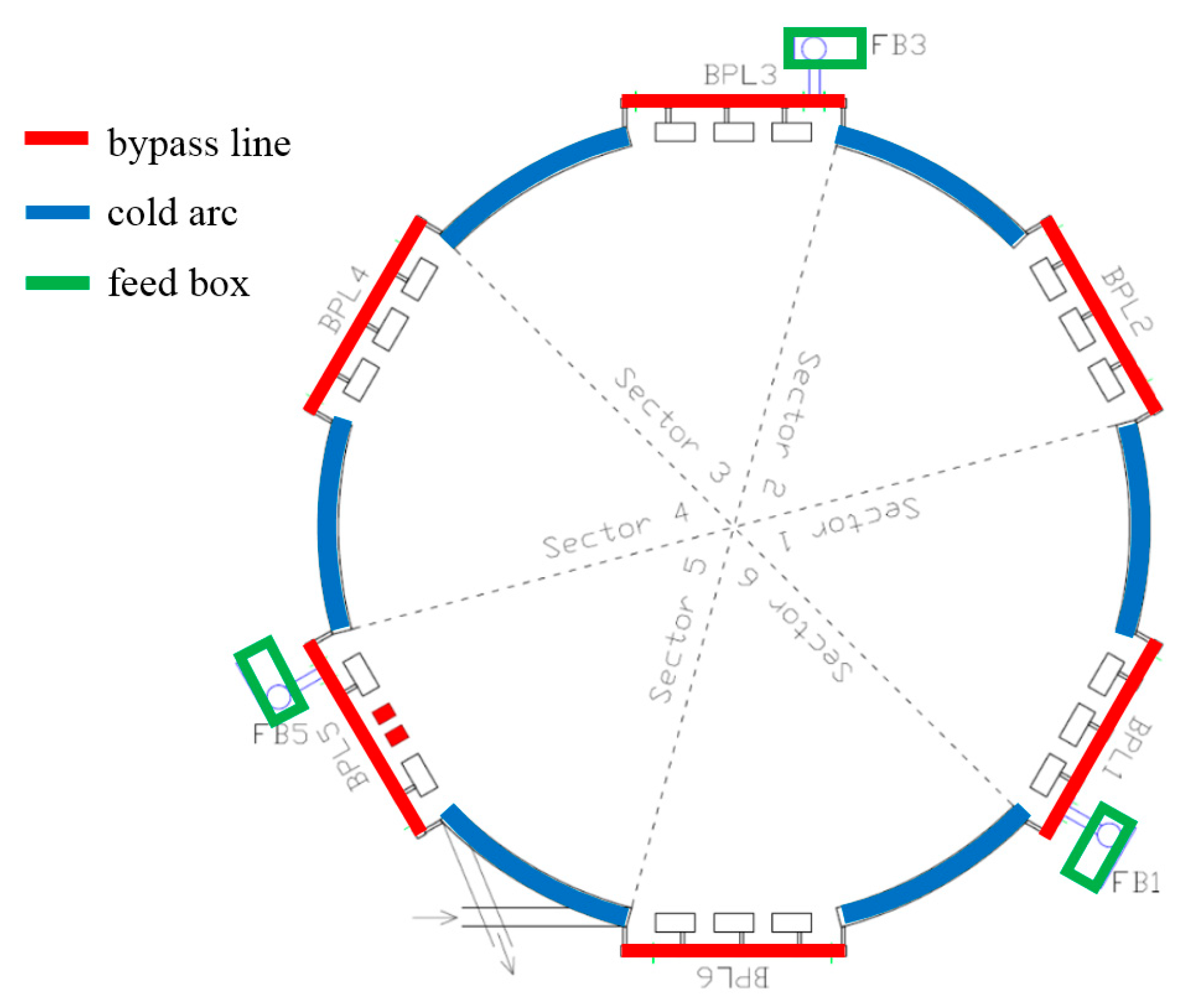
The synchrotron SIS100 is divided into six sectors (see
Figure 2), each composed of an arc section containing a number of superconducting magnets and a straight section containing three superconducting quadrupole magnets (QDMs). Between the QDMs of the straight sections, warm accelerating components are located. Thus, electric current and liquid helium need to be bypassed at the warm components.
The single bypass line consists of five process pipes and four pairs of superconducting busbars. The SIS100 ring contains six bypass lines with a length of about 50 m each, connected hydraulically and electrically to the magnets. It is designed to bypass warm gaps between magnets on the straight sections of SIS100 and to provide electric current and liquid helium to arcs sections and quadrupole magnets. The total length of the bypass lines is equal to about 300 m.
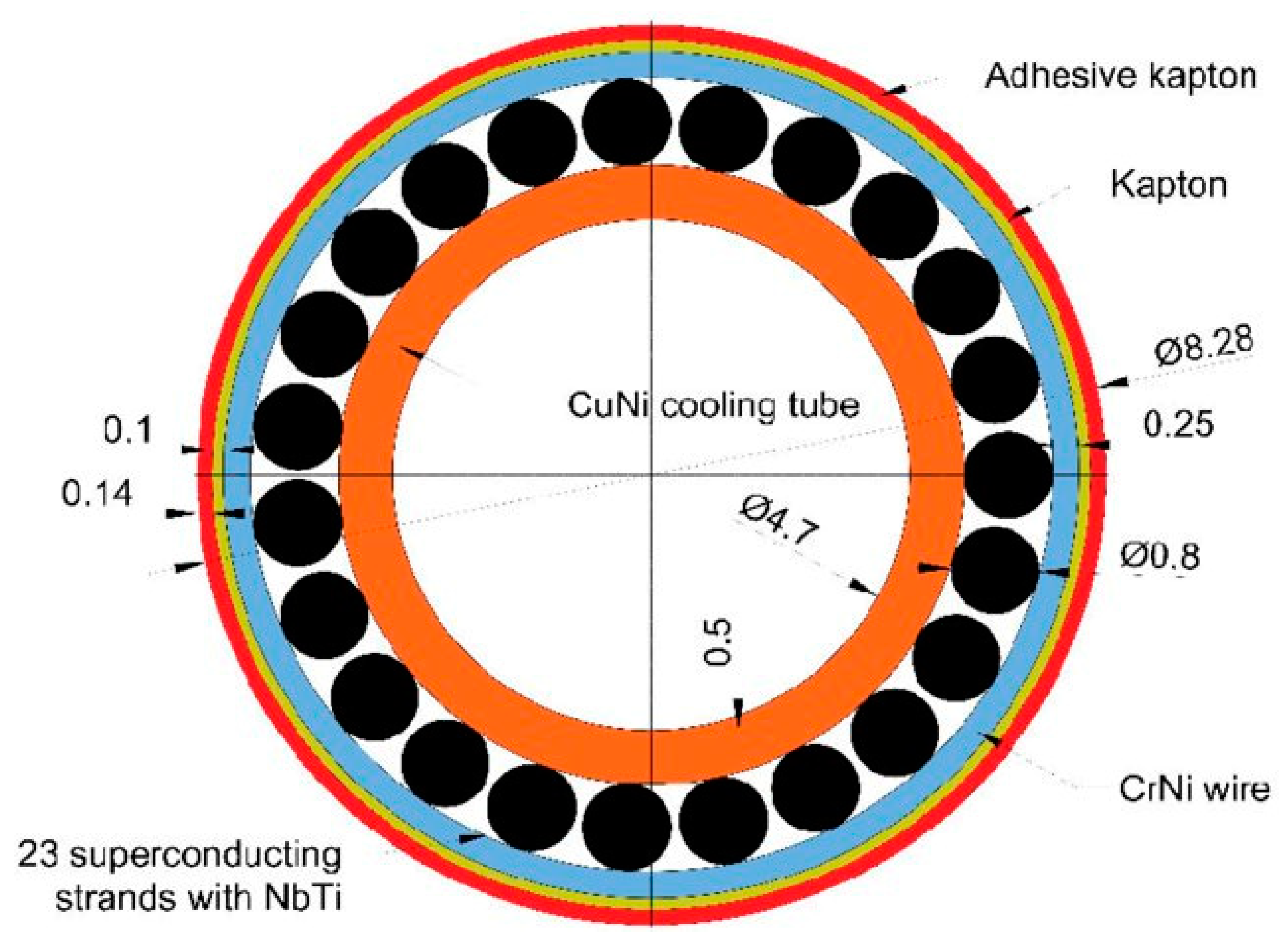
Electric power and liquid helium are provided to sections of the bypass line by short feed-in lines from three feed boxes, one per two sectors. The electric power is transferred from feed boxes by the NbTi superconducting busbars, cooled by a two-phase liquid–vapor mixture of helium. The required helium mass flow adjustment is done by isenthalpic throttling in a capillary [
8]. A cross-section of the NbTi superconductor is shown in
Figure 3. The outer superconducting wires are cooled by the helium flowing through the central CuNi tube. Details of the cable structure are given in [
9].
The main innovative feature of the cryogenic bypass line is transferring the electrical current and helium in a single vacuum insulation vessel. In existing transfer systems, those functions are usually separated. The standard transfer line contains only hydraulic process pipes [
11]. The coexistence of busbars and helium process pipes in one vacuum vessel allows the reduction of the number and overall size of the required vacuum vessels, which is very important in the limited space of the SIS100 tunnel. The space restrictions are more pronounced in the second accelerator, SIS300, which is planned to be located in the same tunnel, above SIS100 [
12].
The magnets of SIS100 will be ramped up with an electrical current of up to 13.2 kA and a frequency of up to 1 Hz. Four busbar pairs supply the electrical current independently to the different magnet circuits, all of which need to be integrated in the BPL. Due to the significant total BPL length of 300 m and usage in SIS100 of the independently controlled fast-ramping magnets, the presence of the cross-talk between busbars pairs and parasitic capacities can affect the quality of the magnetic fields [
13,
14]. The layout of the BPL cross-section was determined by maximizing the distance between the busbars pairs.
One of the requirements for the magnetic system is the extremely high precision of the magnet alignment on the whole 1100-m-long ring of the SIS100. The high precision of the magnet’s cold structure position must not be affected by pressure forces or by thermal contraction stresses from the BPL. Therefore, the next significant feature of the BPL is to provide helium at a pressure of up to 18 bar(a) to the magnets without exerting any significant forces on the magnet’s cold structure. Simultaneously, as the magnets will be installed and positioned after BPL installation, the BPL design should allow for the adjustment of the magnet cryostats within a range of ± 15 mm in any direction.
The next feature of the BPL is the partitioning of the SIS100 vacuum space. In order to avoid the risk of catastrophic loss of the insulation vacuum in the whole SIS100 ring by a single leak, the SIS100 vacuum space was divided into fifteen sections separated by vacuum barriers, which are located in the bypass lines. In the case of a helium leak in any vacuum section, the BPL vacuum vessel might cool down by approximately 100 K and shrink due to thermal contraction. The vacuum barriers will be loaded with the pressure forces of about 20 kN each, which have to be entirely captured by BPL without transfer of the forces to the magnet’s cold structures. Process pipes in the SIS100 ring are protected against excessive pressure build-up by the safety valves, also located in the bypass lines.
For those reasons, the bypass line has to be designed to be flexible, allowing free movement of the magnet during its adjustment and simultaneously capturing all pressure forces and thermal contractions. The requirement of zero-force exerted on the magnets means that the bypass line needs to be designed with a very limited set of external fixed supports. The design of such a structure is challenging from a mechanical point of view.
The general layout of the SIS100 bypass line is shown in
Figure 4. The specification of the design parameters of the process pipes is presented in
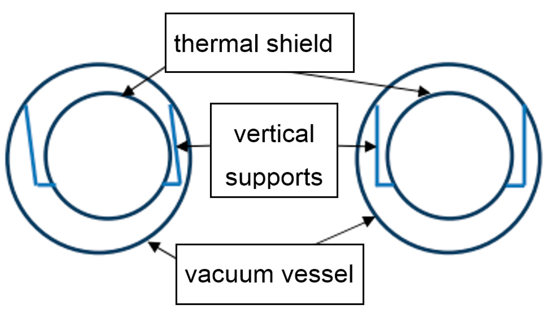
Table 1. The support system is divided into three parts:
external support of the vacuum vessel;
supports of the thermal shield inside the vacuum vessel;
supports of process pipes and superconducting busbars inside the thermal shield.
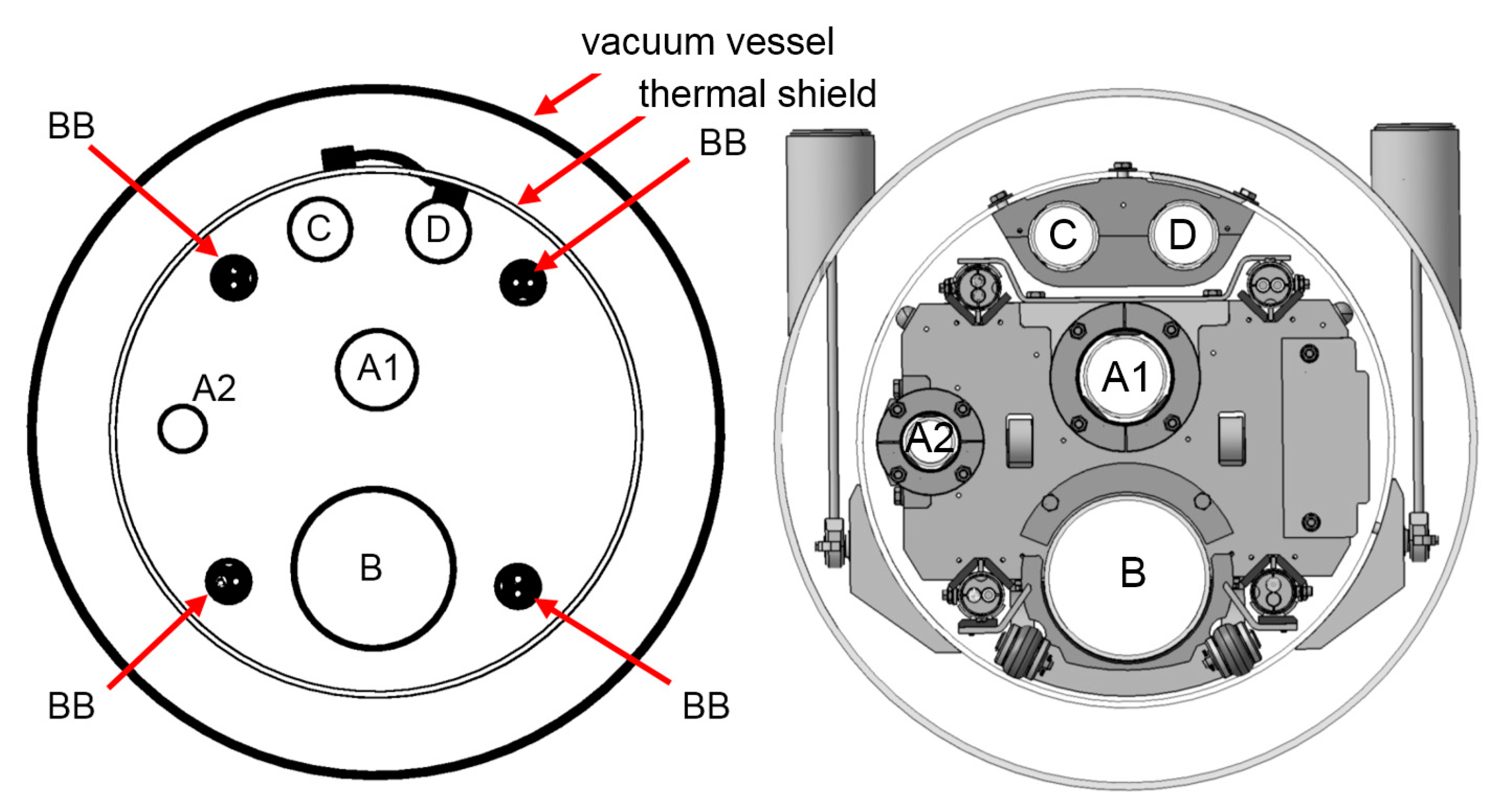
The parameters of the process pipes—temperatures, operating and design pressures—are presented in
Table 1. The busbar system is hydraulically connected between He-supply magnet pipes (A1) and He-return magnet pipes (B). The operating temperature of the superconducting busbars (BBs) is 4.5 K.
3. Mechanical Design of BPL
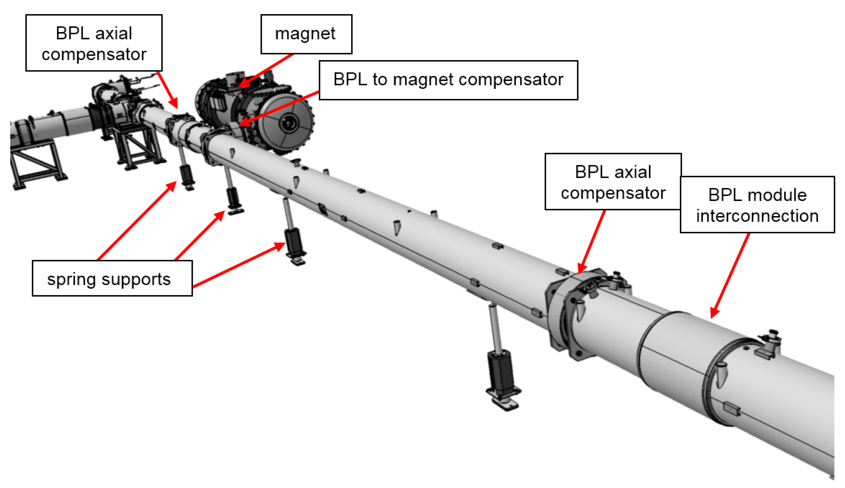
In the vacuum vessel of BPL, there is no separated fixed support in the vertical direction; the only fixed supports are the magnet flanges. The vacuum vessel is elastically supported in the vertical direction by long-stroke spring supports. After adjustment of the spring forces, the supports carry the full weight of the BPL in the desired vertical position. The vacuum vessel is attached to the magnet flanges by corrugated compensators (
Figure 5). These compensators are used only to compensate for the misalignment of the flanges of BPL with flanges of the magnet during the assembly process. After adjustment and flange mounting, the compensators are fixed by four rods, making the connection of BPL modules with the magnets rigid.
As in standard transfer line designs, two additional axial compensators per module are used to increase BPL flexibility and compensate for a thermal contraction in the case of helium leakage.
Axial supports are located at the ends of each BPL to carry the full axial pressure forces acting on the vacuum vessel. The axial supports are separated from magnet axial compensators in order to avoid transferring pressure forces onto the magnet flange.
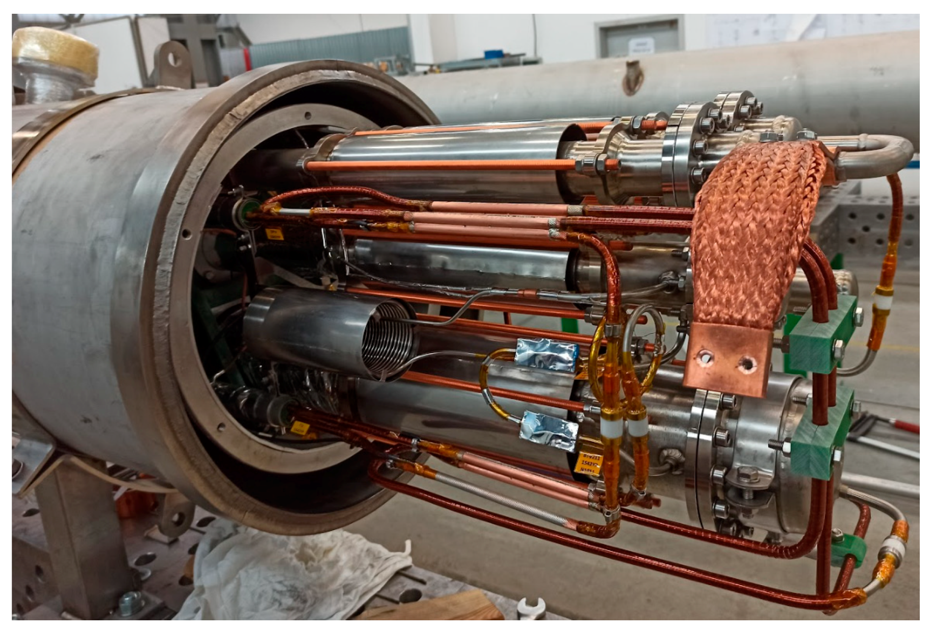
Liquid helium, distributed along the BPL, has a temperature of 4.5 K. In order to avoid significant heat loads from the vacuum vessel, liquid helium process pipes are thermally separated by high-insulation vacuum and multilayer insulation (MLI). The MLI covers process pipe surfaces and all other cold components in vacuum space. In addition, the 4.5 K process pipes are surrounded by a thermal shield (TS) that is kept at a 60–80 K temperature level. This allows the interception of a large amount of heat that would be transferred from the vacuum vessel directly to the liquid helium process pipes. The thermal shield is also cooled with the use of cold, high-pressure helium that circulates in the supply and return lines of the TS circuit. As the thermal shield is made of aluminum, which, by high thermal conductivity, ensures homogenous temperature distribution along the shield, it is thermally coupled with the shield’s return process pipe by flexible braids made of copper. Such design decouples the stresses due to the difference in the stainless steel and aluminum thermal contraction, especially during cool-down and warm-up.
The design of the bypass line uses an innovative concept of the floating cold mass (
Figure 6). Its principle is to remove the internal supports of the BPL cold mass and suspend the entire interior on swinging links. Free movement of the BPL cold mass significantly reduces the forces exerted on the magnets and makes it easier to maintain their stable position relative to the beam axis. Simultaneously, in case of displacement of the cold mass, gravity provides a small centering reaction.
Due to the floating support, the cold structure of the bypass line is able to contract toward the thermal contraction centers of the magnets without compensation elements between the magnet and the BPL.
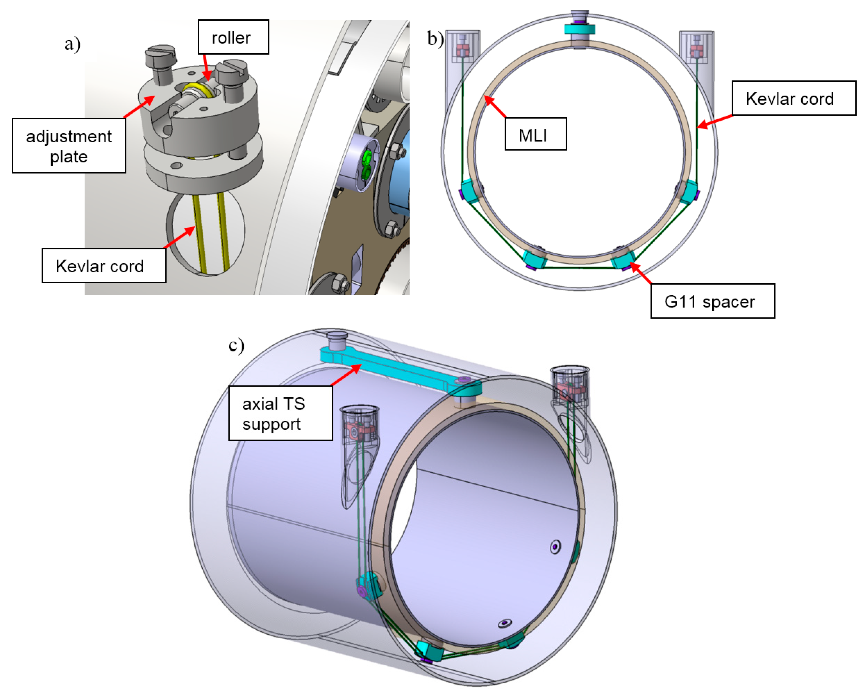
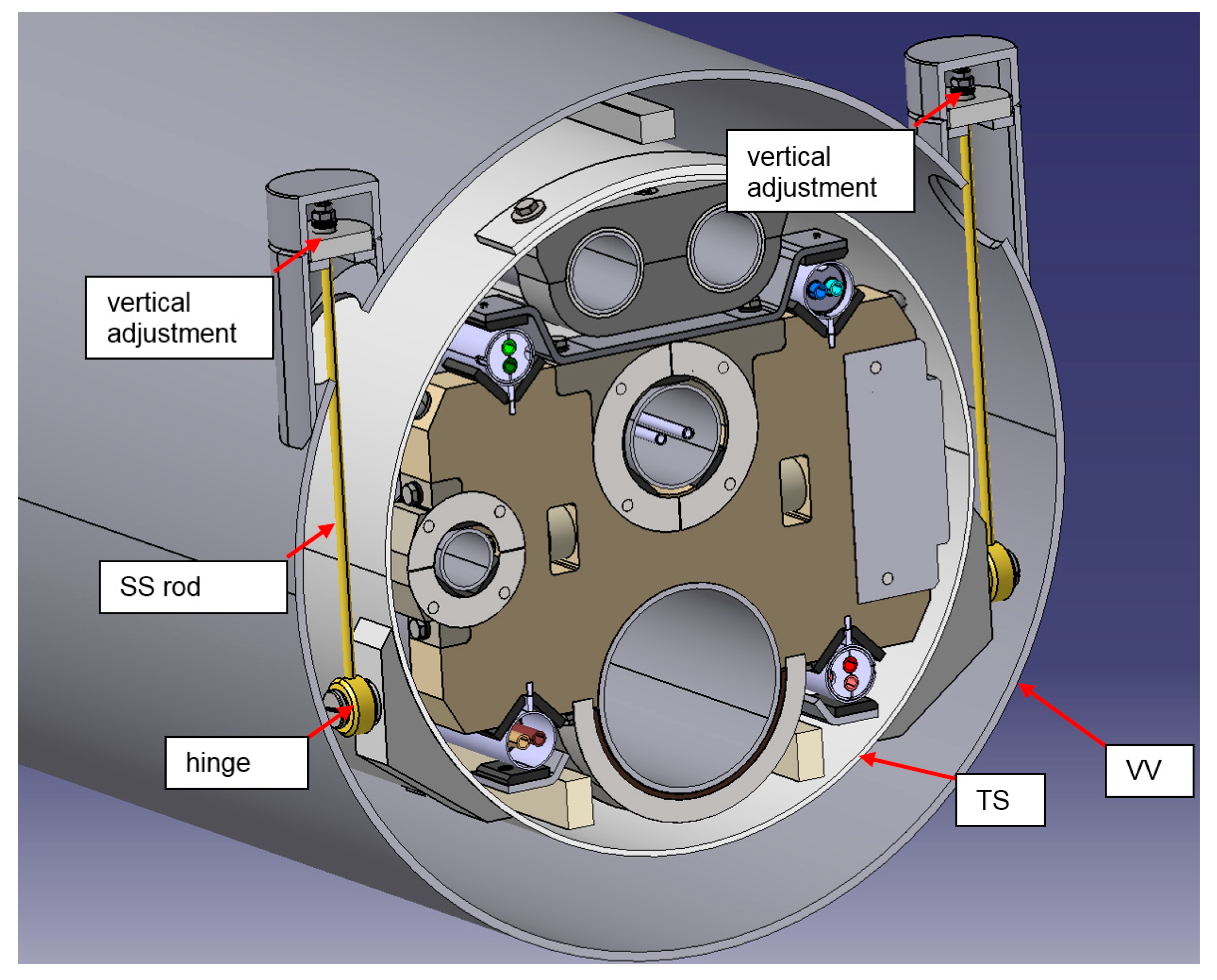
The suspension of the thermal shield was designed in two versions. The first was based on aramid fiber cords (Kevlar 49) with a diameter of 3 mm (
Figure 7 and
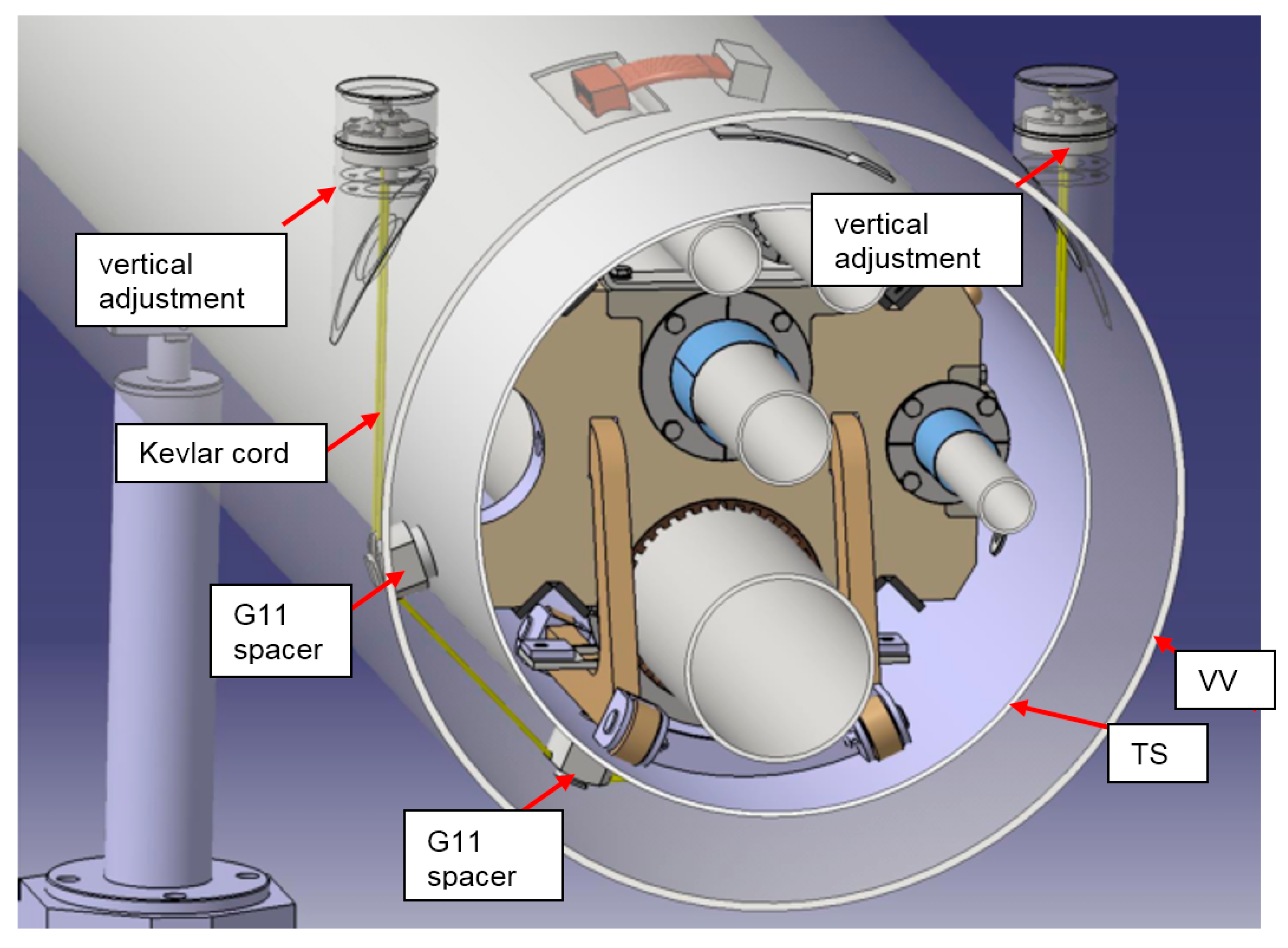
Figure 8). The single cord, in the form of a closed-loop, supports the thermal shield tube by four thermally insulating spacers made of G11 glass fiber laminate to avoid direct thermal contact of the cord and the multilayer insulation (MLI) of the thermal shield. The spacers simultaneously provide 10 mm space for the MLI to avoid its compression. The weight of the thermal shield and all the cold mass inside the thermal shield is distributed among all four spacers and reaction forces are applied to the thermal shield only in the radial direction. The vertical adjustment, shown in
Figure 7a, can be used to balance the forces in all the aramid cords along the BPL module during the manufacturing stage.
Both upper ends of the loop pass through the holes in the vacuum vessel and are supported on rollers with an adjustment range in a vertical direction. The rollers provide the ability of self-balance of the forces in all lines of the aramid cord. Loops are located along the pipe, with a 2.7 m average distance between them. The thermal shield is divided into approximately 6-m-long segments; the axial position of each segment is fixed with the use of a G11 axial support arm (shown in
Figure 7c).
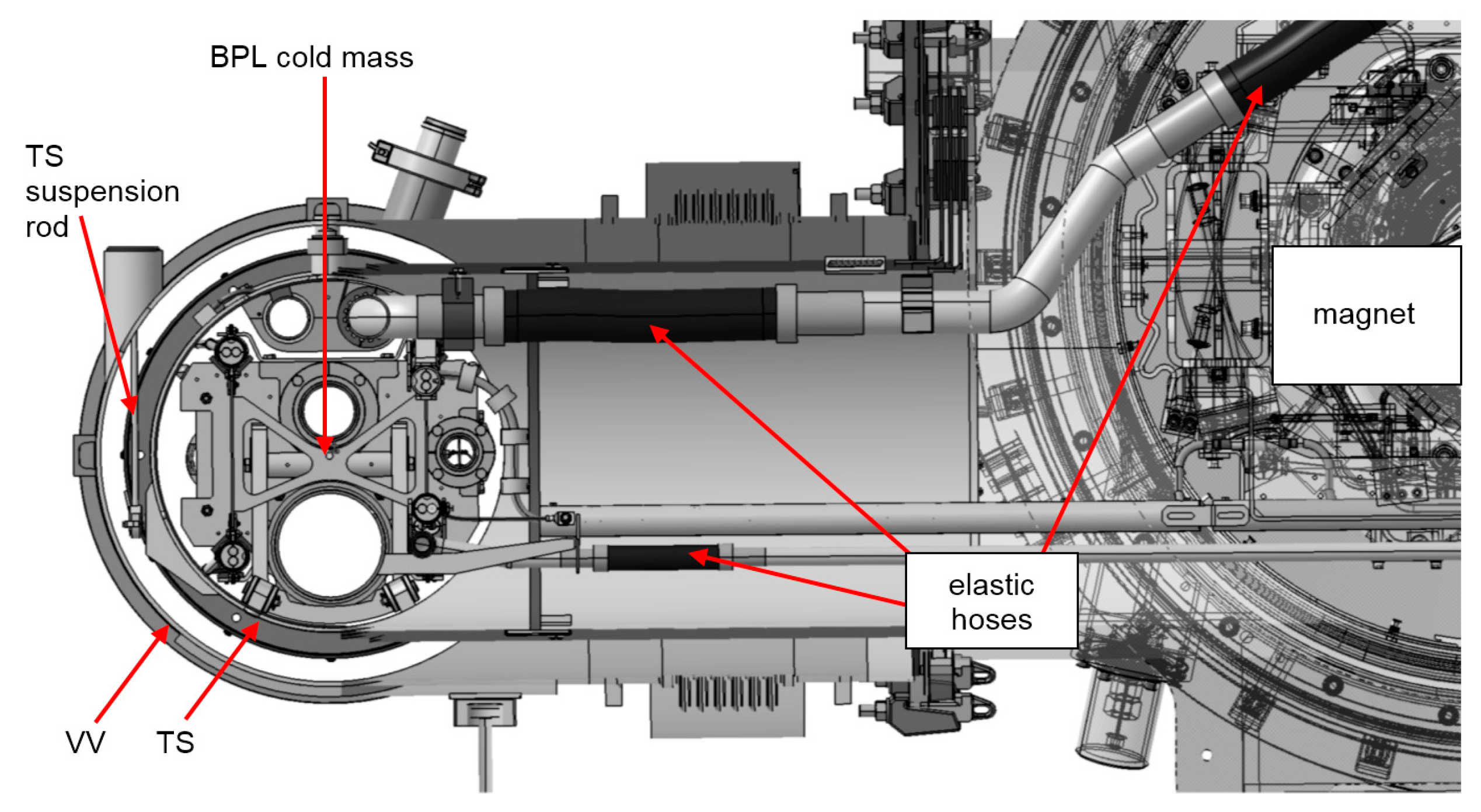
The second concept of the thermal shield suspension is based on the stainless-steel rods instead of aramid cords (
Figure 9). A pair of steel rods are attached to the thermal shield by hinges. Because of the significant force and bending moment acting on the TS, the area of connection to TS is strengthened. Upper ends of the rods are supported by the vacuum vessels with the possibility of vertical adjustment. In
Figure 10, the cold mass suspension system in the area of magnet connection is shown.
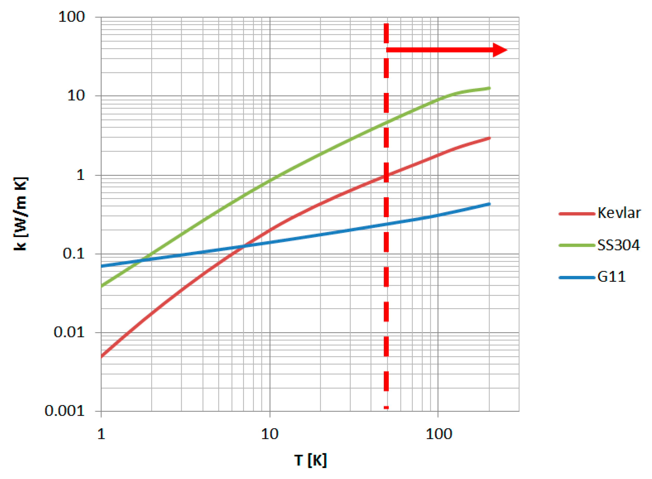
Aramid cord suspension has several advantages compared to steel rod suspension. The ratio of strength to thermal conductivity of Kevlar is much higher than for stainless steel (
Figure 11). The thermal conductivity of Kevlar 49 [
15,
16] at the 50–300 K temperature range is approximately 80% lower than the thermal conductivity of stainless steel. The summary cross-section of the pair of aramid strings is twice smaller than the cross-section of the steel rod because of the higher strength of Kevlar.
In the case of aramid cords, the mechanical load is applied to the TS as a force in the radial direction, distributed among four G11 spacers. No bending moment is applied, and forces can be carried directly by the TS pipe. The loop suspension is also a simpler and cheaper solution.
The only disadvantage of Kevlar cord suspension is the risk of creeping during long-term operation. Even if the load of the aramid cord is well below the yield strength, the plastic material can suffer mechanical creep, a slow increase of plastic deformation that depends on the load, temperature, and time. As a result, the deformation can exceed mechanical tolerances or even cause the loss of mechanical stability.
While aramid cord suspension has been used in some cryogenic applications—SAFIRE, CUORE, MINERvA [
4,
5], there are still very limited data about the long-term use of aramid fibers in cryogenic applications. In [
6], a single Kevlar-braided loop was considered to be a good candidate for internal cryostat suspension. In [
7], the long-term mechanical creep of Kevlar 49 fiber at a temperature of 4.2 K was investigated. The fiber (0.5 mm in diameter) was loaded with a mass of 2.7 kg for a period of 8 months. A 0.004% creep strain was reported. The creep was very limited, but this was measured in a period that was much shorter than the 30 years of planned operation of the SIS100 accelerator and at a temperature of 4.2 K instead of the 80 K of the BPL thermal shield.
The aramid braided-rope designed for the suspension of the SIS100 BPL would have to remain functional for the 30 years of SIS100 operation, with no possibility of exchanging damaged elements of the suspension system. Because of the lack of experimental data for the long-term creep behavior of aramid cords, the second option of steel rod suspension is used.
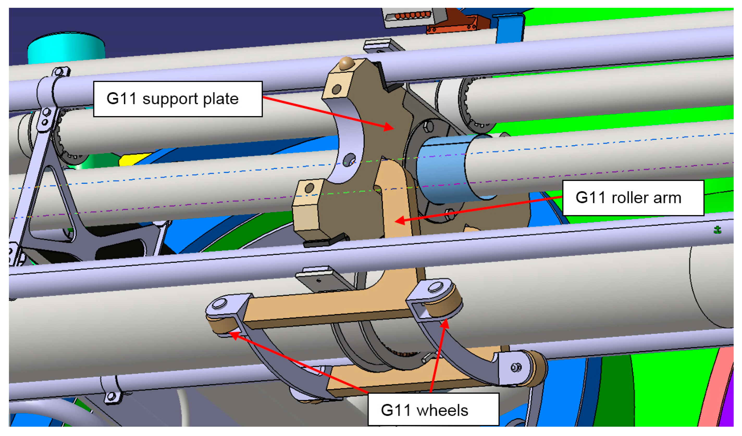
The process pipes are supported inside the thermal shield by G11 support plates. All the plates are clamped onto return pipe B (outer diameter 108 mm). The first plate on the upstream end of the module is a fixed support plate; the other plates are sliding ones. It allows the relative axial movements of the process pipes. At the downstream end of the module, there are axial bellows to compensate for the thermal contraction of the process pipes.
The G11 support plates are supported inside the TS on G11 roller arms equipped with four G11 wheels. The wheels provide sliding support for the G11 plates (
Figure 12).
Busbar pairs are clamped to carry the significant Lorenz forces due to the high electrical current transferred by each busbar pair. These forces act in a repelling manner. The equidistant and short clamping avoids plastic deformation of the superconducting cable. In order to achieve a high-quality magnetic field, the electromagnetic cross-talk between the four busbar pairs has to be minimized [
12,
17] by a stable relative position and, especially, the orientation of the busbar pairs.
The clamped busbar pair is slid into a stainless steel support pipe, providing a stiffness sufficient to keep the BB pair in the correct position with respect to the process pipes and the thermal shield (
Figure 13). The support pipes are supported in the G11 support plates.
During the thermal shrink of the busbars, the clamps slide inside to avoid the axial stresses of the busbars. The support pipes are electrically connected by grounding cables.
At the downstream end of the module, the thermal compensation loops are placed on the busbar pairs. The loop compensates for up to 40 mm of the thermal contraction of the busbars (
Figure 14).

 ,
, 


