A MBSE Application to Controllers of Autonomous Underwater Vehicles Based on Model-Driven Architecture Concepts


Abstract
:1. Introduction
- (1)
- The MBSE methodology, together with MDA components, was adapted for usability in the lifecycle development of AUV controllers.
- (2)
- The designed control capsules are customizable and reusable for many kinds of AUVs.
- (3)
- A planar trajectory-tracking controller of a miniature AUV running on the free surface was developed and evaluated through simulation experiments.
2. AUV Dynamics and Control Architecture
2.1. AUV Dynamic Model for Controlling
2.2. General Control Architecture for an AUV
3. MBSE-Driven Development for an AUV Controller
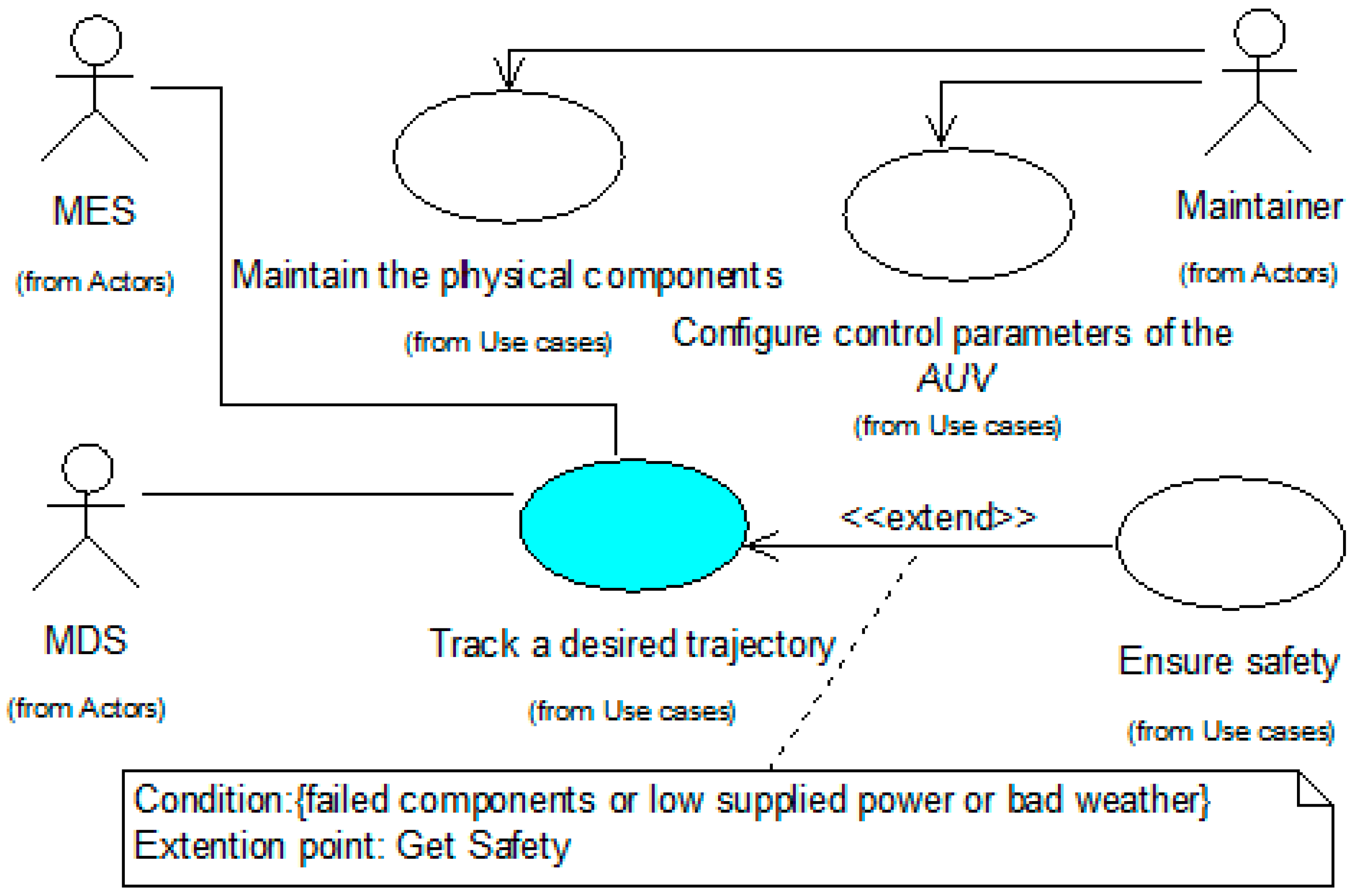
3.1. CIM for an AUV Controller
- -
- MDS is the measurement display system actor, which includes the guidance subsystem and navigation subsystem.
- -
- MES is the marine environment system actor, which represents the marine environmental noises.
- -
- Maintainer is a human actor who has authority to check the physical AUV components and configure system parameters AUV for running AUV tasks.
- -
- “Track a desired trajectory” is a use case study for tracking the target of a predefined path.
- -
- “Ensure safety” is a use case for ensuring system safety.
- -
- “Configure control parameters of the AUV” is a use case for configuring and updating system parameters.
- -
- “Maintain the physical components” is a use case for servicing the whole physical system.
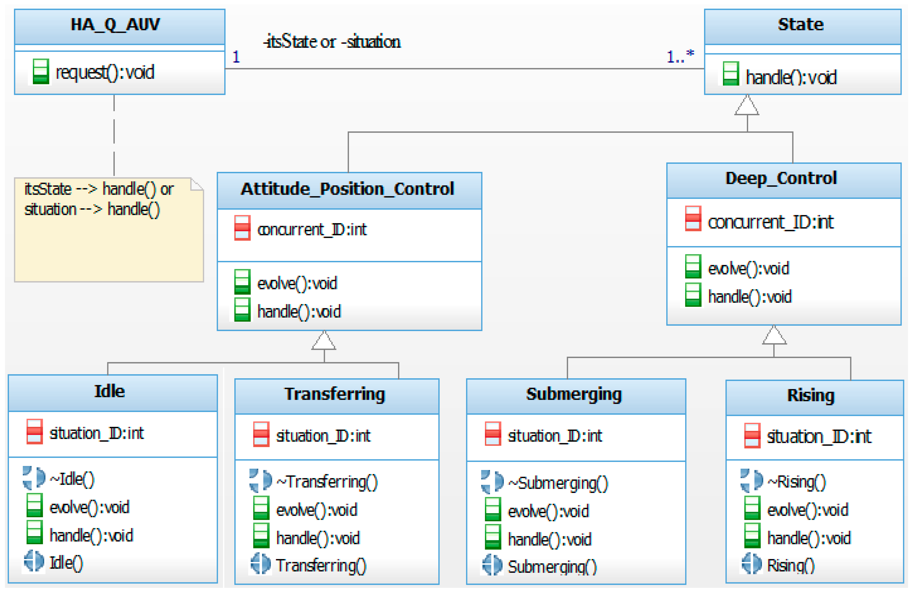
3.2. PIM for an AUV Controller
3.3. PSM for an AUV Controller
4. Application
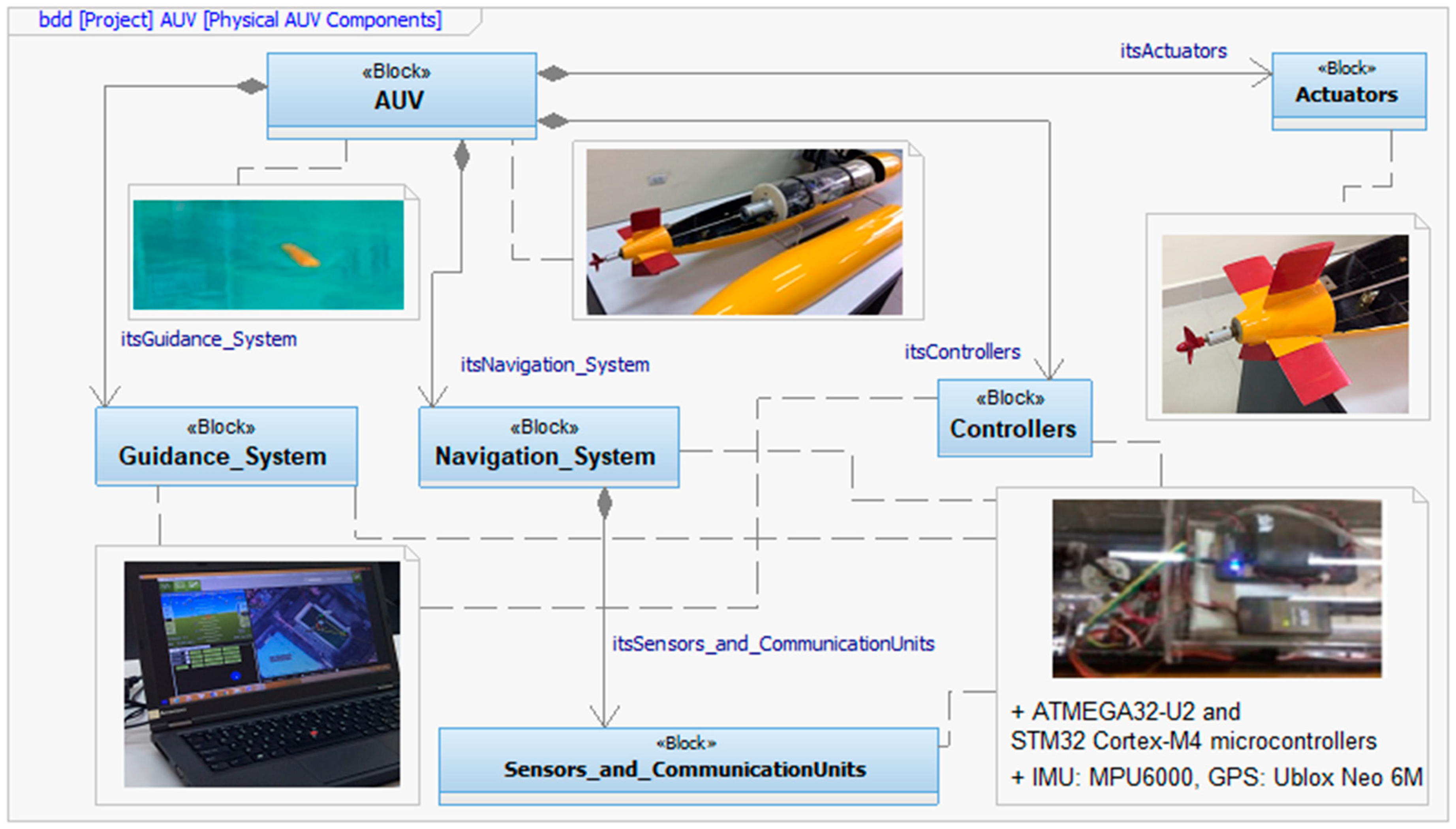
4.1. Physical Application Configurations
4.2. Control Implementation and Test Results
| Algorithm 1. Navigation filter based on the extended Kalman filter (EKF). |
| Function EKF algorithm |
| Step EKF predict |
| Data: |
| Result: |
| ; |
| end |
| Step EKF update |
| Data: |
| Result: |
| ; |
| end |
| Algorithm 2. Navigation filter based on the unscented Kalman filter (UKF). |
| Function UKF algorithm |
| Step UKF predict |
| Data: |
| Result: |
| end |
| Step UKF update |
| Data: |
| Result: |
| end |
5. Conclusions and Future Work
Author Contributions
Funding
Acknowledgments
Conflicts of Interest
Abbreviations
| AUV | Autonomous underwater vehicle | MES | Marine environment system |
| CIM | Computation independent model | MOF | Meta Object Facility |
| CLF | Control Lyapunov functions | OMG | Object Management Group |
| DoF | Degrees of freedom | OOSEM | Object-Oriented Systems Engineering Method |
| EKF | Extended Kalman filter | OPM | Object Process Methodology |
| GPS | Global positioning system | PID | Proportional–integral–derivative |
| HA | Hybrid automata | PIM | Platform independent model |
| Harmony-SE | Harmony for systems engineering | PSM | Platform specific model |
| HDS | Hybrid dynamic system | RPY | Roll, pitch, and yaw |
| IB | Integral backstepping | RUP-SE | Rational Unified Process for Systems Engineering |
| INCOSE | International Council on Systems Engineering | SMC | Sliding-mode control |
| IDE | Implementation development environment | SNAME | Society of Naval Architects and Marine Engineers |
| IGCB | Instantaneous global continuous behavior | SysML | Systems modeling language |
| IMU | Inertial measurement unit | UAF | Unified architecture framework |
| LQ | Linear quadratic | UKF | Unscented Kalman filter |
| LOS | Line-of-sight | UML | Unified modeling language |
| MBSE | Model-based systems engineering | UT | Unscented transform |
| MDA | Model-driven architecture | XMI | XML metadata interchange |
| MDS | Measurement display system | XML | Extensible markup language |
Appendix A

References
- Hien, N.V.; He, N.V.; Truong, V.T.; Diem, P.G. Specifying the Model-Driven Architecture and Real-Time Unified Modeling Language to Implement an AUV Controller. Research Project Report, Funded by State of Vietnam, KC03.TN05/11-15; Hanoi University of Science and Technology: Hanoi, Vietnam, 2013. [Google Scholar]
- Sivčev, S.; Coleman, J.; Omerdić, E.; Dooly, G.; Toal, D. Underwater manipulators: A review. Ocean Eng. 2018, 163, 431–450. [Google Scholar] [CrossRef]
- Wynn, R.B.; Huvenne, V.A.I.; Bas, T.P.L.; Murton, B.J.; Connelly, D.P.; Bett, B.J.; Ruhl, H.A.; Morris, K.J.; Peakall, J.; Parsons, D.R.; et al. Autonomous Underwater Vehicles (AUVs): Their past, present and future contributions to the advancement of marine geoscience. Mar. Geol. Int. J. Mar. Geol. Geochem. Geophys. 2014, 352, 451–468. [Google Scholar] [CrossRef] [Green Version]
- Petillot, Y.R.; Antonelli, G.; Casalino, G.; Ferreira, F. Underwater Robots: From Remotely Operated Vehicles to Intervention-Autonomous Underwater Vehicles. IEEE Robot. Autom. Mag. 2019, 26, 94–101. [Google Scholar] [CrossRef]
- Han, M.; Lyu, Z.; Qiu, T.; Xu, M. A Review on Intelligence Dehazing and Color Restoration for Underwater Images. IEEE Trans. Syst. Man Cybern. Syst. 2020, 50, 1820–1832. [Google Scholar] [CrossRef]
- Bao, J.; Li, D.; Qiao, X.; Rauschenbach, T. Integrated navigation for autonomous underwater vehicles in aquaculture: A review. Inf. Process. Agric. 2020, 7, 139–151. [Google Scholar] [CrossRef]
- Eiler, J.H.; Grothues, T.M.; Dobarro, J.A.; Shome, R. Tracking the Movements of Juvenile Chinook Salmon Using an Autonomous Underwater Vehicle under Payload Control. Appl. Sci. 2019, 9, 2516. [Google Scholar] [CrossRef] [Green Version]
- Sheng, M.; Tang, S.; Qin, H.; Wan, L. Clustering Cloud-Like Model-Based Targets Underwater Tracking for AUVs. Sensors 2019, 19, 370. [Google Scholar] [CrossRef] [Green Version]
- Sabet, M.T.; Daniali, H.M.; Fathi, A.; Alizadeh, E. Identification of an Autonomous Underwater Vehicle Hydrodynamic Model Using the Extended, Cubature, and Transformed Unscented Kalman Filter. IEEE J. Ocean. Eng. 2018, 43, 457–467. [Google Scholar] [CrossRef]
- Gibson, S.B.; Stilwell, D.J. Hydrodynamic Parameter Estimation for Autonomous Underwater Vehicles. IEEE J. Ocean. Eng. 2020, 45, 385–394. [Google Scholar] [CrossRef]
- Yao, F.; Yang, C.; Zhang, M.; Wang, Y. Optimization of the Energy Consumption of Depth Tracking Control Based on Model Predictive Control for Autonomous Underwater Vehicles. Sensors 2019, 19, 162. [Google Scholar] [CrossRef] [Green Version]
- Henzinger, T.A.; Kopke, P.W.; Puri, A.; Varaiya, P. What‘s Decidable about Hybrid Automata? J. Comput. Syst. Sci. 1998, 57, 94–124. [Google Scholar] [CrossRef] [Green Version]
- Hien, N.V.; Soriano, T. Implementing hybrid automata for developing industrial control systems. In Proceedings of the 8th IEEE-ETFA, Antibes-Juan les Pins, France, 15–18 October 2001; Volume 2, pp. 129–137, ISBN 0-7803-7241-7. [Google Scholar]
- Carloni, L.P.; Passerone, R.; Pinto, A.; Sangiovanni, V.A. Languages and Tools for Hybrid Systems Design; Now Publishers Inc.: Boston, MA, USA, 2006. [Google Scholar]
- Fishwick, P.A. (Ed.) Handbook of Dynamic System Modeling; Taylor & Francis Group: New York, NY, USA, 2007. [Google Scholar]
- Qing, X.; Karimi, H.R.; Niu, Y.; Wang, J. Decentralized unscented Kalman filter based on a consensus algorithm for multi-area dynamic state estimation in power systems. Int. J. Electr. Power Energy Syst. 2015, 65, 26–33. [Google Scholar] [CrossRef]
- Karimi, H.R. A sliding mode approach to H∞ synchronization of master–slave time-delay systems with Markovian jumping parameters and nonlinear uncertainties. J. Frankl. Inst. 2012, 349, 1480–1496. [Google Scholar] [CrossRef] [Green Version]
- Pettersen, K.Y.; Fossen, T.I. Guidance of Autnomous Underwater Vehicles. In Encyclopedia of Robotocs; Ang, M.A., Khatib, O., Sicilano, B., Eds.; Springer: Berlin/Heidelberg, Germany, 2018. [Google Scholar]
- Lei, M. Nonlinear diving stability and control for an AUV via singular perturbation. Ocean Eng. 2020, 197, 11. [Google Scholar] [CrossRef]
- Khalaji, A.K.; Tourajizadeh, H. Nonlinear Lyapounov based control of an underwater vehicle in presence of uncertainties and obstacles. Ocean Eng. 2020, 198, 9. [Google Scholar] [CrossRef]
- Li, S.; Wang, X.; Zhang, L. Finite-Time Output Feedback Tracking Control for Autonomous Underwater Vehicles. IEEE J. Ocean. Eng. 2015, 40, 727–751. [Google Scholar] [CrossRef]
- Zhang, L.; Liu, L.; Zhang, S.; Cao, S. Saturation Based Nonlinear FOPD Motion Control Algorithm Design for Autonomous Underwater Vehicle. Appl. Sci. 2019, 9, 4958. [Google Scholar] [CrossRef] [Green Version]
- Valluru, S.K.; Kaur, M.; Kartikeya, K.; Goel, A.; Dobhal, D. Experimental Investigation of Fully Informed Particle Swarm Optimization tuned Multi Loop L-PID and NL-PID Controllers for Gantry Crane System. Procedia Comput. Sci. 2020, 171, 130–138. [Google Scholar] [CrossRef]
- Sarhadi, P.; Noei, A.R.; Khosravi, A. Model reference adaptive PID control with anti-windup compensator for an autonomous underwater vehicle. Robot. Auton. Syst. 2016, 83, 87–93. [Google Scholar] [CrossRef]
- Guerrero, J.; Torres, J.; Creuze, V.; Chemori, A.; Campos, E. Saturation based nonlinear PID control for underwater vehicles: Design, stability analysis and experiments. Mechatron. Sci. Intell. Mach. 2019, 61, 96–105. [Google Scholar] [CrossRef] [Green Version]
- Kong, F.; Guo, Y.; Lyu, W. Dynamics Modeling and Motion Control of an New Unmanned Underwater Vehicle. IEEE Access 2020, 8, 30119–30126. [Google Scholar] [CrossRef]
- Makdah, A.A.R.A.; Daher, N.; Asmar, D.; Shammas, E. Three-dimensional trajectory tracking of a hybrid autonomous underwater vehicle in the presence of underwater current. Ocean Eng. 2019, 185, 115–132. [Google Scholar] [CrossRef]
- Alaeddini, A.; Morgansen, K.A.; Mesbahi, M. Augmented state feedback for improving observability of linear systems with nonlinear measurements. Syst. Control Lett. 2019, 133, 8. [Google Scholar] [CrossRef]
- Cho, G.R.; Park, D.G.; Kang, H.; Lee, M.J.; Li, J.H. Horizontal Trajectory Tracking of Underactuated AUV using Backstepping Approach. IFAC-PapersOnLine 2019, 52, 174–179. [Google Scholar] [CrossRef]
- Ellenrieder, K.D.V. Stable Backstepping Control of Marine Vehicles with Actuator Rate Limits and Saturation. IFAC-PapersOnLine 2018, 51, 262–267. [Google Scholar] [CrossRef]
- Guerrero, J.; Antonio, E.; Manzanilla, A.; Torres, T.; Lozano, R. Autonomous Underwater Vehicle Robust Path Tracking: Auto-Adjustable Gain High Order Sliding Mode Controller. IFAC-PapersOnLine 2018, 51, 161–166. [Google Scholar] [CrossRef]
- Zhang, G.C.; Huang, H.; Qin, H.D.; Wan, L.; Li, Y.M.; Cao, J.; Su, Y.M. A novel adaptive second order sliding mode path following control for a portable AUV. Ocean Eng. 2018, 151, 82–92. [Google Scholar] [CrossRef]
- Xu, H.; Zhang, G.C.; Sun, Y.S.; Pang, S.; Ran, X.R.; Wang, X.B. Design and Experiment of a Plateau Data-Gathering AUV. J. Mar. Sci. Eng. 2019, 7, 376. [Google Scholar] [CrossRef] [Green Version]
- Wang, X.; Zhang, G.; Sun, Y.; Cao, J.; Wan, L.; Sheng, M.; Liu, Y. AUV near-wall-following control based on adaptive disturbance observer. Ocean Eng. 2019, 190, 17. [Google Scholar] [CrossRef]
- Guerrero, J.; Torres, J.; Creuze, V.; Chemori, A. Adaptive disturbance observer for trajectory tracking control of underwater vehicles. Ocean Eng. 2020, 200, 13. [Google Scholar] [CrossRef] [Green Version]
- Wang, J.; Wang, C.; Wei, Y.; Zhang, C. Sliding mode based neural adaptive formation control of underactuated AUVs with leader-follower strategy. Appl. Ocean Res. 2020, 94, 9. [Google Scholar] [CrossRef]
- Elhaki, O.; Shojaei, K. A robust neural network approximation-based prescribed performance output-feedback controller for autonomous underwater vehicles with actuators saturation. Eng. Appl. Artif. Intell. 2020, 88, 16. [Google Scholar] [CrossRef]
- Kumar, N.; Rani, M. An efficient hybrid approach for trajectory tracking control of autonomous underwater vehicles. Appl. Ocean Res. 2020, 95, 10. [Google Scholar] [CrossRef]
- Yan, Z.; Wang, M.; Xu, J. Robust adaptive sliding mode control of underactuated autonomous underwater vehicles with uncertain dynamics. Ocean Eng. 2019, 173, 802–809. [Google Scholar] [CrossRef]
- Han, S.; Wang, H.; Tian, Y.; Christov, N. Time-delay estimation based computed torque control with robust adaptive RBF neural network compensator for a rehabilitation exoskeleton. ISA Trans. 2020, 97, 171–181. [Google Scholar] [CrossRef] [PubMed]
- Alvarez, J.; Arceo, J.C.; Armenta, C.; Lauber, J.; Bernal, M. An Extension of Computed-Torque Control for Parallel Robots in Ankle Reeducation. IFAC-PapersOnLine 2019, 52, 1–6. [Google Scholar] [CrossRef]
- OMG. Documents Associated with Unified Modeling Language™ (UML® Version 2.5.1): OMG Formal/17-12-05; OMG: Needham, MA, USA, 2017; Available online: http://www.omg.org/spec/UML/ (accessed on 19 April 2019).
- OMG. SysML Specifications Version 1.6: OMG Formal/19-11-01; OMG: Needham, MA, USA, 2019; Available online: https://www.omg.org/spec/SysML/ (accessed on 22 March 2020).
- INCOSE. Systems Engineering Vision 2025; INCOSE: San Diego, CA, USA, 2014. [Google Scholar]
- INCOSE. Model-Based Systems Engineering (MBSE). Available online: https://www.incose.org/ (accessed on 22 January 2020).
- Board, B.E. The Guide to the Systems Engineering Body of Knowledge (SEBoK), V2.2. Available online: https://www.sebokwiki.org/ (accessed on 10 September 2020).
- Estefan, J.A. Survey of Model-Based Systems Engineering (MBSE) Methodologies. Rev B INCOSE Technical Publication, Document No. INCOSE-TD-2007-003-01; INCOSE: San Diego, CA, USA, 2008. [Google Scholar]
- Douglass, B.P. The Telelogic Harmony/ESW process for realtime and embedded development, IBM Corporation Software Group Somers, NY 10589, USA. White Pap. 2008, 2008, 12. [Google Scholar]
- Douglass, B.P. Real-Time Agility: The Harmony/ESW Method for Real-Time and Embedded Systems Development, 1st ed.; Pearson Education: Boston, MA, USA, 2009. [Google Scholar]
- Lykins, H.; Friedenthal, S.; Meilich, A. Adapting UML for an Object Oriented Systems Engineering Method (OOSEM). In Proceedings of the INCOSE International Symposium, Minneapolis, MN, USA, 16–20 July 2020; pp. 490–497. [Google Scholar]
- INCOSE. Object-Oriented SE Method. Available online: https://www.incose.org/incose-member-resources/working-groups/transformational/object-oriented-se-method (accessed on 12 September 2020).
- Cantor, M. Rational Unified Process® for Systems Engineering: RUP SE Version 2.0. Ibm Ration. EdgeWhite Pap. 2003, 2003, 17. [Google Scholar]
- Ingham, M.D.; Rasmussen, R.D.; Bennett, M.B.; Moncada, A.C. Generating requirements for complex embedded systems using State Analysis. Acta Astronaut. 2006, 58, 648–661. [Google Scholar] [CrossRef]
- Dori, D. Object-Process Methodology: A Holistic Systems Paradigm; Springer: New York, NY, USA, 2002. [Google Scholar]
- Dori, D. Model-Based Systems Engineering with OPM and SysML; Springer: New York, NY, USA, 2016. [Google Scholar]
- OMG. Model Driven Architecture (MDA): Guide Revision 2.0 of MDA Guide Version 1.0.1 (12 June 2003); OMG Document ormsc/2014-06-01; OMG: Needham, MA, USA, 2014; Available online: http://www.omg.org/cgi-bin/doc?ormsc/14-06-01 (accessed on 25 July 2019).
- OMG. MDA Success Stories. Available online: https://www.omg.org/mda/products_success.htm (accessed on 24 April 2020).
- Sebastián, G.; Gallud, J.A.; Tesoriero, R. Code generation using model driven architecture: A systematic mapping study. J. Comput. Lang. 2020, 56, 11. [Google Scholar] [CrossRef]
- OMG. Unified Architecture Framework, Version 1.1: Formal/19-11-07; OMG: Needham, MA, USA, 2020; Available online: https://www.omg.org/spec/UAF (accessed on 12 August 2020).
- Agner, L.T.W.; Soares, I.W.; Stadzisz, P.C.; Simão, J.M. A Brazilian survey on UML and model-driven practices for embedded software development. Syst. Softw. 2013, 86, 997–1005. [Google Scholar] [CrossRef]
- Rashid, M.; Anwar, M.W.; Khan, A.M. Toward the tools selection in model based system engineering for embedded systems—A systematic literature review. J. Syst. Softw. 2015, 106, 150–163. [Google Scholar] [CrossRef]
- Freire, L.O.; Oliveira, L.M.; Vale, R.T.S.; Medeiros, M.; Diana, R.E.Y.; Lopes, R.M.; Pellini, E.L.; Barros, E.A. Development of an AUV control architecture based on systems engineering concepts. Ocean Eng. 2018, 151, 157–169. [Google Scholar] [CrossRef]
- Hien, N.V.; He, N.V.; Diem, P.G. A model-driven implementation to realize controllers for Autonomous Underwater Vehicles. Appl. Ocean Res. 2018, 78, 307–319. [Google Scholar] [CrossRef]
- Soriano, T.; Hien, N.V.; Tuan, K.M.; Anh, T.V. An object-unified approach to develop controllers for autonomous underwater vehicles. Mechatron. Sci. Intell. Mach. 2016, 35, 54–70. [Google Scholar] [CrossRef]
- Anwar, M.W.; Rashid, M.; Azam, F.; Kashif, M. Model-based design verification for embedded systems through SVOCL: An OCL extension for SystemVerilog. Des. Autom. Embed. Syst. 2017, 21, 1–36. [Google Scholar] [CrossRef]
- Anwar, M.W.; Rashid, M.; Azam, F.; Kashif, M.; Butt, W.H. A model-driven framework for design and verification of embedded systems through SystemVerilog. Des. Autom. Embed. Syst. 2019, 23, 179–223. [Google Scholar] [CrossRef]
- Soriano, T.; Pham, H.A.; Hien, N.V. Analysis of coordination modes for multi-UUV based on Model Driven Architecture. In Proceedings of the 12th France-Japan and 10th Europe-Asia Congress on Mechatronics, Tsu, Japan, 10–12 September 2018. [Google Scholar]
- OMG. UML Profile for MARTE: UML for Model-Driven Development of Real Time and Embedded Systems (RTES); OMG formal/19-04-02; OMG: Needham, MA, USA, 2019; Available online: https://www.omg.org/spec/MARTE/:OMG (accessed on 26 May 2020).
- Douglass, B.P. Real-Time UML Workshop for Embedded Systems, 2nd ed.; Elsevier: Oxford, UK, 2014. [Google Scholar]
- Selic, B.; Gerard, S. Modeling and Analysis of Real-Time and Embedded Systems with UML and MARTE; Elsevier: Amsterdam, The Netherlands, 2014. [Google Scholar]
- Selic, B. Using UML for modeling complex real-time systems. Lect. Notes Comput. Sci. 1998, 1474, 250–260. [Google Scholar] [CrossRef]
- SNAME. Nomenclature for Treating the Motion of a Submerged Body through a Fluid; SNAME: New York, NY, USA, 1950. [Google Scholar]
- Fossen, T.I. Handbook of Marine Craft Hydrodynamics and Motion Control; John Wiley & Sons: Hoboken, NJ, USA, 2011. [Google Scholar]
- Figueiredo, A.B.; Matos, A.C. MViDO: A High Performance Monocular Vision-Based System for Docking A Hovering AUV. Appl. Sci. 2020, 10, 2991. [Google Scholar] [CrossRef]
- Martínez, N.L.; Ortega, J.F.M.; Castillejo, P.; Martínez, V.B. Survey of Mission Planning and Management Architectures for Underwater Cooperative Robotics Operations. Appl. Sci. 2020, 10, 1086. [Google Scholar] [CrossRef] [Green Version]
- García, J.G.; Espinosa, A.G.; Urquizo, E.C.; Valdovinos, L.G.G.; Jiménez, T.S.; Cabello, J.A.E. Autonomous Underwater Vehicles: Localization, Navigation, and Communication for Collaborative Missions. Appl. Sci. 2020, 10, 1256. [Google Scholar] [CrossRef] [Green Version]
- Yao, F.; Yang, C.; Liu, X.; Zhang, M. Experimental Evaluation on Depth Control Using Improved Model Predictive Control for Autonomous Underwater Vehicle (AUVs). Sensors 2018, 18, 2321. [Google Scholar] [CrossRef] [Green Version]
- Wan, E.A.; Merwe, R.V.D. The Unscented Kalman Filter. In Kalman Filtering and Neural Networks; Haykin, S., Ed.; Wiley: New York, NY, USA, 2001; pp. 221–280. [Google Scholar]
- Bar-Shalom, Y.; Li, X.R.; Kirubarajan, T. Estimation with Applications to Tracking and Navigation-Theory Algorithms and Software; John Wiley & Sons: Hoboken, NJ, USA, 2001. [Google Scholar]
- Allotta, B.; Caitib, A.; Costanzi, R.; Fanelli, F.; Fenucci, D.; Meli, E.; Ridolfi, A. A new AUV navigation system exploiting unscented Kalman filter. Ocean Eng. 2016, 113, 121–132. [Google Scholar] [CrossRef]
- Allotta, B.; Chisci, L.; Costanzi, R.; Corato, F.D.; Fantacci, C.; Fenucci, D.; Meli, E.; Ridolfi, A. An unscented Kalman filter based navigation algorithm for autonomous underwater vehicles. Mechatron. Sci. Intell. Mach. 2016, 39, 185–195. [Google Scholar] [CrossRef]
- Dong, L.; Xu, H.; Feng, X.; Han, X.; Yu, C. An Adaptive Target Tracking Algorithm Based on EKF for AUV with Unknown Non-Gaussian Process Noise. Appl. Sci. 2020, 10, 3413. [Google Scholar] [CrossRef]
- Lekkas, A.M.; Fossen, T.I. Integral LOS Path Following for Curved Paths Based on a Monotone Cubic Hermite Spline Parametrization. IEEE Trans. Control Syst. Technol. 2014, 22, 2287–2301. [Google Scholar] [CrossRef]
- Shojaei, K.; Dolatshahi, M. Line-of-sight target tracking control of underactuated autonomous underwater vehicles. Ocean Eng. 2017, 133, 244–252. [Google Scholar] [CrossRef]
- Zheng, Z.; Zou, Y. Adaptive integral LOS path following for an unmanned airship with uncertainties based on robust RBFNN backstepping. ISA Trans. 2016, 65, 210–219. [Google Scholar] [CrossRef]
- Liu, F.; Shen, Y.; He, B.; Wan, J.; Wang, D.; Yin, Q.; Qin, P. 3DOF Adaptive Line-Of-Sight Based Proportional Guidance Law for Path Following of AUV in the Presence of Ocean Currents. Appl. Sci. 2019, 9, 3518. [Google Scholar] [CrossRef] [Green Version]
- Lantos, B.; Márton, L. Nonlinear Control of Vehicles and Robots; Springer: London, UK, 2011. [Google Scholar]
- Wan, J.; He, B.; Wang, D.; Yan, T.; Shen, Y. Fractional-Order PID Motion Control for AUV Using Cloud-Model-Based Quantum Genetic Algorithm. IEEE Access 2019, 7, 124828–124843. [Google Scholar] [CrossRef]
- Zhou, J.; Zhao, X.; Chen, T.; Yan, Z.; Yang, Z. Trajectory Tracking Control of an Underactuated AUV Based on Backstepping Sliding Mode with State Prediction. IEEE Access 2019, 7, 181983–181993. [Google Scholar] [CrossRef]
- Yan, Z.; Yang, Z.; Zhang, J.; Zhou, J.; Jiang, A.; Du, X. Trajectory Tracking Control of UUV Based on Backstepping Sliding Mode with Fuzzy Switching Gain in Diving Plane. IEEE Access 2019, 7, 166788–166795. [Google Scholar] [CrossRef]
- IBM. IBM Rational’s Methodology, Software, Online Documentation and Training Kits. Available online: https://my15.digitalexperience.ibm.com/b73a5759-c6a6-4033-ab6b-d9d4f9a6d65b/dxsites/151914d1-03d2-48fe-97d9-d21166848e65/academic/home (accessed on 20 April 2020).
- Papyrus. Eclipse Papyrus for Real-Time (“Papyrus-RT”). Available online: https://www.polarsys.org/papyrus-ic/products (accessed on 20 April 2020).
- Gamma, E.; Helm, R.; Johnson, R.; Vlissides, J. Design Patterns: Elements of Reusable Object-Oriented Software; Addison-Wesley: Oxford, UK, 1995. [Google Scholar]
- Douglass, B.P. Design Patterns for Embedded Systems in C: An Embedded Software Engineering Toolkit, 1st ed.; Elsevier: Oxford, UK, 2011. [Google Scholar]
- Arduino. Open-Source Electronics Prototyping Platform for Hardware and Software. Available online: http://www.arduino.cc/ (accessed on 19 January 2020).
- Price, W.G.; Bishop, R.E.D. Probalistic Theory of Ship Dynamics; Chapman and Hall.: London, UK, 1974. [Google Scholar]
- InvenSense. Sensor System on Chip. Available online: http://www.invensense.com/ (accessed on 22 March 2020).
- u-blox. Product Selector. Available online: https://www.u-blox.com/en/product-search (accessed on 18 February 2020).
- OpenModelica. OpenModelica Software, Version 1.14. Available online: https://www.openmodelica.org/ (accessed on 20 April 2020).
- Fritzson, P. Principles of Object-Oriented Modeling and Simulation with Modelica 3.3: A Cyber-Physical Approach, 2nd ed.; Wiley-IEEE Press: Hoboken, NJ, USA, 2015. [Google Scholar]
- Zhang, B.; Chu, H.; Sun, T.; Jia, H.; Guo, L.; Zhang, Y. Error Prediction for SINS/GPS after GPS Outage Based on Hybrid KF-UKF. Math. Probl. Eng. 2015, 2015, 10. [Google Scholar] [CrossRef] [Green Version]
- Raitoharju, M.; Piché, R. On Computational Complexity Reduction Methods for Kalman Filter Extensions. IEEE Aerosp. Electron. Syst. Mag. 2019, 34, 2–19. [Google Scholar] [CrossRef] [Green Version]
- OMG. XML Metadata Interchange Version 2.5.1: OMG Formal/15-06-07; OMG: Needham, MA, USA, 2015; Available online: https://www.omg.org/spec/XMI/ (accessed on 17 May 2020).


| Degree of Freedom | Motions | Force and Moment | Linear and Angular Velocity | Position and Euler Angles |
|---|---|---|---|---|
| 1 | Surge | X | u | x |
| 2 | Sway | Y | v | y |
| 3 | Heave | Z | w | z |
| 4 | Roll | K | p | ϕ |
| 5 | Pitch | M | q | θ |
| 6 | Yaw | N | r | ψ |
| Designed Control Capsules | Specialization Rules | |
|---|---|---|
| Generic Artifacts the New AUV Controller | Specialized Artifacts the New AUV Controller | |
| IGCB | The state machine, ports, and protocols of this capsule are not changed. | The specifications of the IGCB’s capsule make up the new IGCB model and are formed by the new continuous components. |
| Continuous part | The ports and protocols of this capsule are not changed. | It is specialized by adding or removing down continuous elements. |
| Discrete capsule | This is not changed. | None. |
| External interface | The state machine, ports, and protocols of this capsule are not changed. | It is specialized by adding/removing inputs/outputs events issued from the outside. |
| Internal interface | The state machine and ports of this capsule are not changed. | It is specialized by adding/removing Inv in/from the new IGCB. |
| Parameters | Values |
|---|---|
| Size (L × H × W) | (1.50 × 0.20 × 0.20) m |
| Weight | 11.50 kg |
| Autonomous duration | 25 min |
| 2× Li–Po battery | 22.2 V, 20,000 mAh |
| Ultimate capacity | 285 W |
| Maximum submersing/rising speed | 0.70 m/s |
| Maximum horizontal moving speed | 1.80 m/s |
| Maximum operation depth | 1.20 m |
| Maximum radius of operation | 400 m |
| Inertia moment on x-axis, Ixx | 0.057 kg·m2 |
| Inertia moments on y-axis and z-axis, Iyy = Izz | 1.271 kg·m2 |
| No. | Desired Course Angle (°) | Average Velocity (m/s) | Stabilized Interval (s), (with the EKF) | Stabilized Interval (s), (with the UKF) |
|---|---|---|---|---|
| 1 | 010 | 0.5 | 7.1 | 6.4 |
| 2 | 010 | 1.5 | 5.7 | 5.2 |
| 3 | 020 | 0.5 | 7.6 | 7.1 |
| 4 * | 020 | 1.5 | 6.9 | 6.2 |
| 5 | 030 | 0.5 | 9.3 | 8.8 |
| 6 | 030 | 1.5 | 8.3 | 7.9 |
| Proposed Models | Advantages | Disadvantages |
|---|---|---|
| CIM | This model focuses on a global model of top level, which can combine discrete models and continuous models. | An implemented functional block diagram must be supplemented in the CIM to depict internal continuous behaviors for the control system developed. |
| PIM | The PIM–PSM separation and its model transformation allow the designed control elements to be customizable and reusable for various kinds of AUVs. | This can influence the performance effort of projects. |
| PSM | The control capsules can be transformed into various PSM IDEs (e.g., Java, Net, or Ada IDEs).Arduino microcontrollers are used to deploy the real-time and embedded control system using open-source solutions. | Within the OMG, the XML Metadata Interchange (XMI) specification [103] supports the exchange of model data when using an MOF-based language such as real-time UML/SysML. However, development engineers may need training to develop the required skills in different IDEs. |
Publisher’s Note: MDPI stays neutral with regard to jurisdictional claims in published maps and institutional affiliations. |
© 2020 by the authors. Licensee MDPI, Basel, Switzerland. This article is an open access article distributed under the terms and conditions of the Creative Commons Attribution (CC BY) license (http://creativecommons.org/licenses/by/4.0/).
Share and Cite
Hien, N.V.; He, N.V.; Truong, V.-T.; Bui, N.-T. A MBSE Application to Controllers of Autonomous Underwater Vehicles Based on Model-Driven Architecture Concepts. Appl. Sci. 2020, 10, 8293. https://doi.org/10.3390/app10228293
Hien NV, He NV, Truong V-T, Bui N-T. A MBSE Application to Controllers of Autonomous Underwater Vehicles Based on Model-Driven Architecture Concepts. Applied Sciences. 2020; 10(22):8293. https://doi.org/10.3390/app10228293
Chicago/Turabian StyleHien, Ngo Van, Ngo Van He, Van-Thuan Truong, and Ngoc-Tam Bui. 2020. "A MBSE Application to Controllers of Autonomous Underwater Vehicles Based on Model-Driven Architecture Concepts" Applied Sciences 10, no. 22: 8293. https://doi.org/10.3390/app10228293