1. Introduction
Computing power becomes a commodity like an internet in our modern daily life. Thus, like internet speed, the computation power is increasing, and like the demand for internet speed, the demand for computation power is also increasing. Researchers from all over the world are trying in various ways to mitigate this ever-increasing demand for computation power. These include multi-core and many-core, General-Purpose Graphics Processing Unit, grid computing, cloud computing, and so forth. However, these computing techniques are not sufficient to solve some modern life issues, viz. Internet of Thing (IoT), Artificial Intelligence (AI), machine learning, big data analytics [
1]. In addition, these techniques are not enough to solve some computation-intensive problems and grand challenge problems. For example, recently the impact of a planetary collision is revealed by the simulation, and this simulation is carried out by a COSmology MAchine (COSMA) supercomputer to have the simulation result in a reasonable time [
2]. Definitely, a rational researcher could not expect a simulation will take a couple of months or even years. A reasonably short period of time can only be attained if the computer can operate so fast. For example, NVIDIA and the University of Florida plan to construct a new AI supercomputer that will deliver 700 petaflops by 2021 [
3]. Thus, it is a clear indication that we need the next generation supercomputer called a massively parallel computer (MPC) system will compute in exaflops or even more like the zetta-flops level of performance [
1,
4,
5,
6,
7].
Even for our life from disaster to modern society, we need massively parallel computation everywhere. For disaster prevention and mitigation, we need extensive computation. For healthcare, drug design, and personalized medicine, we need extensive computation too. For example, in order to stop the spreading of community transmission disease, COVID-19, we need to track the affected person and the spreading nature. To do this vital task in a timely manner, the enormous computing power of the MPC system along with artificial neural network (ANN), AI is being utilized [
3,
8]. In order to develop a safe and effective vaccine against COVID-19 or any other virus, the genome sequence of that virus needs to be analyzed. It is noteworthy that the analysis of the COVID-19 virus is quite challenging because of its genetic mutation in a new environment and geographical location. Indeed, there is also an MPC system that can play an inevitable role in the genome sequence analysis of COVID-19 [
1,
9].
In the power system, the IoT enabled smart grid is becoming more popular [
10]. In smart grid topologies, the real-time monitoring system along with a high standard load forecasting model are very important [
11]. For such models, massive computation power is necessary. Due to the advancement of renewable energy, the energy storage system (ESS) is also marking its importance with a great value. To exploit the benefits of ESS to the fullest extent, it is necessary to allow ESS to participate in the energy market where load forecasting plays a great deal of importance [
12]. For such load forecasting, different single or hybrid predictive models have already been proposed, which requires high computation power to respond quickly. The MPC system can indeed play a significant role in such scenarios related to power system and energy.
Information and Communication Technology (ICT), both computation and communication, become the part and parcel of our daily life everywhere. We need computation ranging from mobile computing, cloud computing, to a massively parallel computer system and communication at any time and anywhere; it will especially be dominant in the post COVID-19 world. For example, the efficient use of irrigation water for agriculture in the desert by using sensors and IoT will be challenging and an MPC system can ease the total agriculture process in the desert. In addition, food security is quite important and challenging especially in a natural disaster and pandemic situation. It is worth noting that it is important for food importing countries like Saudi Arabia and other Gulf countries. The central management of food management ranging from crop production and reservation to distribution and flood protection will be convenient with the use of the MPC system. Gene analysis and modification can easily be done with the help of an MPC system for breeding new kinds of crops like rice, or wheat, or corn which can easily be grown in the desert with less water. The modeling and simulation of many complex and dynamic problems, generally which will be very expensive and sometimes impractical or even impossible to demonstrate physically, can easily be carried with the help of an MPC system.
The fastest supercomputer right now in the world is Fugaku yielded 513 petaflops performance, whereby 158,976 nodes are interconnected by 6D torus using Tofu D interconnect [
1,
13] followed by Summit and Sierra interconnected 4356 and 4320 nodes, respectively by fat-tree topology [
14]. After that, Sunway Taihulight and Tianhe 2A interconnected 40,960 and 16,000 nodes, respectively, by mesh topology [
15]. Here, it is to be noted that each node consists of many-core, i.e., each supercomputer or an MPC system uses millions of cores. For instance, the Fugaku uses 7,299,072 cores to construct this MPC system [
13]. Thus, it is depicted that the contemporary supercomputer or an MPC system interconnects thousands of nodes using conventional topologies like higher dimensional mesh or torus or fat-tree topology. A higher-dimensional regular torus network is a widely acceptable topology right now. The heat dissipation and thus the power consumption of a higher dimensional network is high compared to that of a lower-dimensional network. This phenomenon is revealed in the Fugaku supercomputer. Here, it requires 28.34 Megawatt power, which is 2.8 times more than its counter rival Summit [
13].
As mentioned earlier, a low-dimensional network is better [
16,
17,
18]. However, to interconnect millions of nodes, a conventional low-dimensional network is not suitable [
19,
20,
21,
22,
23]. Therefore, low dimensional hierarchical interconnection networks (HIN) topology are indispensable to interconnect more than 1 million nodes for the future generation MPC system [
24,
25,
26]. Considering many design attributes of an MPC system such as better inter-node communication performance (especially in terms of low latency and high throughput), low power consumption, and quick reconfiguration and high fault tolerance. The HIN combines the good attributes of many conventional networks. Many HINs have been proposed already viz., completely connected based HIN, hypercube based HIN, tree-based HIN,
k-ary
n-cube-based HIN, etc. However, none of these HINs are practically implemented even though they have some merits and demerits. Therefore, further investigation and exploration of HIN are needed.
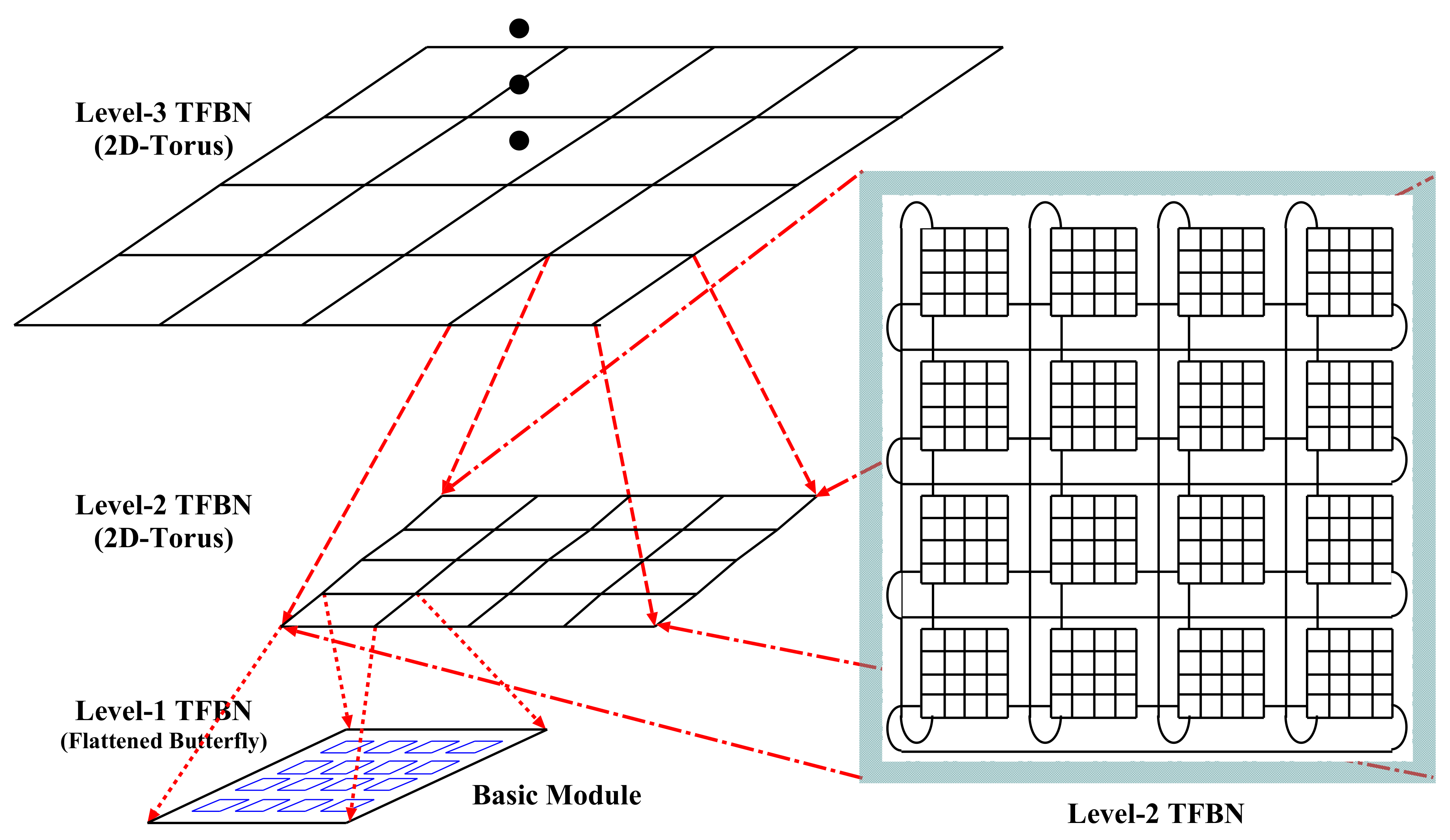
In this research, we have proposed a time-cost effective and high performance and novel hierarchical interconnection network for the next generation MPC system. The proposed HIN consists of numerous basic modules, and these are connected among themselves in a hierarchical manner to form the consequent higher-level networks. The basic modules are a 2D-flattened butterfly network, whereas the higher-level network is a 2D-torus network. The higher-level networks are constructed by considering immediate lower-level networks as a network module and these modules are interconnected as a 2D-torus connection. The proposed HIN is the combination of flattened butterfly network and regular 2D-torus network, and thus it is called the Tori-connected Flattened Butterfly Network (TFBN). We have considered the 2D-torus network for higher-level networks because of its regular connection pattern, and a wrap-around link between end-to-end nodes provides an alternative path to reduce the congestion and contention and increase the throughput. Flattened butterfly networks used as a basic module also reduces the congestion and increases the throughput within the basic module because its many short length links increase the connectivity within the basic module and yield good performance [
27,
28]. The novelty and superiority of the proposed TFBN are assessed by static analysis of static network performance and static time-cost effective analysis.
The preliminary version of a study on TFBN is presented in a conference—some static network performance parameters of TFBN for the Level-2 only consisting of only 256 nodes [
29]. The main objectives of this study are the versatile study of the static performance of networks by evaluating these static network performance parameters for the higher-level network, static cost-effectiveness analysis, and static cost-performance trade-off analysis. The practical acceptance of any interconnection network topology by the industry community depends on the detailed evaluation and analysis of static network performance, cost-effectiveness analysis, dynamic communication performance, fault tolerance performance, on-chip, and off-chip power consumption, computational intensive problem mapping in the network topology, and so forth. In this first step of detail study, we have considered static analysis of network performance, cost-effectiveness as well as cost-performance trade-off.
After the Introduction, the remainder of this article is organized as follows:
Section 2 and
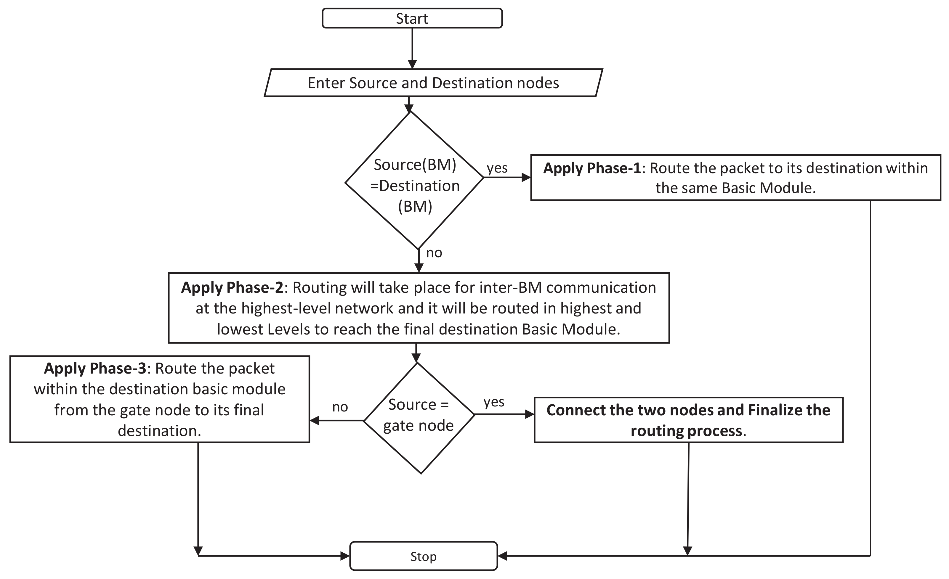
Section 3 discuss the network architecture of the proposed TFBN and the routing of the message within it, respectively. The detailed study of the static network performance of a TFBN is discussed in detail for both the lower level as well as a higher level in
Section 4. The cost-effectiveness as well as the cost performance trade-off factor of this TFBN is analyzed in
Section 5. Finally, the concluding remarks and the future works of this study are presented in
Section 7.
5. Static Cost Effectiveness Analysis of a TFBN
In this article, we have analyzed the proposed TFBN statically to show its superiority over that of other networks. In this section, we have described the studied the cost-effectiveness analysis [
37] of the proposed TFBN to conduct further experiments on dynamic communication performance and the prototype hardware implementation. The parameters included for static cost-effectiveness analysis are static cost, wiring complexity, time-effective factor, cost-effective factor, and cost trade-off factors; these parameters are discussed below.
5.1. Cost
Even though the actual cost of an MPC system depends on its capital expenditure of nodes and their associated links to connect them, the product of the degree of node and network diameter is an acceptable static criterion to assess the cost of an MPC system. The degree of a node is directly proportionate to the cost of the router of a node, and the cost of a node is directly proportional to the cost of an MPC system. Connecting all the nodes by communication links forms the MPC system. The cost of an MPC system inculcating by node degree is to connect the communication links between the nodes to form the MPC system. The diameter of a network is the highest hop distance from the source to the destination using the shortest path algorithm among all distinct source–destination pairs. Therefore, the product of these two parameters named degree and diameter is a wise criterion to compare different interconnection network topologies.
The cost of different networks with two different sizes are estimated and charted in
Table 2. It is presented that the cost of TFBN is lower than all Level-2 hierarchical networks and conventional mesh and torus networks with 256 nodes. However, the TFBN is a little bit costlier than Level-3 hierarchical networks, and much less than conventional mesh and torus networks with 4096 nodes. This slightly high cost incurred due to the high degree of node even though the diameter is quite lower than those hierarchical networks considered in this article.
5.2. Wiring Complexity
The wiring complexity is represented as the number of communication links required for interconnecting entire nodes of an MPC system. It is a static cost estimation for the communication links cost. The communication link cost depends on the length of the links and their underlying interconnection ranging from the VLSI chip level to the board level, cabinet-level, and system level. The chip level designed is ignored here because we have considered our design using node. Therefore, our consideration is from the board level to the system level. In static wiring complexity evaluation, we have considered the number of communication links and not the length of the links. Thus, both the long length link and short length link are considered as an equal cost.
The proposed TFBN consists of numerous basic or primary modules whereby this primary module is a 2D-torus network. The wraps links in these basic modules result in a bit high number of communication links, which is, as mentioned before, the wiring complexity. The wiring complexity of a TFBN is
, where
L is the level number. As tabulated in
Table 2, the wiring complexity of the proposed TFBN is more than that of mesh, torus, TESH, and TTN networks. These extra-short length wrap-around links in the basic module result in short diameter and low average distance.
5.3. Static Cost Performance Trade-off Analysis
Before going to prototype implementation or practical implementation of a huge expensive MPC system, many early stages of evaluation are crucially needed to investigate the suitability of the proposed interconnection network. In this study, we have studied the very first stage of evaluation and statically evaluated the suitability of the proposed TFBN using many static parameters. We have considered many static parameters and the last one is the static cost-performance trade-off factor (CPTF). It is mentioned earlier that the cost incurring parameters of an MPC system is a router in the node (i.e., node degree) and a number of communications links and their total length to layout the system design (i.e., wiring complexity). The most decisive parameter for the static network performance is the diameter; this indicates the upper bound of the communication latency. The diameter again depends on the network size, i.e., the total number of nodes. Considering all these parameters, the CPTF of an interconnection network topology is expressed by the following Equation (
1). The higher the outcome of Equation (
1), the more suitable the interconnection network:
We have assessed the factor of static cost-performance trade-off of TFBN along with TTN, TESH network, 2D-torus, and 2D-mesh networks, and the results are tabulated in
Table 2 for both 256 nodes and 4096 nodes network. It is stated that the CPTF of a TFBN network is far higher than that of Torus, Mesh, TESH, and TTN networks for both sized network (256 nodes and 4096 nodes).
5.4. Cost Effective Factor
A massively parallel computer system is constructed by connecting numerous nodes interconnected using communication links under an interconnection network topology. The major cost of a node is incurred because of its processing elements, router, and memory. Considering the price of communication links or cables in creating an MPC system is also one of the important factors to calculate the actual cost of an MPC system. The price of the wires has a crucial influence on the cost of building MPC systems; therefore, finding a new parameter using the cost of these wires to evaluate these systems is important.
Usually, the parallel computer system is used to reduce the processing time and speed up the operation. The evaluation of the performance of MPC systems takes into account speedup and efficiency to assess these systems. The more nodes that are interconnected together, the more speed that will be attained. In addition, surely the ratio is not linear. The speedup and thus the efficiency of an MPC system depend on the proficient use of the communication links used to interconnect the MPC system.
The cost-effective factor (CEF) is considered as a crucial static parameter to assess the feasibility of an MPC system. This parameter considers the cables count as a function of the processors’ count. Therefore, it denotes
, where
p represents the number of processing elements or cores and
l represents the number of links. The proportion of wires count to nodes count denoted as
. The cost of processing elements is represented as
, and the cost of communication links is represented as
. The parameter
is outlined as the ration between
and
, and
. To evaluate the CEF parameter, we have considered the homogeneous parallel computer systems whereby the cost of processors and cables is maintained as a similar ration. Considering
p,
l,
,
, and
, and
, the CEF of an interconnection network topology is expressed as the following Equation (
2):
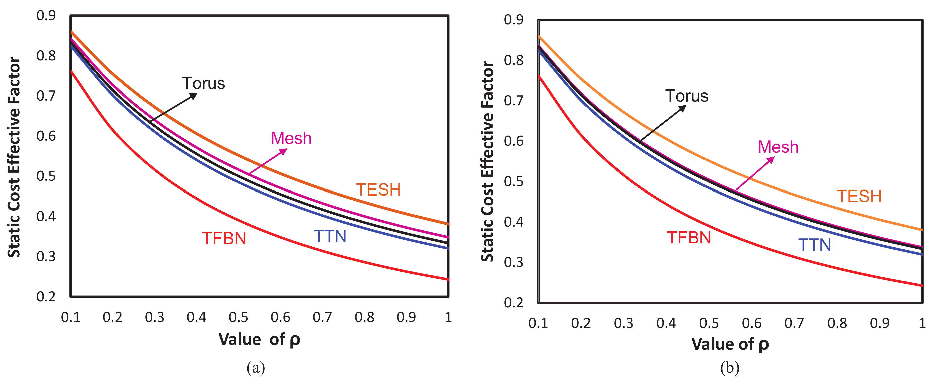
We have assessed time cost-effective factors of TFBN along with the TTN and TESH network, 2D-torus, and 2D-mesh networks for different
ranging from
to
and plotted in
Figure 4. We have considered two different size networks such as 256 nodes and 4096 nodes.
Figure 4a portrayed the CEF of different networks for 256 nodes and
Figure 4b portrayed the same for 4096 nodes. For all the values of
,
, the CEF of TFBN is substantially less than that of TTN, TESH, torus, and mesh networks. From
and onward, the CEF of the TFBN is significantly lower than those networks for both 256 node and 4096 node networks. This proves that TFBN is a profitable network compared to these networks. This qualifies TFBN to be a good choice compared to many conventional and hierarchical interconnection networks to frame future generation supercomputers or MPC systems.
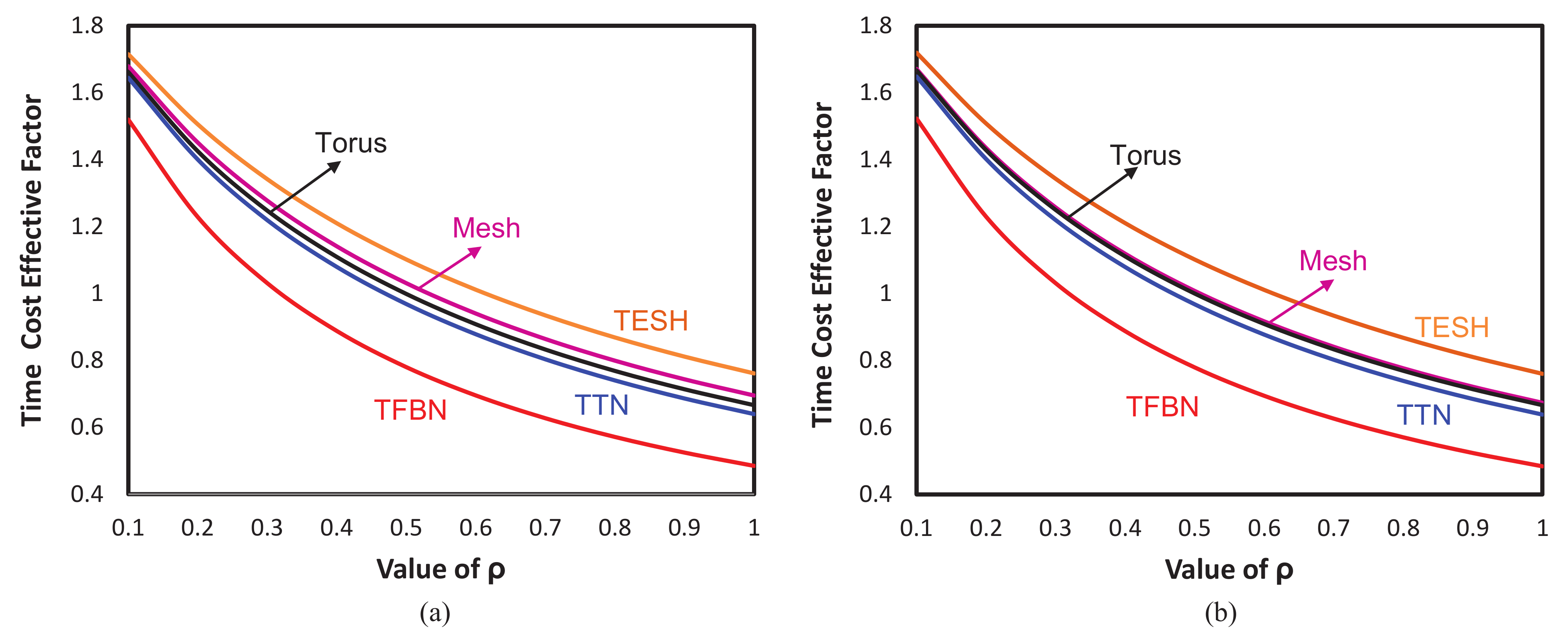
5.5. Time Cost Effective Factor
The main purpose of the use of an MPC system is to solve the computational intensive problem or a grand challenge problem in a reasonably short period of time. This time depends on four factors, viz., the processing speed of an individual node, the dividing of the tasks among the nodes an MPC system and coordination of these tasks between nodes, the underlying routing algorithm to transfer the flits between source and destination nodes, and after the execution of each individual node task merging these individual execution outcomes to conclude with the final result. The fast time implies that the MPC system fast individual node and the underlying interconnection network has good performance in terms of less blocking, delay, and congestion. Thus, time is also an important factor in measuring the efficiency of an MPC system. Cost-effective factors considered along with time factors to determine the time cost-effective factor (TCEF) of an interconnection network. Therefore, the TCEF is a very important and essential parameter to statically assess the feasibility of an MPC system, especially its underlying interconnection network topology. TCEF of an interconnection network is expressed by Equation (
3):
TCEF of a network denotes as
where
p denotes the number of processor in an MPC system, and
denotes time taken to solve a problem using that MPC system.
denotes the time taken to solve the same problem using a single processing element. Here,
and
, whereby
. The values of
and
are constants and considered equal to 1 for considering linear time penalty in
. Including all of these values, Equation (
3) is simplified as below:
We have assessed the time cost-effective factor of TFBN along with TTN, TESH network, 2D-torus, and 2D-mesh networks for different
ranging from
to
and plotted in
Figure 5. Like CEF, here, we have also considered two different size networks such as 256 nodes and 4096 nodes.
Figure 5a depicted the TCEF of different networks for 256 nodes and
Figure 5b depicted the same for 4096 nodes. For all the values of
,
, the TCEF of TFBN is significantly lower than that of TTN, TESH, torus, and mesh networks. From
and onward, the TCEF of the TFBN is expressively lower than those networks for both 256 node and 4096 node networks. This proves that TFBN is a promising hierarchical interconnection network as compared to these networks. This qualifies TFBN to be a plausible alternative choice compared to many conventional and hierarchical interconnection networks to build next-generation supercomputers or MPC systems.
6. Some Generalization
Many interesting applications and grand challenging problems are discussed in the Introduction. To solve those problems, we need an MPC system. In addition, the success of an MPC system heavily depends on the reliable and suitable interconnection network. The reliability and suitability of an interconnection network topology are analyzed and assessed from different points of views for the consideration of its pragmatic realization. The very first step of the evaluation of an interconnection network is the assessment of its graph-theoretic properties known as static network performance. These static network performance parameters revealed whether the proposed interconnection network will result in a good performance or not in other aspects.
For example, node degree indicates the cost of a router used in a node; and each node requires a router. Therefore, the cost of an MPC system depends on the node degree and wiring complexity. The low value of node degree and less wiring complexity clearly indicate the lower manufacturing cost of an MPC system. A low value in the distance parameter such as diameter and average distance indicates the possibility to have good dynamic communication performance. The lower hop distance parameter (low diameter and average distance) results in low latency and high throughput. The actual fault tolerance of an MPC system depends on the reconfiguration and routing with redundant resources. However, the ratio between the arc connectivity and node degree results in the static fault tolerance performance. The higher the ratio, the better the fault-tolerance of that network. The proposed TFBN results in significantly low diameter and average distance and reasonably better fault tolerance with the detriment of high node degree and wiring complexity as compared to other networks considered in this paper. However, the static cost (as portrayed in
Table 2) of the TFBN is lower than that of other networks.
The feasibility and cost-effectiveness analysis are also imperative for the consideration of any new interconnection network topology. Static assessment and evaluation of cost-effectiveness along with the cost-performance trade-off factor without any capital expenditure are the good criteria to compare and contrast any new interconnection network with other contemporary networks [
38]. The better performance in this static evaluation will instigate the next level of investigation for the suitability of the proposed network. As depicted in this paper, the cost-effective factor and time-cost effective factor of the proposed TFBN are lower than all of the networks, especially
and onward. In addition, the cost performance trade-off factor of TFBN is appreciably higher than all the interconnection networks.
The initial investigation instigates us for further exploration of the proposed TFBN; and the static hop distance parameters signify that the dynamic communication performance will also be better in terms of low message latency and high network throughput. However, it seems that TFBN will reveal good performance and will be a good choice for the next generation MPC system to overcome the challenging problem. The only shortcoming is the high wiring complexity. Many short length links in the basic module and their layout in the chip will incur a bit more power consumption. The chip-level layout of these links and the reduction of the capacitive effect between two links can reduce this extra power consumption.
The main concept and contribution in the paper is a new HIN called TFBN and its static network performance and cost-effective performance evaluation. With respect to static network performance and cost effective performance evaluation and analysis, the proposed TFB is superior to other conventional and hierarchical interconnection networks. The open issues and challenges have been mentioned earlier.
The success of an MPC system is how fast and efficiently it can execute and process a complex task, and the time required for this purpose depends on the execution time and communication and coordination time among the nodes. The execution time is constant, and it depends on the number of cores in the processor and its clock cycles. The execution time is fixed for a particular node of an MPC system. Communication time depends on the number of steps for communication and coordination. Therefore, the total required time is proportional to the number of steps required for communication and coordination.
The practical applicability of an interconnection network topology is usually justified by assessing the number of communication and coordination steps required for the benchmark computational intensive problem, viz., fast Fourier transform, solution of a partial differential equation, bitonic merge, finding the maximum, etc. It is believed that the proposed TFBN will result in less communication steps to solve these computational intensive problems because of the low diameter and average distance. A similar phenomenon is observed in our another study [
39].
The implementation of a massively parallel computer system is the integration of many chips in the chip level integration to create a node. The interconnection of many nodes in the board level interconnection to make a board, interconnection of many boards in the cabinet level interconnection is to make a cabinet, and finally interconnection of many cabinets in the system level interconnection is to build the MPC system. In the TFBN, Level 1 (BM) is considered as the board, Level-2 is considered as the cabinet, and Levels 3, 4, and 5 are considered as system level interconnection. As mentioned before, Level-4 is interconnected using Level-3 as a sub-net module and similarly Level-5 is interconnected using Level-4 as a sub-net module. In this research, we have considered the static network performance and static cost effective analysis of the proposed TFBN. This is the very first stage of analysis, and, in the next step of this research, we will evaluate the dynamic communication performance by a flit-level simulator.
7. Conclusions
In this article, we have statically proposed and studied details of the TFBN. The architectural structure of the TFBN has been discussed in detail, and its superiority is depicted by evaluating many static parameters and comparing these parameters with Torus, Mesh, TESH, and TTN networks. The static parameters considered in this paper to show the preeminence of the TFBN are hop distance parameters such as diameter and average distance; connectivity parameters such as node degree, arc connectivity, and bisection width; cost parameter such as cost and wiring complexity; and cost-effectiveness parameters such as cost-effective factor (CEF), time cost-effective factor (TCEF), and cost-performance trade-off factor (CPTF).
Results evaluated of the above parameters revealed that TFBN possesses several attractive features. These include quite a low diameter and average distance, high static fault-tolerant and moderate bisection width, substantially low CEF and TCEF, and significantly high CPTF compared to those of TTN, TESH, torus, and mesh networks. These benefits are attained with the cost of a high node degree and wiring complexity. The flattened butterfly network as a basic module needs a few more short length links which result in the complexity of the wiring of the proposed TFBN being a bit high as compared to other networks considered in this paper. Using these extra links for the interconnection of the basic module in turns increases the node degree. It is shown that this high node degree increased the static cost of the proposed TFBN marginally higher than TTN and TESH networks. However, it is still far lower than the torus and mesh networks. From the cost-performance trade-off analysis, it is divulged that the TFBN is highly cost-effective compared to other networks. Therefore, TFBN will be a promising HIN topology to construct an MPC system that supports exa-scale or zetta-scale computation power.
The proposed TFBN was statically assessed and the performance was analyzed from various points of view. This is the first-stage research on TFBN. There is a long way to go for the consideration of TFBN by the industry community. Even though the diameter and average distance indicate the yielding of high throughput and low latency, evaluation of these two parameters (latency and throughput) has not yet been evaluated yet. Evaluation of these two parameters using a flit level simulator under deterministic dimension order routing and their improvement using adaptive routing algorithms are kept as the immediate next future step of evaluation [
40]. Statically, the TFBN is cost-effective, and its cost performance trade-off is also quite good; however, prototype implementation by FPGA is necessary to assess the actual cost of the proposed TFBN [
41]. The study can be implemented in various application domains such as the IoT enabled smart grid system and evolving ESS technologies.


