Article

Effects of the Mortar Matrix on the Flexural Capacity of Masonry Cross Sections Strengthened with FRCM Materials

by
Giovanni Crisci
1,
Giancarlo Ramaglia
2,
Gian Piero Lignola
3,*,
Francesco Fabbrocino
2 and
Andrea Prota
3
1
Department of Engineering, University of Naples “Parthenope”, Centro Direzionale C4, 80143 Naples, Italy
2
Department of Engineering, Telematic University Pegaso, Piazza Trieste e Trento, 48, 80132 Naples, Italy
3
Department of Structures for Engineering and Architecture, University of Naples Federico II, Via Claudio 21, 80125 Naples, Italy
*
Author to whom correspondence should be addressed.
Appl. Sci. 2020, 10(21), 7908; https://doi.org/10.3390/app10217908
Submission received: 7 October 2020 / Revised: 30 October 2020 / Accepted: 4 November 2020 / Published: 8 November 2020

Abstract

:
The strengthening intervention strategies that exist for masonry buildings are based on the use of thin composites and are a recent activity used in structural engineering. Nowadays, mortar matrices are frequently found instead of epoxy resins, since the fiber reinforced cementitious matrix (FRCM) composites are more compatible with masonry than fiber reinforced plastic (FRP) ones. The mortar matrix in FRCM composites is not comparable to the epoxy resin, and therefore its contribution is different not only in traction but above all on the compression side. Due to its larger thickness, if compared to the epoxy resin, the impact of the mortar matrix on the flexural response of strengthened cross sections is not negligible. This paper aimed to investigate the influence of the contribution of the mortar matrix on the compression side on the flexural capacity of strengthened cross section. As such, p–m interaction domains and bending moment–curvature diagrams were evaluated to understand the influence of several mechanical properties of fiber and mortar matrices on FRCM efficiency, typical of real applications. Hence, the impact of several constitutive relationships of composites (linear and bilinear behavior) was considered for the structural analysis of the strengthened cross section. The presented results are all completely in a dimensionless form; therefore, independent of geometry and mechanical parameters can be the basis for developing standardized design and/or verification methodologies useful for the strengthening systems for masonry elements.

1. Introduction

Nowadays, the use of composites for strengthening intervention and structural rehabilitation of existing masonry buildings is of paramount importance. The last seismic events in Italy, such as L’Aquila (2009), Emilia Romagna (2012), Central Italy (2016), and Ischia (2017), have confirmed the high vulnerability of masonry structures [1,2,3]. This is a crucial point for the Italian regions, where the masonry buildings represent the large part of the existing stock (i.e., churches, historic monuments, residential buildings). Such structures were built according to inadequate codes without seismic criteria. The need to retrofit these buildings today is clearer than before [4,5,6]. In the last few years, new techniques based on the use of fiber reinforced composite materials—i.e., fiber reinforced plastics (FRP) and fiber reinforced cementitious matrix (FRCM)—were developed and studied. The first ones are based on the use of high strength fibers bonded by means of epoxy resin and applied on concrete, steel, masonry, and wooden structural element [7,8,9,10,11]. Pre-formed FRP materials are largely used as well, made of fibers pre-impregnated with resins in the form of a sheet, characterized by initial axial rigidity, and a mono-directional behavior [12] that can be mechanically fastened [13]. These composites could represent the best solution for structural rehabilitation; indeed, they are characterized by a high strength/weight ratio, being successful in increasing the flexural capacity for the structural element without significant increases of mass of structures. For masonry buildings, the use of a mortar matrix (i.e., FRCM) instead of an organic one (i.e., FRP) is preferred. Indeed, cementitious matrices offer better performance under elevated temperatures and better compatibility with modern masonry substrates. In fact, several authors observed good performances in practical applications [14,15,16,17,18,19]. More studies, however, are required to better understand the behavior of composite material on the structural response of strengthened masonry elements [20,21,22], both in terms of flexural [23,24,25] and shear performance [26,27,28].
The calculation models proposed by Italian guidelines CNR–DT 215 [29] and/or internationals codes provide good results for FRP where the contribution of the mortar matrix can be completely neglected. Such assumptions cannot be directly extended to the case of FRCM. Indeed, FRCM, which is also referred to as TRM, i.e., textile reinforced mortar, is composed of a fiber grid with a thickness similar to FRP dry fibers, which is embedded in a mortar matrix with a thickness of about 10–20 mm, i.e., about one order of magnitude higher than FRP organic matrix.
A strengthening system is applied, generally, on the side where the masonry is weaker by its nature, i.e., on the tensile side. Due to the force reversal during seismic actions, the application of reinforcement systems occur on both sides of a masonry panel. Current Italian guidelines [29] not only neglect the contribution of the mortar matrix (on tensile side), leading to FRCM being conflated with FRP, but they disregard the strengthened layer on a compression side, assuming that the composite material is unable to carry loads.
This paper aimed to analyze the impact of the mortar matrix on the flexural capacity of the strengthened cross section (see Figure 1), observing the dimensionless axial load (p) and bending moment (m) interaction domains [30], as well as the ductility capacity through the analysis of the bending moment–curvature diagrams. The results are shown in a dimensionless form. Since they are independent geometrical and mechanical parameters of the masonry and strengthening system, they could represent the basis for the development of design and verification approaches.

2. Materials and Methods

In this section, the constitutive law of the materials (such as masonry and FRCM) adopted for the structural analysis are defined. From the scientific literature, several stress–strain constitutive relationships can be used to describe the mechanical behavior of masonry [31]. One of the most adopted models for compressive behavior, used for the presented analyses, is suggested by CEN Eurocode 6 [32], as shown in Figure 2. This model completely neglects the post-peak softening, considering a perfectly plastic post-peak behavior. The tensile behavior, on the other hand, can be described by elastic–brittle relationship, yet for the purposes of the present work, its contribution is negligible when the strengthening system is applied.
Composite materials are, by definition, made up of two or more materials known as phases. In FRCM composite materials, it is possible to differentiate exactly three phases: the fibrous phase, the mortar matrix phase, and the interface phase. Due to this mixed nature of the mortar matrix and fiber, the FRCM composite is characterized by various phenomena such as matrix cracking, slip, or debonding phenomena. However, it is possible to provide a general stress–strain relationship to simulate the behavior of the whole composite system to interpret the different factors that influence its behavior most. De Felice et al. [33] reported three different stress–strain relationships to simulate the behavior of composite systems in tension: linear, bilinear, and trilinear behavior. For the purposes of this work, only the linear and bilinear behaviors were compared to different behaviors between a classical FRP and FRCM with synthetic fibers, as shown in Figure 3. Moreover, the bilinear and trilinear relationships take into account several effects of the mortar matrix, such as the cracking, bond slip, or tension stiffening effect that are neglected by the linear behavior.
The structural analysis of the strengthened cross section was performed with reference to the p–m interaction domains that allows for the evaluation of the flexural capacity (m) under a specified axial load (p) in the dimensionless format. Indeed, we evaluated the impact of mechanical parameters on the flexural capacity response. The numerical analysis of the cross section is based on the same classic assumptions used for reinforced concrete (RC) cross sections in the technical approach.
  • Conservation of plain sections (also referred to as the Bernoulli–Navier assumption);
  • validity of the Bernoulli principle, wherein the shear deformability is neglected;
  • the stress–strain relationship of the materials is known a priori;
  • the stresses are dependent on the strain of the element alone, so that the effects of viscosity and shrinkage over time are neglected;
  • it is assumed that the application of the load and consequent deformation take place in a monotonous way, and thus they do not explicitly consider the behavior under cyclic loads;
  • it assumes the perfect bond between masonry and the strengthening system (without slip);
  • the ultimate condition of the cross section is reached, either by crushing the compressed masonry or tensile failure of the composite system.
As listed previously, the strengthening system was considered perfectly bonded to the masonry substrate in accordance to several experimental bond tests [34,35], which evidenced that debonding phenomena from the substrate rarely occur for such materials. Bonding with the matrix fiber interface is included in the phenomenological constitutive relationships in tension for the composites.
The construction of p–m interaction domains has considered with a completely dimensionless form. To better understand the dimensionless procedure, we started from translation and rotation equilibrium equations wherein each contribution is in dimensional form. Per usual, from the latter equations, the depth of the neutral axis and the flexural capacity of the strengthened cross section can be defined, as Equations (1) and (2) report:
P = ψ · x · B · f c B · t f · σ f + B · t m o r · σ m o r
M = ψ · x · B · f c · ( b c ) + B · t f · σ f · ( b f ) + B · t m o r · σ m o r · ( b m o r )
According to Figure 4:
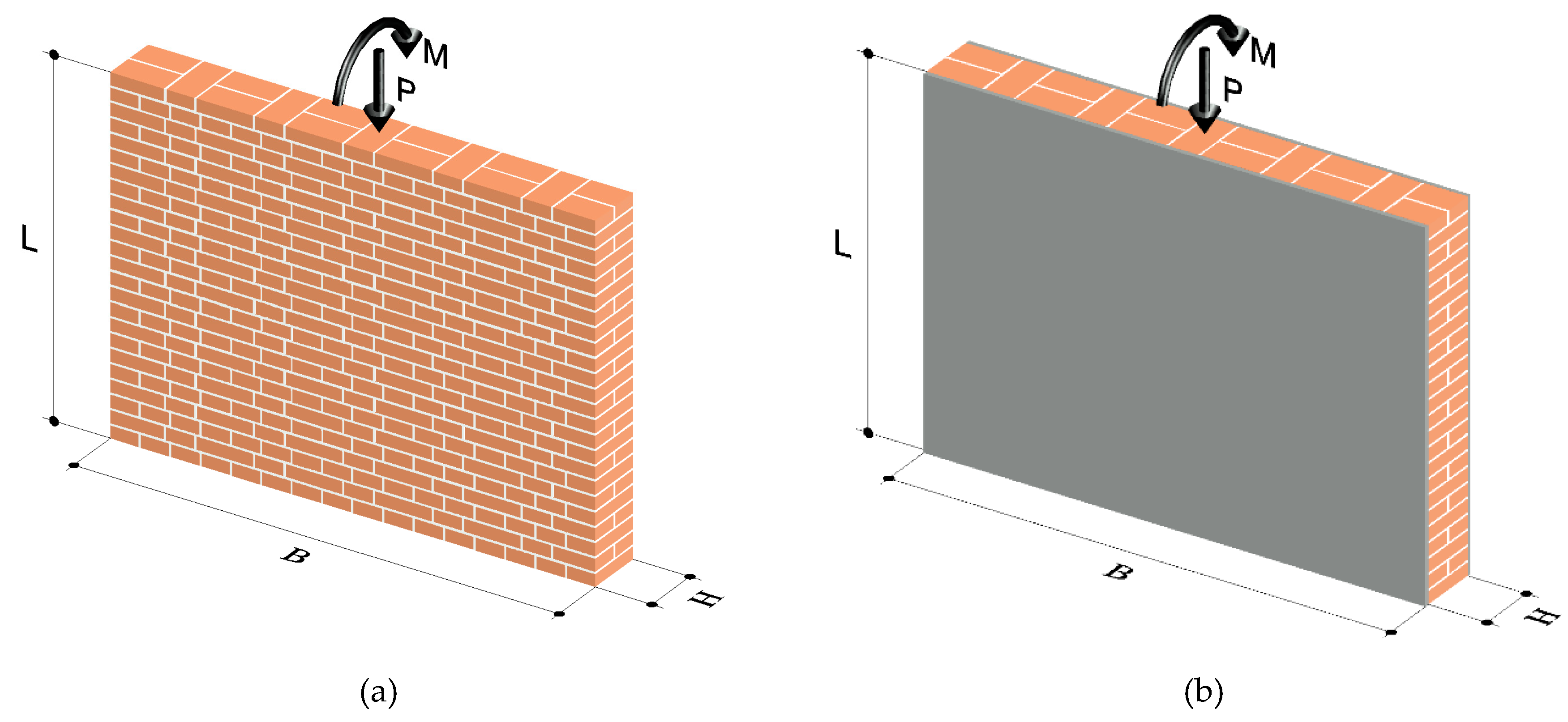
  • P and M are the axial force and the bending moment;
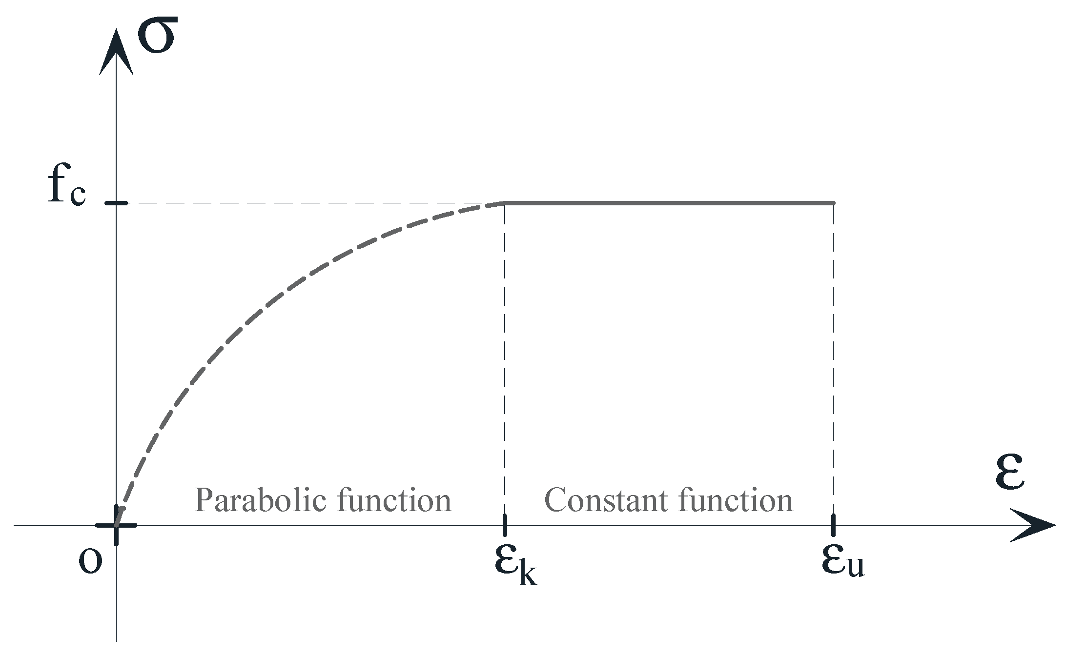
  • fc is the compressive strength of masonry;
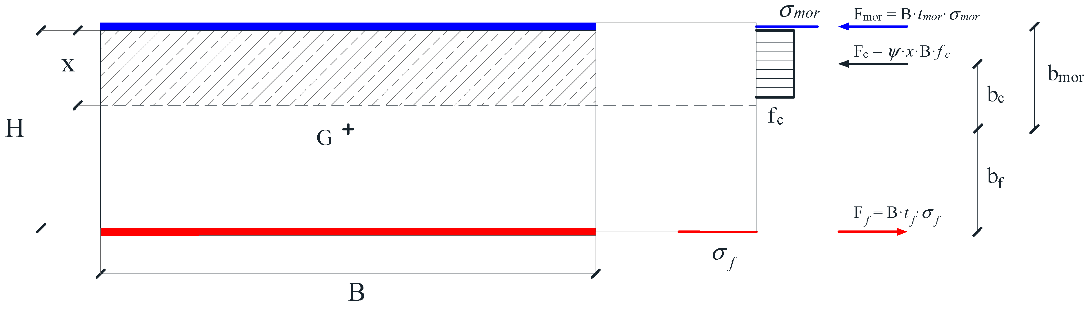
  • σmor and σf are the stress of the mortar matrix on compression side (same relationship of masonry, see Figure 2) and the stress of the composite on tension side, respectively;
  • B and H are the base and the height of the cross section, respectively;
  • tf, tmor are the thickness of fibers and mortar matrix, respectively;
  • bc, bf and bmor are the distances of force resultants from the centroid of cross section, respectively.
The fundamental quantities for the structural analysis of a strengthened cross section were evaluated as dimensionless. Given a generic masonry cross section, the main dimensionless parameters are [23]:
p = P B · H · f c     m = 6 · M B · H · f c
With regard to the strengthening system, different dimensionless procedures were performed for the tensile and compressive sides. In Ramaglia et al. [23], a detailed procedure was presented for the composite material on each tensile side (in red in Figure 4), where its contribution is normalized with reference to its ultimate tensile strength. Conversely, this study presents how the compressive contribution offered by the mortar matrix (in blue in Figure 4) can be normalized. Indeed, it was performed with reference to the ultimate compressive strength of the mortar matrix.
The constitutive relationship of the mortar matrix adopted for numerical analysis was the same as of concrete, i.e., the parabola-rectangle diagram [36]. The behavior of the mortar matrix under compression loads was not far from the concrete loads. The contribution of compressed fibers was neglected, as is usually done for FRP strengthening systems due to their slenderness and low mechanical contribution compared to the mortar matrix in compression.
Manipulating Equations (1) and (2) shows the translation and rotation equilibrium equations of the strengthened cross section, respectively:
P = ψ · x · B · f c A f · σ f + A m o r · σ m o r
M = ψ · x · B · f c · ( b c ) + A f · σ f · ( b f ) + A m o r · σ m o r · ( b m o r )
According to (3), the Equations (4) and (5) can be written in dimensionless form:
p = ψ · ξ ω f · σ f ¯ + ω m · σ m ¯
m = ψ · ξ · ( 3 6 · λ · ξ ) + ( ω f · σ f ¯ + ω m · σ m ¯ ) · ( 3 + 3 · ρ m )
where (see Figure 5):
  • ξ is the depth of neutral axis normalized with reference to cross section height, ξ = x/H;
  • ψ and λ are the coefficients (dimensionless) that correlate to the real non-linear stress distribution to the uniform distribution and the distance of the resultant of real non-linear stress distribution to the neutral axis depth, respectively [37];
  • ωf and ωm are the mechanical fiber reinforcement ratios related to the tensile and the compressive sides respectively, defined as:
    ω f = A f · f f B · H · f c     ω m o r = A m o r · f m o r B · H · f c
    where Af and Amor are the cross section of dry fiber and of mortar matrix respectively, while fmor and ff are the strength of mortar matrix (in compression) and of composite (in tension);
  • ρm is the ratio between the thickness of the mortar and the height of masonry cross section:
    ρ m = t m o r H
  • σ ¯ m and σ ¯ f are the stress of the mortar matrix on the compression side and the stress of the composite on the tensile side, normalized with reference to the compressive strength of the mortar matrix and to the tensile strength of composite, respectively;
The effect of the mortar matrix on the flexural capacity of the strengthened cross section was analyzed in terms of flexural capacity through the p–m interaction domains, considering the influence of different stress–strain relationships of the composite material, as well as observing, at the same time, the structural behavior of the cross section with, or without, the contribution of the compressed mortar matrix.
It is very important, for the safety of the structures after exceptional actions such as earthquakes, to look over the capacity of the structural elements and include post elastic behavior in evaluations. In this way, the structures can exploit their own capacity to dissipate energy produced during earthquakes in a controlled manner and in specific zones of the structures, expressing the desired collapse mode. It is necessary that structures have an adequate “ductility”. As a result, bending moment–curvature diagrams have been developed, highlighting how the ultimate curvature changes as the constitutive relationship of the FRCM composite and the contribution in compression of the mortar matrix varies.
The analyses have been carried out on four different cases in order to highlight, on a purely theoretical basis, the comparison between several strengthening systems. In particular:
(1)
The linear relationship on the tension side and no mortar contribution on the compression side;
(2)
The bilinear relationship on the tension side and no mortar contribution on the compression side;
(3)
The linear relationship on the tension side and no mortar contribution on the compression side;
(4)
The bilinear relationship on the tension side and mortar contribution on the compression side.
In Ramaglia et al. [23], the typical ranges of variation of the individual materials composing a FRCM composite have been identified. As a result, the dimensionless parameters adopted for the analysis have been chosen, which defined two constitutive relationships to strengthen the system. Listed in Table 1, they are as follows:
  • E ¯ f 
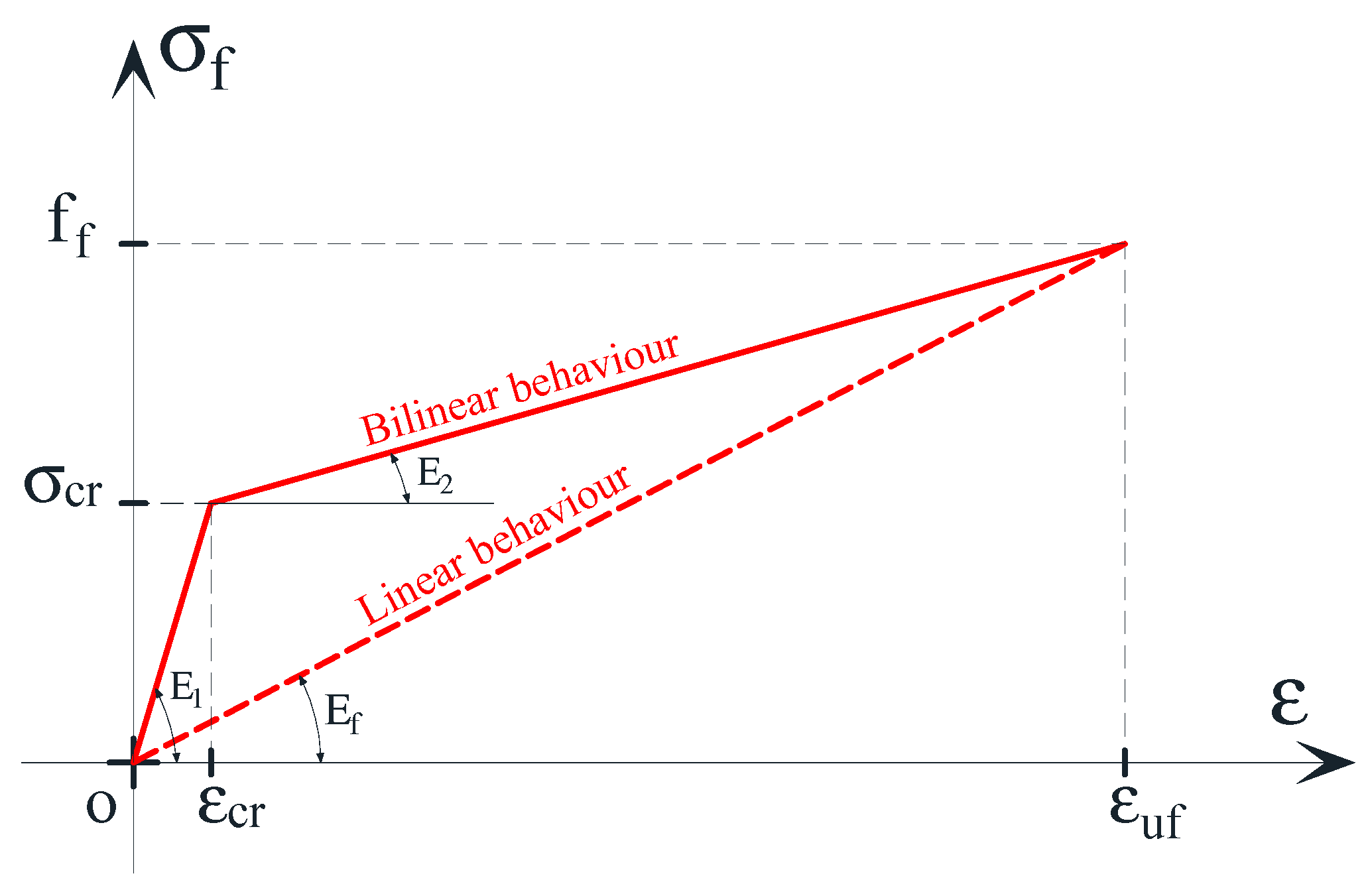
is the normalized modulus of elasticity of the dry fiber (Ef/ff);
  • E ¯ 1 is the normalized uncracked modulus of elasticity of the composite (E1/ff);
  • E ¯ 2 is the normalized post-cracking modulus of the composite (E2/ff);
  • σ ¯ c r is the normalized first cracking strength of the mortar matrix;
  • εuf is the ultimate strain of composite.
The outcomes of the research by Ramaglia et al. [23] allowed us to focus on typical ranges of material properties and, as an example, the properties of a commercial system are adopted and normalized. In Table 1, the normalized parameters are derived from a material, with the mechanical properties outlined in Table 2:
  • Em is the modulus of elasticity of the mortar matrix;
  • σcr is the homogenized first cracking in tension of the mortar matrix [23];
  • Ef is the modulus of elasticity of the dry fiber;
  • E1 is the uncracked modulus of elasticity of the composite homogenized to dry fiber [23] (see Figure 3);
  • E2 is the post-uncracked modulus of elasticity of the composite homogenized to the dry fiber [23] (see Figure 3);
  • εcr is the strain corresponding to the stress σcr.
Figure 6 shows the linear and bilinear behavior according to the values listed in Table 1.
In order to have a good variability of the results, the mechanical compressed mortar matrix reinforcement the ratio (ωm) and mechanical fiber reinforcement ratio (ωf), which varied to define several p–m interaction domains. In this way, the influence the constitutive relationship of other parameters, such as the mechanical reinforcement ratios, were analyzed. Figure 7 shows the numerical results in terms of p–m interaction domains from case 1 to case 4 as the dimensionless parameters ωm and ωf change. The diagrams were grouped to fix the mechanical fiber reinforcement ratio, where ωf was equal to 5%, 10%, and 20% (Figure 7a–c, respectively).
In Figure 7, the comparison between the p–m interaction domains at different mechanical ratios confirmed that the contribution of the mortar matrix played a non-negligible role, as its presence greatly enhanced the axial load capacity during compression and improved the bending capacity of the strengthened cross section. The increase in flexural capacity was mainly related to the mechanical fiber reinforcement ratio ωf. When ωf was relatively low (for example the diagrams in Figure 7a), in the typical working range of masonry structures with a variable p from 0 to 0.4, the increase in flexural capacity was relatively moderate if compared to the case where ωf was higher. Moreover, results shown in Figure 7 confirmed that when the reinforcement ratios for the compression and tension sides were fixed, the different behavior of the stress–strain relationship of the composite, linear, or bilinear relationship provided a reserve of flexural capacity. Such reserve was greater the more ωf increased. It is worth noting that when ωf was smaller than ωm (i.e., in case 4; Figure 7a), it an overlap of the p–m interaction domain at low compression forces can be observed. This is due to failure that occur on the tension side, where the composite material works at its ultimate strain and the influence of the different constitutive relationships is negligible. The failure on tension side tends to reduce when ωm increases.
For higher axial force values, the p–m interaction domain tends to overlap due to the fact that when the strengthened cross section is subjected to large axial forces, the FRCM on the tension side has a low working rate, favoring compressive behavior.
As mentioned before, increasing the flexural capacity of the masonry element is a limited benefit; in a seismic context, it is necessary to ensure that the element also has good performance in post-elastic fields in order to prevent collapse. It is possible to read such information from the bending moment–curvature diagrams (see Figure 8).
In Figure 8, it can be observed that the dimensionless curvature capacity (χH) of the strengthened cross section was clearly affected by the different relationships between the composite materials. When observing cases 1 and 2, it is clear which matches case is reinforced on one side, and which strengthening system increases the flexural capacity reduces the ultimate curvature and ductility. In other words, applying reinforcement only on the tension side tends to weaken the cross section, even though it is related to an increase in flexural capacity. The presence of the mortar matrix in compression conversely causes an increase of flexural capacity and increases the ultimate curvature (see cases 3 and 4). How much curvature can be recovered from the mortar matrix is to the mechanical fiber reinforcement ratio ωf. As such, the higher ωf is, the smaller the ultimate curvature is (see Figure 8), and thus the higher ωm is needed to recover the lost curvature capacity.
As observed in the p–m interaction domains, the different relationships adopted for the composite material on the tension side provides different results in terms of ultimate curvature. In fact, a not already cracked mortar matrix (bilinear constitutive relationship) provides a greater result if compared to the one provided by the linear relationship. Such different behavior yields to a reduction in the ultimate curvature due to an increase in the neutral axis depth.
It is also interesting to observe how the ultimate curvature changes with the axial load for several specified cases (Figure 9). In cases where the strengthened cross section is characterized by a failure on the compression side—i.e., cases 1 and 2 (Figure 9a,b)—a continuous reduction of the ultimate curvature and ductility is observed. Conversely, initial increases of ultimate curvature, with the increase of the axial load in lower value ranges, are related to the cases with a failure on the tension side and the peak, with subsequent reduction representative of a transition, i.e., from “failure on tension side” to “failure on compression side”.
The analyses performed in the present work are based on a purely numerical approach. In order to validate the procedure proposed, we conducted a comparison with the specimens and materials experimentally tested by Papanicolaou et al. [38]. Based on the four previously defined cases, bending moment–curvature diagrams were evaluated according to experimental data, as shown in Figure 10. Table 3 and Table 4 show the dimensional and dimensionless parameters from Papanicolaou et al. [38].
Figure 10 shows the bending moment–curvature diagrams built with dimensionless parameters from Papanicolaou et al. [38]. Small increases occurred for cases 2 and 4, especially when compared to cases 1 and 3. These increases depended on the adopted mechanical parameters, wherein the Young’s modulus Em of the mortar matrix (630 MPa) was rather low, and the bilinear behavior was linear.
The comparison between numerical and experimental values is shown in Figure 11. It is worth noting that the cases 1 and 2 represent the cross section reinforced on both sides and on tensile side, respectively. Figure 11 does not highlight a clear and simple comparison, but, above all, it clarifies what this work has proposed. It is very clear that case 2 (i.e., cross section reinforced only on the tension side) has a significantly lower capacity compared to the experimental data. On the other hand, case 1 (i.e., cross section reinforced on both sides, in particular the case with axial load p = 0.10) is in perfect agreement with the experimental value. Therefore, the presence of the mortar matrix in compression played a fundamental role in order not to excessively underestimate the flexural capacity of the strengthened masonry structural elements.
It is worth underlining that the comparison was made with reference to a limited number of samples. Given the particular nature of the materials, the imperfect match with the experimental thresholds could be caused by experimental uncertainties during the test, which are not taken into account in the proposed numerical simulation. Certainly, the reliability of the model presented in this paper can be further validated by comparing the analytical results with further available experimental data.

3. Conclusions

The paper focused on the behavior of masonry cross sections strengthened with composite materials such as FRP or FRCM. The structural performance of strengthened cross section was evaluated via varying tensile behaviors in the composite and analyzing the contributions offered by the mortar matrix in the compression. As mentioned, this sought to remark upon the importance of considering the mortar matrices contributions vis-à-vis the tensile and compression sides to preventing excessive underestimation of the structural capacity. The presented results were in a dimensionless form and were valid for mechanical and geometric parameters, thus providing extremely useful results for the design and verification of strengthening interventions. The flexural capacity was evaluated in terms of p–m interaction domains by changing the constitutive relationship of the FRCM. The strengthening system, even if only applied on the tensile side, provided clear benefits to the flexural capacity, causing a reduction in the ultimate curvature. Being able to preserve a plastic capacity reserve was useful for seismic behavior. For this reason, the contribution of the mortar matrix in compression played a major role. It was able to increase not only the flexural and axial capacity but also to provide a good recovery of the ultimate curvature and ductility, as was observed from bending moment–curvature diagrams. Moreover, the analysis of the axial load-ultimate curvature diagrams provided very useful results. It was possible to observe the trend of the ultimate curvature as the mechanical dimensionless parameters and the axial load change. The benefits offered from the mortar matrix in compression was clear in this study. Lastly, depending on the mechanical fiber reinforcement ratio, the ultimate curvature was almost always larger than the unreinforced cross section strengthened only on one side.

Author Contributions

Conceptualization, G.P.L. and A.P.; formal analysis and investigation, G.C. and G.R.; methodology, F.F. and G.P.L.; writing—original draft, G.C. and G.R.; writing—review and editing, F.F. and G.P.L.; supervision, A.P. All authors have read and agreed to the published version of the manuscript.

Funding

This research was funded by the Italian ReLUIS project (Italian Department of the Civil Protection–years 2019–2021).

Conflicts of Interest

The authors declare no conflict of interest

List of Symbols

fccompressive strength of masonry
εkconventional yielding strain of masonry in compression
εuconventional ultimate strain of masonry in compression
σcrfirst cracking in tension of the mortar matrix
fftensile strength of the composite
εcrstrain corresponding to the stress σcr
εufultimate strain of the composite
fmorcompressive strength of mortar matrix
Ecmodulus of elasticity of the masonry
Emmodulus of elasticity of the mortar matrix
Efmodulus of elasticity of the dry fiber
E1uncracked modulus of elasticity of the composite
E2post- uncracked modulus of the composite system
E ¯ f normalized modulus of elasticity of the dry fiber
E ¯ 1 normalized uncracked modulus of elasticity of the composite
E ¯ 2 normalized post- uncracked modulus of elasticity of the composite
σ ¯ c r normalized first cracking stress in tension of the mortar matrix
σ ¯ f normalized stress of the composite system
Amcross section of mortar matrix
Afcross section of dry fiber
Bbase of the cross section
Hheight of the cross section
Paxial load
pnormalized axial load P
Mbending moment
mnormalized bending moment M
tfequivalent thickness of fibers
tmorthickness of mortar matrix
bclever arm of masonry resultant
bflever arm of FRCM resultant
bmorlever arm of mortar matrix resultant
ψdimensionless factor that correlates real nonlinear stress distribution with stress block resultant
λdimensionless factor that correlates real distance of centroid of nonlinear stress distribution with the neutral axis depth
xdepth of the neutral axis
ξnormalized neutral axis
ωfmechanical fiber reinforcement ratio
ωmmechanical compressed mortar matrix reinforcement ratio
ρmratio between the thickness of the mortar matrix and the height of masonry cross section

References

  1. Formisano, A. Theoretical and Numerical Seismic Analysis of Masonry Building Aggregates: Case Studies in San Pio Delle Camere (L’Aquila, Italy). J. Earthq. Eng. 2017, 21, 227–245. [Google Scholar] [CrossRef] [Green Version]
  2. Chieffo, N.; Formisano, A. Induced seismic-site effects on the vulnerability assessment of a historical centre in the molise Region of Italy: Analysis method and real behaviour calibration based on 2002 earthquake. Geosciences 2020, 10, 21. [Google Scholar] [CrossRef] [Green Version]
  3. Salzano, P.; Casapulla, C.; Ceroni, F.; Prota, A. Seismic Vulnerability and Simplified Safety Assessments of Masonry Churches in the Ischia Island (Italy) after the 2017 Earthquake. Int. J. Archit. Herit. 2020. [Google Scholar] [CrossRef]
  4. Acito, M.; Magrinelli, E.; Milani, G.; Tiberti, S. Seismic vulnerability of masonry buildings: Numerical insight on damage causes for residential buildings by the 2016 central Italy seismic sequence and evaluation of strengthening techniques. J. Build. Eng. 2020, 28, 101081. [Google Scholar] [CrossRef]
  5. Alecci, V.; De Stefano, M.; Focacci, F.; Luciano, R.; Rovero, L.; Stipo, G. Strengthening masonry arches with lime-based mortar composite. Buildings 2017, 7, 49. [Google Scholar] [CrossRef] [Green Version]
  6. Chieffo, N.; Formisano, A.; Miguel Ferreira, T. Damage scenario-based approach and retrofitting strategies for seismic risk mitigation: An application to the historical Centre of Sant’Antimo (Italy). Eur. J. Environ. Civ. Eng. 2019, 2116–7214. [Google Scholar] [CrossRef]
  7. Task Group 9.3. Externally bonded FRP Reinforcement for RC Structures; Technical Report, fib Bulletin 14; International Federation for Structural Concrete: Lausanne, Switzerland, 2001.
  8. Teng, J.G.; Chen, J.F.; Smith, S.T.; Lam, L. FRP Strength-Ened RC Structures; Wiley: London, UK, 2002. [Google Scholar]
  9. Council of National Research (CNR). Guide for the Design and Construction of Externally Bonded FRP Systems for Strengthening Existing Structures—Materials, RC and PC Structures, Masonry Structures; CNR-DT 200 R1; CNR: Rome, Italy, 2013. [Google Scholar]
  10. Council of National Research (CNR). Guidelines for the Design and Construction of Externally Bonded FRP Systems for Strengthening Existing Structures—Timber Structures; CNR-DT 201; CNR: Rome, Italy, 2005. [Google Scholar]
  11. Council of National Research (CNR). Guidelines for the Design and Construction of Externally Bonded FRP Systems for Strengthening Existing Structures—Metallic structures; CNR-DT 202; CNR: Rome, Italy, 2005. [Google Scholar]
  12. Salzano, P.; Bonati, A.; Ceroni, F.; Crisci, G.; Franco, A.; Occhiuzzi, A. Statistical analysis on mechanical properties of FRP materials for structural strengthening. In Proceedings of the 7th ECCOMAS Thematic Conference on Computational Methods in Structural Dynamics and Earthquake Engineering, Crete, Greece, 24–26 June 2019; Papadrakakis, M., Fragiadakis, M., Eds.; COMPDYN: Crete, Greece, 2019; pp. 5153–5168. [Google Scholar]
  13. Nardone, F.; Lignola, G.P.; Prota, A.; Manfredi, G.; Nanni, A. Modeling of flexural behavior of RC beams strengthened with mechanically fastened FRP strips. Compos. Struct. 2011, 93, 1973–1985. [Google Scholar] [CrossRef]
  14. Parisi, F.; Lignola, G.P.; Augenti, N.; Prota, A.; Manfredi, G. Rocking response assessment of in-plane laterally-loaded masonry walls with openings. Eng. Struct. 2013, 56, 1234–1248. [Google Scholar] [CrossRef]
  15. Lignola, G.P.; Angiuli, R.; Prota, A.; Aiello, M.A. FRP confinement of masonry: Analytical modeling. Mater. Struct. 2014, 47, 2101–2115. [Google Scholar] [CrossRef]
  16. Carozzi, F.G.; Bellini, A.; D’Antino, T.; de Felice, G.; Focacci, F.; Hojdys, L. Experimental investigation on tensile and shear bond properties of Carbon-FRCM composites applied on masonry substrates. Compos. Part B 2016, 128, 100–119. [Google Scholar] [CrossRef]
  17. Ramaglia, G.; Lignola, G.P.; Fabbrocino, F.; Prota, A. Impact of natural fibers on the ultimate behaviour of masonry elements. In Proceedings of the AIMETA 2017—Proceedings of the 23rd Conference of the Italian Association of Theoretical and Applied Mechanics, Salerno, Italy, 4–7 September 2017. [Google Scholar]
  18. Kouris, L.A.S.; Triantafillou, T.C. State-of-the-art on strengthening of masonry structures with textile reinforced mortar (TRM). Constr. Build. Mater. 2018, 188, 1221–1233. [Google Scholar] [CrossRef]
  19. Crisci, G.; Ceroni, F.; Lignola, G.P. Comparison between Design Formulations and Numerical Results for In-Plane FRCM-Strengthened Masonry Walls. Appl. Sci. 2020, 10, 4998. [Google Scholar] [CrossRef]
  20. Garmendia, L.; San-José, J.T.; García, D.; Larrinaga, P. Rehabilitation of masonry arches with compatible advanced composite material. Constr. Build. Mater. 2011, 25, 4374–4385. [Google Scholar] [CrossRef]
  21. Gattesco, N.; Boem, I. Experimental and analytical study to evaluate the effectiveness of an in-plane reinforcement for masonry walls using GFRP meshes. Constr. Build. Mater. 2015, 88, 91–104. [Google Scholar] [CrossRef]
  22. Ramaglia, G.; Lignola, G.P.; Fabbrocino, F.; Prota, A. Numerical investigation of masonry strengthened with composites. Polymers 2018, 10, 334. [Google Scholar] [CrossRef] [Green Version]
  23. Ramaglia, G.; Fabbrocino, F.; Lignola, G.P.; Prota, A. Unified Theory for Flexural Strengthening of Masonry with Composites. Materials 2019, 12, 680. [Google Scholar] [CrossRef] [Green Version]
  24. Fabbrocino, F.; Ramaglia, G.; Lignola, G.P.; Prota, A. Ductility-based incremental analysis of curved masonry structures. Eng. Fail. Anal. 2019, 97, 653–675. [Google Scholar] [CrossRef]
  25. D’Ambra, C.; Lignola, G.P.; Prota, A.; Sacco, E.; Fabbrocino, F. Experimental performance of FRCM retrofit on out-of-plane behaviour of clay brick walls. Compos. Part B Eng. 2018, 148, 198–206. [Google Scholar] [CrossRef]
  26. Babaeidarabad, S.; De Caso, F.; Nanni, A. URM walls strengthened with fabric reinforced cementitious matrix composite subjected to diagonal compression. J. Compos. Constr. 2013, 18, 04013045. [Google Scholar] [CrossRef]
  27. Ferretti, F.; Ferracuti, B.; Incerti, A.; Mazzotti, C. Diagonal Compression Tests on Masonry Panels Strengthened by FRP and FRCM. In Structural Analysis of Historical Constructions; Van Balen, K., Verstrynge, E., Eds.; CRC Press/Balkema: Boca Raton, FL, USA, 2016; pp. 1069–1076. [Google Scholar]
  28. Crisci, G.; Ceroni, F.; Lignola, G.P. Efficiency of FRCM Systems for Strengthening of Masonry Walls. In Proceedings of the 17th International Conference of Numerical Analysis and Applied Mathematics, Rhodes, Greece, 23–28 September 2019. [Google Scholar]
  29. CNR-DT 215. Guide for the Design and Construction of Externally Bonded Fibre Reinforced Inorganic Matrix Systems for Strenghtening Existing Structures; Council of National Research: Rome, Italy, 2018. [Google Scholar]
  30. Lignola, G.P.; Flora, A.; Manfredi, G. Simple method for the design of jet grouted umbrellas in tunneling. J. Geotech. Geoenviron. Eng. 2008, 134, 1778–1790. [Google Scholar] [CrossRef]
  31. Lourenço, P.B. Experimental and Numerical Issues in the Modelling of the Mechanical Behaviour of Masonry; CIMNE: Barcelona, Spain, 1998. [Google Scholar]
  32. CEN Eurocode 6—Design of Masonry Structures. In Part 1-1: General Rules for Reinforced and Unreinforced Masonry Structures; British Standards Institution: London, UK, 2005.
  33. De Felice, G.; Aiello, M.A.; Caggegi, C.; Ceroni, F.; De Santis, S.; Garbin, E.; Gattesco, N.; Hojdys, Ł.; Krajewski, P.; Kwiecien, A.; et al. Recommendation of RILEM Technical Committee 250-CSM: Test method for Textile Reinforced Mortar to substrate bond characterization. Spring Mater. Struct. 2018, 51, 95. [Google Scholar] [CrossRef]
  34. Bilotta, A.; Ceroni, F.; Nigro, E.; Pecce, M. Experimental tests on FRCM strengthening systems for tuff masonry elements. Constr. Build. Mater. 2017, 138, 114–133. [Google Scholar] [CrossRef]
  35. Bilotta, A.; Ceroni, F.; Lignola, G.P.; Prota, A. Use of DIC technique for investigating the behavior of FRCM materials for strengthening masonry elements. Compos. Part B 2017, 129, 251–270. [Google Scholar] [CrossRef]
  36. CEN Eurocode 2—Design of Concrete Structures-Part 1-1: General Rules and Rules for Buildings; British Standards Institution: London, UK, 2004.
  37. Lignola, G.P.; Giamundo, V.; Prota, A.; Cosenza, E. A unified theory for RC cross sections up to ultimate load, including hardening or softening of concrete. In Proceedings of the 4th Fib Congress 2014, Mumbai, India, 10–14 February 2014; pp. 134–193. [Google Scholar]
  38. Papanicolaou, C.G.; Triantafillou, T.C.; Papathanasiou, M.; Karlos, K. Textile reinforced mortar (TRM) versus FRP as strengthening material of URM walls: Out-of-plane cyclic loading. Mater. Struct. 2008, 41, 143–157. [Google Scholar] [CrossRef]
Figure 1. (a) Unreinforced masonry panel; (b) strengthened masonry panel with fiber reinforced cementitious matrix (FRCM) composite.
Applsci 10 07908 g001
Figure 2. Stress–strain relationships of the masonry.
Applsci 10 07908 g002
Figure 3. Different stress–strain constitutive relationships for composite systems in tension.
Applsci 10 07908 g003
Figure 4. Equilibrium of strengthened masonry section including the effect of mortar matrix of the composite in compression–dimensional form.
Applsci 10 07908 g004
Figure 5. Equilibrium of the strengthened masonry section including the effect of the mortar matrix of the composite in compression–dimensionless form.
Applsci 10 07908 g005
Figure 6. Stress–strain constitutive relationship of composite in tension, adopted for the analyses.
Applsci 10 07908 g006
Figure 7. The p–m interaction domains for all 4 cases: (a) ωf is fixed (5%); (b) ωf is fixed (10%); (c) ωf is fixed (20%).
Applsci 10 07908 g007aApplsci 10 07908 g007b
Figure 8. Bending moment–curvature diagrams for all 4 cases: (a) ωf is fixed (5%); (b) ωf is fixed (10%); (c) ωf is fixed (20%).
Applsci 10 07908 g008
Figure 9. Axial load-ultimate curvature diagrams for all 4 cases: (a) ωf is fixed (5%); (b) ωf is fixed (10%); (c) ωf is fixed (20%).
Applsci 10 07908 g009
Figure 10. Numerical bending moment–curvature diagrams.
Applsci 10 07908 g010
Figure 11. Comparison between numerical bending moment–curvature diagrams and experimental values.
Applsci 10 07908 g011
Table 1. Normalized parameters adopted for the analyses.
ĒfĒ1Ē2 σ ¯ c r εuf
[-][-][-][-][-]
16.6750012.610.250.06
Table 2. Dimensional parameters for the analyses.
EfffEmσcrtftmorE1E2
[GPa][MPa][MPa][MPa][mm][mm][GPa] [GPa]
36215010415380.0220107727
Table 3. Dimensional parameters, adapted from Papanicolaou et al. [38].
Adopted Dimensional Parameters
fcffEmσcrfmorAfEfAmor
[MPa][MPa][MPa][MPa][MPa][mm2][GPa][mm2]
4.3335063083631.3618.8225800
Table 4. Dimensionless parameters, adapted from Papanicolaou et al. [38].
Adopted Dimensionless Parameters
E1/ffE2/ffεcrεufωfωmρm
[-][-][-][-][-][-][-]
75.264.90.0030.014890.430.170.024
Publisher’s Note: MDPI stays neutral with regard to jurisdictional claims in published maps and institutional affiliations.

