Article

Quantitative Demonstration of Wear Rate and Dissipation Energy during Tension–Torsion Cyclic Loading of Steel Wires with Fretting Contact in Different Environmental Media

School of Mechatronic Engineering, China University of Mining and Technology, Xuzhou 221116, China
*
Author to whom correspondence should be addressed.
Appl. Sci. 2020, 10(18), 6610; https://doi.org/10.3390/app10186610
Submission received: 16 August 2020 / Revised: 15 September 2020 / Accepted: 15 September 2020 / Published: 22 September 2020
(This article belongs to the Section Mechanical Engineering)

Abstract

:
The wear rate and dissipation energy during tension–torsion cyclic loading of steel wires with fretting contact in different environmental media were explored in this study. Hysteresis loops of tangential force versus displacement amplitude (Ft-D) and torque versus torsion angle (T-θ), and their dissipation energies were obtained employing the self-made test rig. Morphologies of wear scars of steel wires were observed employing the white light interference surface morphology. The quantitative demonstration of the coefficient of cyclic wear of steel wire was carried out combining polynomial fitting, reconstruction of three-dimensional geometric model of wear scar and Archard’s equation. The results show that Ft-D curves reveal both decreases of the relative slip and dissipation energy in the order: corrosive media, deionized water and air. Increases of contact load and crossing angle caused overall decreases in the relative slip and dissipation energy, while the relative slip and dissipation energy both increased with increasing torsion angle. T-θ curves indicated the largest and smallest dissipation energies in cases of acid solution and deionized water, respectively. Increases of contact load, crossing angle and torsion angle caused increases in relative slip and dissipation energy due to cyclic torsional loading with fretting contact. The wear coefficient in cases of distinct environmental media decreased in this order: air, corrosive media and deionized water. Increases of the contact load, torsion angle and crossing angle all induced increases in the wear coefficient.

1. Introduction

In China, 53% of coal resources are buried below several kilometers [1]. The multi-rope friction hoisting system is widely employed in the kilometer-deep coal mine. During hoisting, the hoisting ropes (twisted by strands and steel wires) are subjected to cyclic stretching, torsional and bending loads, which causes a torsion cyclic loading of steel wires with fretting contact [2]. Besides, the hoisting rope is exposed to alternating environmental media, i.e., air and mine water (PH = 3.0–9.5 [3]), attributed to the rope running cyclically between underground and the ground surface. Therefore, the combined roles of tension–torsion cyclic loading and environmental media cause the material loss of wire cross-section and the induced wire fracture [4], which easily causes rope failure and thus significantly affects the hoisting safety. It is clearly seen that the service life of hoisting rope is greatly affected by the wear rate of steel wire, and the wear rate is closely correlated with the dissipation energy. Therefore, in order to estimate the endurance life of hoisting rope, it is important to quantitatively demonstrate the wear rate and dissipation energy during tension–torsion cyclic loading of steel wires with fretting contact in different environmental media.
Many researchers have carried out research on cyclic tensile loading with fretting contact of steel wires. Llavori et al. [5] explored the effect of crossing angle on the tangential force between steel wires by employing the self-made modular fretting fatigue and fretting wear tribotester and found that there were no non-Coulomb behaviors at low crossing angles. Takeuchi and Waterhouse [6] explored fretting-corrosion fatigue behaviors of steel wires in air and artificial seawater. They found that fretting in seawater seriously reduces the fatigue life at stresses below the fatigue limit in air; cathodic protection restores the fatigue strength to a value greater than that in air. Wang et al. [4,7] analyzed roles of corrosive media and strain ratio on wear and fatigue fracture mechanisms during fretting fatigue. Périer et al. [8,9] studied effects of corrosive media (water and NaCl) on fretting fatigue characteristics of steel wires in bridge cable. Cruzado et al. [10] carried out fretting wear tests of steel wires and predicted the fatigue life of fretted wires. He also found the prediction methodology correctly predicts the life reduction of steel wire with increasing normal contact load. Winkler et al. explored the fretting fatigue behavior of tensioned steel monostrand and quantified the bending stiffness and relative displacement between adjacent layer wires along the length of monostrand [11]. Wokem et al. proposed that fretting fatigue failure often occurred in the cable bent over sheaves and presented empirical equations of fatigue life of the cable [12]. Considering the tension–torsion cyclic loading of steel wires with fretting contact, Wang et al. [3] explored wear mechanisms and crack propagations of steel wires under tension–torsion fretting-fatigue with different tribo-fatigue parameters and corrosive media. According to effects of surface condition, residual stress, material loss at the cross-section, contact pressure, lubricants and additional bending on fretting damage behaviors of steel wires, Liu et al. [13] studied fretting corrosion wear behaviors of steel wires in the alkaline solution and found tuberous fretting wear debris was beneficial to reduce fretting corrosion wear of steel wires. Nakamura et al. [14] investigated mechanical properties and remaining strength of corroded bridge wires. He found that the uneven surface roughness of corroded wires decreased the ductility of corroded wires and thought that the fracture of wires was attributed to mixed effects of corrosion, cyclic stresses, high residual stresses, hydrogen and fretting. Smallwood and Waterhouse [15] explored effects of residual stress patterns on fretting-corrosion-fatigue behaviors of steel wires in seawater and found that the fretting behavior is influenced by residual stresses at points of contact varying around the circumference of the wire. Wang et al. [16] discussed the effects of fretting wear depth and contact load on stress distributions and crack initiation characteristics on fretting contact surfaces of fretted wires and found that increasing wear depth and contact load induces distinct stress distributions and accelerates crack initiation on fretting surfaces. Urchegui et al. [17] analyzed effects of contact pressure, relative humidity and lubricants on the fretting wear behavior in thin steel roping wires. Bonneric et al. [18] dealt with fatigue damage evolution in steel cables used in tires when subjected to cyclic bending loadings and simulated bent cable and its matrix with and without broken wires in order to evaluate the impact of the first breakage on the stress distribution within the cable. Generally speaking, previous efforts mainly focus on failure mechanisms of steel wires during cyclic tensile loading with fretting contact in different environmental media, wear mechanisms and fatigue crack propagations of steel wires during tension–torsion cyclic loading in different environmental media, and effects of surface condition, residual stress, material loss at the cross-section, contact pressure, lubricants and additional bending on fretting damage behaviors of steel wires. However, during tension–torsion cyclic loading of steel wires with fretting contact in distinct environmental media, quantitative demonstrations of wear rate and dissipation energy of steel wires have not been reported yet.
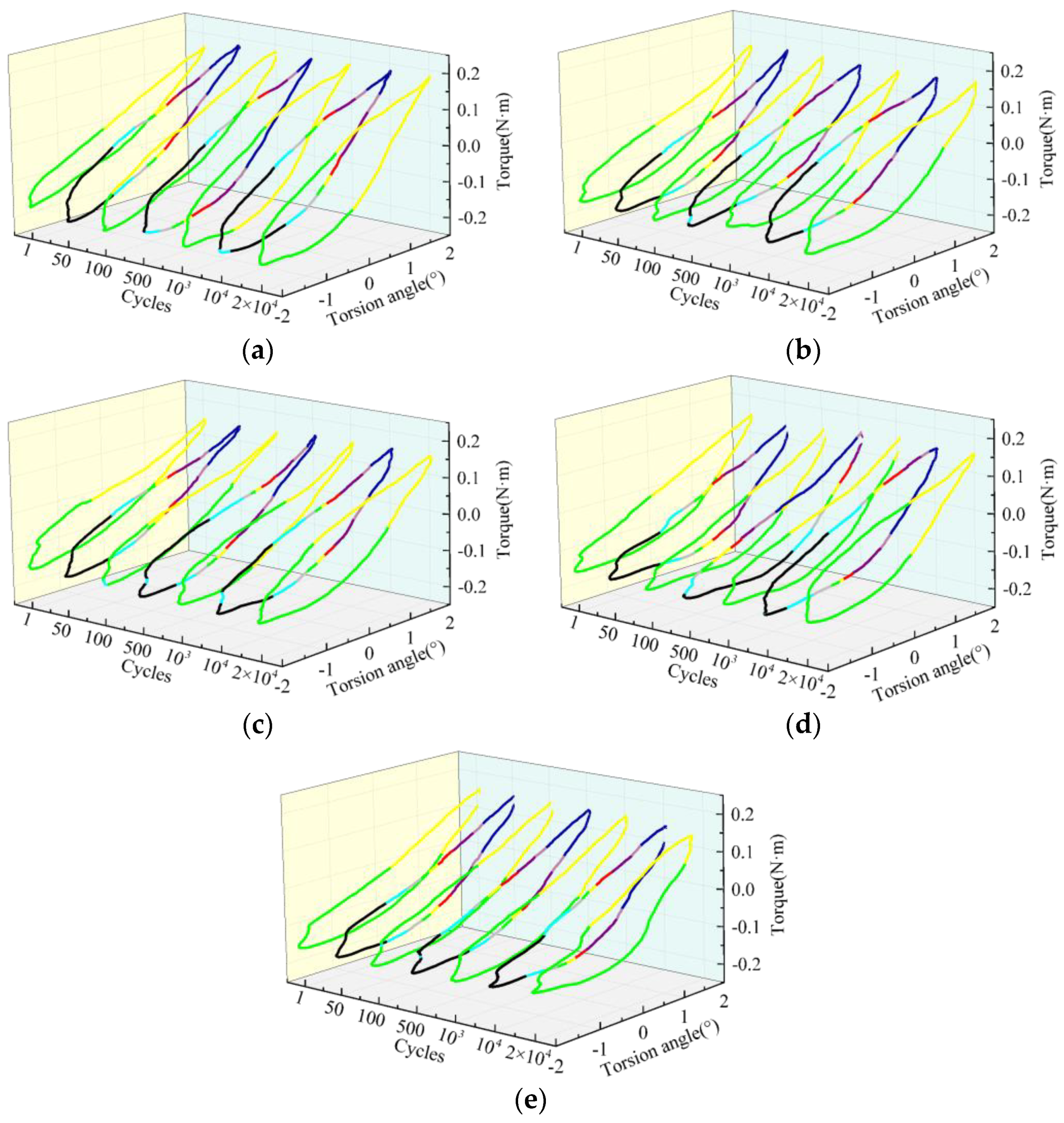
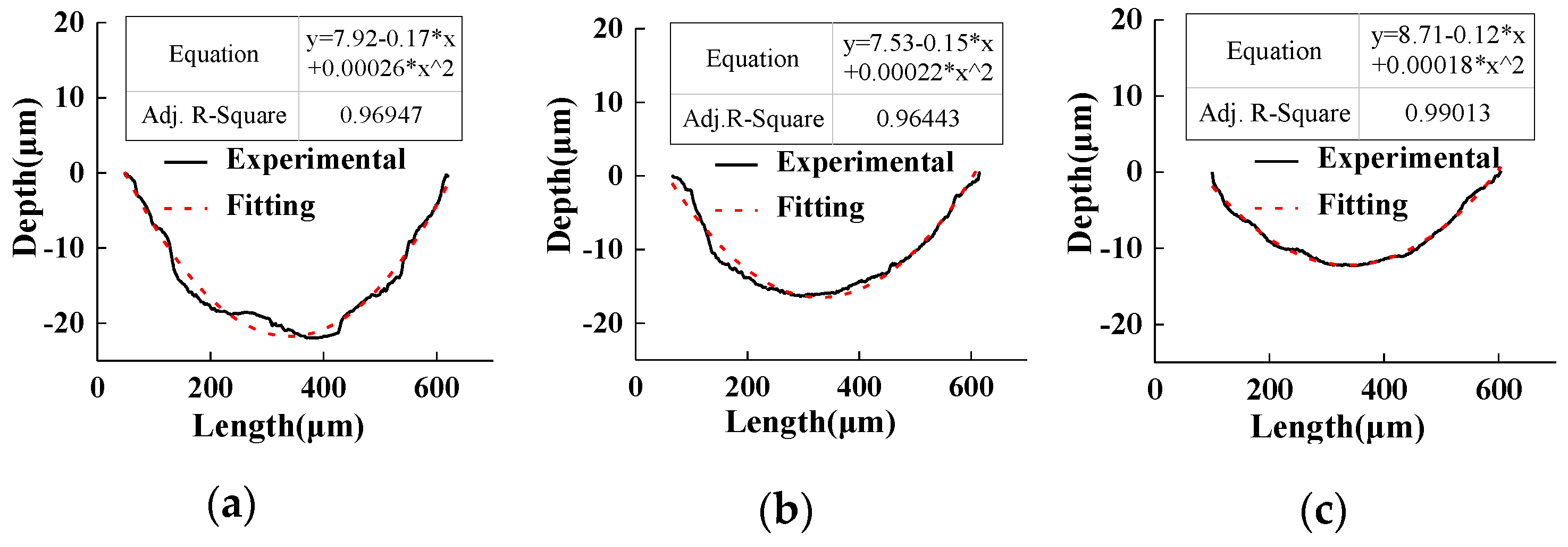
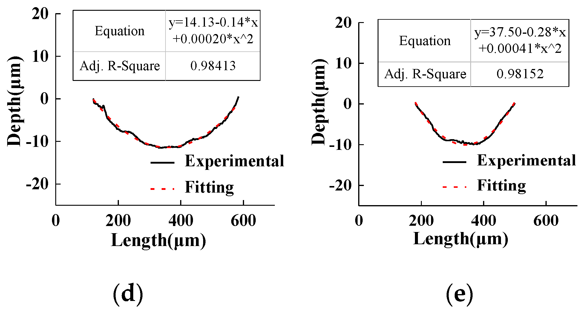
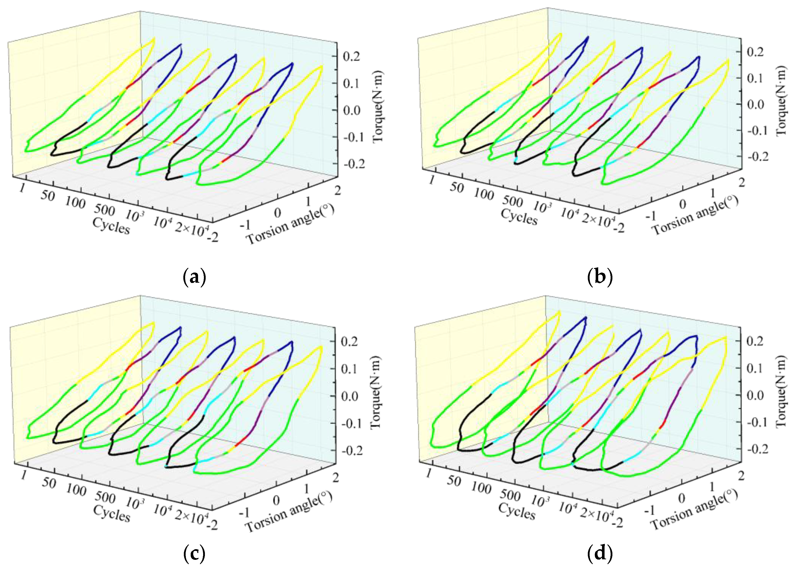
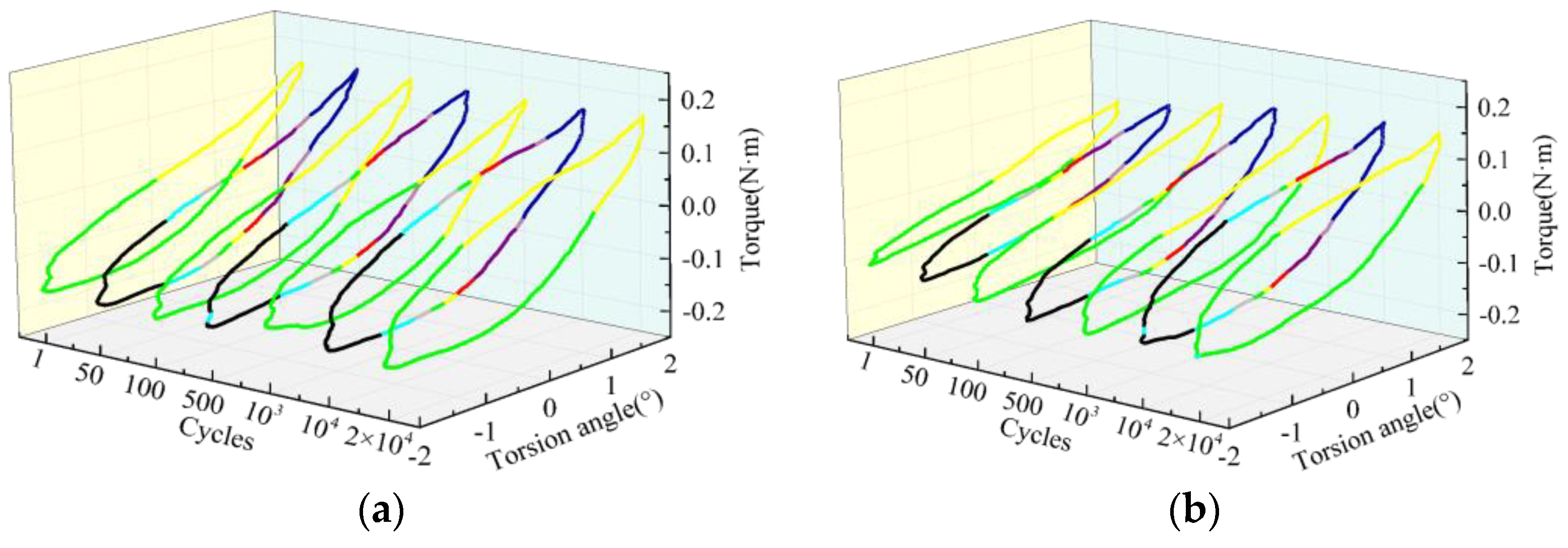
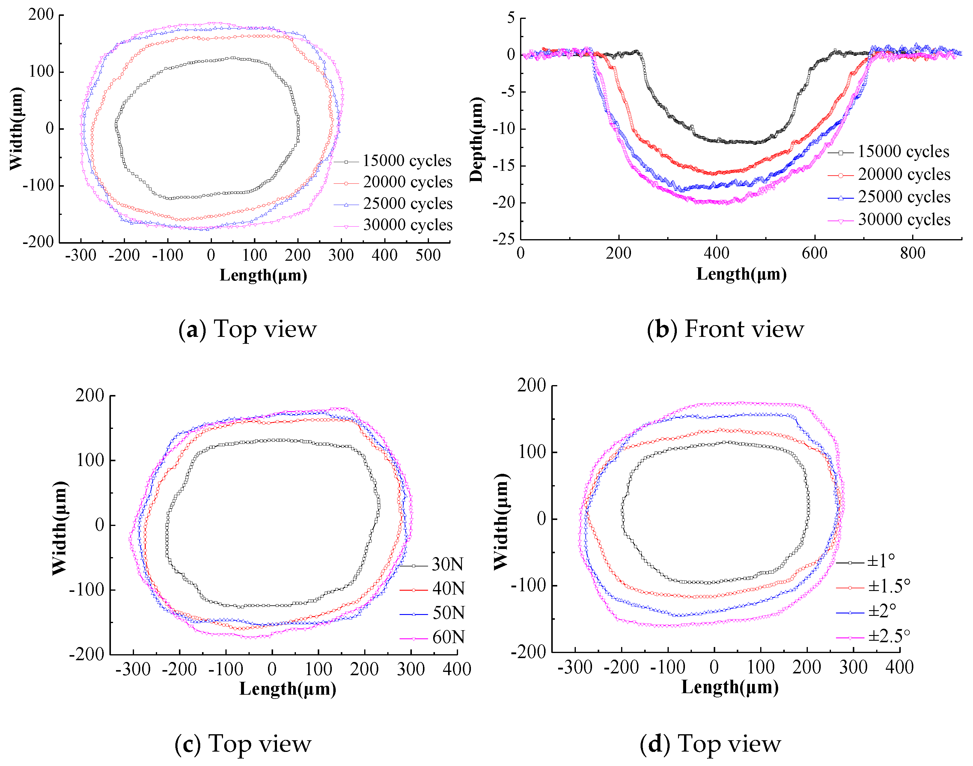
The objective of this study is to quantitatively demonstrate the wear rate and dissipation energy during tension–torsion cyclic loading of steel wires with fretting contact in distinct environmental media. Effects of environmental media (air, deionized water, solutions) and tension–torsion cyclic loading parameters (loading cycles, contact load, torsion angle and crossing angle) on hysteresis loops, dissipation energy, wear scar size and wear coefficient were presented, respectively.

2. Experimental

2.1. Test Specimens

The carbon structural steel wire with the diameter of 1 mm is chosen in this study. Chemical compositions (in wt%) of steel wires are: Fe 98.71%, C 0.87%, Mn 0.39%, Si 0.02% and Ni 0.01%. Steel wires have the elastic modulus of 203 GPa, yield strength of 1150 MPa and ultimate strength of 1680 MPa.

2.2. Environmental Media

Based on statistical data of PH values and chemical compositions of environmental solutions in typical coal mines in China [3,4], simulated solutions with different PH values (Table 1) were prepared using chemical materials of NaSO4, CaSO4, MgSO4, NaHCO3, NaOH, KCl, HCl, MgCl2 and NaCl.

2.3. Tension–Torsion Cyclic Loading Parameters

The tension–torsion cyclic loading test rig was employed to carry out tension–torsion cyclic loading tests of steel wires (see Figure 1 and Figure 2 in Reference [3]) in different environmental media. Before each test, loading wires were aligned with respect to the cyclic loaded wire to ensure consistent contact. During the test, the cyclic loaded wire was applied to the cyclic tension and torsion employing the electric cylinder and step motor, respectively. The constant contact load between contacting wires was applied using the counterweights. Contacting regions of steel wires were immersed in the plastic container with different environmental solutions to realize the corrosive environment. The cyclic tension and tangential force were recorded by the tension sensor and tangential force sensor, respectively. The cyclic torque and torsion angle of cyclic loaded wire are recorded employing the torque sensor and angular displacement sensor, respectively. The relative displacement between contacting wires is determined by scaling-down of the cyclic loaded wire deformation measured by the electric cylinder. Distinct crossing angles between steel wires can be realized by changing the inclination angle of loading wire fixture. Test parameters are as follows: fretting amplitude of ±60 μm, frequency of 5 Hz, tensile stress amplitude of 510 MPa and tensile stress ratio of 0.5. Environmental media and other test parameters can be found in Table 2. The white light interferometer is employed to investigate wear morphologies and depths of steel wires. Cross-section morphologies of cyclic loaded wires were investigated using X-ray computed tomography (CT). Fractures of cyclic loaded wires were observe employing the scanning electron microscope (SEM).

3. Results and Discussion

3.1. Effects of Environmental Media on Dissipation Energy Characteristics

3.1.1. Hysteresis Loops of Tangential Force versus Displacement Amplitude

It is clearly seen from Figure 1 that the displacement amplitude is composed of an elastic deformation part (DT) and relative slip (RS) between contacting wires [19,20]. Hysteresis loops of tangential force versus displacement amplitude (Ft-D) present shapes of parallelogram, ellipse and straight line, which indicates the gross slip, partial slip and adhesion state, respectively. All points at the fretting contact interface move relative to each other in the case of gross slip, while the partial slip state indicates the adhesion at the contact center of contacting wires and the micro-slip at the contact edge. In each environmental medium, the hysteresis loop presents the parallelogram at the initial stage of the tension–torsion cyclic loading test, which indicates the gross slip at contact surfaces of steel wires. As loading cycles increase, the hysteresis loop changes to the ellipse, which reveals a decrease in the relative slip range and an increase in the adhesion zone, i.e., partial slip state. As compared to the case of air medium, solutions and deionized water require fewer loading cycles for the transition of hysteresis loop from parallelogram to ellipse, which reveals easier removal of protection film at the wire surface and easier transition from gross slip to partial slip at the fretting contact surface in cases of solutions and deionized water. The maximum tangential force between steel wires decreases in the order: air, alkaline and neutral solutions, deionized water and acid solution (Figure 1e,f and Table 3). In cases of distinct media, the relative slip decreases in the order: acid, neutral and alkaline solutions, deionized water and air (Figure 1e and Table 3). In acid solution, wire surface wear is similar to “pickling and polishing”. Coupled roles of solution medium and SO42- lubricating film cause the good lubrication at the fretting contact surface, and thereby induce a smaller maximum tangential force and a larger relative slip [21,22]. In the case of deionized water, it presents the worse lubrication and no electrolyte ion effect as compared to the case of acid solution, which indicates a larger maximum tangential force and a smaller relative slip. In cases of neutral and alkaline solutions, interactions between Cl electrochemical corrosion and SO42− lubrication film cause the decreases in the maximum tangential force and relative slip [21,22]. The case of air medium presents the maximum tangential force and minimum relative slip attributed to the rough contact surface, discharge of accumulated debris and poor lubrication effect.
The dissipation energy attributed to cyclic tensile loading with fretting contact is characterized by the area inside Ft-D loop; the dissipation energy is mainly released in the form of friction heat due to material removal [23]. At loading cycles of 20,000, dissipation energies in cases of air, deionized water, acid, neutral and alkaline solutions are 1.0 × 10⁻³ J, 1.32 × 10⁻³ J, 1.46 × 10⁻³ J, 1.48 × 10⁻³ J and 1.62×10⁻³J, respectively. Therefore, in distinct environmental media, the dissipation energy decreases in the order: alkaline, neutral and acid solutions, deionized water and air. It is known that the dissipation energy is positively correlated with the product of maximum tangential force and relative slip. Larger dissipation energy indicates more difficult removal of surface material, which coincides with change trends of wear depth and wear coefficient as depicted in Section 3.1.3.

3.1.2. Hysteresis Loops of Torque versus Torsion Angle

Figure 2 shows evolutions of hysteresis loops of torque versus torsion angle during tension–torsion cyclic loading of steel wire with fretting contact in distinct environmental media. The hysteresis loop of torque versus torsion angle (T-θ) indicates friction dynamics characteristics of steel wire during cyclic torsional loading [24]. The linear hysteresis loop indicates the adhesion state at the fretting contact surface; the relative motion is mainly coordinated by the elastic deformation. The elliptical hysteresis loop reveals the partial slip state; relative motion is mainly coordinated by combined elastic and plastic deformations. In each environment medium, hysteresis loops of torque versus torsion angle present the ellipses, which indicates that the torsion angle lags behind the torque. The hysteresis phenomenon is more obvious at the stabilized stage as compared to the initial stage of the test. Increases of loading cycles cause increased degree of openness of hysteresis loop, which reveals that shear stress attributed to cyclic torsional loading with fretting contact causes more irreversible work absorbed by material internal friction and more severe wire surface damage.
At loading cycles 20,000, dissipation energies caused by cyclic torsional loading with fretting contact in cases of air, deionized water, acid, neutral and alkaline solutions are 9.26 × 10⁻³ J, 7.0 × 10⁻³ J, 9.97 × 10⁻³ J, 7.89 × 10⁻³ J and 7.98 × 10⁻³ J, respectively. Therefore, the dissipation energy decreases in the order: acid solution, air, alkaline and neutral solutions, and deionized water, which indicates most severe and slightest damages at fretting surfaces of cyclic loaded wires in cases of acid solution and deionized water, respectively.

3.1.3. Wear Coefficient

Figure 3 shows the irregularly elliptical front profile of wear scar of cyclic loaded wire in the case of acid solution. The long axis of ellipse shows an inclined angle γ with the wire axis attributed to combined roles of cyclic tension and torsion. Meanwhile, γ value coincides with the theoretical torsion angle amplitude, i.e., 4°. Table 4 shows sizes of wear scars of cyclic loaded wires in different environmental media. It is observed that in cases of different environmental media wear scar sizes decrease in the order: air, acid, alkaline and neutral solutions, and deionized water.
Based on wear depth profiles (Figure 3 and Figure 4 and Table 4) and polynomial fitting, theoretical equations of wear depth profiles are established as shown in Figure 5. According to theoretical equations of wear depth profiles, the three-dimensional geometric model of wear scar is reconstructed using Pro/Engineer 5.0, PTC, Massachusetts, USA (see Figure 5 in reference [25]). The wear volume between surfaces of P and Q can be calculated automatically by Pro/Engineer 5.0. Substitutions of wear volume, relative slip amplitude, loading cycles and contact load into formula (1) derives the cyclic wear coefficient, i.e., the wear volume per unit local relative slip and per unit contact load [25,26]:
k c o f = V S x F n = V 2 Δ x N F n
where Sx is the total stroke, Fn denotes the contact load, and Δx represents the relative slip. In the present study, Δx is equal to relative displacement amplitude for simplicity.
Coefficients of cyclic wear can be calculated using Equation (1). In cases of distinct environmental media, the wear coefficient decreases in the order: air, acid, neutral and alkaline solutions, and deionized water, i.e., Kcof = 8.25 × 10⁻³ μm2/N, 4.58 × 10⁻³ μm2/N, 2.85 × 10⁻³ μm2/N, 2.4 × 10⁻³ μm2/N and 1.44 × 10⁻³ μm2/N, respectively. In cases of solutions, wear scars of cyclic loaded wires present the smaller wear depth (Table 4) and wear coefficient, as compared to the air medium, which reveals the negative interaction between wear and electrochemical corrosion. In the case of deionized water, no electrochemical corrosion and better lubrication effect cause a smaller wear coefficient as compared to solutions. In the acid solution, H+ dissolves the debris and exfoliation products, and thus accelerates fretting wear. Meanwhile, the lubrication and polishing effect may reduce the wear between contacting wires.
In the neutral solution, the strong electrochemical effect due to great Cl concentration counteracts the lubrication effect of electrolyte solution [20,21,22,27]. In the alkaline electrolyte solution, the contact surface exhibits corrosion resistant passivation film due to OH concentration, decreased lubricating effect due to great Cl concentration, and weakened electrochemical corrosion of chloride attributed to decreased Mg2+, Ca2+, Na+ contents [20]. Therefore, the acid solution presents the largest wear depth and wear coefficient as compared to cases of neutral and alkaline solutions, while neutral and alkaline solutions exhibit essentially the same wear coefficient attributed to complex interactions of ions.

3.2. Effects of Fretting and Torsional Parameters on Dissipation Energy Characteristics

3.2.1. Hysteresis Loops of Tangential Force versus Displacement Amplitude

(1)
Effects of loading cycles
Figure 5a shows that increases of loading cycles cause the transition of hysteresis loop from parallelogram to ellipse and finally stabilized ellipse. That indicates the contact state between steel wires change from a gross slip to a partial slip, which induces a decrease in relative slip (Figure 5b) and an increase in adhesion zone. Figure 5b shows that the dissipation energy (area of hysteresis loop) created by cyclic tensile loading with fretting contact presents an increase at first, then a decrease and the final stabilization. At the initial stage, the protective film is removed from the fretting contact surface of cyclic loaded wire attributed to the fretting wear and corrosion, which causes the friction between steel matrix of wires and thus induces a rapid increase in the tangential force between contact surfaces. Therefore, the dissipation energy increases at first. Afterwards, the regulation and load-bearing of wear debris and corrosion products as the third body cause the decreased tangential force and dissipation energy. At the stabilized stage, dynamic equilibriums between formations and dissolutions of wear debris and corrosion products cause the stabilized tangential force. The relative slip between steel wires decreases at first and then stabilizes with increasing loading cycles. Therefore, combined roles of tangential force and relative slip induces the change trend of increase-decrease-stabilization of dissipation energy.
(2)
Effect of contact load
Figure 6a shows parallelogram Ft-D loops at contact load of 30 N, which indicates the gross slip state. Figure 6b-d show that the hysteresis loop changes from the parallelogram to ellipse with increasing loading cycles at contact loads of 40 N, 50 N and 60 N, which indicates that the fretting contact state varies from the gross slip to the partial slip, i.e., a decrease in the relative slip and an increase in the adhesion zone. An increase of contact load induces decreased loading cycles required for the hysteresis loop transition from parallelogram to ellipse, which indicates more difficult relative slip due to larger elastic deformation between contacting surfaces. An increase of contact load from 30 N to 60 N causes an increase in the maximum tangential force from 14.4 N to 20.0 N and a decrease in the relative slip from 78.4 μm to 23.4 μm at loading cycles 20,000 (Table 5). In cases of contact loads of 30 N, 40 N, 50 N and 60 N, dissipation energies are 1.728 × 10⁻³ J, 1.456 × 10⁻³ J, 0.732 × 10⁻³ J and 0.743 × 10⁻³ J, respectively. Therefore, the dissipation energy decreases firstly and then changes in a subtle manner with increasing contact load due to cyclic tensile loading with fretting contact. As the contact load increases from 50 N to 60 N, the unobvious change of dissipation energy is mainly attributed to an increase in the maximum tangential force and a decrease in the relative slip.
(3)
Effect of torsion angle
Figure 7 shows that the hysteresis loop changes from parallelogram to ellipse in the case of each torsion angle, which indicates the fretting contact state changing from gross slip to partial slip. An increase of torsion angle induces increases in loading cycles required for the transition of hysteresis loop from parallelogram to ellipse, which indicates more difficult change of fretting contact state from gross slip to partial slip. Table 5 shows that the maximum tangential force and relative slip increases with increasing torsion angle at loading cycles 20,000. In cases of torsion angles of ±1°, ±1.5°, ±2° and ±2.5°, at loading cycles 20,000, dissipation energies are 1.0574 × 10⁻³ J, 1.4881 × 10⁻³ J, 1.5582 × 10⁻³ J and 1.599 × 10⁻³ J, respectively. Therefore, an increase of torsion angle causes an overall increase in the dissipation energy.
(4)
Effect of crossing angle
It is clearly seen from Figure 5 in reference [3] that at crossing angles of 90° and 70° between steel wires, increases of loading cycles induce the change of Ft-D loop from parallelogram to ellipse, which indicates the fretting contact state changing from gross slip to partial slip; the maximum tangential force increases gradually, and the relative slip between steel wires presents the overall decrease trend. At crossing angles of 45° and 26°, increases of loading cycles cause the parallelogram-ellipse change trend of hysteresis loop. Therefore, the maximum tangential force increases at first and then decreases, while the relative slip decreases at first and then increases. Partial slip states at crossing angles of 45° and 26° are attributed to the destruction of longitudinal fiber grain structure after the failure of surface protection film of steel wire [28]. Figure 5 in reference [3] and Table 6 show that at loading cycles 20,000, an increase of crossing angle causes overall decreases in maximum tangential force, relative slip and dissipation energy, which indicates accelerated cyclic loaded wire surface damage [3,19].

3.2.2. Hysteresis Loops of Torque versus Torsion Angle

(1)
Effect of loading cycles
Figure 8a shows elliptical hysteresis loops at different loading cycles, which indicates that the fretting contact surface is mainly regulated by coupled elastic and plastic deformations [29]. Increases of loading cycles induce increases in the openness of hysteresis loop, relative slip range and plastic deformation. Figure 8b shows the increase in the area of hysteresis loop with increasing loading cycles, which reveals increases in the dissipation energy due to cyclic torsional loading with fretting contact and the fretting contact surface damage.
(2)
Effect of contact load
Figure 9 shows elliptical hysteresis loops of torque versus torsion angle in cases of different contact loads. At each contact load, increases of loading cycles cause increased openness of hysteresis loop. At the same loading cycles, the openness of hysteresis loop increases with increasing contact load. At loading cycles 20,000, dissipation energies due to cyclic torsional loading with fretting contact in cases of contact loads of 30 N, 40 N, 50 N and 60 N are 9.14 × 10⁻³ J, 9.97 × 10⁻³ J, 11.9 × 10⁻³ J and 16.2 × 10⁻³ J, respectively. Therefore, the dissipation energy increases with increasing contact load and thereby the fretting contact surface damage of cyclic loaded wire increases.
(3)
Effect of torsion angle
Figure 10a–d shows elliptical hysteresis loops of torque versus torsion angle in cases of different torsion angles. At each torsion angle, the openness of hysteresis loop increases with increasing loading cycles, which indicates that the cyclic torsional loading with fretting contact always runs at the partial slip state. At the same loading cycles, the openness of hysteresis loop increases with increasing torsion angle, which reveals increases in the relative slip and fretting contact surface damage. The nonlinear increase of torque with increasing torsion angle may be attributed to the elastic–plastic torsional deformation according to Material Mechanics and complex elastic–plastic fretting contact role [30]. At loading cycles of 20,000, dissipation energies due to cyclic torsional loading with fretting contact are 4.11 × 10⁻³ J, 6.73 × 10⁻³ J, 9.97 × 10⁻³ J and 17.0 × 10⁻³ J, respectively. Therefore, the dissipation energy and fretting contact surface damage of cyclic loaded wire both increase with increasing torsion angle.
(4)
Effect of crossing angle
Figure 11a–d shows elliptical hysteresis loops of torque versus torsion angle during the test in each crossing angle case. In cases of crossing angles of 90°, 70° and 45°, increases of loading cycles cause the increase in the openness of hysteresis loop. In the case of crossing angle of 26°, the large openness of hysteresis loop does not vary obviously, which indicates the large relative slip during the whole test. At loading cycles of 20,000, dissipation energies in cases of crossing angles of 90°, 70°, 45° and 26° are 9.97 × 10⁻³ J, 9.36 × 10⁻³ J, 6.95 × 10⁻³ J and 6.37 × 10⁻³ J, respectively. Therefore, an increase of crossing angle induces increases in the dissipation energy and thus the fretting contact surface damage of cyclic loaded wire.

3.2.3. Wear Scar Size

Figure 12 shows that wear scars of cyclic loaded wires all exhibit irregular ellipses. Coupled roles of tension and torsion induce certain inclinations between the cyclic loaded wire axis and long axis of elliptical scar. Different tension–torsion cyclic loading parameters (loading cycles, contact load, torsion angle and crossing angle) cause distinct inclinations attributed to distinct relative slips and torsional slips between contacting surfaces, which coincide well with results in Section 3.2.1 and Section 3.2.2. Table 7 and Table 8 show that as loading cycles, contact load, torsion angle and crossing angle increase, the maximum wear depth varies in ranges of 11.9–20.1 μm, 10.4–19.5 μm, 9.2–19.9 μm and 7.2–16.0 μm, respectively. Therefore, increases of tension–torsion cyclic loading parameters all cause the overall increases in wear scar dimensions, which coincides well with conclusions in Section 3.2.1 and Section 3.2.2.

3.2.4. Wear Coefficient

Table 9 shows that as loading cycles increase, the wear coefficient increases rapidly at first, then increases slowly and finally stabilizes. At the initial stage of test, the protection film is removed from the contact surface of cyclic loaded wire attributed to roles of fretting wear and corrosion, which causes the fretting wear between steel matrixes and thereby accelerates the wear of cyclic loaded wire. Then the third body (debris and corrosion products) participates in the regulation and load-bearing, which causes a slow increase in the wear coefficient. Finally, the stable wear coefficient is attributed to dynamic balance between generation and dissolution of debris and corrosion products.
The coefficient of cyclic wear increases at first and then decreases with increasing contact load. As depicted in Section 3.2.3, the wear volume increases with increasing contact load and thus causes an increase in the wear coefficient. However, a further increase of contact load accelerates the adhesion at the fretting contact surface, which indicates that the acid solution is difficult to enter the contact surface, and relative slip between contact surfaces is smaller. Therefore, both decreases in fretting corrosion and relative slip reduce the wear coefficient.
An increase of torsion angle induces an overall increase in the wear coefficient. The tangential force and torque both increase with increasing torsion angle, which induces more severe plastic deformation and more irreversible work absorbed by the internal friction attributed to shear stress. Therefore, the acid solution enters the fretting contact surface more easily and thereby causes an increase in the wear coefficient.
The coefficient of cyclic wear increases with increasing crossing angle, which coincides with results in [31]. An increase of crossing angle induces easier failure of grain texture due to longitudinal fibrous grain [32], and increased maximum torque indicating larger shear failure.

4. Conclusions

The dissipation energy due to cyclic tensile loading with fretting contact decreases in the order: electrolyte solutions, deionized water and air, while the dissipation energy due to cyclic torsional loading with fretting contact exhibits the maximum and minimum values in cases of acid solution and deionized water, respectively. In the case of cyclic tensile loading with fretting contact, the dissipation energy increases with increasing torsion angle and PH value of electrolyte solution and with decreasing contact load and crossing angle. In the case of cyclic torsional loading with fretting contact, the dissipation energy increases with increasing contact load, crossing angle, torsion angle and PH value of electrolyte solution. The coefficient of cyclic wear decreases in the order: air, acid, solution, and alkaline solutions, and deionized water, and increases with increasing contact load, torsion angle and crossing angle.

Author Contributions

D.W. proposed the idea, conception and design of the manuscript, participated in the analysis and interpretation of the data, and revised the manuscript critically for important intellectual content. X.W. carried out related tests, participated in the analysis of the data and drafting the text. G.X. and H.Z. participated in the data processing, format typesetting and English language editing. All authors have read and agreed to the published version of the manuscript.

Funding

The research was supported by National Natural Science Foundation of China (Grant No. 51875565) and Chinese Postdoctoral Science Foundation (2019M652001, 2020T130695). The authors also wish to thank TAPP and PAPD.

Conflicts of Interest

All authors have approved the final version of the manuscript. This manuscript has not been submitted to, nor is under review at, another journal or other publishing venue. All authors have no affiliations with organizations with direct or indirect financial interest in the subject matter discussed in the manuscript. The Author has the following nonexclusive rights: (1) to use the manuscript in the Author’s teaching activities; (2) to publish the manuscript, or permit its publication, as part of any book the Author may write; (3) to include the manuscript in the Author’s own personal or departmental (but not institutional) database or on-line site; and (4) to license reprints of the manuscript to third persons for educational photocopying. The Author also agrees to properly credit Applied Sciences as the original place of publication.

References

  1. Wang, D.G.; Li, X.W.; Wang, X.R.; Shi, G.Y.; Mao, X.B.; Wang, D.A. Effects of hoisting parameters on dynamic contact characteristics between the rope and friction lining in a deep coal mine. Tribol. Int. 2016, 96, 31–42. [Google Scholar] [CrossRef]
  2. Wang, X.R.; Wang, D.G.; Zhang, D.K.; Ge, S.R.; Araújo, J.A. Effect of torsion angle on tension-torsion multiaxial fretting fatigue behaviors of steel wires. Int. J. Fatigue 2018, 106, 159–164. [Google Scholar] [CrossRef]
  3. Wang, D.G.; Song, D.Z.; Wang, X.R.; Zhang, D.K.; Zhang, C.L.; Wang, D.A.; Araújo, J.A. Tribo-fatigue behaviors of steel wires under coupled tension-torsion in different environmental media. Wear 2019, 420–421, 38–53. [Google Scholar] [CrossRef]
  4. Wang, D.G.; Zhang, D.K.; Zhao, W.J.; Ge, S.R. Quantitative analyses of fretting fatigue damages of mine rope wires in different corrosive media. Mater. Sci. Eng. A 2014, 596, 80–88. [Google Scholar] [CrossRef]
  5. Llavori, I.; Zabala, A.; Otano, N.; Tato, W.; Gómez, X. Development of a modular fretting wear and fretting fatigue tribometer for thin steel wires: Design concept and preliminary analysis of the effect of crossing angle on tangential force. Metals 2019, 9, 674. [Google Scholar] [CrossRef] [Green Version]
  6. Takeuchi, M.; Waterhouse, R.B. An investigation into the fretting-corrosion-fatigue of high strength steel wire. Key Eng. Mater. 1991, 20–28, 1959–1966. [Google Scholar] [CrossRef]
  7. Zhang, D.K.; Geng, H.; Zhang, Z.F.; Wang, D.G.; Wang, S.Q.; Ge, S.R. Investigation on the fretting fatigue behaviors of steel wires under different strain ratios. Wear 2013, 303, 334–342. [Google Scholar] [CrossRef]
  8. Périera, V.; Dienga, L.; Gaillet, L.; Tessier, C.; Fouvry, S. Fretting-fatigue behavior of bridge engineering cables in a solution of sodium chloride. Wear 2009, 267, 308–314. [Google Scholar] [CrossRef]
  9. Périera, V.; Dienga, L.; Gaillet, L.; Fouvry, S. Influence of an aqueous environment on the fretting behavior of steel wires used in civil engineering cables. Wear 2011, 271, 1585–1593. [Google Scholar] [CrossRef]
  10. Cruzado, A.; Leen, S.B.; Urchegui, M.A.; Gómez, X. Finite element simulation of fretting wear and fatigue in thin steel wires. Int. J. Fatigue 2013, 55, 7–21. [Google Scholar] [CrossRef]
  11. Winkler, J.; Georgakis, C.T.; Fischer, G. Fretting fatigue behavior of high-strength steel monostrands under bending load. Int. J. Fatigue 2015, 70, 13–23. [Google Scholar] [CrossRef]
  12. Wokem, C.; Joseph, T.G.; Curley, M. Fatigue prediction for hoist cables over sheaves in large mining shovel application. Fatigue Fract. Eng. M 2018, 41, 1838–1852. [Google Scholar] [CrossRef]
  13. Liu, H.T.; Zhang, D.K.; Cao, S.F.; Shen, Y.; Hou, X.H.; Xu, L.M. Fretting corrosion wear behaviors of steel wires in hoisting ropes in alkaline condition. Appl. Mech. Mater. 2011, 99–100, 1014–1017. [Google Scholar] [CrossRef]
  14. Nakamura, S.I.; Suzumura, K.; Tarui, T. Mechanical properties and remaining strength of corroded bridge wires. Struct. Eng. Int. 2004, 14, 50–54. [Google Scholar] [CrossRef]
  15. Smallwood, R.; Waterhouse, R.B. Residual Stress Patterns in Cold Drawn Steel Wires and Their Effect on Fretting-Corrosion-Fatigue Behaviour in Seawater. In Applied Stress Analysis; Hyde, T.H., Ollerton, E., Eds.; Springer: Dordrecht, The Netherlands, 1990. [Google Scholar] [CrossRef]
  16. Wang, D.G.; Wahab, M.A.; Wang, L.L.; Li, X.W.; Zhu, Z.C.; Zhang, D.K.; Ge, S.R.; Mao, X.B. Finite element analysis of fretting fatigue of fretted wires. In Proceedings of the 4th International Conference on Fracture Fatigue and Wear, Ghent, Belgium, 27–28 August 2015; pp. 135–142. Available online: http://hdl.handle.net/1854/LU-6879721 (accessed on 14 July 2015).
  17. Urchegui, M.A.; Hartelt, M.; Wäsche, R.; Gómez, X. Analysis of different strategies to reduce fretting wear in thin steel roping wires. Tribotest 2008, 14, 43–57. [Google Scholar] [CrossRef]
  18. Bonneric, M.; Aubin, V.; Durville, D. Fatigue damage mechanisms in steel cable under bending loading. Eng. Fail. Anal. 2019, 106, 104184. [Google Scholar] [CrossRef]
  19. Wang, D.G.; Zhang, D.K.; Ge, S.R. Effect of displacement amplitude on fretting fatigue behavior of hoisting rope wires in low cycle fatigue. Tribol. Int. 2012, 52, 178–189. [Google Scholar] [CrossRef]
  20. Wang, D.G.; Zhang, D.K.; Ge, S.R. Fretting–fatigue behavior of steel wires in low cycle fatigue. Mater. Des. 2011, 32, 4986–4993. [Google Scholar] [CrossRef]
  21. Mi, X.; Cai, Z.B.; Xiong, X.H.; Qian, H.; Tang, L.C.; Xie, Y.C.; Peng, J.F.; Zhu, M.H. Investigation on fretting wear behavior of 690 alloy in water under various temperatures. Tribol. Int. 2016, 100, 400–409. [Google Scholar] [CrossRef] [Green Version]
  22. Husain, E.; Narayanan, T.N.; Taha-Tijerina, J.J.; Vinod, S.; Vajtai, R.; Ajayan, P.M. Marine corrosion protective coatings of hexagonal boron nitride thin films on stainless steel. ACS Appl. Mater. Interfaces 2013, 5, 4129–4135. [Google Scholar] [CrossRef]
  23. Wang, X.R.; Wang, D.G.; Li, X.W.; Zhang, D.K.; Ge, S.R.; Araujo, J.A. Comparative analyses of torsional fretting, longitudinal fretting and combined longitudinal and torsional fretting behaviors of steel wires. Eng. Fail. Anal. 2018, 85, 116–125. [Google Scholar] [CrossRef]
  24. Wang, X.R. Study on Multiaxial Fretting Corrosion Fatigue Damage Mechanism of Steel Wires; China University of Mining and Technology: Xuzhou, China, 2018. [Google Scholar]
  25. Wang, D.G.; Zhang, J.; Li, X.W.; Zhang, D.K. Dynamic wear evolution of steel wires during multi-axial fretting-fatigue. In Proceedings of the 1st International Conference on Frontiers of Materials Synthesis and Processing (FMSP 2017), Changsha, China, 28–29 October 2017; Volume 274. [Google Scholar] [CrossRef]
  26. Wang, D.G.; Zhang, D.K.; Wang, S.Q.; Ge, S.R. Finite element analysis of hoisting rope and fretting wear evolution and fatigue life estimation of steel wires. Eng. Fail. Anal. 2013, 27, 173–193. [Google Scholar] [CrossRef]
  27. Solomon, M.M.; Gerengi, H.; Umoren, S.A. Carboxymethyl Cellulose/silver nanoparticles composite: Synthesis, characterization and application as a benign corrosion inhibitor for St37 steel in 15% H2SO4 medium. ACS Appl. Mater. Interfaces 2017, 9, 6376–6389. [Google Scholar] [CrossRef] [PubMed]
  28. Fang, F.; Zhou, L.C.; Hu, X.J.; Zhou, X.F.; Tu, Y.Y.; Xie, Z.H.; Jiang, J.Q. Microstructure and mechanical properties of cold-drawn pearlitic wires affect by inherited texture. Mater. Des. 2015, 79, 60–67. [Google Scholar] [CrossRef]
  29. Zheng, J.F. Studies on Fretting Wear Behaviors of Axle Steels under Varied Modes; South Jiaotong University: Chengdu, China, 2006. [Google Scholar]
  30. Wang, S.B.; Niu, C.C. Torsional tribological behavior and torsional friction model of polytetrafluoroethylene against 1045 steel. PLoS ONE 2016, 11, e0147598. [Google Scholar] [CrossRef] [Green Version]
  31. Cruzado, A.; Hartelt, M.; Wasche, R.; Urchegui, M.A.; Gómez, X. Fretting wear of thin steel wires. Part 2: Influence of crossing angle. Wear 2011, 273, 60–69. [Google Scholar] [CrossRef]
  32. Safarov, I.M.; Korznikov, A.V.; Galeev, R.M.; Sergeev, S.N.; Gladkovskii, S.V.; Borodin, E.M.; Pyshmintsev, I.Y. Strength and impact toughness of low-carbon steel with fibrous ultrafine-grained structure. Phys. Met. Met. 2014, 115, 295–302. [Google Scholar] [CrossRef]
Figure 1. Ft-D loops during tension–torsion cyclic loading of steel wires with fretting contact in different environmental media. (a) air; (b) acid solution; (c) neutral solution; (d) alkaline solution; (e) deionized water; (f) comparison of hysteresis loops at loading cycles of 20,000.
Applsci 10 06610 g001aApplsci 10 06610 g001b
Figure 2. Hysteresis loops of torque versus torsion angle during tension–torsion cyclic loading of steel wires with fretting contact in different environmental media. (a) Air. (b) Acid solution. (c) Neutral solution. (d) Alkaline solution. (e) Deionized water.
Applsci 10 06610 g002
Figure 3. Three-dimensional white light interference surface morphology of wear scar of cyclic loaded wire in the case of acid solution.
Applsci 10 06610 g003
Figure 4. Fitting of wear depth profiles of cyclic loaded wires in cases of distinct environmental media. (a) Air. (b) Acid solution. (c) Neutral solution. (d) Alkaline solution. (e) Deionized water.
Applsci 10 06610 g004aApplsci 10 06610 g004b
Figure 5. Effects of cycles of loading on hysteresis loops of tangential force versus displacement amplitude and the relative slip. (a) Hysteresis loops. (b) Relative slip and hysteresis loop area.
Applsci 10 06610 g005
Figure 6. Ft-D loops during tension–torsion cyclic loading of steel wires with fretting contact in cases of distinct contact loads. (a) Fn = 30 N. (b) Fn = 40 N. (c) Fn = 50 N. (d) Fn = 60 N.
Applsci 10 06610 g006
Figure 7. Evolutions of hysteresis loops of tangential force versus displacement amplitude during tension–torsion cyclic loading of steel wires with fretting contact at different torsion angles. (a) θ = ±1°. (b) θ = ±1.5°. (c) θ = ±2°. (d) θ = ±2.5°.
Applsci 10 06610 g007
Figure 8. Evolutions and dissipation energy of torque versus torsion angle. (a) Evolution of the hysteresis loop. (b) Dissipation energy at loading cycles 20,000.
Applsci 10 06610 g008
Figure 9. Evolutions of torque versus torsion angle during tension–torsion cyclic loading at different contact loads. (a) Fn = 30 N. (b) Fn = 40 N. (c) Fn = 50 N. (d) Fn = 60 N.
Applsci 10 06610 g009
Figure 10. Evolutions and dissipation energy of torque versus torsion angle during tension–torsion cyclic loading at different torsion angles. (a) θ = ±1°. (b) θ = ±1.5°. (c) θ = ±2°. (d) θ = ±2.5°.
Applsci 10 06610 g010
Figure 11. Evolutions and dissipation energy of torque versus torsion angle during tension–torsion cyclic loading at different crossing angles. (a) β = 90°. (b) β = 70°. (c) β = 45°. (d) β = 26°.
Applsci 10 06610 g011aApplsci 10 06610 g011b
Figure 12. Top and front views of wear scars of cyclic loaded wires at different tension–torsion cyclic loading parameters.(a,b) Effects of loading cycles; (c) and Figure 7c in reference [3] effect of contact load; (d) and Figure 7d in reference [3] effect of torsion angle; (e) and Figure 7b in reference [3] effect of crossing angle.
Applsci 10 06610 g012aApplsci 10 06610 g012b
Table 1. Chemical compositions of solutions.
PH Ion Content (mg/L)
H+Na+K+Mg2+Ca2+ClOH HCO 3 SO 4 2
3.51.2892.4211.73364.74676.5528.36/18.923283.81
7.5/141.1611.7349.3380.5689.33/18.92551.38
9.5/35.6311.7336.4554.4389.333.3318.92232.95
Table 2. Environmental media and tension–torsion cyclic loading test parameters.
Environmental MediaCrossing Angle,
β (°)
Contact Load,
Fn (N)
Torsion Angle,
θ (°)
Loading Cycles, N (×104)
Air; deionized water; acid, neutral and alkaline solutions9040±22
Acid solution9040±21.5, 2, 2.5, 3
30, 40, 50, 60±22
9040±1, ±1.5, ±2, ±2.52
90, 70, 45, 2640±22
Table 3. The maximum tangential force and relative displacement at loading cycles 20,000 in different environmental media.
Environmental MediaAirAcid SolutionNeutral SolutionAlkaline SolutionDeionized Water
Maximum tangential force (N)21.316.218.019.117.3
Relative displacement (μm)33.658.554.351.249.1
Table 4. Sizes of wear scars of cyclic loaded wires in different environmental media.
Environmental MediaAirAcid SolutionNeutral SolutionAlkaline SolutionDeionized Water
Max. length, L (μm)623553515493359
Max. width, w (μm)385327309289225
Max. depth, h (μm)21.9316.0312.2211.249.87
Scar area, s (μm2)187,963145,460127,095109,31966,375
Table 5. Tangential forces and relative slips between steel wires during tension–torsion cyclic loading at loading cycles 20,000 with different tension–torsion cyclic loading parameters.
Contact Load, Fn, (N)Torsion Angle, θ (°)Crossing Angle, β (°)
30405060±1±1.5±2±2.590704526
Max. tangential force (N)14.416.218.820.013.815.216.216.616.219.019.420.1
Relative slip (μm)78.458.525.023.443.358.058.560.858.548.659.161.2
Table 6. Tangential forces and relative slips between steel wires during tension–torsion fretting fatigue and dissipation energies of tangential force versus displacement amplitude at fatigue cycles 20,000 at different crossing angles.
Crossing Angle, β (°)90704526
Maximum tangential force (N)16.219.019.420.1
Relative slip (μm)58.548.659.161.2
Dissipation energy (×10-3 J)1.461.521.832.01
Table 7. Dimensions of wear scars of cyclic loaded wires at different loading cycles and contact loads.
Loading Cycles, N (104)Contact Load, Fn (N)
1.522.5330405060
Max. length, L (μm)395553584601458553580588
Max. width, w (μm)245327353358250327333347
Max. wear depth, h (μm)11.8916.0318.1720.0610.3816.0318.2719.54
Scar area, s (μm2)82,074145,460170,246183,28497,692145,460159,324166,888
Table 8. Dimensions of wear scars of cyclic loaded wires at different torsion angles and crossing angles.
Torsion Angle, θ (°)Crossing Angle, β (°)
±1±1.5±2±2.590704526
Max. length, L (μm)401549553567553659687778
Max. width, w (μm)210269327334327303298229
Max. wear depth, h (μm)9.2111.6516.0319.9516.0310.138.497.21
Scar area, s (μm2)70,073110,783145,460157,927145,460154,131161,380120,787
Table 9. Coefficients of cyclic wear at different fretting and torsional parameters.
Loading Cycles (×104)Contact Load (N)Torsion Angle (°)Crossing Angle (°)
1.522.5330405060±1±1.5±2±2.526456090
Wear coefficient (×10-3 μm2/N)2.84.64.74.72.64.64.74.41.52.84.66.52.02.22.84.6

