1. Introduction
Since 2012, China’s external dependence on crude oil has reached 71.2%, which is seriously affecting our country’s energy security and is constraining socio-economic development [
1,
2]. In order to ensure an increase in the reserves and production of crude oil in our country, rotary steerable drilling technology could effectively enhance drilling speed, reduce drilling costs, and decrease production accidents [
3,
4]. Following nearly two decades of research, it is imperative for the domestic development of rotary steerable tools to enter an accelerated phase. During the drilling process, the rotary steerable system could ensure that the wellbore trajectory is drilled at the set angle, and the key technology to achieve this goal is to achieve the stable control of the stabilized platform at any given angle [
5,
6,
7].
The stabilized platform of the full rotary steerable drilling system is a complex system that integrates mechanics, electronics, and hydraulics. Even small disturbance torques could lead to oscillations or even instability. Therefore, many scholars have conducted continuous research and exploration to achieve a stable control of the stabilized platform. Reference [
8] proposed a variable structure control method to address the issue of the stabilized platform instability that is caused by external disturbances. Reference [
9] designed a cascaded controller for the stabilized platform, conducted extensive experimental research on control algorithms and parameters for an extended period, and achieved a short-term stability in the stabilized platform system under certain conditions. Reference [
10] conducted numerical simulations based on the nonlinear dynamics model of the stable platform, and the study also revealed the general impact of the platform structure and disturbance parameters on platform motion. Reference [
11] developed a feedback linearization controller for the stabilized platform to resolve the instability problem in angle control that arises from the eccentricity of platform mass distribution and structure. In order to address the instability issue in stable platform control that is caused by large-range variations in the drilling fluid flow rate, reference [
12] proposed a turbine motor electromagnetic torque feedforward control method. Reference [
13] presented a three-loop compound toolface control based on the model with an active disturbance rejection control algorithm to ensure the stabilized platform traces the directional command accurately and rapidly. Reference [
14] established a state observer to estimate the trajectory orientation based on the measurement of the bottom hole assembly to reduce control errors in practice. Reference [
15] proposed an observer-based, adaptive neural network, and the researchers also used the dynamic surface control strategy to improve the anti-interference ability of the stabilized platform control system. Reference [
16] established a mathematical and friction model for the stabilized platform in a rotary steerable drilling system, and the researchers also introduced an improved deep deterministic policy gradient attitude control method with the stabilized platform attitude control system. Reference [
17] devised a disturbance–observer-based deep deterministic policy gradient control algorithm to address the friction nonlinearity problem that exists in the rotary steering drilling stabilized platform.
Even if the above studies provided deep insights into the modeling and control of the stabilized platform for a rotary steerable drilling system, most of them could only achieve stability in the rotary steerable drilling tool under specific conditions, and they also observed poor adaptability to drilling fluid flow rates at large displacements. Due to the harsh working environment underground, the rotary steerable tool is susceptible to factors such as vibration, high temperature, and high pressure during the drilling process, which could easily lead to changes in the structural and electrical parameters of the stabilized platform system [
18,
19]. Consider these influences as disturbances and eliminate their impact on the control of the stabilized platform by improving the robustness of the control method. How to improve the robustness of the stabilized platform control system under complex drilling environments motivates the work in this paper.
Among the many nonlinear control methods, the backstepping control method is the easiest to combine with adaptive techniques. As such, the adaptive backstepping control approach has good adaptability and robustness for systems with uncertain parameters [
20,
21,
22]. In this paper, we utilized the adaptive backstepping control method and constructed a suitable Lyapunov function to ensure global asymptotic stability, and this is expected to improve the robustness of the stabilized platform control system. Specifically, the main contributions of this paper are highlighted as follows.
- (1)
Based on the nonlinear mathematical model of the stabilized platform system, the adaptive backstepping control was designed. Meanwhile, the Lyapunov theorem ensured the convergence of the stabilized platform control system.
- (2)
In order to address problems such as the friction dead zone and excessive rotational kinetic energy in the stabilized platform system, we propose an online estimation method of the balancing torque and a velocity-angle control switching strategy.
- (3)
A self-stabilizing control strategy for the stabilized platform is established by combining the backstepping control law, adaptive control law of drilling fluid flow, and the velocity-angle control switching strategy. Drilling simulation experiments were used to verify the effectiveness of the self-stabilizing control strategy.
The rest of the article are organized as follows. The nonlinear state–space model of the stabilized platform system is deduced in
Section 2. The design of the adaptive backstepping control method and the proof of the stabilized platform control system convergence are demonstrated in
Section 3. The self-stabilizing control strategy of the stabilized platform is established and the drilling simulation experiments are implemented to validate the effectiveness of the proposed control in
Section 4. Finally, the conclusions are drawn in
Section 5.
2. Nonlinear State–Space Model of the Stabilized Platform System
The principal structure of the stabilized platform is shown in
Figure 1. The stabilizer platform is a cylindrical body supported by bearings inside the drill collar and can rotate freely. There is a turbine generator at each end of the stabilizer platform. The upper turbine generator is the power generator for the downhole measurement and control system. The upper turbine generator is driven by the drilling mud to rotate the rotor of the motor in order to generate electricity, which is then rectified and stabilized to provide power for the downhole electronic equipment. The upper turbine generator also serves as a signal detector for downhole communication. The lower turbine generator is the torque generator necessary for stabilizing the stabilized platform. The lower turbine generator can generate a torque opposite to the direction of the drill collar rotation. By controlling the magnitude of this torque, the torque balance of the stabilized platform is achieved, which allows the stabilized platform to stabilize at a specified angle.
The upper valve is connected to the main shaft of the stabilized platform, so the movement of the upper valve is identical to the movement of the stabilized platform’s main shaft. And the upper valve has an arc-shaped hole (high-pressure hole) that serves as a drilling fluid passage. The lower valve fixed inside the biasing mechanism rotates with the drilling tool, and it has three overflow holes. When the high-pressure hole of the upper valve is connected to one or two of the overflow holes of the lower valve, the high-pressure drilling fluid drives the corresponding plunger action of the biasing mechanism, and the plunger drives the “Pad” to apply force to the wellbore. The lower turbine generator generates a torque for the stabilized platform that is opposite to the rotation direction of the drill collar. By controlling the magnitude of this torque, the stabilized platform can be controlled at a specified angle. The high-pressure drilling fluid channel of the biasing mechanism is opened at this specified angle and the executive mechanism’s “Pad” is pushed against the wellbore at this angle, which generates a lateral force on the drill bit. In other words, the reactive force of the wellbore on the “Pad” is used to push the drill bit to change the drilling direction, thereby achieving control over the inclination and azimuth. The schematic diagram of the upper and lower valves is shown in
Figure 2.
If the mass distribution of the various structural components of the stabilized platform is uneven or is asymmetrical radially, there will be a deviation between the center of mass and the geometric axis of the stabilized platform. The main mechanical components of the platform are axially symmetrically distributed. The circuit boards installed inside the stabilized platform are generally symmetrically distributed but some are asymmetrical. The eccentric moment of the mass distribution of the asymmetric part is defined as
Mg. We thus have
where
is the eccentric distance,
is the mass of the asymmetric part,
θ is the toolface angle of the stabilized platform, and
α is the inclination angle.
The processing and installation deviation between the centroid and axis of the platform will result in an installation eccentricity torque, as shown in
Figure 3. The installation eccentric torque is defined as
. Then, we have
where
represents the different axis errors and
m represents the mass of the stabilized platform. The two eccentric moment terms in Equations (1) and (2) are combined as
where
Ma is the equivalent eccentric moment and
f1 is the eccentric moment coefficient.
From a control perspective, with the current maximum build-up capacity of 18°/30 m, the observable change in the inclination angle is at least on a minute scale [
23]. Taking into account the millisecond-level control action of the stabilized platform, the inclination angle could be regarded as a constant for a certain period, which is denoted as
Let the equivalent eccentric moment coefficient be
, then Equation (3) can be further simplified as
In [
10], Wang et al. provided Equation (6) to represent a nonlinear dynamic equation of the stabilized platform:
where
J denotes the moment of inertia of the stabilized platform,
K1 is the viscous friction coefficient of the drilling fluid on the stabilized platform,
f represents the equivalent coefficient of the eccentric moment,
M0 is the torque equilibrium point,
u(
t) is the electromagnetic torque of the torque motor, ∆(
t) is external disturbance torque, and
and
are the angular acceleration and angular velocity of the stabilized platform, respectively.
The relationship expression among the electromagnetic torque of the motor, the flow rate, and the control action is expressed as
where
uc(
t) represents the control law of the controller,
Q denotes the drilling fluid flow rate, and
Kq and
Kω denote the flow-torque and speed-torque characteristic coefficients of the torque motor, respectively.
While ignoring the external disturbance of the stabilized platform system ∆(
t), let
and
. According to Equation (6), we have
. Then, the expression of
is
Thus, the state–space description of the stabilized platform system is represented by
3. Adaptive Backstepping Controller Design and Stability Proof
3.1. Backstepping Control Law of the Stabilized Platform
The structure of the adaptive backstepping control system of the stabilized platform is shown in
Figure 4, where
θd is the desired toolface angle and the dashed box represents the backstepping controller and drilling fluid flow adaptive law. Through online estimation of the drilling fluid flow and a subsequent updating of the flow parameters in the backstepping controller, the aim was to mitigate the influence of changes in the drilling fluid flow on the stability of platform toolface angle control.
The backstepping control method’s main idea is in resolving the sophisticated system into multiple subsystems, where the number of systems is not more than the original system’s order. Subsequently, the Lyapunov functions are constructed for each subsystem. Moreover, the error of each subsystem should be one of convergence. Finally, the control input of the whole system can be obtained through a step-by-step recursion [
24,
25]. According to the state–space description of the stabilized platform system, the system variables include the toolface angle and angular velocity, that is, the stabilized platform system is split into the two subsystems of angle and angular velocity. The control goal of the first subsystem is to make the error between the actual toolface angle
x1 and the desired toolface angle
x1d converge to zero, that is,
We can define the tracking error of the stabilized platform toolface angle as
And the derivative
e is obtained as
The corresponding Lyapunov function of the tracking error, that is, the Lyapunov function of the toolface angle error
e, can be constructed as
And the derivative of
V1 with respect to time is expressed as
Then, the error between the desired toolface angular velocity
x2d and the actual toolface angular velocity
x2 is defined as
ω, and
ω is denoted as
The derivative of
ω is expressed as
The desired toolface angular velocity
x2d can be defined as
where
G1 is the gain coefficient of the toolface angle, which is a positive number; and
G1e represents the virtual control law in the first subsystem.
According to the Lyapunov theorem [
26], when
and
, then the system is asymptotically stable, which indicates that the toolface angle of the stabilized platform can track the desired toolface angle. When substituting Equations (15) and (17) into Equation (14), Equation (14) can be rewritten as
Evidently, if
, then
e will converge asymptotically to zero. Therefore, the control goal becomes such that
When substituting Equations (9) and (17) into Equation (16), we have
The extension of the Lyapunov function that includes the terms
e and
ω is defined as
The derivative of
V2 is expressed as
Substituting Equation (18) into Equation (22) yields
Here, when assuming
is designed, we have
Thus, Equation (23) becomes
where
G2 is the gain coefficient of the toolface angular velocity, which is a positive number.
Equation (24) proves that
is negative definite, which indicates the whole system is asymptotically stable. When substituting Equations (24) and (9) into Equation (20), the backstepping control law of the stabilized platform toolface angle based on Lyapunov stability theory is obtained as
3.2. Design of the Adaptive Law for Drilling Fluid Flow Rate
In drilling engineering, the drilling fluid flow rate needs to meet various geological conditions and drilling process requirements. However, the change in the drilling flow rate causes variations in the turbine motor speed; consequently, the output torque of the turbine motor also changes, which leads to instability in the control of the stabilized platform. Hence, designing an adaptive law for the drilling fluid flow rate can not only solve the instability problem in the stabilized platform control system caused by flow rate changes, but it can also improve robustness.
Let the estimated value of the uncertain parameter
Q be denoted as
, and let us define the estimation error of drilling fluid flow rate as
Since the drilling fluid flow rate does not change significantly over a short period, it can be considered a constant. Therefore, the derivative of Equation (27) is expressed by
When replacing
Q with
in the backstepping control law in Equation (26), the adaptive backstepping control law is obtained as
When adding the term
to Equation (21), the extended Lyapunov function is formed as
By deriving
, we have
When substituting Equations (27) and (29) into Equation (31), we yield
When choosing the adaptive law for drilling fluid flow rate, we have
The derivative of is a negative semi-definite. Furthermore, according to the Lyapunov-like lemma, error e and ω are converge to zero. The final Lyapunov function Equation (30) guarantees global stability, which indicates the stabilized platform can successfully track the desired toolface angle x1d.
3.3. Simulation Verification
The stabilized platform experiences the complex effects of the dynamic alternating torques, including the alternating friction torque from the upper and lower valve; the hydraulic impact torque; vibration; and the impact-induced impact friction torque from the main support bearing; as well as the torque due to flexural deformation forces. These friction torques can be regarded as external disturbances for the stabilized platform system, and the expression for this is
where ∆
1(
t) represents the alternating friction torque of the upper and lower valve; ∆
2(
t) represents the hydraulic impact torque caused by the opening/closing of the overflow holes when the upper and lower valve move relative to each other; ∆
3(
t) represents the dynamic variation of the friction torque of the main supporting bearing caused by the vibration and impact near the drill bit, as well as the additional torque caused by the lateral vibration and flexural deformation, which can be regarded as a random disturbance;
b is the maximum value of the variation amplitude of the valve friction torque; and
A is the amplitude of the random disturbance.
We established the nonlinear dynamic model of the stabilized platform based on Equation (29) using MATLAB. The system parameters of the stabilized platform were designated as J = 0.0285 kg∙m2, K1 = 0.0008 kg∙m2/s, f = 0.5 Nm, Kq = 1/12, Kω = 0.08/π, and Q = 36 L/s. The controller parameters of the adaptive backstepping method were tuned as G1 = 11 and G2 = 60. The primary control objective was to track the desired toolface angle.
We evaluated the robustness of the proposed control method by setting the drilling fluid flow rates
Q(
t) as 16 L/s, 36 L/s, 50 L/s, and 70 L/s, thereby maintaining the stabilized platform toolface angular position setpoint as
θd = 0.5π. Meanwhile, we compared the proposed control method in this paper with the PID control to verify the superiority of the proposed control method. The dynamic curves are shown in
Figure 5.
Figure 5 gives the dynamic curve of the two control methods in the different flow rates, respectively. As shown in
Figure 5b, under PID control, the oscillation amplitude of the stabilized platform toolface angle increased with the increasing drilling fluid flow rate. When the drilling fluid flow rate reached 70 L/s, the oscillation amplitude of the stabilized platform toolface angle reaches ±60°, which does not meet the requirements of practical engineering. However,
Figure 5a shows that the system exhibits good dynamic performance under a strong disturbance with a smooth transition process, no steady-state error, and an adjustment time of about 0.6 s. From the locally enlarged chart, it was observed that the system had slight steady-state oscillations with an amplitude of less than ±2°. Additionally, the response curves for the different flow rates in the graph nearly overlapped, which indicates that the variations in drilling fluid flow rate have no impact on the stability control of the stabilized platform, as well as that our control method outperformed the PID control.
4. Self-Stabilizing Control Strategy
4.1. Drilling Simulation Experiment of the Adaptive Backstepping Control Method
The equipment for the drilling simulation experiments are shown in
Figure 6, where the power distribution cabinet supplied power to the entire system, as well as offered flexibility to adjust the water flow rate and drilling tool’s rotation speed. The variable frequency motor and the centrifugal pump were used for water circulation of the test rack, which is for the functional testing of the stabilized platform. The water tank simulates a drilling fluid mud pit [
27].
The steerable drilling tool was used with an independent dual-CPU structure, which is responsible for controlling the stabilized platform toolface angle, whereas the other handles data recording. The control frequency was set to above 300 Hz and the recording period was 1 s.
In each experiment, 12 sets of different controller gain coefficients were selected, and the experimental time for each set of coefficients was approximately 5 min. During the experiment, parameters such as the drilling fluid flow rate, rotary speed of the drilling tool, and inclination angle could be adjusted at any time. The experimental results showed that the platform toolface angle exhibited rapid rotation and repeated oscillation states, and that stable control was not achieved. One of the most typical experimental results (partially) is shown in
Figure 7. The drilling simulation experiment conditions represented in
Figure 7 are as follows: the drilling tool speed was about 83 rpm, the drilling fluid flow rate was 56 L/s, the inclination angle was about 2°, and the stabilized platform toolface angle set value was 270°.
As shown in
Figure 7, the experimental results indicated that the toolface angle gradually converged to the desired trajectory in the first stage using the adaptive backstepping control method, but this experienced instability in an extremely short time, where it abruptly changed from approximately 270° to about 25°. In the second stage, after approximately 1 s of rapid adjustment, the toolface angle stabilized at the set value again for about 1 s, after which the stabilized platform underwent rapid rotation and could not stabilize.
The instability problem of the toolface angle in a short period of time due to a sudden change in the stabilized platform speed can be explained by the Stribeck friction model, as shown in
Figure 8, where
, and
is the maximum static friction torque.
As shown in
Figure 8, to achieve a stabilized platform forward rotation, it is sufficient to meet
Conversely, to achieve a stabilized platform reverse rotation, it is sufficient to meet
However, when
, the stabilized platform will rotate rapidly, and also vice versa. Thus, the root cause of the instability of the stabilized platform in
Figure 5 is excessive control action.
Assuming points c and d are the critical points of the stabilized platform speed transition, to achieve stable control of the stabilized platform, we have during a forward rotation and during a reverse rotation. Therefore, it is necessary to study a method that can estimate M0, uc(t), and the maximum static friction torque of the stabilized platform.
4.2. Online Estimation of the Balancing Torque of the Stabilized Platform
In the nonlinear dynamic equation of the stabilized platform in Equation (6), when
, the stabilized platform does not rotate and all of the torque balances, when neglecting disturbances, are such that
where
uc0(
t) represents the control action when the stabilized platform speed is zero.
The stabilized platform system is in an open-loop control state. Control is applied based on the platform speed measured by sensors to stop the stabilized platform rotation. Then, the control action is gradually increased to initiate a slow forward rotation, which is denoted as . Similarly, when the platform speed is zero, gradually reducing the control action causes the stabilized platform to start a slow reverse rotation, which is denoted as .
The estimate of the stabilized platform’s balancing torque is
where
is the estimate of the stabilized platform’s balancing torque, and the control action
and
represent the magnitude of the maximum static friction torque. Then, Equation (29) can be rewritten as
In considering the existence of errors in the estimation of the stabilized platform’s balancing torque, it is advisable to reserve a certain redundancy in the control torque output, which is denoted as
R. Let
, then Equation (39) can be simplified as
4.3. Velocity-Angle Control Switching Strategy
When addressing issues such as the excessive control action and control system lag, which make the stabilized platform prone to rapid rotation and repeated oscillation, it becomes difficult for the stabilized platform to achieve stable control; as such, the velocity-angle control switching strategy was proposed.
The theorem of rotational kinetic energy for rigid bodies with fixed axes can be expressed as
where
Ek represents the work conducted by the total external moment on the stabilized platform, and
and
are the instantaneous angular velocities of the stabilized platform, respectively.
Equation (41) indicates that when the stabilized platform speed () is high, the platform speed rapidly switches to speed . So, the stabilized platform will have a significant amount of energy, which leads to oscillations and the inability to achieve toolface angle stability.
The energy of the stabilized platform can be reduced by limiting the stabilized platform speed. Let the allowable value of the stabilized platform speed be . When , then the control mode needs to be switched to speed reduction motion control to reduce the rotation speed of the stabilized platform. Next, one should switch back to the angle control mode once the platform speed satisfies the condition.
In angle control mode, to reduce the control intensity, it is only necessary to make the control output torque slightly higher than the maximum static friction torque. We introduced the control intensity coefficient
kc obtained from Equation (40); thus,
kc can be described as
A large number of drilling simulation experiments have shown that there is a steady-state error in the stabilized platform toolface angle. To improve the control precision of the system, an integral term is added to the angle controller to achieve the effect of eliminating the error.
When combining the backstepping control law, the adaptive law of drilling fluid flow rate, and the velocity-angle control switching strategy, the self-stabilizing control strategy of the stabilized platform is formed with the following expression:
where
is the speed loop control law,
is the proportional gain coefficient,
is the angle loop control law, and
and
is the integral gain coefficient.
The parameters , , and were tuned by the drilling simulation experiments, and and were estimated online by Equations (38) and (42), respectively.
4.4. Drilling Simulation Experiment of the Self-Stabilizing Control Strategy
The self-stabilizing control strategy was programmed, and the drilling simulation experiments were conducted for the self-stabilizing control strategy under drilling fluid rate conditions of 40 to 70 L/s and drilling collar speeds of 60 and 120 rpm for the purpose of safety considerations in the experiments. The data acquisition board recorded the data from a certain toolface angle control experiment, as shown in
Figure 9. The experimental conditions were a drilling collar speed of approximately 86 rpm, a drilling fluid flow rate of 57 L/s, and a well inclination of approximately 2°.
As shown in
Figure 9, the toolface angle of the stabilized platform remained stable on
and
, and this can be seen when the stabilized platform toolface angle jumped from 270° to 300°. Then, the controlled variable converged gradually, stabilized at the final state with no steady-state error, and exhibited slight oscillations with an amplitude of approximately ±10°. The zoomed-in section of the graph shows an overshoot of about 15°, and the adjustment process took about 10 s. The switching of the stabilized platform toolface angle from 270° to 300° was achieved, which demonstrates a good control performance and validates the effectiveness of the self-stabilizing control strategy.
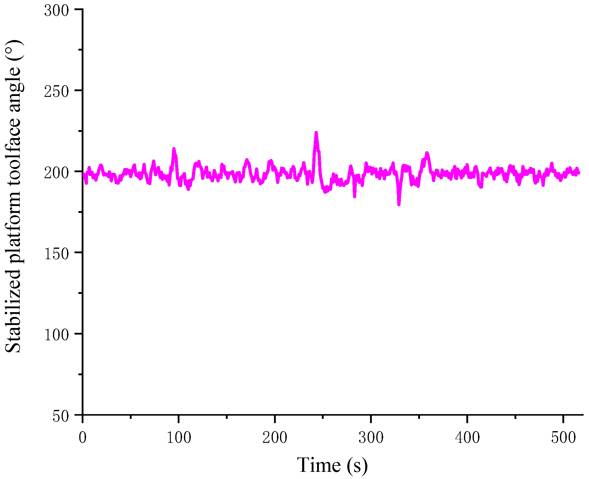
To verify the adaptability of the self-stabilizing control strategy to the drilling fluid flow rate, an adjustment was made to the drilling fluid flow rate during the experimental process. The experimental results are illustrated in
Figure 10. The experimental conditions were as follows: a drill collar rotational speed of approximately 88 rpm, a drilling fluid flow rate of 46 L/s, an inclination angle of approximately 1°, and the set value of the stabilized platform toolface angle was 200.7°. At 238 s, the drilling fluid flow rate was adjusted from 46 L/s to 65 L/s. Subsequently, the toolface angle of the stabilized platform experienced an oscillation with an amplitude of approximately 25°. After an adjustment time of about 20 s, the stabilized platform returned to a stable control state. The experimental results in
Figure 8 demonstrate that the self-stabilizing control strategy was able to adapt to the changes in the drilling fluid flow rate.
5. Conclusions
In this manuscript, the adaptive backstepping control was studied for a stabilized platform of a rotary steerable drilling system. The state–space model of the stabilized platform system was first established, and an adaptive backstepping control law was designed based on this model. Second, an online estimation method of the balancing torque and the velocity-angle control switching strategy was proposed. In addition, by combining the backstepping control law, drilling fluid flow adaptive law, and velocity-angle control switching strategy, the self-stabilizing control strategy of the stabilized platform was established. Finally, the drilling simulation experiments verified the effectiveness of the self-stabilizing control strategy. The conclusions of this paper are as follows:
- (1)
According to the numerical simulation results, the steady-state oscillation amplitude of the adaptive backstepping control method was about ±2°, and this did not increase with an increase in the drilling fluid flow rate, which outperformed the PID control method.
- (2)
The drilling simulation experiments demonstrated that the self-stabilizing control strategy could achieve a stable control of the stabilized platform at different toolface angle set values and drilling fluid flow rates.
Additionally, we must admit that the limitation of the self-stabilizing control strategy was in the fact that the controller parameters did not adapt to the changes in the mechanical structure. In the future, the proposed control method could be combined with neural networks; then, the controller parameters will have the ability to adapt to the effects of external disturbances and changes of structural parameters, which would further enhance the system’s adaptability.


