1. Introduction
The high cost of energy resources and environmental pollution are increasingly urgent global problems that are stimulating the development of energy-saving technologies. To reduce the energy consumption of a machine, it is necessary either to increase the efficiency of the components or to re-use energy that is lost that is lost during operation by regeneration.
Worldwide, energy efficiency and energy conservation are important practical research topics in technological machinery and equipment. Reliability is a significant quality of machines, mechanisms, drives, technological equipment and their component parts, including hydraulic motors. Reliability is assured by carrying out resource tests, the results of which reveal the characteristics and properties of materials, components and working fluids that are used in the manufacture of hydraulic cylinders and during operation. One of the practical ways to determine reliability is bench testing.
Analysis of the methods of creating a load during testing of hydraulic machines has shown that they are based on the use of additional sources of working fluid flow, dissipative forces and inertia forces [
1,
2,
3]. This approach to testing is very resource-intensive due to the lack of useful work; therefore, the power consumed by the drive of the stand must be reduced.
Bench tests of various machines are increasingly used because they are more economical compared to polygonal tests or tests in real operation, where the process of monitoring and removing various operational parameters becomes more complicated. The resource assessment of the tested hydraulic machine during bench tests can be carried out in a shorter time and with more complete and reliable results. In the process of resource testing, it is necessary to standardize the temperature regime and the nature of the load. For hydraulic cylinders, these required parameters can be set during testing. When conducting resource tests on the stand, it is necessary to work out a certain number of cycles with loading according to a certain program.
Resource tests are the longest in terms of time and energy consumption; in addition, the test equipment must have an automatic control and management system, since tests can take up to three months of continuous operation.
An analysis of pertinent literature showed the authors’ interest in the regenerative drive systems of such stands. Examples of a regenerative hydraulic drive system consisting of a three-chamber hydraulic cylinder and a hydraulic circuit of the main drive are given in [
4,
5]. Such a regenerative drive system reduces the load on the hydraulic pump during operation, thereby reducing energy consumption.
There is information in the literature about hybrid energy recovery systems that operate when lowering the excavator boom by recharging batteries with the hydraulic pump–motor system, which is active when lowering the hydraulic cylinder providing the drive for the generator [
6,
7].
This method of energy recovery in mobile work machines has proven itself well. The electric power recovery system consists of an electric generator motor, an inverter, a DC-to-DC converter and a battery, as well as, in some cases, an electric two-layer capacitor [
8,
9,
10]. Alternatively, with a decrease in mass, potential energy causes a hydraulic machine to rotate like an engine, and an electric machine acts as a generator controlled by a frequency converter [
11].
It can be concluded that there is a fairly high level of interest in the use of regenerative drive systems for test stands that permits the creation of a load and enables the return of part of the spent energy back to the test system; however, to date, such systems have not been studied sufficiently.
Therefore, the research, design and calculation of regenerative drive systems for test benches of volumetric hydraulic machines are still relevant and important [
12,
13].
The analyses conducted in the literature aimed at the study of drives and test bench systems, taking into account the possibility of reducing the resource intensity of their tests, having shown that the most economical and resource-saving method is the use of regenerative drive systems with simultaneous creation of a load on the object and partial return of the converted energy to the test system [
14,
15,
16]. However, this method is not without drawbacks. The test system provides for the presence of additional flow sources that provide pressure in the pressure line of the stands, which complicates the energy consumption system and is not economical from the point of view of resource intensity.
An analysis of studies on energy-saving systems in hydraulic drives shoed that such examples are not suitable for use in the GMP service life test bench of plunger hydraulic cylinders.
An assessment of energy-saving drive systems showed that the use of a regenerative system reduces the energy consumption of the primary source due to the circulation of energy inside the hydraulic pump–hydraulic motor–hydraulic pump system; thus, energy recovery occurs.
Studies aimed at identifying more rational ways to create the load of hydraulic machines and determining the methods of their modeling during design have shown that the most interesting are hydro-mechanical regenerative drive systems [
17,
18]. However, no theory or methodology for calculation have been proposed with respect to the design of such systems. The insufficient level of coverage of this issue in the literature determined the purpose and objectives of this paper. The aim of this work is to increase the efficiency of the regenerative drive system of the test bench of volumetric hydraulic machines by improving the theory and methodology of its calculation and design.
2. Materials and Methods
As part of the solution of the issue, a theoretical analysis of the regenerative stand was carried out, and a drive of the test bench for a rotary hydraulic machines was proposed [
12].
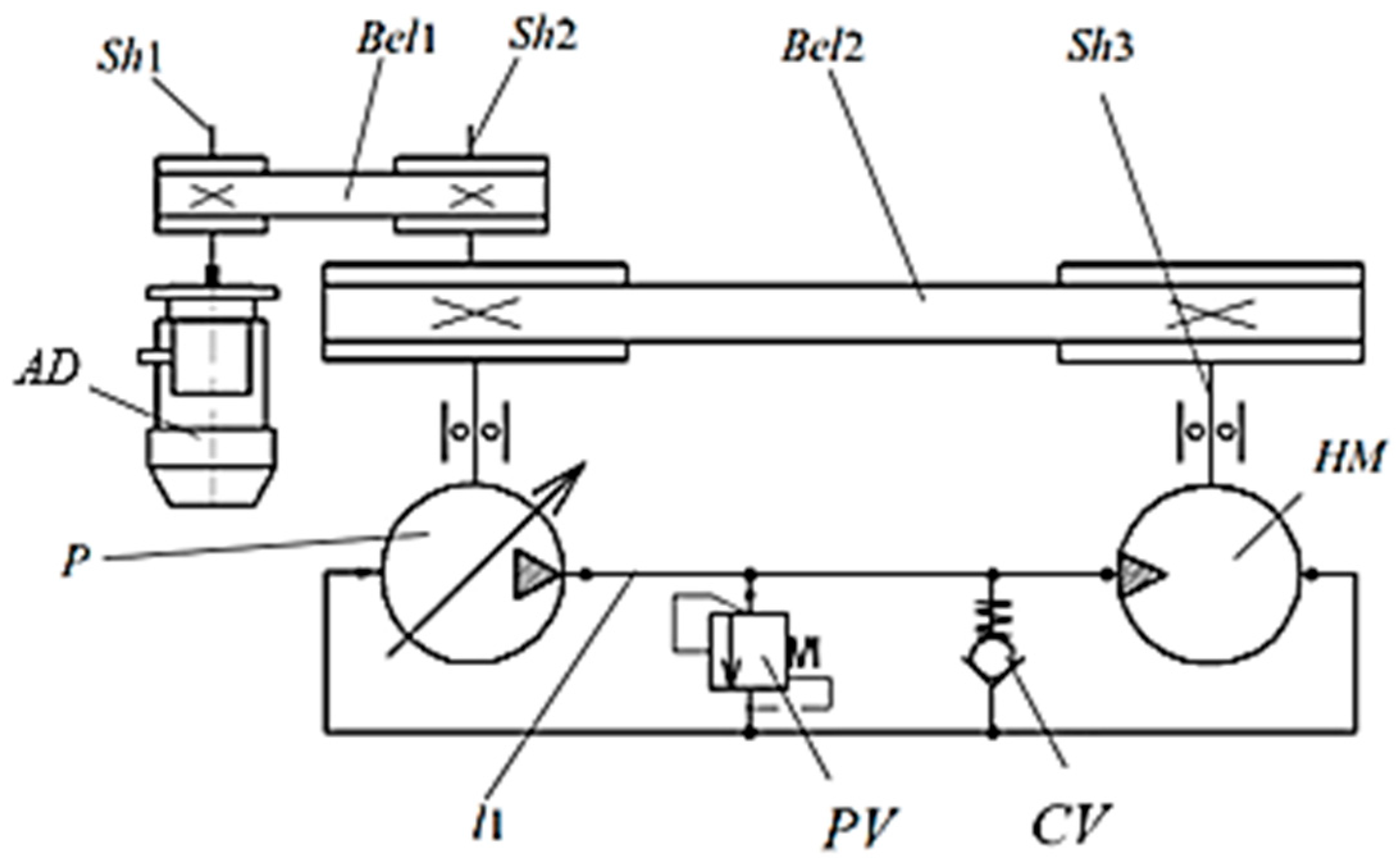
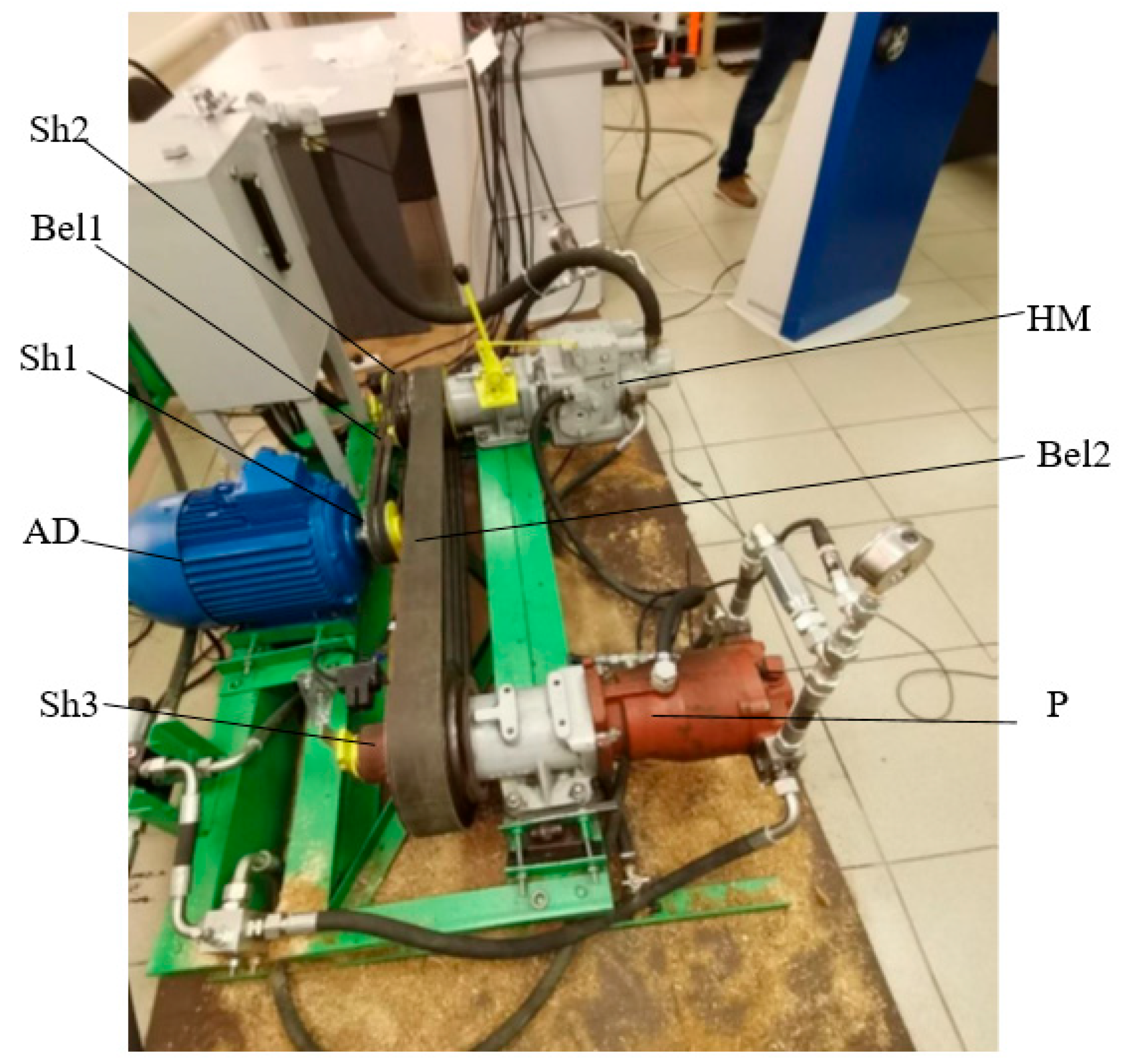
Figure 1 shows a schematic diagram of the system under study.
Let us consider the principle of operation of the circuit of the regenerative drive of the test bench of rotary hydraulic machines. From the three-phase network, current is supplied to the asynchronous motor indicated as AD in the diagram. In an asynchronous motor, the current is converted into mechanical rotational energy of shaft Sh1 and fed to mechanical transmission Bel1, allowing the rotational energy to be transferred to shaft Sh2, where it is summed with the mechanical rotational energy from shaft Sh3 of the hydraulic motor (HM) brought to shaft Sh2 through mechanical transmission Bel2. In turn, the hydraulic pump (P) converts the mechanical energy of rotation of shaft Sh2 into the energy of the hydraulic flow. The energy of the flow along pressure line l1 is transmitted to the input of the hydraulic motor (HM), which, in turn, converts the energy of the hydraulic flow into the mechanical energy of rotation of shaft Sh3. The pressure increase in the pressure line is controlled by a safety valve (PV). The CV check valve is used to ensure the unloading of the hydraulic system at the time of its output to the specified modes.
In order to evaluate the energy consumed by an electric motor, as well as to identify its effect on the quality of transients of a regenerative system, we propose the use of a mathematical model of an asynchronous electric motor in the following system of expressions:
where
,
,
and
are the flow coupling of the stator and rotor decomposed in an orthogonal system (
x-y);
and
represent the voltage applied to the stator windings decomposed in an orthogonal system (
x-y);
and
represent the resistance of the stator and rotor windings, respectively;
is the synchronous frequency of rotation of the stator field;
is the frequency of rotation of the motor shaft;
is the number of pairs of poles of the electric motor;
is an intermediate function, where
and
are the inductance of the stator windings and the mutual inductance between the rotor winding (one phase) and the stator windings (all phases), respectively, and
is the scattering inductance of the rotor winding;
is the voltage in the phase circuit;
is the torque transmitted by the electric motor to the shaft (I) of the mechanical system; and
t is time. All values are given in SI units.
Equations describing the change in the rotational speed of the corresponding shafts are presented as follows:
where
is the speed of rotation of the shaft of the hydraulic pump;
is the speed of rotation of the shaft of the hydraulic motor; ∑
MI, ∑
MII and ∑
MIII are the sums of torques given to the corresponding shafts; and
JI,
JII and
JIII are the values of the central reduced moments of inertia for the corresponding shafts.
A dynamic model of the elastic-dissipative state of the elements of the hydraulic drive sections is proposed for the analysis of the hydromechanical regenerative drive system of the test bench of hydraulic machines, accounting for energy losses, and to monitor the functioning of the hydromechanical system. The dynamic model is based on the concept of volumetric stiffness for the corresponding energy state [
19,
20].
The dynamic model was developed using the theory of volumetric stiffness [
19], according to which the pressure increment (
) at any point (in an elementary volume) of the hydraulic system during operation can be determined by the following equation:
where
and
are the sum of all instantaneous (
j-th) flow rates of the working fluid entering and exiting the considered (
i-th) volume of fluid during
dt, respectively, and
is the instantaneous reduced coefficient of volumetric stiffness of the selected section of the hydraulic system, which is determined by the following formula:
where
represents the coefficients of the volumetric stiffness of the elements of the selected section of the hydraulic system, which, in accordance with the chosen methodology, we determine according to the following expression:
where
is the volume of the element of the selected area, and
is the modulus of elasticity of the working fluid in the considered area.
It is known that the modulus of elasticity of the volume of the working fluid largely depends on the pressure and the percentage of gas undissolved in it in its allocated volume. Therefore, the instantaneous stiffness of the volume of the working fluid of any section of the hydraulic system can be calculated by taking into account changes in its modulus of elasticity.
where
k is the content of undissolved air in the allocated volume of the working fluid (%),
is the modulus of elasticity of a liquid at atmospheric pressure and
is the value of the pressure acting in the allocated volume of liquid.
Working fluid consumption (incoming, ; outgoing, ) of the i-th area of the liquid volume corresponding to the considered types of flow sources can be calculated using the following expressions:
- -
For hydraulic resistances:
- -
For mechanical flow sources:
where
is the instantaneous value of the hydraulic loss coefficient for each
j-th hydraulic resistance calculated by known methods;
is the area of the passage section of the corresponding hydraulic resistance;
is the change in the speed of the allocated area of the mechanical element;
is the area of the passage section of the corresponding incoming or outgoing hydraulic resistance from the
i-th allocated volume of liquid during
; and
is the density of the allocated volume of the working fluid, the current value of which can be calculated as:
where
is the density of the working fluid of the allocated volume under normal conditions.
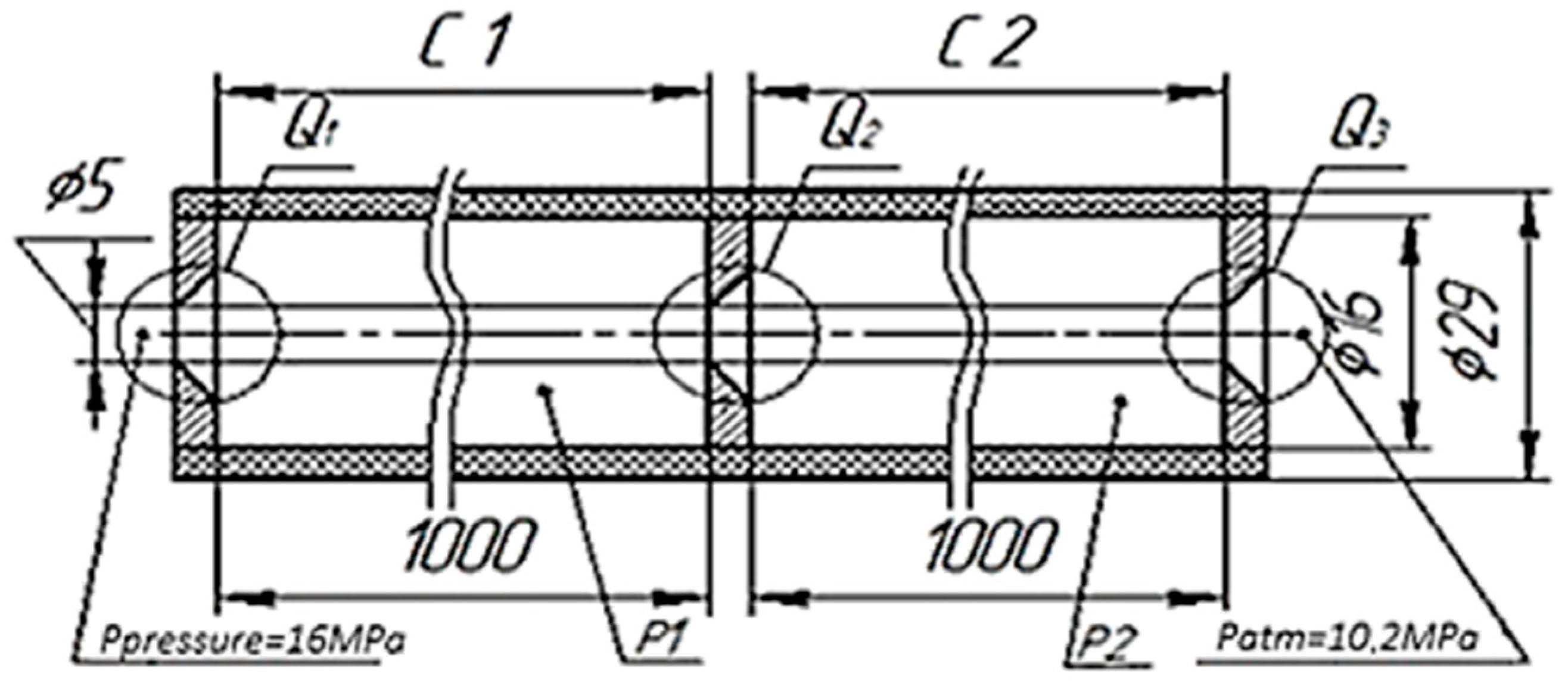
Using the proposed dynamic model of the elastic-dissipative state of the sections of the elements of the hydromechanical system, we calculate a system consisting of two sections: c1 and c2 (
Figure 2). The volume of the reduced stiffness is limited by two hydraulic resistances of the “hole with a sharp edge” type. The parameters under normal conditions accepted for calculation are as follows: The elastic modulus of the wall material is 3200 MPa, the elastic modulus of the working fluid is 1500 MPa, the percentage of undissolved air is 3% and the density of the working fluid is 900 kg/m
3. The geometric parameters and the design scheme are shown in
Figure 2.
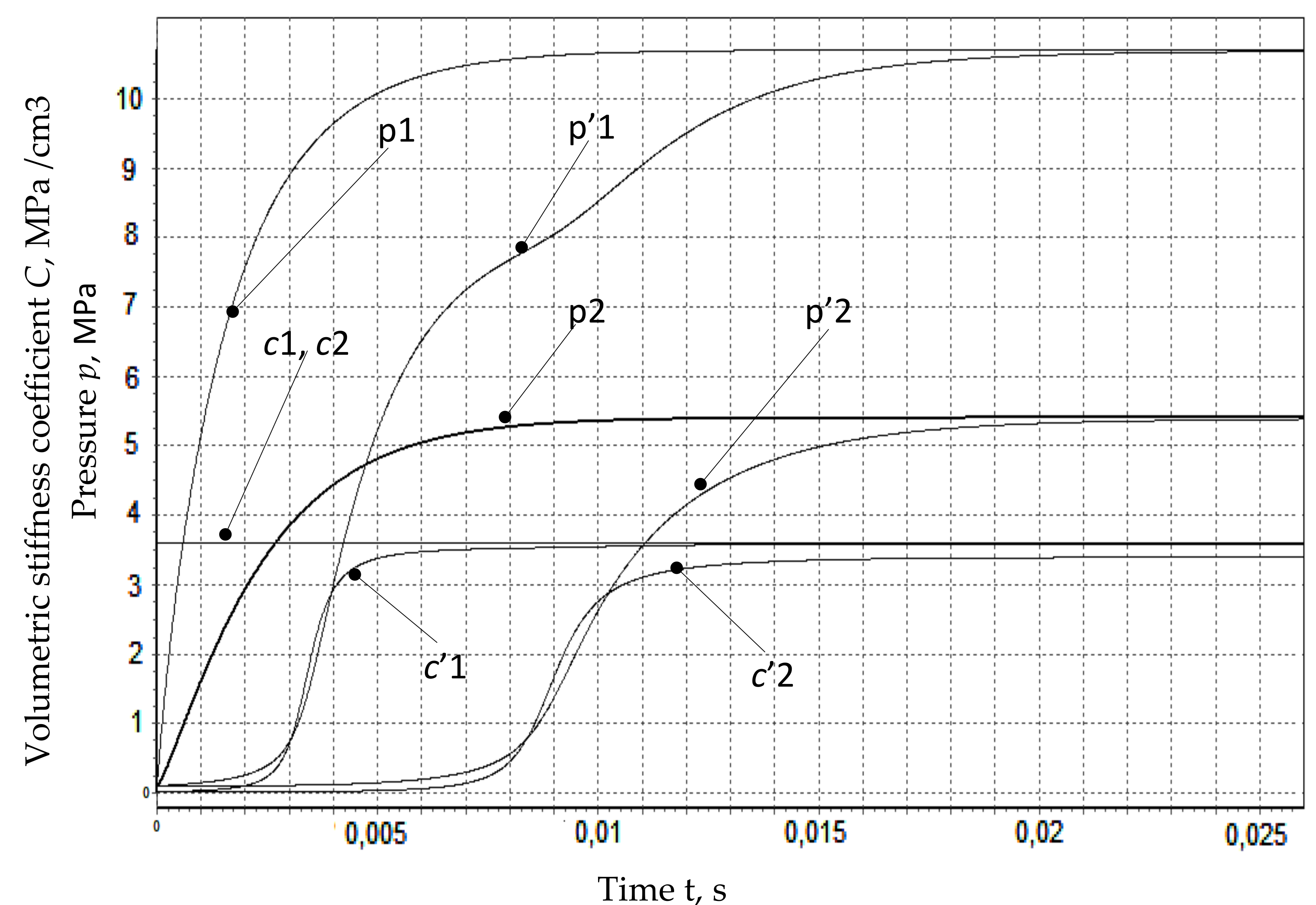
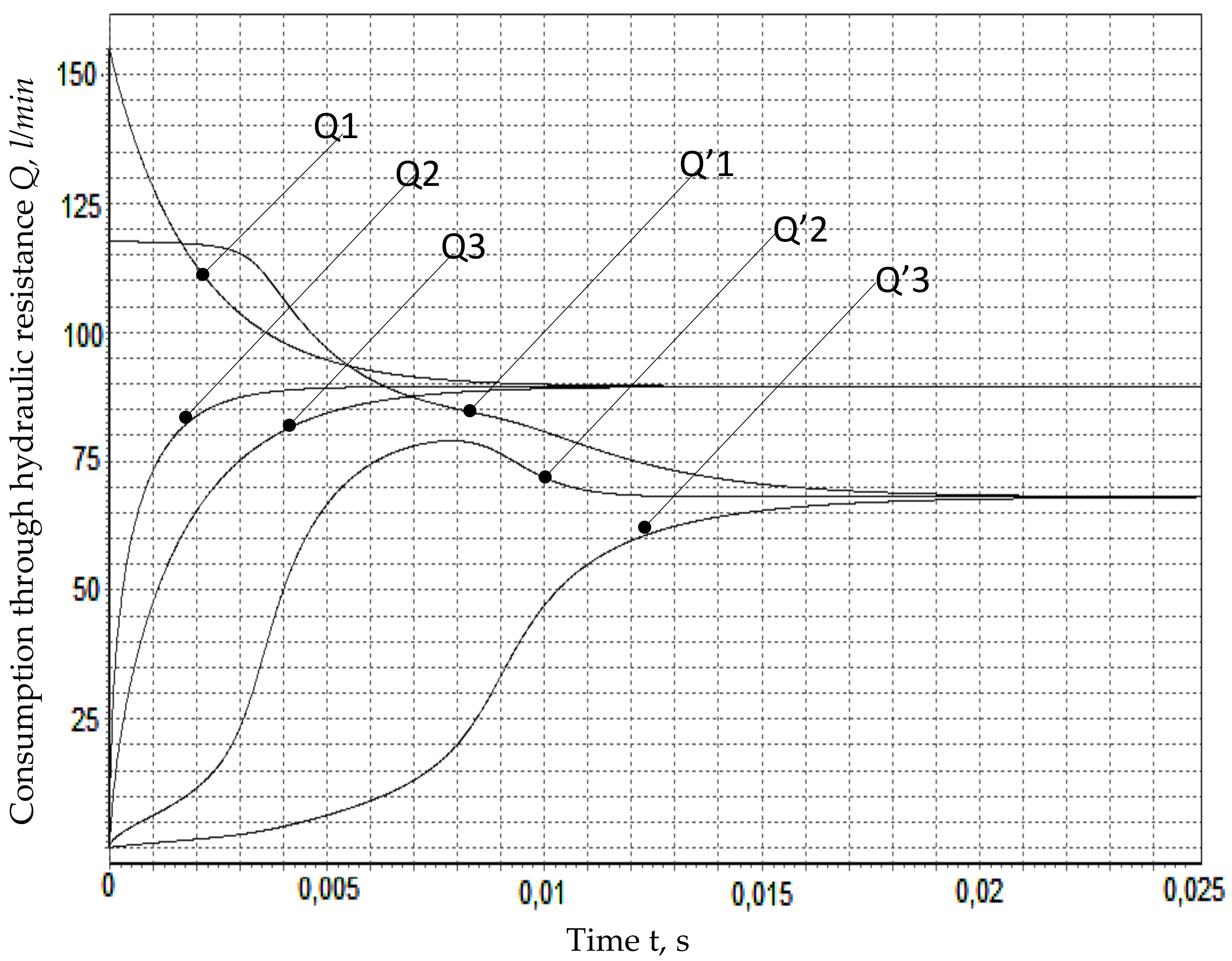
In the proposed model, to simplify calculations, we do not take into account the process of heat exchange of energy carriers of the system with the environment and possible changes in some values from fluctuations in the temperature of the working fluid. The obtained values are indicated in
Figure 3 and
Figure 4 without a with a stroke. Also, changes in the properties of the working fluid from instantaneous pressure were not taken into account, with the coefficient of hydraulic resistance assumed to be 0.7. The values obtained according to the proposed calculation are shown in
Figure 3 and
Figure 4 with a dashed symbol.
The obtained calculation results confirm a significant degree of dependence of the intensity of the increase in flow rates through hydraulic resistances on changes in their reduced volumetric stiffness coefficients. An increase in the density of the working fluid leads to an increase in pressure and a decrease in the flow rate of the working fluid.
One of the features of the testing process of technical systems, including hydraulic machines, is that there is no generalized criterion for evaluating the efficiency of the testing process.
The efficiency coefficient, in its classical formulation, cannot be accepted as an assessment of the cost-effectiveness of the test process. Since there is no “useful power” during testing, the usefulness of testing lies in obtaining the test results themselves; therefore, it is necessary to expend (lose) energy for testing.
In this paper, as a criterion for evaluating the efficiency of the testing process, we use the “test energy efficiency coefficient”, which is equal to the ratio of the power passing through the tested hydraulic machines during their testing to the power spent on testing.
The formula of the “test energy efficiency coefficient” has the following form:
where
is the power supplied to the electric motor during testing, and
is the load power of the hydraulic machines being tested.
To ensure a high level of efficiency of the test process, it is necessary to create conditions under which the energy efficiency coefficient of the test significantly exceeds 1, which indicates that the power consumed during the test process is significantly less than the power required to conduct tests with a proper load.
Thus, it can be argued that the developed mathematical model of an asynchronous electric motor made it possible to obtain its dynamic characteristics and assess the impact on the operation of the proposed regenerative system as a whole. Also, the mathematical model of the regenerative drive system of the hydrostatic transmission tests made it possible to identify the main design and functional parameters that have a primary impact on its efficiency and operational performance, which makes it possible to improve the structural elements of the system by analyzing their functioning.
To accelerate and unify the calculations that determine the influence of the design and functional parameters of the regenerative drive system of the stand on the operational characteristics of the test system, a mathematical model of the stand was formed in a specially developed program using the SimInTech package. In the program, the calculation was carried out for hydrostatic transmission with the basic parameters given in
Table 1.
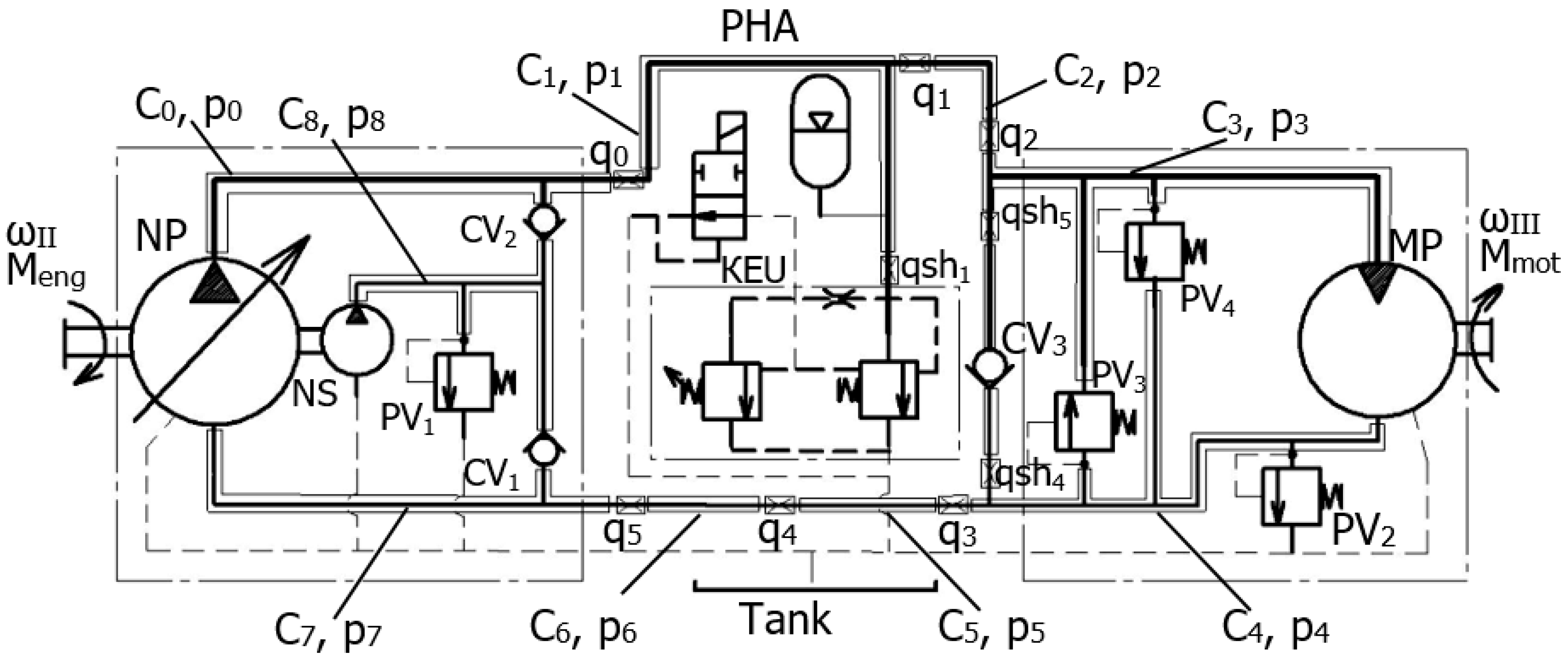
A diagram of the regenerative drive system for testing of hydrostatic transmission is shown in
Figure 5.
In the diagram (
Figure 5), the following designations are used:
Ci and
p represent the given stiffness and the corresponding pressure of the working fluid of the
i-th sections of the hydraulic system, respectively;
q0–q5 represent hydraulic resistance functions that take into account hydraulic energy losses along the length of the hydraulic supply equipment; NP is the GST pump; MP is the GST motor; NS and PV
1 are the make-up pump and the safety and check valve of the drain line, respectively; CV
1 and CV
2 are the check valves of the pressure line; PV
2, PV
3 and PV
4 are MP safety valves (the setting pressures of which re 1, 5 and 32 MPa, respectively); KEU is control valve of the KEU; and PHA is the pneumatic hydraulic accumulator.
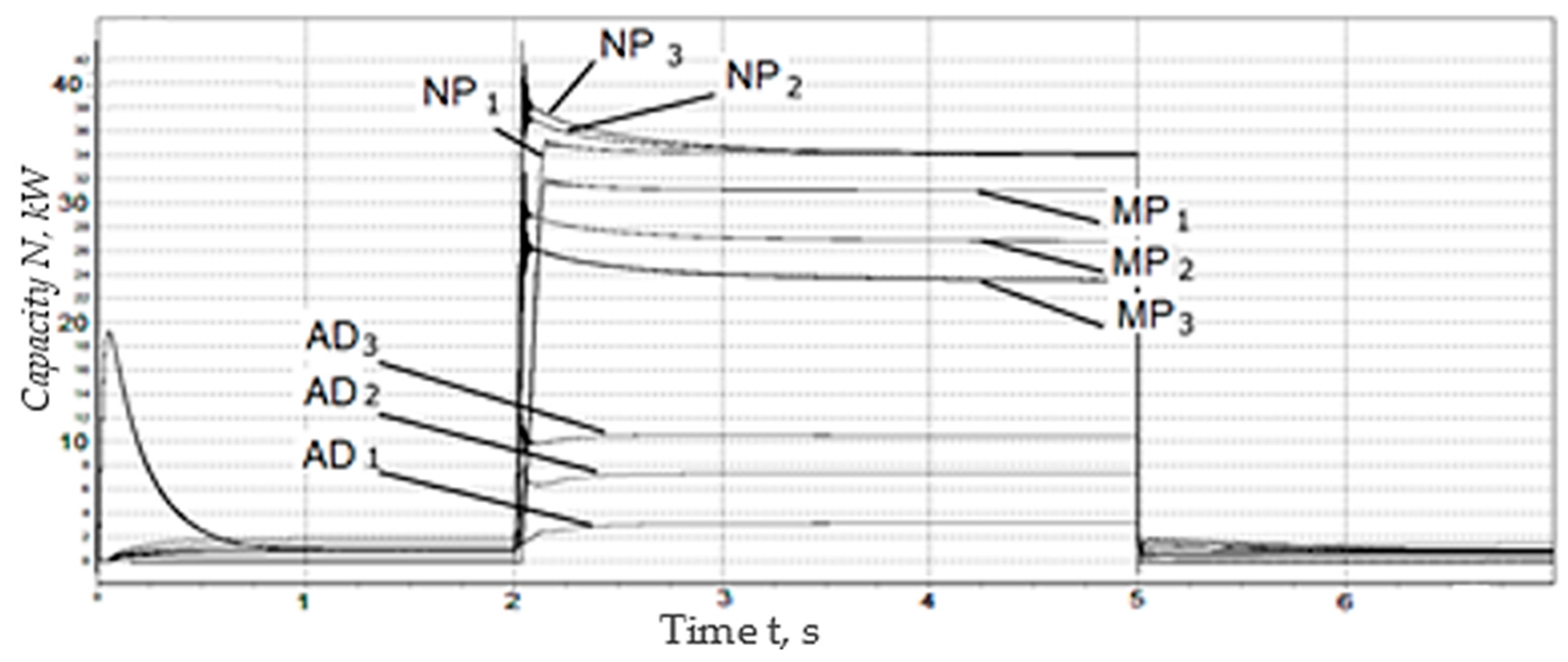
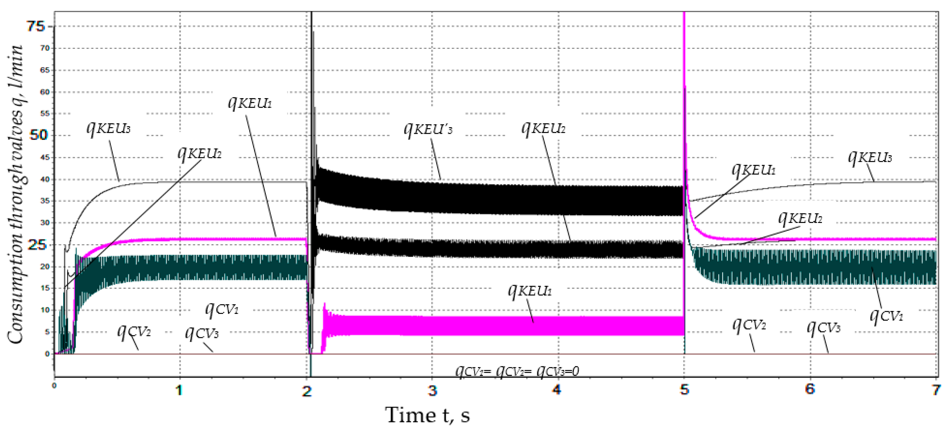
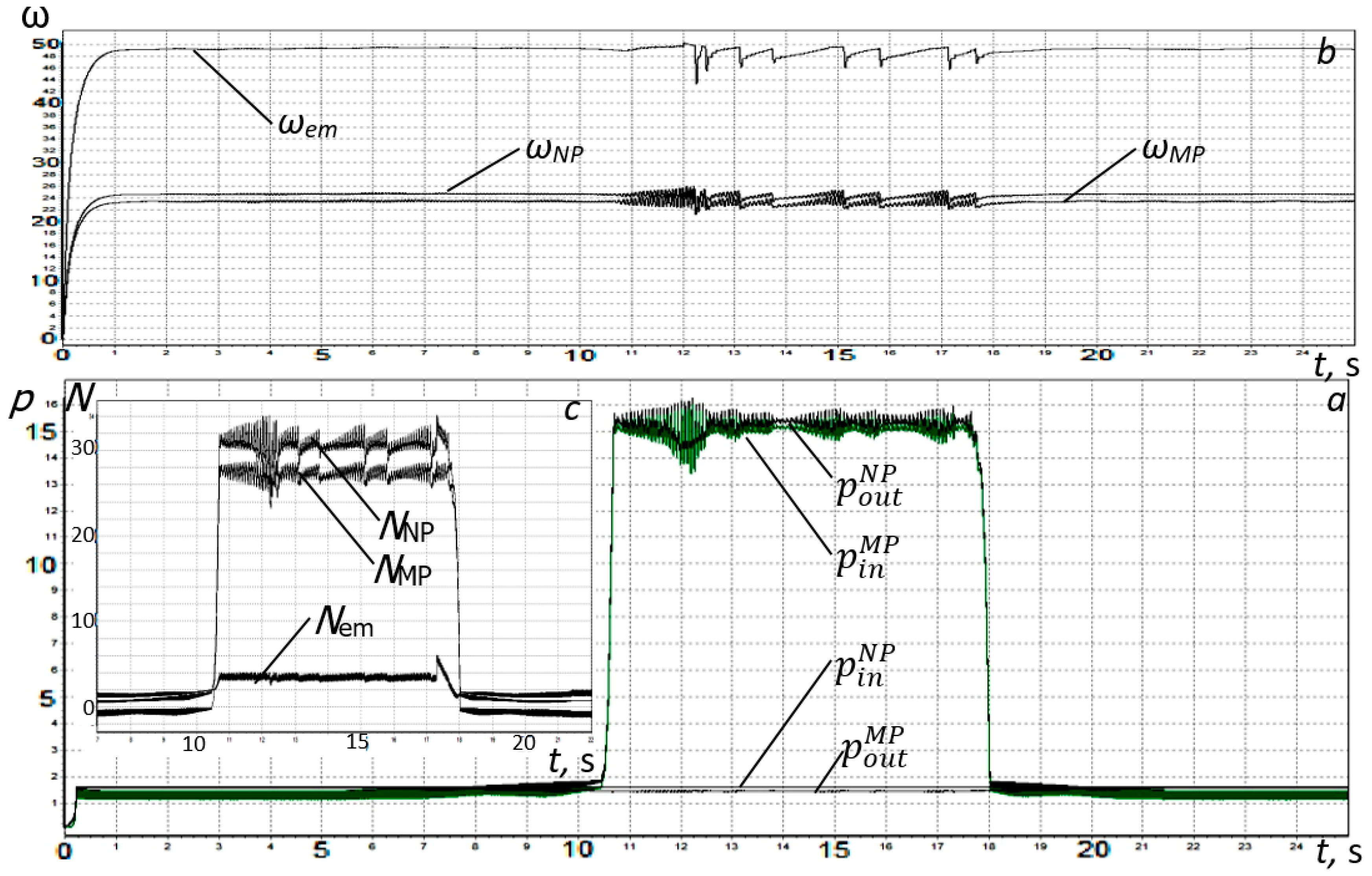
Considering the stand from the point of view of dynamic transformations of the working volumes of the pump and motor, we assume that the most informative are the power changes of the asynchronous motor, pump and motor GST, as well as the costs through the control valves of the KEU and check valves (CVs). The obtained simulation results are shown in
Figure 6 and
Figure 7. The calculations took into account that the pressure of the KEU control valve provides 16 Mpa; when t ≤ 2 and t ≥ 5, the valve is open, and when 2 < t < 5, the valve is closed.
The control of the gearbox valve ensures the output of the recuperative system to the mode after acceleration of the mechanical system.
During the operation of the test bench, the pressure in the system varies widely, which forces the modeling and calculations to take into account the change in the volumetric efficiency coefficient (
) of hydraulic machines, which is determined by the following formula:
where
is the nominal value of the volumetric efficiency of a hydraulic machine, which is assumed to be equal to the volumetric efficiency of a hydraulic machine operating at nominal pressure;
is the nominal value of the working pressure of a hydraulic machine; and
is the actual value of the working pressure.
Based on the results of the modeling of the energy efficiency coefficient of the recuperative system in an established mode, it can be concluded that with an increase in the gear ratio, the efficiency of the recuperative testing system for volumetric hydraulic machines decreases due to an increase in flow and, accordingly, power losses of the working fluid through the safety system.
Figure 6 shows graphs of changes in design capacities with an increase in the gear ratio, which entails a significant increase in the power consumption of the electric motor due to an increase in consumption and, as a consequence, loss of power of the working fluid through the KEU safety system. As a result, the efficiency of the recuperative system is reduced.
To compensate for leaks and overflows of the working fluid in the channels of the pump, motor and control valve, it is necessary that the amount of the NP pump supply sufficiently exceed the consumed consumption of the MP motor. At the same time, it should be taken into account that small values of the gear ratio (i
2) in the overflow mode of the KEU control valve may cause the pressure of the drain line to exceed the pressure in the pressure line, causing the opening of the check valve (CV) (
Figure 7). Particular attention should be paid to the sharp increase in pressure when entering the operating mode, which limits the KEU and can negatively affect the pneumatic hydraulic accumulator (PHA) being tested.
The time to enter the mode can be adjusted by gradually increasing the supply of working fluid from the NP pump to the pressure line of the system over the amount of consumption by the MP motor. This can be achieved by changing the gear ratio (
i2) or by gradually increasing the working volume of the NP pump, that is, at,
i2 =
const, or by installing a pneumatic hydraulic accumulator (PHA in
Figure 5).
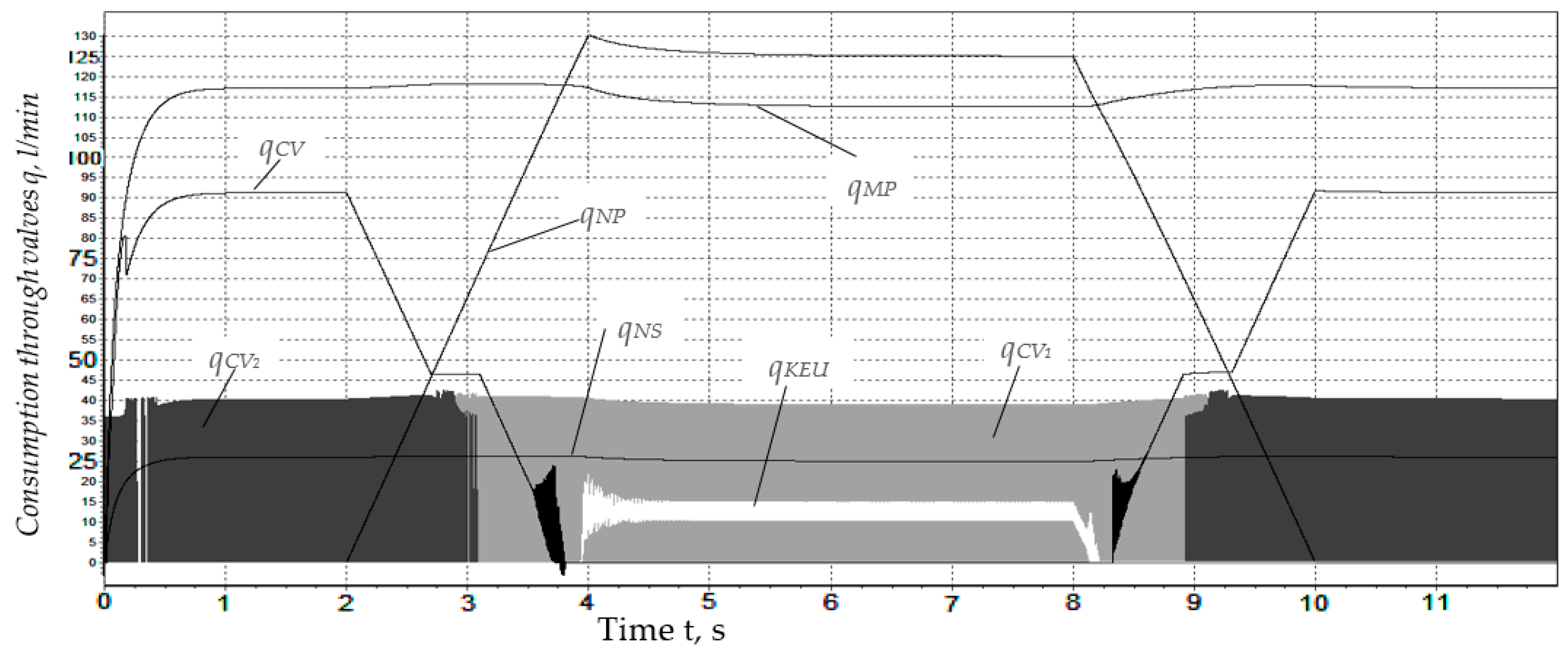
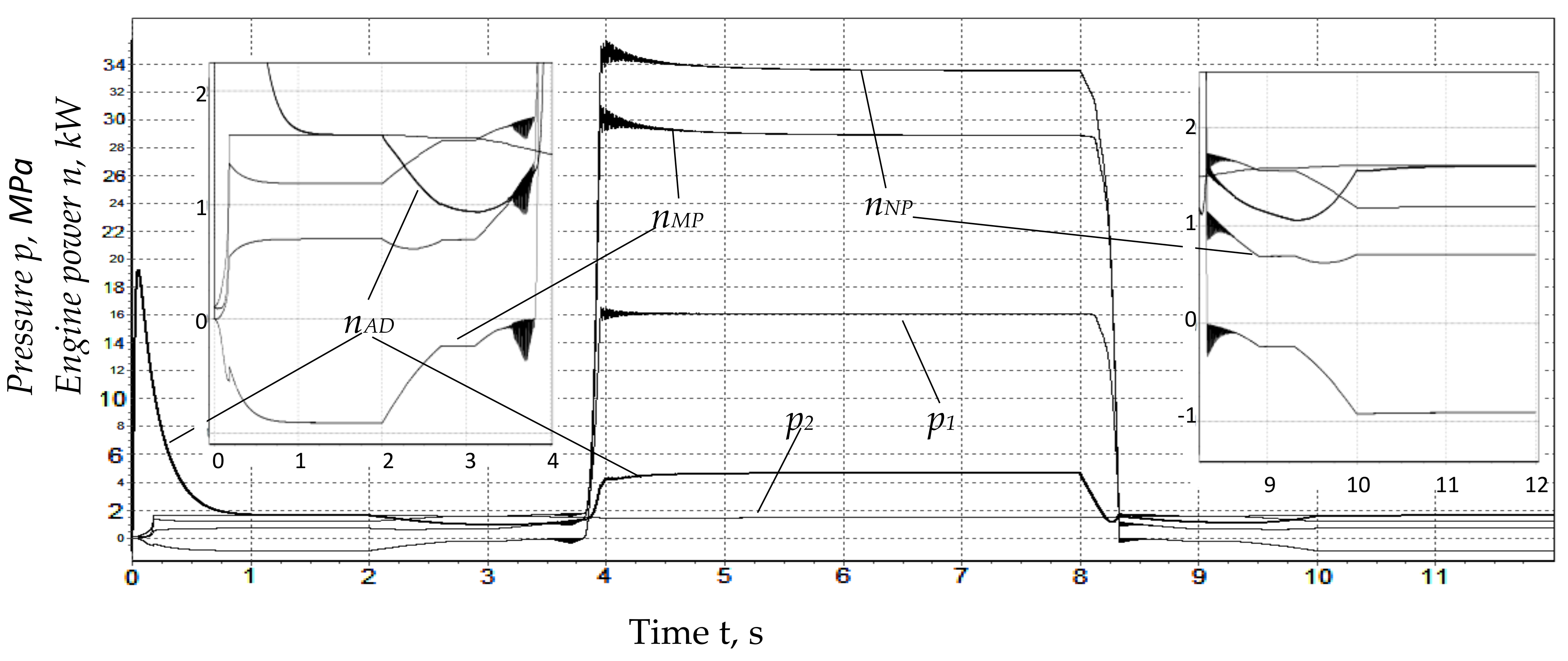
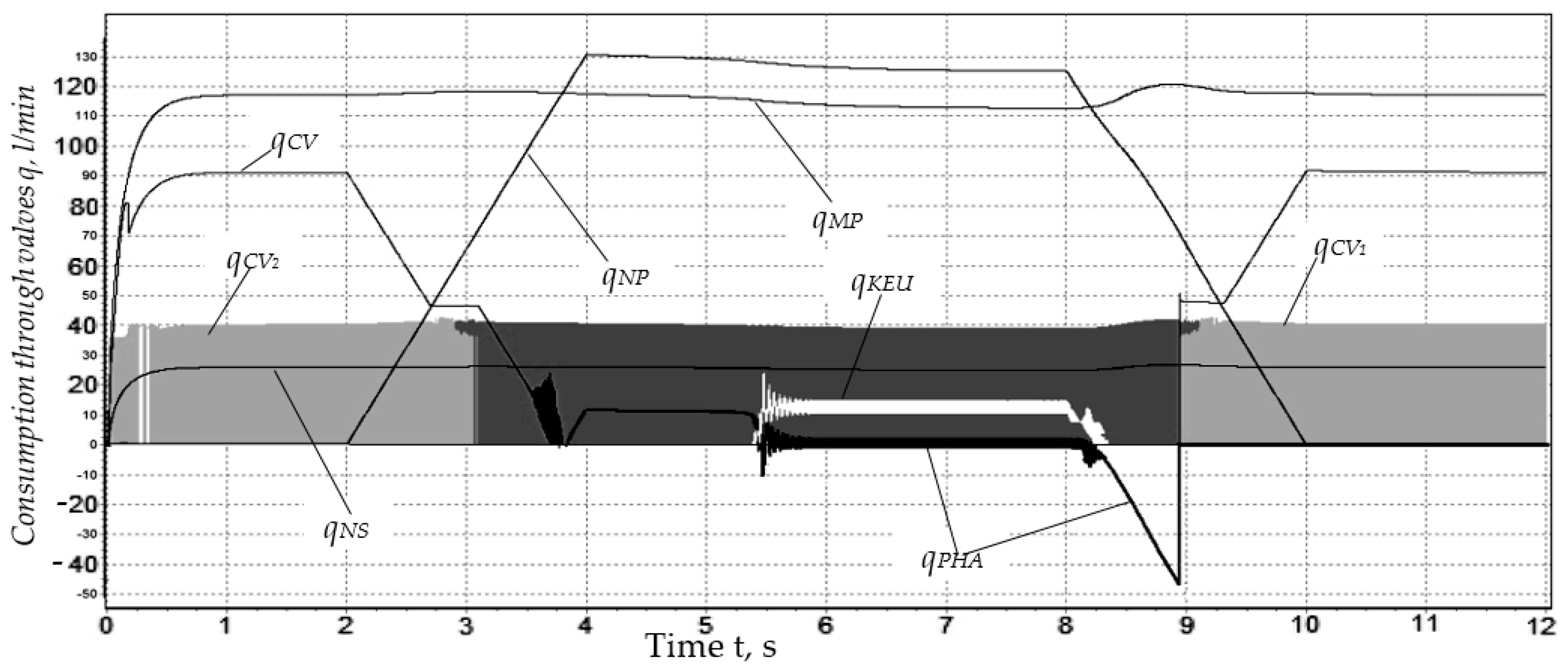
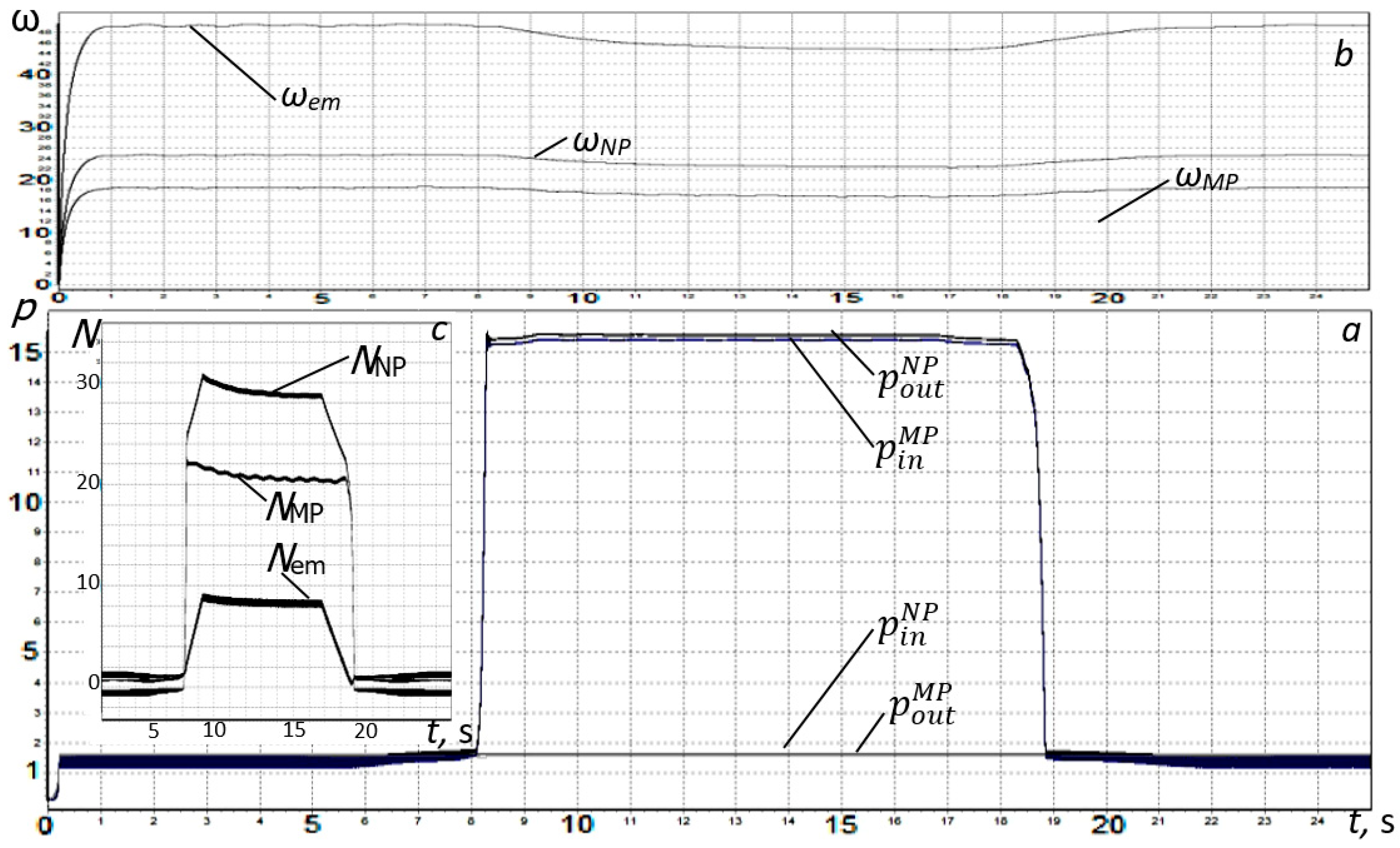
Figure 8 shows the graphical dependences of the flow rates of the working fluid of the NP pump, the NS recharge pump and the MP motor, as well as the flow rates through the control valves (KEU) and check valves *CV, CV
1 and CV
2) when the pneumatic accumulator (PHA) is switched off. The following conditions were taken into account when calculating a system with a variable working volume of NP: the KEU is in a closed state, the gear ratio is
i2 = 1.1, the pressure of the gearbox is 16 MPa, the volume of the pneumatic accumulator is 0.4 dm
3 and the charging pressure is 2 MPa. The calculation was carried out for cases with the PHA disconnected and with the PHA connected to the pressure line of the stand. The calculation results are shown in
Figure 8,
Figure 9,
Figure 10 and
Figure 11.
In both cases (with the PHA disconnected and connected), the working volume of the NP pump remained equal to zero for the first two seconds; then, in the time interval from 2 to 4 s, it linearly increased from 0 to 90 cm3 and remained equal to 90 cm3 for up to eight seconds, after which it linearly decreased to zero and did not change further.
The calculation results are shown in the form of graphs in
Figure 8 and
Figure 9. According to the graphs, with zero pump supply, the motor begins to work as a hydraulic pump. This process occurs due to the opening of the check valves (CV
1 and CV
2) and the recharge of the pressure line with the help of NS. With a smooth change in the flow rate of the working fluid supplied by the hydraulic pump, as well as the operation of the check valves, switching from hydraulic pump mode to hydraulic motor mode is permitted. After that, the energy recovery process takes place. This process is accompanied by a sharp pressure surge due to the presence of volumetric stiffness in the working fluid. The values of the coefficient of reduced volumetric stiffness of the working fluid are also taken into account in mathematical modeling. Thus, in order to eliminate sudden jumps in pressure in the system and to ensure the smoothness of its change, it is necessary to reduce the reduced volumetric stiffness of the working fluid in the pressure part of the system. Such a situation can be ensured by installing a pneumatic accumulator in the system.
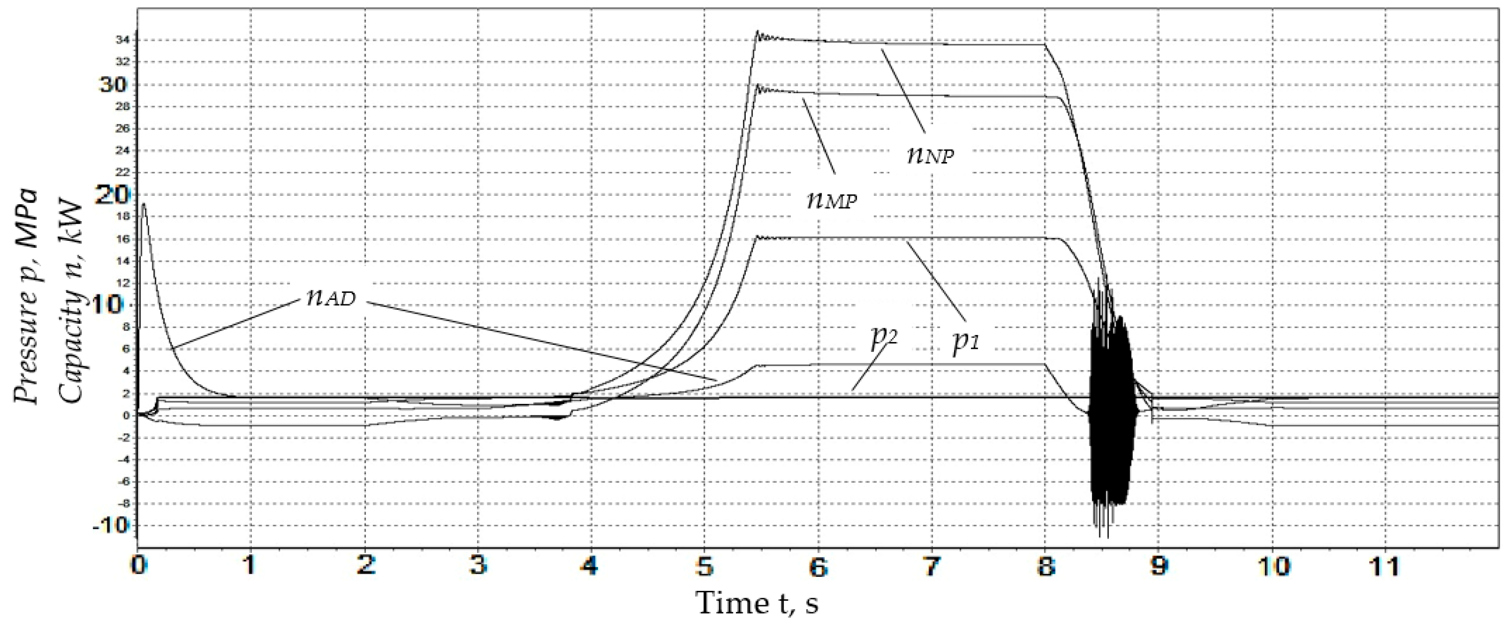
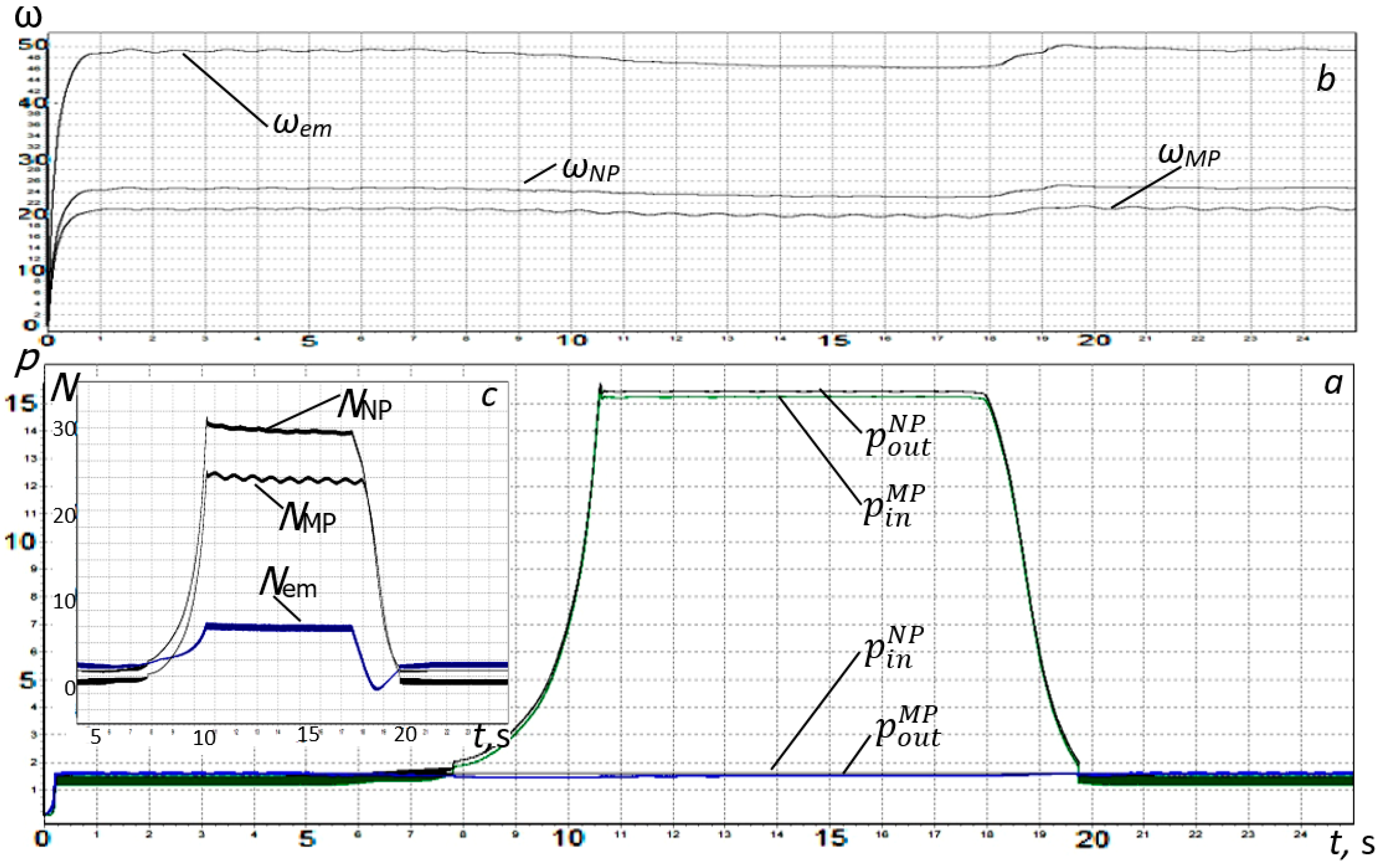
Graphs displaying the calculation results of a recuperative system with an installed pneumatic accumulator are shown in
Figure 10 and
Figure 11.
When the gear ratio changes, the difference in the flow rates of the working fluid of the corresponding lines increase, which leads to an increase in the filling rate of the working volume of the pneumatic accumulator. Therefore, the working volume of the pneumatic hydraulic accumulator should be selected according to the need to ensure the time for the recovery mode of operation of the hydromechanical system to reach a given pressure level in the pressure line. When removing the system from the regenerative mode of its operation, the pneumatic accumulator maintains the pressure of the working fluid in the pressure line for some time. The process of removing the system from the regenerative mode leads to a short-term excess of the power over the consumed hydraulic pumps (NP and NS), which is due to the return of the working fluid to the test system due to the continued operation of the MP.
In this situation, the pneumatic accumulator, together with the pressure line, acts as an energy source. An additional energy source is used by the system to switch to a regenerative mode due to a short-term excess of the angular velocity of rotation of the rotor of an asynchronous electric motor over the angular velocity of rotation of the magnetic field of the stator.
Analysis of the obtained results showed that the main functional and design parameters of the regenerative drive system are primarily influenced by the elastic-dissipative properties of the elements of energy sources and consumers of the flow of the hydraulic system, that is, the gear ratio of the mechanical transmission and the elastic-dissipative properties of the hydromechanical system.
Based on this study, a method was developed for calculating the rational parameters of the regenerative drive system of the service-life test bench of volumetric hydraulic machines, which makes it possible to increase its efficiency.

 ,
, 


