1. Introduction
A significant part of modern technical products and systems includes parts and assemblies produced by casting methods that include, for example, valves, valve manifolds, heat sinks, electric motor housings, cylinder blocks, bushings, gears, gear housings, thermocouple housings, housings of rotary encoders, etc. This is due to the fact that modern parts with complex geometric shapes, obtained through the application of modern optimization methods, can be produced economically with only a small number of technological processes, one of which is casting [
1,
2,
3]. For industrial application, and especially for large-scale production, machine casting in metal molds is commonly used. The most often used equipment for this process is horizontal high-pressure casting machines.
The automation of auxiliary operations in high pressure die casting is a current and prospective problem due to extremely harmful working conditions, hard and unattractive monotonous work in a highly aggressive working environment, and high temperatures. These factors pose a number of problems for companies—economic, technical, social (e.g., providing the necessary personnel), related to energy efficiency, etc. [
4,
5,
6,
7]. The automation of foundry operations leads to increase in quality and productivity; reduction in waste and cost; improvement in technical safety and working conditions; reduction in emissions of harmful substances that pollute the soil, water, and air; and reduction in energy costs per unit of production. In the general case, progressive changes are made in the nature and content of work, related to an increase in its intellectuality, qualifications, pay, and the culture of production. All this leads to the improvement of the social climate in the companies, the improvement of their corporate image, as well as the increase in their competitiveness in the labor market.
One of the main auxiliary operations during high-pressure die casting is the extraction of the casting from the mold. In practice, both universal (most often anthropomorphic) and specialized industrial robots [
8,
9,
10,
11] are used to automate this operation. In a number of cases, universal robots have excess functions in terms of load capacity, number of degrees of mobility, flexibility, speed, acceleration, positioning accuracy, etc., which are not used rationally. This leads to a decrease in the effectiveness of their application. In addition, universal robots are characterized by a relatively high cost, the need for a larger installation area compared to specialized robots, and greater energy consumption [
12] due to the excess of degrees of mobility. Their operation and maintenance also require special qualifications, knowledge, and skills from staff. On the other hand, specialized robots offer opportunities to optimize these parameters [
13,
14].
Specialized robots, for the automation of auxiliary operations during high-pressure die casting, are available both from casting machine manufacturers and from companies that only manufacture this type of robots. Market analysis shows that the design and production of such specialized robots are current and promising, and their implementation represents a wide market niche, as thousands of non-automated casting machines are in operation worldwide. For example, OSKAR FRECH alone currently has more than 4000 machines sold that are not fully automated [
13]. An additional market for the realization of the specialized robots is the tending to new machines that are being produced.
The stage that requires the greatest responsibility in the process of designing a robot extractor is conceptualization. During this stage, the optimal structural variant of the robot is created and selected. The selected variant predetermines, to the greatest extent, the effectiveness of the designed system. This stage is particularly important, as it is the basis of embodiment design; correcting the chosen solution at a later stage is also associated with significant costs.
An analysis of the specialized literature shows a relatively small number of developments dedicated to the problem of choosing the optimal structural variant of robots for extracting castings [
13,
14,
15]. The known publications also have some drawbacks. The first drawback is related to the fact that they consider and evaluate a limited number of possible variants—usually 2–3 variants, per extractor. This greatly reduces the probability of finding the best solution. The second drawback is related to the choice of criteria for evaluating the variants. Technical criteria are mainly used—number of controllable axes, speed, presence of a closed energy loop, absence of an energy passive unit, branching of the loop into two branches from the input unit, etc.—which take into account only the functional capabilities of the robot. But for a good market realization, not only the functional capabilities are important, but also the convenience of service and repair; the technological cost, including the costs of energy, machines, basic, and auxiliary materials; tools and equipment for the production of the robot; and the costs of energy in the process of exploitation. The reduction in costs for materials and energy acquires particular importance for the conditions imposed by the world energy crisis: a decline in production and difficulties with the supply of parts and raw materials, the need for economical use of natural resources, and environmental protection.
In addition, there is a contradiction between the huge number of theoretical developments describing mathematical methods for optimization [
16,
17,
18,
19,
20] and their application for solving the problem under consideration. This is due to both the lack of information and/or limited access to the latest modern methods, as well as the sometimes complex mathematical apparatus and “unfriendly” user interface of software products for the robot builders. In addition, the developments and application software for designing and choosing an optimal structural variant are “know how” for the companies engaged in such activities, and the scientific research units specialized in this field strive to sell the achieved results as special developments to the interested manufacturers.
Therefore, the present paper is dedicated to the problem of computer-aided choosing of an optimal structural variant of a robot for extracting castings from die casting machines.
2. Development of the Set of Possible Structural Variants
2.1. Analysis of the Extracting Process
The process of extracting the casting begins after the technological process of casting is completed and the mold is opened by the movable plates of the casting machine. It is necessary for the extractor to enter the area between the plates of the casting machine and approach the correct position to grip the casting. The latter has a specially designed element which allows for reliable gripping. After the casting is gripped, with a synchronized motion of the robot and the mold’s ejectors, the casting is removed from the mold. During removal, considerable forces are required because, despite the spraying procedure and the geometry adapted to the technological process, it is possible for the part to acquire significant adhesion to the tool. The casting held by the robot is moved out of the working area of the casting machine and transported to an unloading position. At the unloading position, the casting is released from the robot and proceeds to the next stage of processing.
2.2. Development of a Functional Model of a Casting Extraction Robot
In order to develop the functional model of the robot, the latter is considered a technical system [
21,
22] and is initially represented as a “black box” (
Figure 1). The general function of the robot is defined as “Extract casting” after the die casting operation is finished. The implementation of the general function of the robot is related to providing a certain set of inputs (
Figure 1 and
Table 1):
Casting—this is the casting that was cast during the technological process and must be extracted from the mold;
Gripper—a tool for gripping the extracted casting;
Power—source/sources of energy powering the robot’s motors;
Control signals for the actuators—signals from the control system to the motors to execute the movements of the robot’s cycle.
The inputs of the system are converted by the overall function into a certain set of outputs (
Figure 1 and
Table 1):
Extracted casting—the casting, extracted and placed in a position for further execution of the technological process;
Noise—the level of noise produced by the industrial robot is usually significant and must be taken into account in view of improving working conditions;
Signals for executed movement—signals from the position sensors sent to the control system, confirming the movement performed (reaching a programmed position).
The process of converting the inputs of the overall function into its outputs is explained by the list of functions (
Table 2) and the tree of functions (
Figure 2). The function tree was obtained after analyzing the sequence of operations required to extract the casting from the mold and the requirements for the industrial robot.
Based on an analysis of existing structures and their technical parameters [
8,
9,
10,
11], as well as the performed technological process, the specifications of the designed extractor are determined (
Table 3).
2.3. Development of Alternative Variants of Devices for the Implementation of Functions
For each of the functions (
Table 2,
Figure 2), implementation variants shown in
Table 4,
Table 5,
Table 6 and
Table 7 are developed. When developing the variants, the specifications in
Table 3 were taken into account. Thus, the condition for including each of the variants in solving the problem of choosing an optimal structural variant is that they can qualitatively perform the corresponding function. In addition, different possible complete structures of the extractor are taken into account when developing the variants. Because of this, no matter if the devices implement the same function, some of the variants can be situated at different places in the kinematic chain of the robot. For example, device variant No. 1 in
Table 4 implements the same function as device variant No. 2 in
Table 4, but the first is designed to be at the end of arm, i.e., last in the kinematic chain of the robot, and the second device is designed to be the first in the kinematic chain of the robot. This is indicated in the “Description” column in the variant tables, where, when indicating the location of the device in the kinematic chain (for example, “first link” or “last link”), the numbering of the links is assumed to start from the “frame” (the mounting surface for the robot) and go to the end of the kinematic chain (to the robot tool).
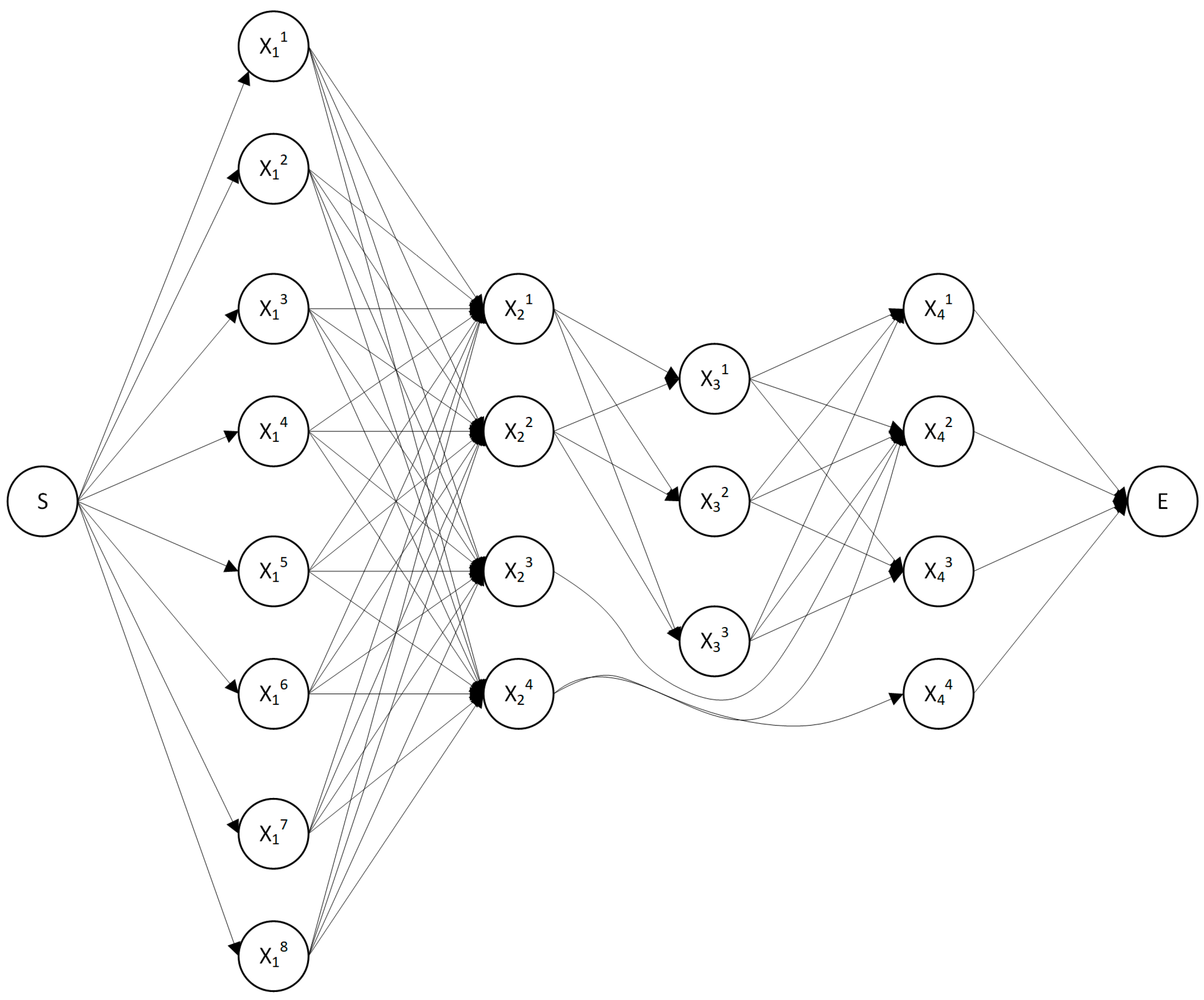
2.4. A Network Model of the Set of Possible Structural Variants
The set of possible structural variants
that fulfill the general function of the robot are represented in the form of a network model in
Figure 3. The vertices in the model are arranged in 4 columns according to the functions of the extractor. The possibilities of combining the devices
into structures
performing the general function of the drive system are shown by arrows. Each path connecting the beginning (S) and the end (E) of the network model represents a possible structural variant.
The network model shown in
Figure 3 describes the possible combinations of devices and their compatibility. In the developed variants, devices
and
are polyfunctional (can perform more than one function), performing functions F3 and F4.
3. Formulation and Analysis of the Problem of Choosing the Optimal Structural Variant
The choice of an optimal structural variant of a robot for extracting castings is related to solving the following problem:
When the functional structure of the robot is developed and the alternative devices for performing its functions are determined, a compatible combination of them must be determined that fulfills the overall function of the robot and satisfies pre-set requirements and conditions (restrictions) to the technical and economic characteristics of the extractor.
The analysis of the formulated problem reveals some of its characteristic features and problems that must be taken into account when formalizing it and choosing appropriate optimization methods.
The choice of a structural variant is carried out after a comprehensive (complex) evaluation of the competing variants according to a set of technical, economic, ergonomic, ecological, aesthetic, and other characteristics of the robot, which, depending on the specific requirements and goals of the problem being solved, must have optimal (minimum or maximum) values. Therefore, in the general case, the defined problem is a vector (multi-criteria, multi-objective) optimization problem. The solution of the problem belongs to a set of compromise solutions (set of non-optimizing solutions, set of efficient solutions, set of trade-offs), according to the principle of optimality proposed by Pareto [
23,
24,
25,
26].
The criteria for evaluating the variants are mainly determined by the list of requirements for the designed product [
22]. They can be both quantitative and qualitative.
Very often, the individual criteria are contradictory. For example, it is necessary to minimize the cost and payback period of capital investments while requiring maximum reliability, or the goal is to minimize energy costs and cost of the robot while requiring maximum performance.
In addition, the criteria have different physical meanings and are measured in different dimensions and scales—for example: productivity—pcs., technological cost—EUR/pc., compressed air consumption—l/h, area—m2, mass—kg, payback period of capital investments—years, price—EUR, installed power—kW, duration of work strokes—s, time for readjustment—min, etc. Therefore, it is necessary to perform normalization (norming) of the objective functions. Through normalization, they are converted into a dimensionless form and a uniform scale of measurement.
Solving multi-criteria optimization problems is related to a number of specific issues described in the specialized literature [
27,
28], which make their solution difficult:
choosing a way to normalize (norm) the criteria;
choosing an optimality principle;
determining the priority of the criteria;
choosing an appropriate optimization method, etc.
The large number of functions of the extractor robot and the large variety of alternative devices for their implementation predetermine the presence of a large number of possible structural variants that must be evaluated. Therefore, it is appropriate to use a method of directed search for the optimal solution and the development of application software that does not require the writing of additional programs and special knowledge from engineers.
The formulated problem belongs to the class of discrete programming problems. Finding a solution is accompanied by considerable difficulties. Solving the discrete problem by replacing it with a continuous analogue and subsequent rounding of the obtained solution to a close integer solution is impossible.
When solving the problem, it is necessary to take into account the presence of constraints on the compatibility between devices. Here, the term “compatibility” means the possibility of combining and simultaneously “operating” the devices in a common structure when performing the overall function of the system. Compatibility depends on a number of requirements and restrictions—geometric, informational, functional, etc. For example, when designing an industrial robot, it is not recommended to build it from modules and devices with different types of drive—electromechanical, pneumatic, hydraulic, etc., or from modules from different manufacturers. The simplest, but also the rarest, case is that in which there is compatibility between all elementary devices. In general, there is limited compatibility between devices.
An essential feature is also the possibility of a device performing more than one function. Typical examples of such polyfunctional devices are anthropomorphic industrial robots that have some modules for building manipulation systems that simultaneously perform translational and rotational movements, etc.
From the physical meaning of the problem, it is clear that individual criteria can have different “importance” (weight, significance) when choosing the optimal variant of the robot, i.e., one or more criteria to have priority over others. For example, ensuring the minimum technological cost and price of a robot are often more important criteria compared to the occupied area and the convenience of service.
When formalizing the problem, the possibility of constraints on the values of some technical and economic characteristics of the designed robot should be taken into account. For example, constraints can be placed on the size of the occupied area, the time to readjust, the price, the energy costs, etc. Therefore, in the general case, the problem has “resource” constraints, which can either have the functional type of “equality” and/or regional type “inequality”.
It is necessary to note that the choice of constraints must be made very carefully, because they define the region of permissible solutions of the problem. The introduction of redundant restrictions will narrow the permissible region, i.e., variants that are unreasonable to analyze will be reduced. Furthermore, the preparation time for solving the problem will also increase. On the other hand, not taking into account some constraints in order to reduce their number may lead to choosing of a variant that does not meet all the real requirements and permissible resources for the implementation of the system. This may require correction of the chosen solution at a later stage. Very often, this is associated with large additional costs.
4. Methodology for Choosing the Optimal Structural Variant
The selection of an optimal structural variant is carried out using a methodology that includes the following main stages:
Stage 1. Formulation of the problem.
Stage 2. Selection of optimization criterion (criteria).
Stage 3. Information provision.
Stage 4. Building a mathematical model.
Stage 5. Normalization of the criteria.
Stage 6. Determining the priority of the criteria.
Stage 7. Choice of optimality principle.
Stage 8. Selection of a mathematical method for solving the problem.
Stage 9. Development of algorithms and programs.
Stage 10. Solving the problem. Analysis of the obtained results.
The essence of the main stages will be briefly considered.
Stage 1. Formulation of the problem.
The formulation of the problem is one of the stages that requires the greatest responsibility in choosing an optimal structural variant, since its results are the basis for the subsequent solving of the problem.
The formulation of the problem includes:
specification of the requirements for the designed system;
specification of the objectives for the design object;
building a tree of objectives;
determination of constraints.
Stage 2. Selection of optimization criterion (criteria).
At this stage, the set of criteria for evaluating the alternative structural variants are determined depending on the specifics of the concrete problem. The set of criteria determine the properties of the designed robot to a significant extent. The criteria for choosing the optimal variant are mainly determined by the list of requirements for the design object and the defined goals. Each criterion represents an image: a “projection” of some objective. The selection of the system of criteria is carried out through conversations and consultations between the team of designers, the contracting authority, and/or other parties interested in the development (e.g., contractor, implementer, user, etc.).
Stage 3. Information provision.
At this stage, the values of the relevant technical and economic parameters and indicators are determined for all devices performing the functions of the robot. For the assessment of the alternative variants of the designed object according to the selected criteria and the verification of compliance with the imposed constraints, information provision is necessary. It will allow the determination of the values of the technical and economic characteristics of the object for which there are imposed constraints or an optimal value is sought. At the same time, it is necessary to ensure the unambiguity and credibility of the information to take measures to eliminate contradictions.
Stage 4. Building a mathematical model.
With selected criteria and constraints, an important stage in solving the problem of choosing an optimal structural variant is building the mathematical model.
For the considered problem of choosing an optimal structural variant of a robot, the mathematical model has the form:
Find a variant
,
,
that is optimal according to a set of criteria:
satisfying the constraints:
where
,
,
,
,
,
,
, where
is the vector of objective functions (vector optimization criterion);
—
k-th technical–economic characteristic of the robot, for which an optimal (maximum or minimum) value is sought,
;
—the
m-th technical-economic characteristic of the robot, on the value of which there is a constraint,
;
—the set of possible structural variants;
—the set of alternative devices performing the
n-th function;
—the
l-th device performing the
n-th function;
,
—discrete argument functions,
, that are tabulated.
Stage 5. Normalization of the criteria.
Most often, individual criteria are measured in different dimensions and scales. It is thus impossible to objectively compare the quality of alternative variants according to each criterion. In order to solve the problem at this stage, the criteria are translated into a single measure (measurement scale), and their scales are standardized.
After analyzing known ways of normalizing the objective functions, in the present work, it is proposed to use the so-called full normalization in one of the following ways, depending on the type of extremum:
For objective functions
to be maximized, one of the following functional transformations can be used:
where
is the current value of the objective function;
,
—respectively, the minimum and maximum (optimal) value of the
k-th objective function in the permissible domain;
—the set of objective function indices of the functions to be maximized.
As
, then
.
As , then .
As can be seen from (4) and (5), represents the relative evaluation of the satisfaction of the k-th criterion by the solution (relative attainment of the optimal value ), and —the relative deviation from the optimal value of the objective function for the solution .
- 2.
For objective functions to be minimized, one of the following functional transformations can be used:
where
,
are, respectively, the maximum and minimum (optimal) value of the
k-th objective function in the permissible domain;
—the set of objective function indices, of the functions to be minimized.
As
, then
.
As , then .
As can be seen from the dependencies (4)–(7), there is an unambiguous relationship between the relative estimate
and the relative deviation
:
Stage 6. Determining the priority of the criteria.
The selected criteria for evaluating the alternative variants may have different relative importance depending on the conditions of the specific problem and the requirements of the decision makers (DM). Determining the importance and value of the evaluations according to individual criteria must also take into account the meaning and content of the defined objectives for the designed system. In doing so, both objective and subjective (expert) information can be used. On the basis of analysis, the Saaty method [
29] is applied in the present work.
Stage 7. Choice of optimality principle.
In the problem under consideration, the principle of optimality (criterion for decision making) determines the properties of the optimal solution and gives an answer to the main question—in what sense does it surpass all other permissible solutions and determines the rule for its search. Various optimality principles have been proposed in a number of studies. The diversity of these principles reflects the different approaches to solving multi-criteria optimization problems.
In the specialized literature, there are no generally accepted recommendations for the use of one or another principle. The choice of an optimality principle depends on the conditions of the specific problem, the preferences of the designer and the client, and his ideas about the quality of the optimal solution, etc.
Taking into account the importance of the problem of choosing an optimal structural variant and taking into account the research and recommendations of a number of researchers, in the present work, it is proposed to use the principle of the guaranteed result (minimax or maximin).
Stage 8. Selection of a mathematical method for solving the problem.
The mathematical method for solving the problem reflects in principle the essence of the process of searching for the best solution and is a set of certain rules for an organized sequence of actions for this search.
It should be noted that there are no generally accepted criteria for evaluating the effectiveness of the methods in the specialized literature. For a successful choice, it is necessary to know the different optimization methods and their features, properties, and areas of application.
On the basis of an analysis of known methods, the present development proposes the use of two methods—the method of full combination and the method of consecutive analysis of variants. The first is used in problems with a smaller number of possible structural variants of the robot with up to 910 structural variants, and the second is based on a directed search for the optimal solution of problems with a dimension of up to 2020 variants.
Stage 9. Development of algorithms and programs.
At this stage, the algorithmic and software provisions of the problem are carried out. If possible, it is recommended to use already created and tested algorithms and programs.
To support the work of the designers, developed application software based on developed algorithms is used.
Stage 10. Solving the problem. Analysis of the obtained results.
At this stage, based on the input data and with the help of the constructed mathematical model and the chosen method, the problem is solved. An analysis of the obtained results follows. In the event that they do not satisfy the DM, iteration cycles are provided for re-solving the problem with a new priority of the optimality criteria and/or with another method. When these possibilities are exhausted, it is planned to return to the beginning of the algorithm and go through all the stages again.
Other iteration cycles and returning to different stages of the methodology are possible depending on the experience of the DM and the specifics of the concrete problem.
The proposed methodology has the following advantages:
Provides a systematic approach to the problem of choosing an optimal structural variant of a technical system;
Provides a mathematical model of the problem;
Proposes ways for criteria normalization;
Proposes an optimality criterion;
Generation of large number of possible variants in the initial stages of design;
Encourages functional thinking during the conceptual design stage;
Coming from the previous advantage is the benefit of modular design.
The proposed methodology has the following disadvantages:
A large amount of data have to be collected and analyzed in order to convert the evaluation criteria into objective functions;
Generating variants from combinations of devices that implement each function of the system requires the use of software supporting the solution of discrete optimization problems;
Additional complications can arise when including polyfunctional devices and compatibility between devices. These complications can be related to the ordering of the functions in the network model (
Figure 3), difficulties of using the network model as a tool for defining compatibility without a software support (in cases with very complicated relations between the devices), etc. For example, when the compatibility for every device has to be stated regarding all other devices, the network model becomes unpractical. In these cases, only compatibility matrices can be used as representation, and they are not convenient for use by people directly. Therefore, there is a high dependency on software support.
5. Dialog System for Computer-Aided Choosing of Optimal Structural Variant
In order to support the selection of an optimal structural variant of the extractor, the dialog system for multi-criteria optimization PolyOptimizer [
30] is used. It can solve discrete single-criteria and multi-criteria optimization problems in the presence of constraints, in the presence of incomplete compatibility between the components of the system, and also in the presence of polyfunctional components. The maximum number of objective and constraint functions is 10 each, and the maximum number of analyzed variants of the technical system is 20
20.
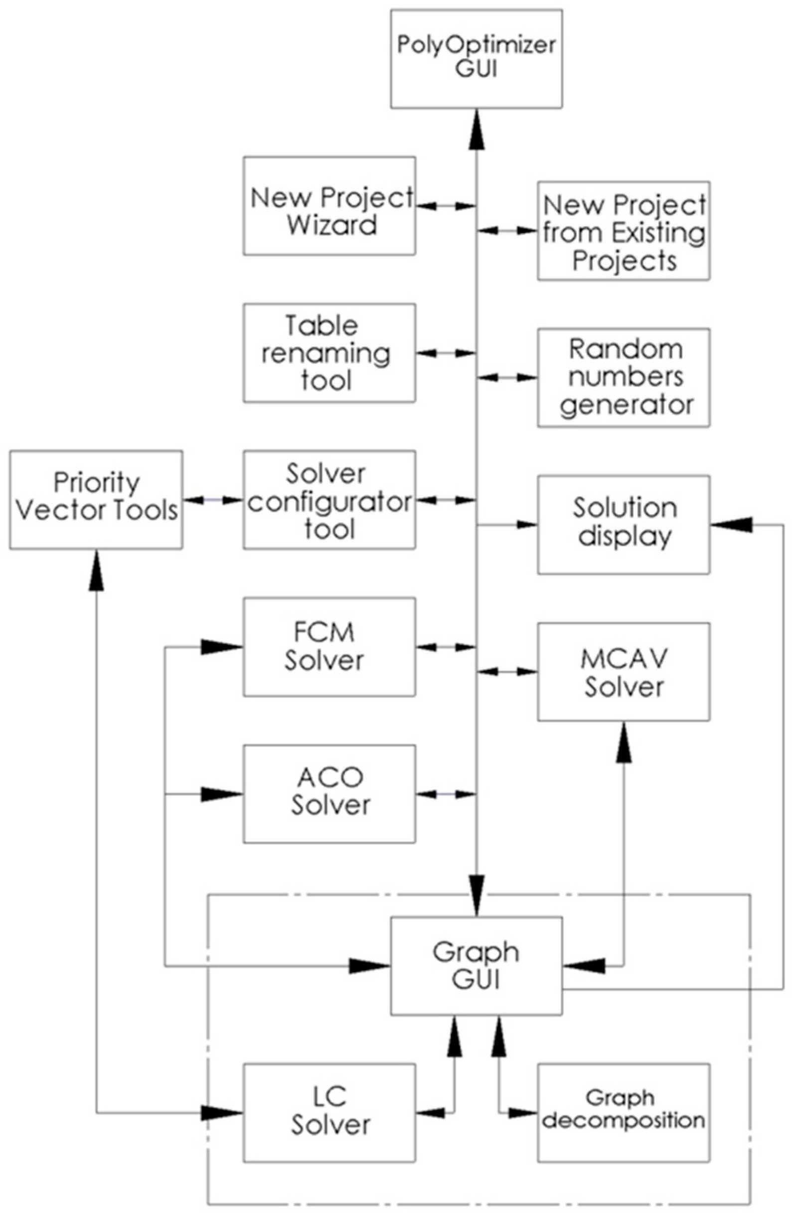
Figure 4 shows a block diagram of the modular architecture of PolyOptimizer. The modular architecture of the dialog system allows the easy addition of new modules implementing new algorithms. The graphical user interface of the dialog system is implemented using the object-oriented scripting language Python, and the modules requiring high performance and performing heavy mathematical calculations are implemented in ISO C [
31].
The main PolyOptimizer GUI module manages the graphical user interface (
Figure 5) and the synchronization between the other modules. It is designed according to the most common software products for working with tabular data, which ensures quick mastering of routine operations. In addition to its universal functions of a table editor, the software also provides specific functions related to the specialized tasks it solves.
The inputting of data into the tables of the objective and constraint functions is performed by an automated input procedure. Automatic error checking monitors the entered information and promptly reports a problem through standard dialog messages.
The PolyOptimizer dialog system offers the ability to create a database allowing the reuse of already entered tables, which helps to quickly reconfigure a given problem and explore different scenarios—for example, removing or adding variants in problems with an identical structure.
The possibility of naming and renaming the created tables through a unified interface supports the organization of the problem. In addition, naming the tables with user-intuitive names aids for quick orientation when re-using them.
In the current version of PolyOptimizer, three methods are available to solve the optimization problems—method of full combination (MFC)—FCM Solver module, method of consecutive analysis of variants (MCAV)—MCAV Solver module, and a method based on the ant colony algorithm (AC)—ACO Solver module.
MFC is used in problems with a smaller number of possible structural variants of the product. The algorithm is implemented to take advantage of multiprocessor systems—calculations are performed in parallel by the system’s processor cores, i.e., the process is multithreaded. An additional advantage is that dividing the load on the processor cores is not solely controlled by the operating system, but the software implementation of the algorithm itself divides the problem into separate parts, which are then solved by the corresponding number of cores. Despite the optimized code of the MFC program implementation, the maximum size of the problems that can be solved with it is 910 structural variants. With a larger number of structural variants, the time required to solve the problem becomes extremely large (combinatorial explosion).
Advanced MCAV algorithms are used to solve problems with a size greater than 910 variants. The method is characterized by a directed search for the optimal solution. At the same time, it allows reducing the set of solutions, thus allowing the application of MFC for problems with a very large size as well.
AC is a metaheuristic method for single- and multi-criteria optimization—ACO Solver module. This method makes it possible to find solutions to complex optimization problems in a reasonable time interval, but without guaranteeing that the solution found is optimal. Through this metaheuristic method, a solution to optimization problems can be found, which cannot be solved by other methods.
The Solver configurator tool module enables the configuration of the various parameters of the software implementations of MFC, MCAV, and AC. The user can determine by himself when and how to use the methods for searching of an optimal solution. No primary knowledge of the mathematical models or additional programming is required. The desired number of combinations to reduce the problem to before applying MFC can be controlled by the user. For multi-criteria optimization problems, the user can set solution search regions and different priorities for each objective function. For determining priority of the objective functions by a priority vector, different methods can be used. These are separated into a group of modules indicated in the modular architecture shown in
Figure 4 with the Priority Vector Tools module. When solving with MCAV, a text file is prepared with the detailed numerical solution of the problem, which can be viewed by the user with a text editing program for verification purposes.
Inputting data regarding the set of structural variants of the technical system is carried out through the Graph GUI module. Procedures are in place to ease this activity. Entering the information about compatibility between elementary devices and polyfunctionality, through the graphical interface, automatically builds the necessary mathematical models. The dialog system has the ability to decompose the set of possible structural variants into subsets containing only compatible devices.
The procedure for finding an optimal solution for problems with incomplete compatibility and/or the presence of multifunctional devices also provides the user with the opportunity to change the parameters of the algorithms used and to perform a complete analysis of the problem and the solutions found.
The dialog system allows graphical representation and comparison of the found solutions for a problem. This is convenient when analyzing the results and supports the making of a final decision.
6. Solving the Problem
The solution of the following problem is assigned:
Given a set of possible structural variants of the extractor, determine the optimal structural variant such that
where:
—production costs, EUR;
—energy costs, EUR/h;
—occupied space;
—service and repair time;
;
;
,
,
,
. The tabulated data for the objective functions are given in
Appendix A Table A1.
With the mathematical model constructed in this way, the value of the relevant objective function for a given possible structural variant of the system is defined as the sum of the technical and economic characteristics of the devices included in this structural variant.
Due to the presence of compatibility constraints, to apply the chosen optimization method, it is necessary to first decompose the set of structural variants of the extractor into subsets where there are no compatibility constraints. For this purpose, the PolyOptimizer optimization program environment is used. The set of possible structural variants of the extractor is decomposed into three subsets, the elements of which are shown in
Table 8.
The total number of possible structural variants of the designed system is 168. To determine the limits of variation (upper and lower boundary) of the objective functions, 24 single-criterion optimization problems are solved, and to find a solution to the multi-criteria problem, it is necessary to solve 3 multi-criteria optimization problems (one for each subset).
The considered problem is a multi-criteria optimization problem with polyfunctional devices and presence of compatibility constraints between the devices. It is solved using the PolyOptimizer dialogue system.
6.1. Solution under Equal Priority of the Objective Functions
The compromise solution of the problem is found for objective functions of equal importance.
Table 9 shows the values of the objective functions for the solution’s variant, as well as the devices included in the structure of the extractor.
Figure 6 shows the solution from PolyOptimizer.
Variant
(
Table 9) is composed of devices
(
Table 4, row 7),
(
Table 5, row 3), and
(
Table 7, row 2). At the end of the kinematic chain of an articulated mechanism (device
), two degrees of freedom are mounted—one rotational (device
) and one linear (device
). The pulling of the casting from the mold is carried out by device
. The movement to take the casting out of the overall dimensions of the machine plates and the positioning in the unloading position are carried out by device
. The orientation of the casting for unloading is performed by device
. The extractor is mounted to the die casting machine structure.
When analyzing the proposed solution, the following conclusions can be drawn:
The smallest deviation from its optimum has the energy consumption, and the largest is the production costs;
The compromise variant achieves small deviations from the optima of the objective functions;
The optimum is found in the second subset (
Table 8).
6.2. Solving for Different Criteria Priority
If the obtained solutions do not satisfy the DM, it can continue with the search for other solutions by changing the priority of the criteria. The investigation of the problem further continues with the introduction of different weighting coefficients.
Due to the larger deviation of production costs from the optimum for the objective function, one promising research direction is precisely to set a higher priority for this objective function. Other directions in which a change of the obtained results can be sought is the occupied space and the service and repair time.
For the reasons described above, the DM initially decides to investigate the problem with a higher priority for production costs. Therefore, the following problem is set:
Determine a weight vector that assigns a higher priority to the production cost criterion of the extractor.
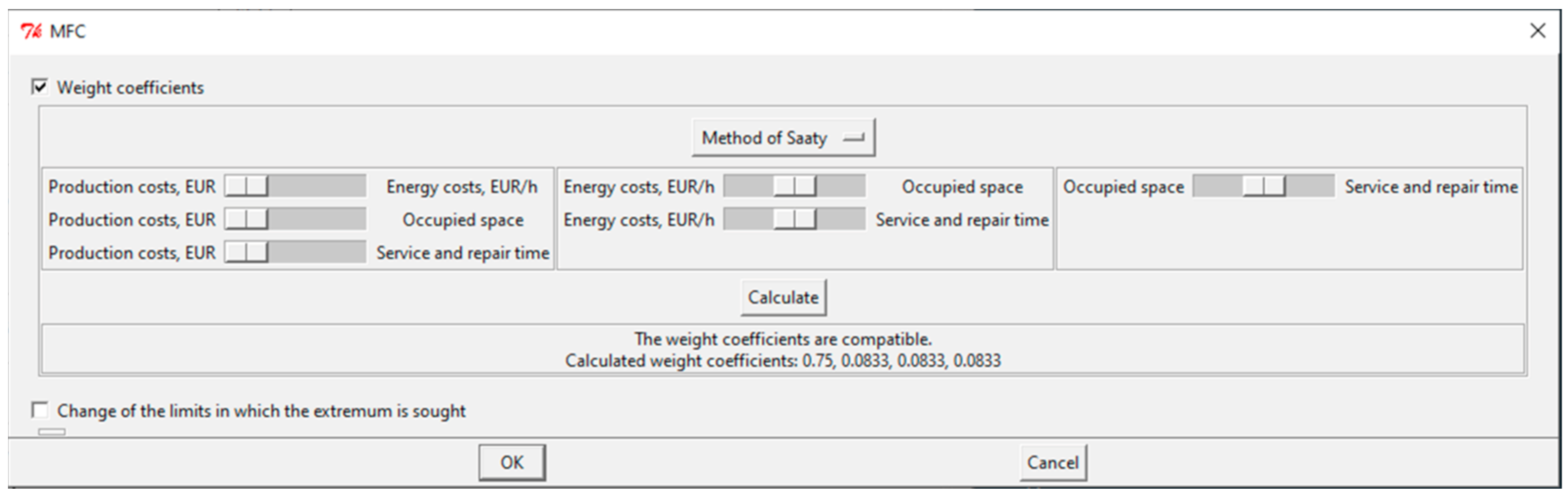
Through Saaty’s method, the production costs are prioritized.
Figure 7 shows the user interface of the method in the PolyOptimizer dialog system, through which the parameter values are entered. There are six binary comparisons for the particular problem. Production costs are prioritized over energy costs, occupied space, and service and repair time. DM has set these parameters through the sliders (
Figure 7). The figure shows that equal importance is set for the remaining criteria by placing the sliders midway between the comparison pairs. After calculating the weighting coefficients, the problem can be solved with the entered information regarding the priority of the criteria.
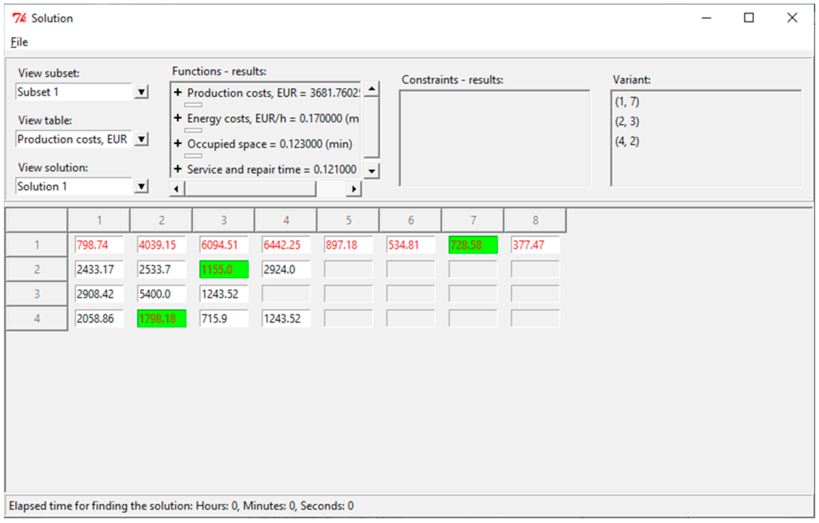
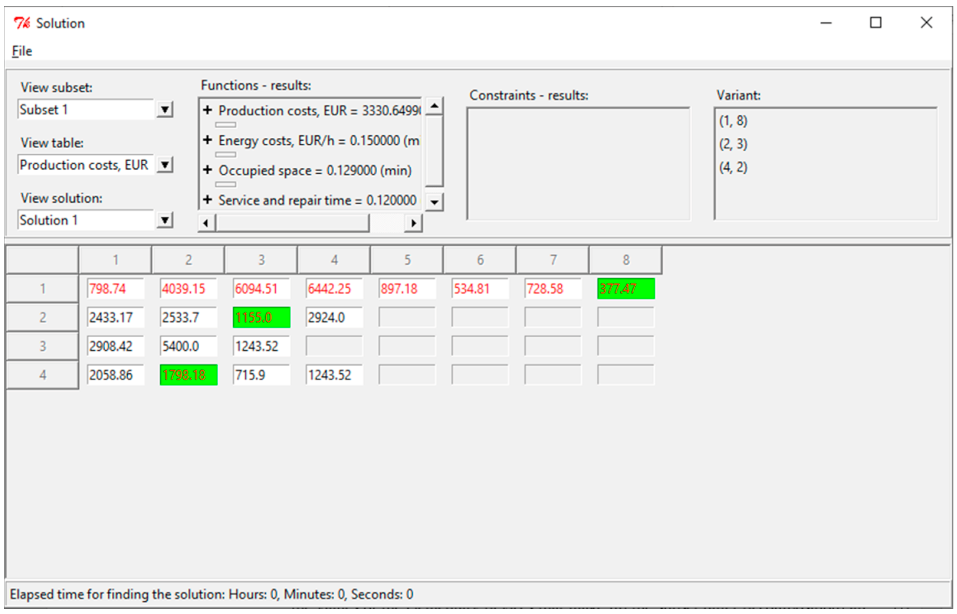
Figure 8 shows the found solution rendered through the graphical user interface of the dialog system. The calculated priority vector is
.
In
Figure 8, the devices that make up the structural variant are marked in green, and the values of the elementary devices that make up the subset (after decomposition) are written in red. The values obtained for this solution are summarized in
Table 10.
The differences between this structural variant and variants are in one device—performing the function of extracting the casting from the mold. Manufacturing and energy costs are improved by 3% and 2%, respectively, over solution . Service and repair time is improved by 1%. On the other hand, the occupied space deteriorates by 4%.
If the proposed variant satisfies the DM, then it is selected for the solution of the problem. Otherwise, a new priority is set. The energy consumption already reaches its optimum for solution
; therefore, with the help of the PolyOptimizer dialog system, the situation where a higher priority is given to the occupied space is investigated. In
Figure 9 is shown the user interface for setting higher priority for the occupied space. The calculated priority vector is
.
When setting a priority by Saaty’s method, a solution
(
Table 11) is obtained, which also differs from
by only one device. This results in a reduction of the occupied space by 2%. Service and repair time is also improved by 2%. Manufacturing costs and energy costs worsened by 1% and 13%, respectively.
The problem is solved also with priority for service and repair time. The solution coincides with solution
(
Table 10).
6.3. Solving When Considering Floor-Mounted Variants Only
The solutions obtained in
Section 6.2 are solutions including only one type of construction of the robot extractor—with mounting to the supporting structure of the die casting machine. In the set of possible variants (
Figure 3), there are also floor-mounted structures, attached close to the casting machine, but not to its structure. The following solution is obtained by modifying the set of possible variants so that only floor-mounted structures are present. In practice, this is accomplished by removing device
from the set of possible structural variants. Thus, subset 2 (
Table 8) is dropped. The solution found for equal objective functions is shown in
Table 12. The upper and lower boundaries of the objective functions and the corresponding deviations from the optimum have been equated to those of the previous problems for the purpose of a more convenient comparison.
Variant
(
Table 12) is an articulated mechanism driven by an electric motor. At the end of the kinematic chain of the articulated mechanism, two degrees of freedom are installed—one rotational and one linear. The devices are the same as for variant
. The difference here is the articulated mechanism, which performs movement in a vertical plane; another difference is that the extractor is mounted to the floor of the room near the casting machine. The achieved deviations from the optimums of the objective functions are greater than the compromise variant
.
6.4. Solution When Examining the Subsets
Subsets 1 and 3 are additionally investigated, and the compromise solutions for them are found. This is performed because all previous solutions found are part of subset 2 and further investigation of the other subsets is of interest to find alternative solutions. Accordingly,
Table 13 and
Table 14 show the compromise solutions for these subsets.
Variant
(
Table 13) is a telescopic arm driven by an electric motor and performing linear movement by converting rotation into translation with a chain gear. The extracting of the casting is performed by the same device as in variant
, and the orientation of the casting for unloading is performed by a rotary pneumatic unit. The positioning of the robot in the position for unloading the casting is performed by an articulated mechanism driven by a pneumatic cylinder. The articulated mechanism is the first link of the kinematic chain of the extractor and is mounted on the floor of the room.
Variant
(
Table 14) is an articulated mechanism with electric drive, which is a multifunctional device and performs partial functions 2 and 3. The mechanism is the first link in the kinematic chain of the extractor and is mounted on the floor of the room. The extraction of the casting is performed by an articulated mechanism driven by an electric motor and a screw drive to convert rotation into translation. The orientation of the casting for unloading is performed by an articulated mechanism driven by a pneumatic cylinder.
Both variants that were found differ significantly in construction from solution
. In addition, the achieved deviations from the optimums of the objective functions are significantly larger than the compromise variant
. In
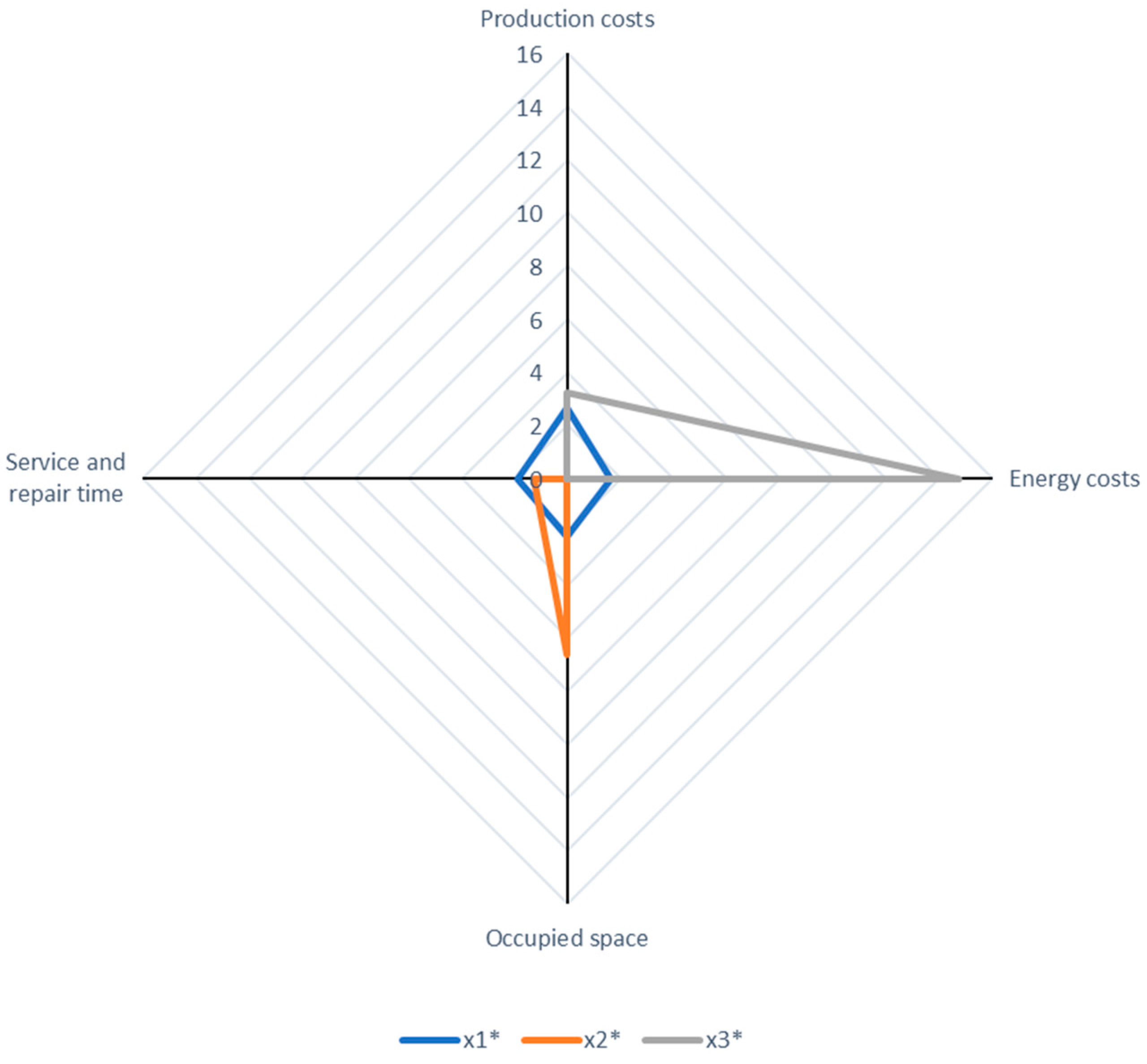
Figure 10 and
Figure 11, the six solutions found are summarized. Graphical representation is made through a radar diagram on which each axis represents an evaluation criterion. The different colored rectangles plotted on the diagrams are the six solutions. The values on the axes are the percentage deviations of the solutions found for each criterion. The ideal solution that simultaneously achieves an optimum by all criteria is the point of intersection of the axes in the center of the diagram. The graph can be likened to a target—the more concentrated the variant’s rectangle is around the zero point, the closer it is to the ideal solution.
For a better understanding of the results, the six solutions are presented in two separate figures—in
Figure 10, variants
,
, and
are shown, and in
Figure 11, variants
,
, and
are shown.
From
Figure 10, it can be seen that the compromise solution
is the most concentrated, as solutions
and
are also close to ideal, except for the “horns” obtained due to the prioritization of one or another objective function and the corresponding “allowance” to the detriment of the others.
From
Figure 10 and
Figure 11, one can see the tendency to balance the compromise solutions
,
,
, and
, where no clearly pronounced “horns” are noticeable.
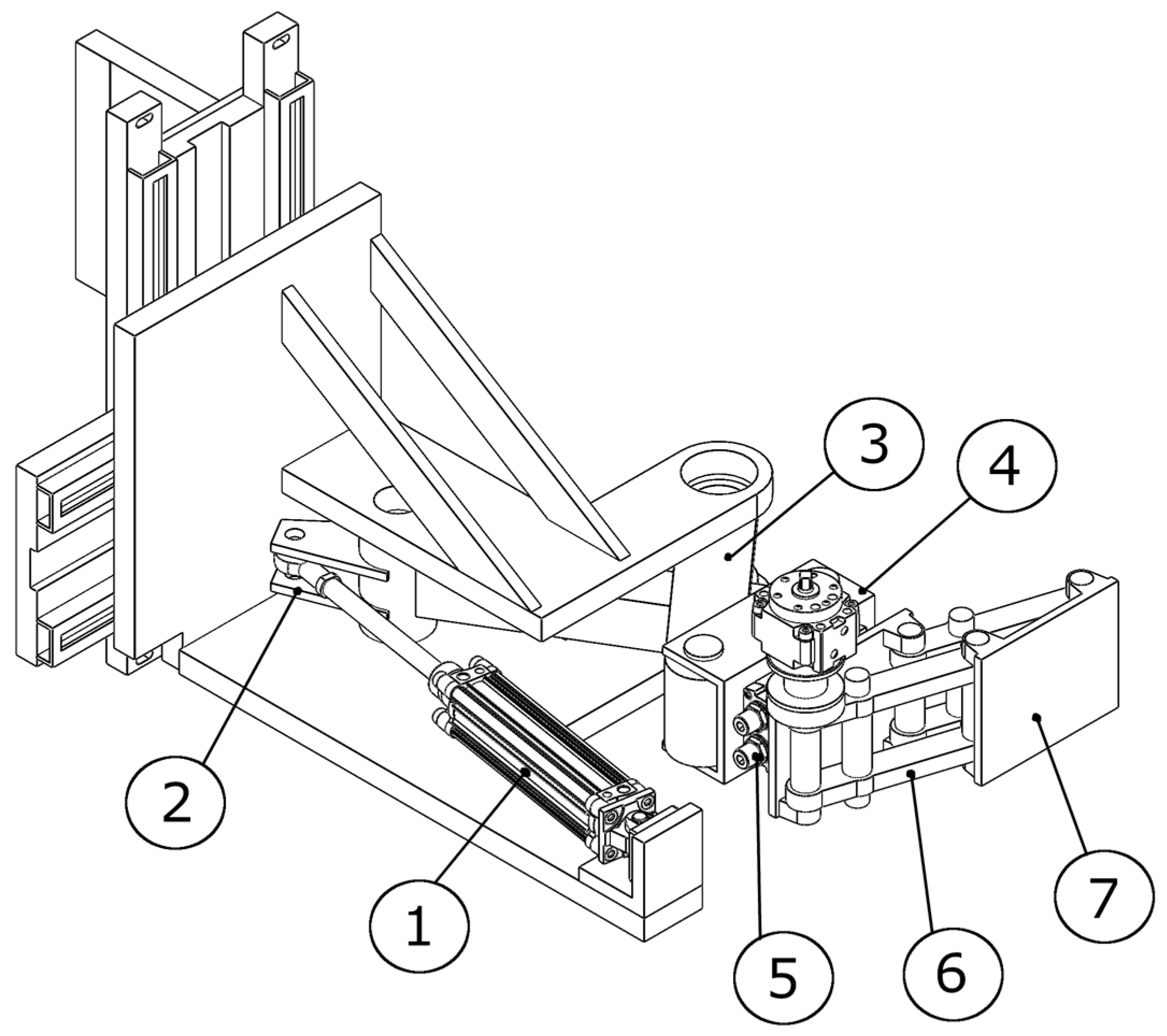
On the basis of the found solutions and their graphical analysis, a decision was made by the DM to pass variant
(
Figure 12) for further development, since it achieves close to optimal results for all objective functions and is well balanced. The kinematic diagram of the solution is given in
Figure 13.
The chosen solution variant is composed of three axes of movement. All three are pneumatically driven. The trajectory of movement for all axes is fixed. All three axes are controlled end to end, performing the move until end of stroke is reached. Therefore, the movement trajectory of the robot is fixed as is typical for a specialized robot. No intermittent positioning is possible with this variant. Further modeling and study of the motion law of the robot require mathematical modeling of the pneumatic motors and mechanical system. An approach for such modeling based on one DOF is proposed in [
32].
It should be noted that no gripper is attached to the shown configuration as the gripper design is not included in the current research and is typically configured with regard to a particular gripping task. The gripper must be attached to the end of arm component (7).
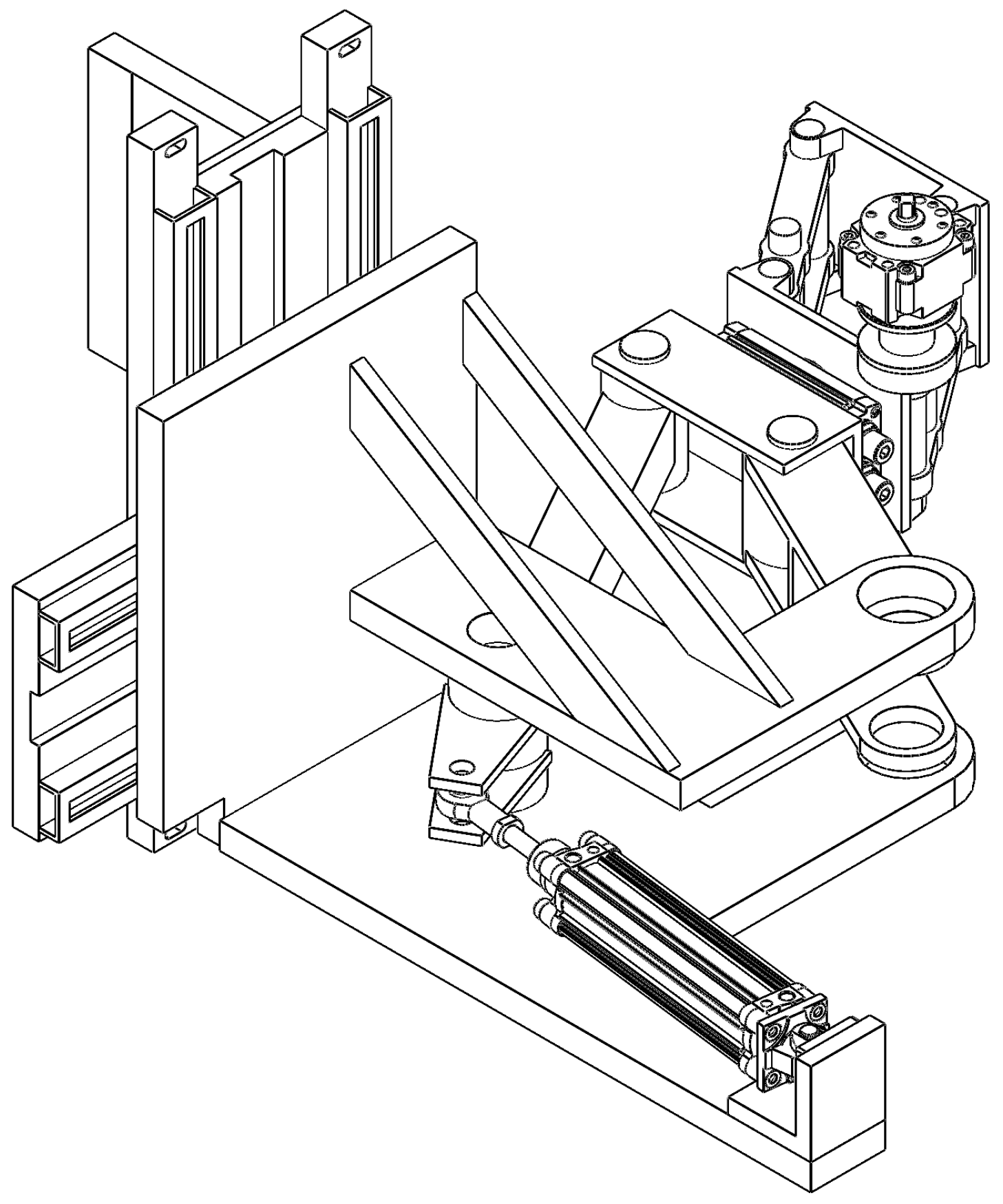
The cycle of the robot is as follows: the initial pose (starting position for the cycle) of the robot is as shown in
Figure 12. When the mold is opened, the pneumatic cylinder (1) (
Figure 12 and
Figure 13) is actuated, retracting its piston rod, and setting in motion the articulated mechanism composed of (2), (3), and (4). The link (4) is rotated 90 degrees, which also changes the orientations of the devices attached to it. Now, the robot has reached between the casting machine plates and is in position for extracting the casting (
Figure 14). In this position, the linkage mechanism composed of (6) and (7) is actuated by a rotary pneumatic motor, and the plate (7) moves forward, bringing the gripper into position for gripping the casting (
Figure 15). After the gripper has securely gripped the casting, the plate (7) is retracted to its initial position shown in
Figure 14. The extracting motion is synchronized with the mold’s ejectors. After the extraction, the pneumatic cylinder (1) is actuated for a forward stroke, which returns the robot to the position depicted in
Figure 12. In this position, the casting is unloaded. The rotary actuator (5) allows for changing the orientation of the casting before unloading, if necessary. After unloading the casting, the cycle is repeated.
7. Conclusions
In the present work, the problem of choosing of an optimal structural variant of a robot for extracting castings from die casting machines is solved. For this purpose, the process of extracting castings from die casting machines is analyzed. The result of the analysis is a developed functional model of a robot for extracting castings. The model includes the definition of a general function, inputs, outputs, and a functional structure. Additionally, market research on the offered die casting machines and robot extractors is made, which results in determining the specifications for the designed extractor. For each function of the functional structure implementation, variants are developed. The variants are organized in tables including a graphical representation, written description, and a kinematic diagram. The result is a set of possible variants and a directed graph of possible combinations. The latter is a graphical representation of multifunctional devices and compatibility between devices. A setting and analysis of the problem of choosing the optimal structural variant is carried out. A significant amount of information is collected for the evaluation criteria to be converted from a verbal/textual representation into objective functions (mathematical representation), with the purpose of formalizing the problem. As a result, a mathematical model of the problem is built. All modeling information is entered into a dialog system for multi-criteria optimization, which helps to facilitate analysis and finding solutions. The set problem of choosing the optimal structural variant of an extractor is solved under different decision making conditions, and the solutions found are presented and analyzed. The result of the analysis is the choice of a variant, which is selected to continue in the next phase of development. A comprehensive description of the chosen variant is given, both of its structure and working process.
Through this work, the following more important results are obtained:
A concept design of a specialized robot extractor, applying a systematic design approach;
A large number (168) of possible structural variants of the robot extractor are developed and evaluated;
The objective functions used for evaluating the developed structural variants are not only based on technical criteria, but also on criteria that are related to economic factors and to the actual exploitation of the equipment;
Problem analysis using specialized software tools that do not require prior knowledge of the mathematical models used.
In addition, the present development is also an illustrative and comprehensive example that can be generalized to practically any type of technical system. The only requirement is the use of a systematic approach to design and functional thinking (functional representation of the structure of the product being developed).
The formulation and analysis of the problem for choosing an optimal structural variant gives the basic guidelines for developing and choosing necessary tools for finding a solution.
The obtained results are going to be used in a future development; that is, the construction of a size range that integrates the solution chosen in the present work as the basic size. The basic size of a size range predetermines the general structure of all sizes, and therefore, the choosing of an optimal variant is crucial for the success of the range. This will also require the development of tools that will support the process of solving the problem and will expand the capabilities of the dialog system used.


