
Finite-Time Control for Dual Three-Phase Hybrid Excitation Synchronous Machine Based on Torque Sensorless Current Coordinative Strategy
Abstract
:1. Introduction
- GPIO is designed to estimate the load torque online, avoiding the use of a traditional hardware sensor. This approach not only increases the fault tolerance but also reduces the cost and complexity of the DTP-HESM system.
- The speed regulation based on NTSMC+GPIO is proposed in the whole speed region, which improves the rapidity, accuracy and robustness to multiple disturbances.
- The general idea can also be applied for other CCSs of HESM, such as the minimum copper consumption distribution and the optimal efficiency distribution, etc.
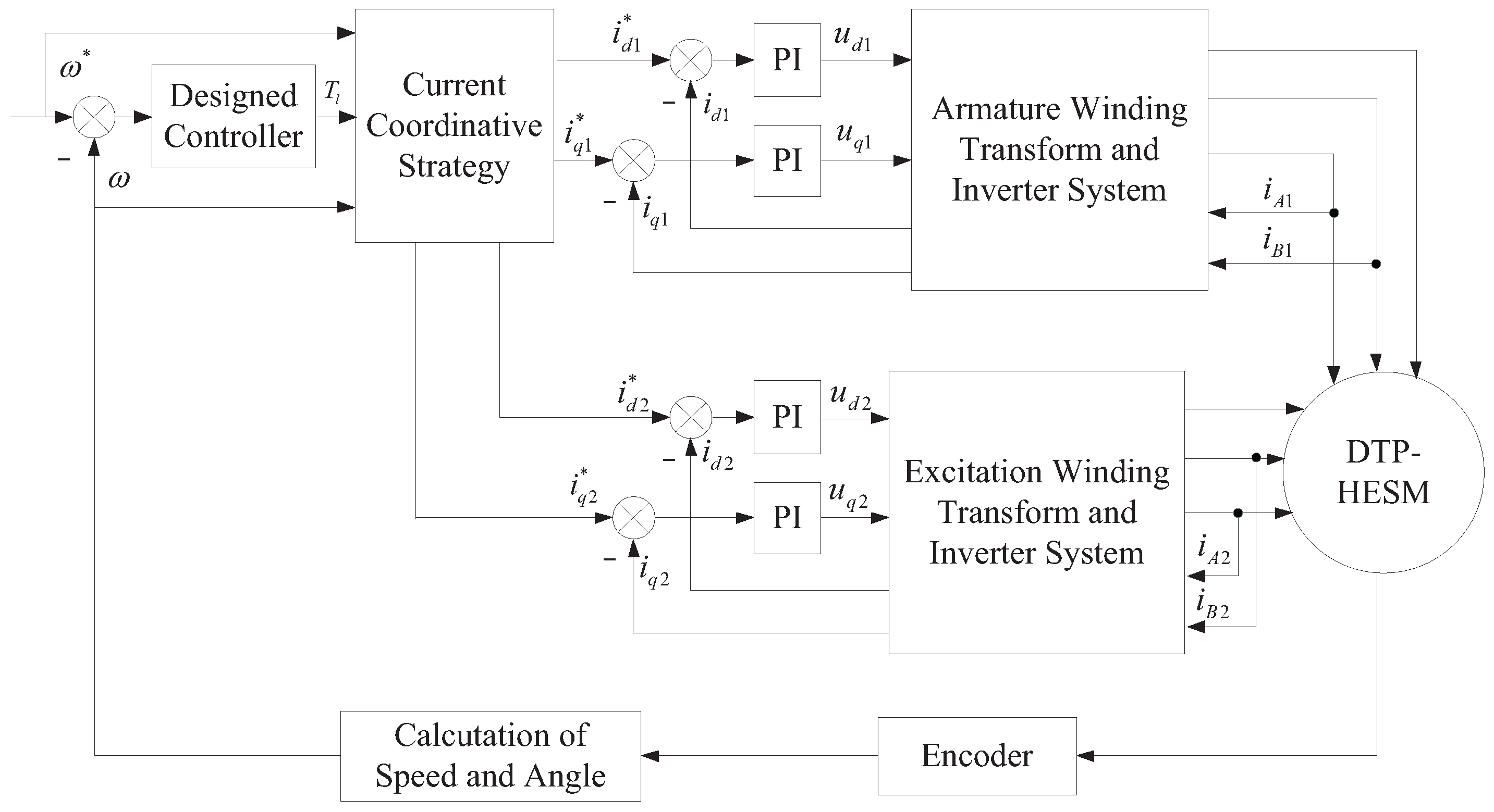
2. Dynamic Model and Current Coordinative Strategy
2.1. Mathematical Model
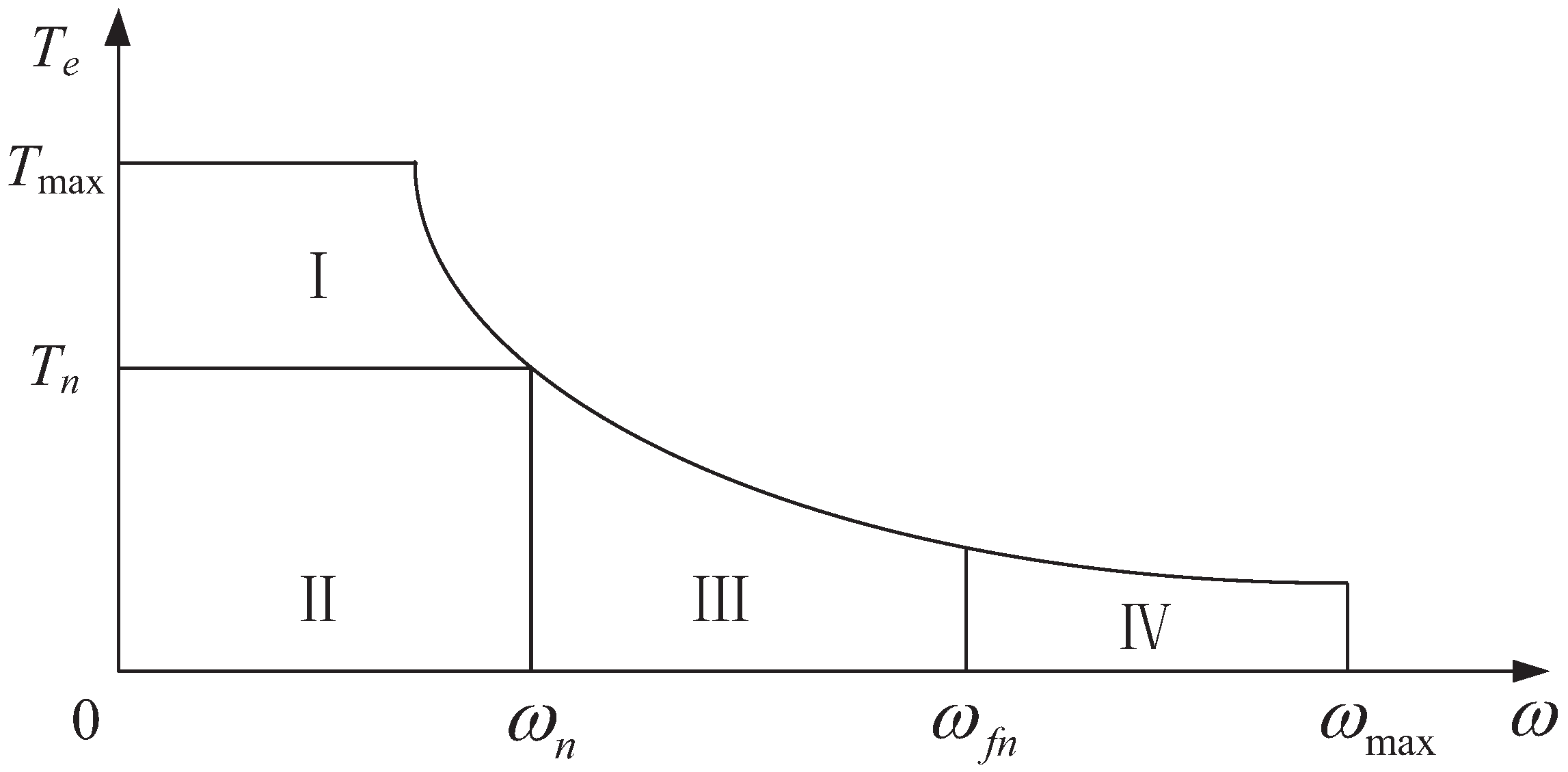
2.2. Current Coordinative Strategy
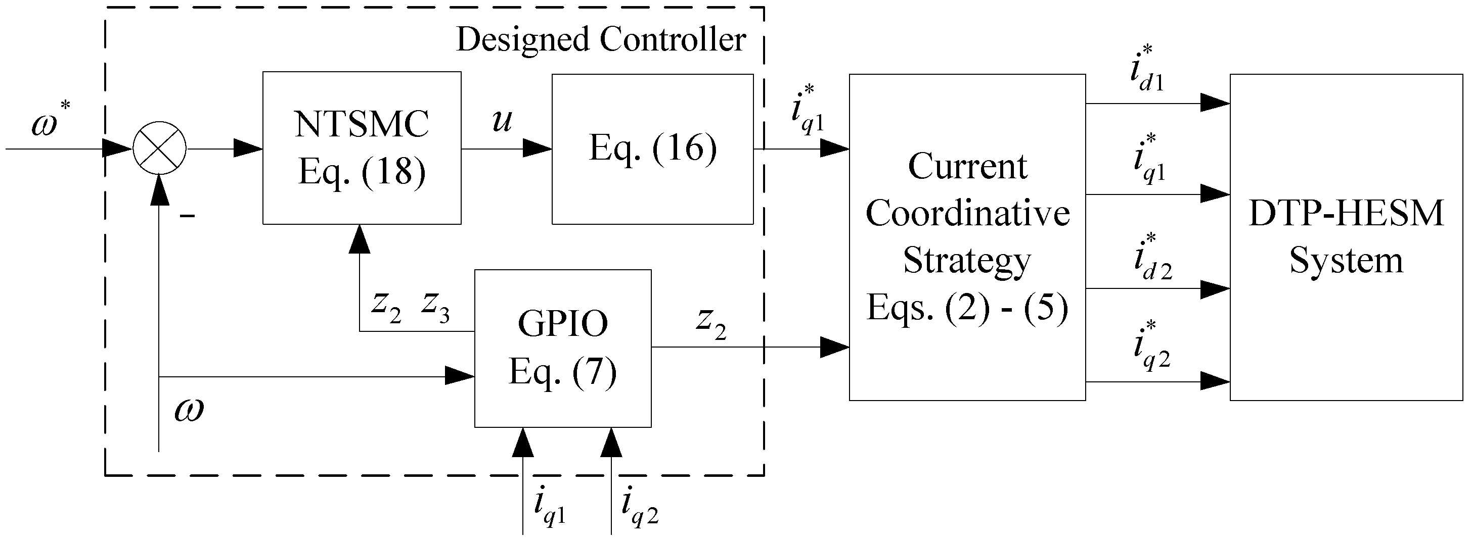
3. Controller Design
3.1. Design of GPIO
3.2. Design of the Composite Controller
3.3. Stability Analysis
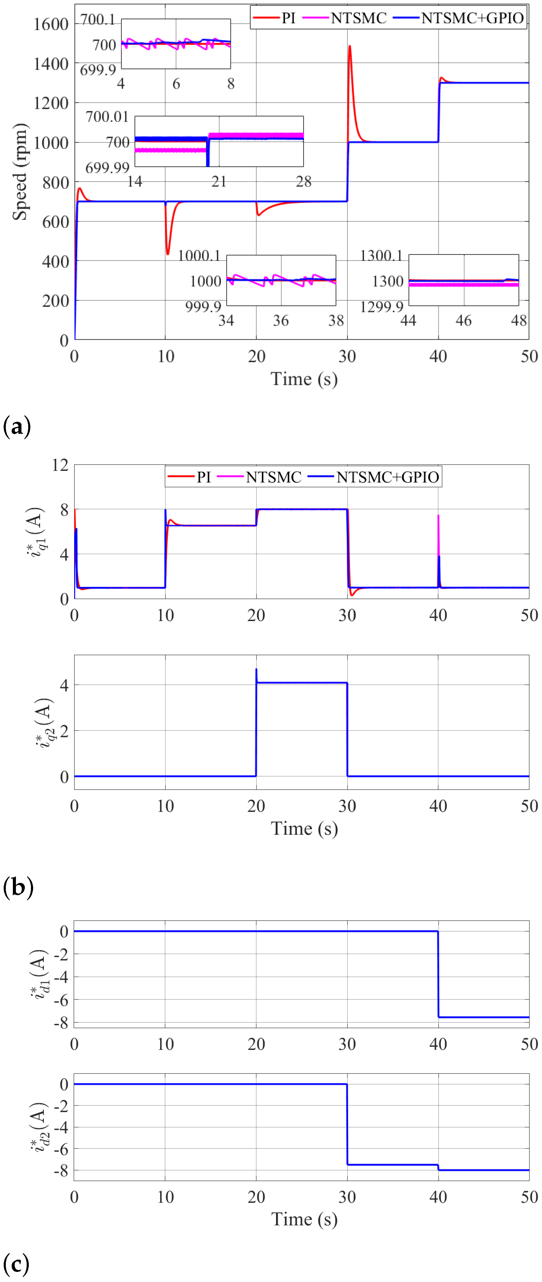
4. Number Tests Results
5. Experiment Results and Discussion
5.1. Results in the LSR
5.2. Results in the HSR
6. Conclusions
Author Contributions
Funding
Institutional Review Board Statement
Informed Consent Statement
Data Availability Statement
Conflicts of Interest
References
- Yao, G.; Yang, Y.; Wang, Z.; Xiao, Y. Permanent magnet synchronous motor control based on phase current reconstruction. Electronics 2023, 12, 1624. [Google Scholar] [CrossRef]
- Roshandel, E.; Mahmoudi, A.; Kahourzade, S.; Soong, W. Efficiency maps of electrical machines: A tutorial review. IEEE Trans. Ind. Appl. 2023, 59, 1263–1272. [Google Scholar] [CrossRef]
- Zhu, Z.; Cai, S. Hybrid excited permanent magnet machines for electric and hybrid electric vehicles. CES Trans. Electr. Mach. Syst. 2019, 64, 233–247. [Google Scholar] [CrossRef]
- Dong, T.; Gao, Y.; Nakamura, T. High fault-tolerance dual-rotor synchronous machine with hybrid excitation field generated by halbach permanent magnets and high temperature superconducting magnets. IEEE Trans. Appl. Supercond. 2023, 33, 5202105. [Google Scholar] [CrossRef]
- Wang, Q.; Niu, S. Overview of flux-controllable machines: Electrically excited machines, hybrid excited machines and memory machines. Renew. Sustain. Energy Rev. 2017, 68, 475–491. [Google Scholar] [CrossRef]
- Wang, X.; Wang, Z.; Xu, Z. A hybrid direct torque control scheme for dual three-phase PMSM drives with improved operation performance. IEEE Trans. Power Electron. 2019, 34, 1622–1634. [Google Scholar] [CrossRef]
- Liu, T.; Zhu, Z.; Wu, Z.; Stone, D.; Foster, M. A simple sensorless position error correction method for dual three-phase permanent magnet synchronous machines. IEEE Trans. Energy Convers. 2021, 36, 895–906. [Google Scholar] [CrossRef]
- Karttunen, J.; Kallio, S.; Peltoniemi, P.; Silventoinen, P.; Pyrhonen, O. Dual three-phase permanent magnet synchronous machine supplied by two independent voltage source inverters. In Proceedings of the International Symposium on Power Electronics Power Electronics, Electrical Drives, Automation and Motion, Sorrento, Italy, 20–22 June 2012; pp. 741–747. [Google Scholar]
- Hu, Y.; Zhu, Z.; Odavic, M. Comparison of two-individual current control and vector space decomposition control for dual three-phase PMSM. IEEE Trans. Ind. Appl. 2017, 53, 4483–4492. [Google Scholar] [CrossRef]
- Chen, H.; El-Refaie, A.; Demerdash, N. Flux-switching permanent magnet machines: A review of opportunities and challenges-part II: Design aspects, control and emerging trends. IEEE Trans. Energy Convers. 2020, 35, 699–713. [Google Scholar] [CrossRef]
- Lu, X.; Fan, Y.; Chen, J.; Lei, Y. Flux control of consequent-pole hybrid excitation motors in constant power region to achieve both high efficiency and fast convergence speed. J. Power Electron. 2022, 2, 10–21. [Google Scholar] [CrossRef]
- Zhang, Z.; Liu, Y.; Tian, B.; Wang, W. Investigation and implementation of a new hybrid excitation synchronous machine drive system. IET Electr. Power Appl. 2017, 11, 487–494. [Google Scholar] [CrossRef]
- Zhao, J.; Lin, M.; Xu, D. Minimum-copper-loss control of hybrid excited axial field flux-switching machine. IET Electr. Power Appl. 2016, 10, 82–90. [Google Scholar] [CrossRef]
- Liu, Y.; Zhang, Z.; Wang, C.; Gao, H. Optimization and performance improvement of a hybrid excitation synchronous machine with modular magnetic-shunting rotor. IEEE Trans. Ind. Electron. 2020, 67, 4381–4390. [Google Scholar] [CrossRef]
- Druant, J.; Vansompel, H.; Belie, F.; Sergeant, P. Optimal control for a hybrid excited dual mechanical port electric machine. IEEE Trans. Energy Convers. 2017, 32, 599–607. [Google Scholar] [CrossRef]
- Pothi, N.; Zhu, Z.; Ren, Y. Comparison of flux-weakening control strategies of novel hybrid-excited doubly salient synchronous machines. IEEE Trans. Ind. Appl. 2017, 55, 3589–3597. [Google Scholar] [CrossRef]
- Huang, M.; Zhang, Y.; Huang, Q.; Guo, X.; Qing, Y. Hybrid excitation synchronous machine adaptive speed region control and experimental verification. Int. J. Appl. Electromagn. Mech. 2018, 58, 275–287. [Google Scholar] [CrossRef]
- Ding, W.; Li, S. Maximum ratio of torque to copper loss control for hybrid excited flux-switching machine in whole speed range. IEEE Trans. Ind. Electron. 2019, 66, 932–943. [Google Scholar] [CrossRef]
- Pothi, N.; Zhu, Z. Control strategy for hybrid-excited switched-flux permanent magnet machines. IET Electr. Power Appl. 2015, 9, 612–619. [Google Scholar] [CrossRef]
- Geng, Y.; Han, P.; Chen, X.; Chen, R.; Le, Z.; Lai, Z. Online dead-time compensation method for dual three phase PMSM based on adaptive notch filter. IET Power Electron. 2021, 14, 2452–2465. [Google Scholar] [CrossRef]
- Xu, Y.; Zheng, B.; Wang, G.; Yan, H.; Zou, J. Current harmonic suppression in dual three-phase permanent magnet synchronous machine with extended state observer. IEEE Trans. Power Electron. 2020, 35, 12166–12180. [Google Scholar] [CrossRef]
- Karttunen, J.; Kallio, S.; Peltoniemi, P.; Silventoinen, P. Current harmonic compensation in dual three-phase PMSMs using a disturbance observer. IEEE Trans. Ind. Electron. 2016, 63, 583–594. [Google Scholar] [CrossRef]
- Hou, Q.; Zuo, Y.; Sun, J.; Lee, C.; Wang, Y.; Ding, S. Modified nonlinear active disturbance rejection control for PMSM speed regulation with frequency domain analysis. IEEE Trans. Power Electron. 2023, 38, 8126–8134. [Google Scholar] [CrossRef]
- Hou, Q.; Ding, S.; Yu, X. Composite super-twisting sliding mode control design for PMSM speed regulation problem based on a novel disturbance observer. IEEE Trans. Energy Convers. 2021, 36, 2591–2599. [Google Scholar] [CrossRef]
- Wu, L.; Liu, J.; Varquez, S.; Mazumder, S. Sliding mode control in power converters and drives: A review. IEEE CAA J. Autom. Sin. 2022, 9, 392–406. [Google Scholar] [CrossRef]
- Fnaiech, M.; Betin, F.; Fnaiech, F.; Capolino, G. Sliding mode control for dual three-phase induction motor drives. In Proceedings of the International Symposium on Power Electronics Power Electronics, Electrical Drives, Automation and Motion, Montreal, QC, Canada, 9–13 July 2006; pp. 2281–2285. [Google Scholar]
- Lu, E.; Li, W.; Yang, X.; Liu, Y. Anti-disturbance speed control of low-speed high-torque PMSM based on second-order non-singular terminal sliding mode load observer. ISA Trans. 2019, 88, 142–152. [Google Scholar] [CrossRef] [PubMed]
- Li, S.; Zhou, M.; Yu, X. Design and implementation of terminal sliding mode control method for PMSM speed regulation system. IEEE Trans. Ind. Inform. 2013, 9, 1879–1891. [Google Scholar] [CrossRef]
- Bai, C.; Yin, Z.; Luo, J.; Luo, P.; Liu, J. Robust composite finite-time convergent speed control of induction machine based on multiple sources disturbance estimation technology generalized proportional integral observer. IEEE/ASME Trans. Mechatron. 2022, 10, 6160–6170. [Google Scholar] [CrossRef]
- Yang, J.; Li, S.; Yu, X. Sliding-mode control for systems with mismatched uncertainties via a disturbance observer. IEEE Trans. Ind. Electron. 2013, 60, 160–169. [Google Scholar] [CrossRef]


| Symbol | Value | Symbol | Value |
|---|---|---|---|
| 10 | |||
| J | |||
| B |
| Test Type | Performance Index | PI | NTSMC | NTSMC+GPIO |
|---|---|---|---|---|
| startup | OS [rpm] | 68.53 | 0.02 | 0.01 |
| ST [s] | 0.28 | 0.27 | 0.3 | |
| First step load torque | SD [rpm] | 270 | 21 | 22 |
| RT [s] | 3.3 | 0.2 | 0.2 | |
| Second step load torque | SD [rpm] | 72 | 3 | 3 |
| RT [s] | 8.2 | 0.1 | 0.1 | |
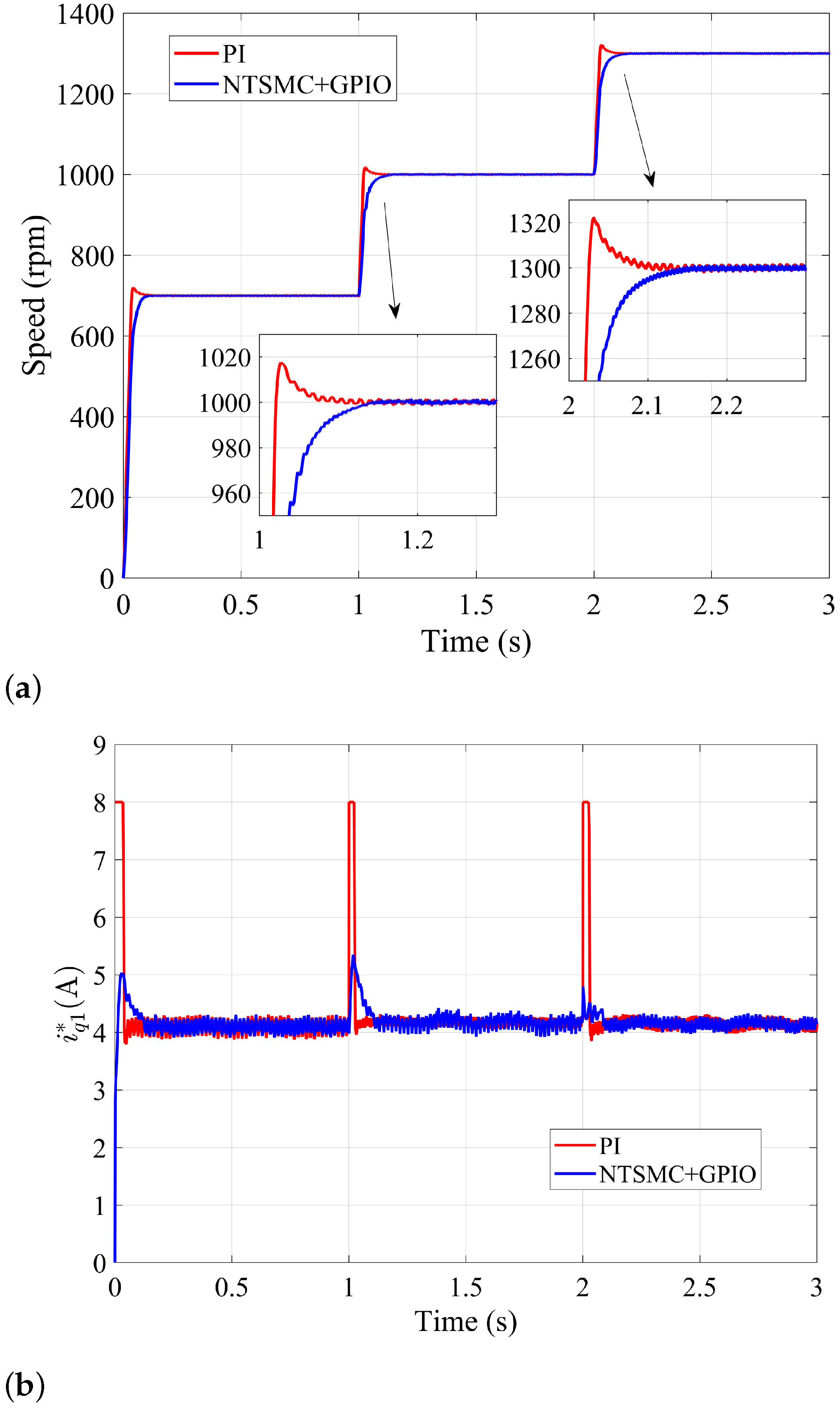
| First step speed-up | OS [rpm] | 489.7 | 0.02 | 0.01 |
| ST [s] | 1.5 | 0.1 | 0.1 | |
| Second step speed-up | OS [rpm] | 27.5 | 0.02 | 0.01 |
| ST [s] | 1.1 | 0.05 | 0.1 |
| Test Type | Performance Index | PI | NTSMC+GPIO |
|---|---|---|---|
| startup | OS [rpm] | 20.31 | 0.59 |
| ST [s] | 0.050 | 0.086 | |
| RMSE [rpm] | 1.01 | 0.99 | |
| 1st step load torque | SD [rpm] | 30.13 | 9.56 |
| RT [s] | 0.069 | 0.072 | |
| RMSE [rpm] | 0.82 | 0.83 | |
| 2st step load torque | SD [rpm] | 10.54 | 7.29 |
| RT [s] | 0.105 | 0.106 | |
| RMSE [rpm] | 0.96 | 0.99 |
| Test Type | Performance Index | PI | NTSMC+GPIO |
|---|---|---|---|
| 1st step speed-up | Overshoot [rpm] | 17.65 | 0.41 |
| Setting time [s] | 0.019 | 0.061 | |
| Root-mean-square error [rpm] | 0.92 | 0.95 | |
| 2st step speed-up | Overshoot [rpm] | 21.05 | 0.67 |
| Settling time [s] | 0.022 | 0.052 | |
| Root-mean-square error [rpm] | 1.06 | 1.08 |
Disclaimer/Publisher’s Note: The statements, opinions and data contained in all publications are solely those of the individual author(s) and contributor(s) and not of MDPI and/or the editor(s). MDPI and/or the editor(s) disclaim responsibility for any injury to people or property resulting from any ideas, methods, instructions or products referred to in the content. |
© 2023 by the authors. Licensee MDPI, Basel, Switzerland. This article is an open access article distributed under the terms and conditions of the Creative Commons Attribution (CC BY) license (https://creativecommons.org/licenses/by/4.0/).
Share and Cite
Dai, B.; Wu, Z. Finite-Time Control for Dual Three-Phase Hybrid Excitation Synchronous Machine Based on Torque Sensorless Current Coordinative Strategy. Actuators 2023, 12, 346. https://doi.org/10.3390/act12090346
Dai B, Wu Z. Finite-Time Control for Dual Three-Phase Hybrid Excitation Synchronous Machine Based on Torque Sensorless Current Coordinative Strategy. Actuators. 2023; 12(9):346. https://doi.org/10.3390/act12090346
Chicago/Turabian StyleDai, Bin, and Zixing Wu. 2023. "Finite-Time Control for Dual Three-Phase Hybrid Excitation Synchronous Machine Based on Torque Sensorless Current Coordinative Strategy" Actuators 12, no. 9: 346. https://doi.org/10.3390/act12090346