1. Introduction
Magnetic gears (MGs), as a technology that replaces mechanical gears, have distinct benefits such as low vibration, no friction, automatic overload protection, and no need for maintenance or lubrication [
1,
2,
3]. They offer a very wide range of development prospects in the domains of motors, hydropower, wind turbines, aerospace, and the marine industry [
4,
5,
6].
In 1901, C. G. Armstrong submitted a patent application for a power transmission device for the first time, creating a precedent for MGs. However, the constraints of permanent magnet (PM) materials and overly simple structures resulted in low transmission efficiency and performance in early MGs; as a consequence, they could not be produced and used [
7]. As permanent magnetic materials continued to advance, particularly with the discovery of rare-earth PMs, scholars began to focus again on MG research in the 1990s. Until 2001, magnetic-field-modulated coaxial magnetic gears (CMGs) were put forward, which greatly solved the problems of PMs’ low use rate and low torque density [
8]. Since then, CMGs have gained popularity as a research topic [
9]. To date, CMGs are still put into use in numerous fields such as wind turbine applications due to their high torque density and good performance [
10]. Researchers have attempted to improve the torque density and reduce the torque ripple of MGs by changing the magnetization method of PMs, and the results show that Halbach arrays have better performance compared to radial magnetization [
11,
12,
13]. At the same time, scholars are also attempting to change the topology of MGs to improve their performance. Especially in [
14], a new MG structure with an eccentric pole and a Halbach array was proposed; moreover, the high-temperature superconducting blocks were added between the magnetic adjusting rings, and the consequences show that the torque density of the magnetic gear was as high as 173 kN·m/m
3. However, the drawback of a low transmission ratio became apparent. In particular, its torque density will drastically drop when its transmission ratio is too large [
15].
To address this issue, eccentric harmonic magnetic gears (EHMGs) were introduced, which are appropriate for large transmission ratios and still have a torque density greater than 150 kN·m/m
3 [
16]. Likewise, researchers have introduced Halbach arrays into EHMGs, which considerably increases their air gap magnetic field and electromagnetic torque [
17]. However, compared to mechanical gears, their torque density is still relatively low, so improving torque density is still a problem that researchers need to solve.
Considering the above research, although EHMGs have good advantages in terms of transmission ratio, there are still few advancements in improving the topology structure to increase torque density and reduce torque ripple. In this paper, a new topology for an EHMG is proposed, the PM structure is changed in the topology, and the PM is redivided and magnetized.
Although noncontact gear structures that transmit energy and speed through magnetic fields generated by PMs can avoid vibration caused by friction, vibration can still be generated by electromagnetic forces acting on the magnetic gear components [
18]. In order to avoid vibration or even resonance causing significant damage to the EHMG, it is necessary to conduct modal analysis to obtain modal shapes and natural frequencies.
To further enhance the torque density and lower the torque ripple, a new structure of EHMG is proposed in this paper [
19]. Inspired by [
20], a fan-shaped structure is applied to the low-speed rotor, while the PMs on the stator are irregularly distributed in a 1:
n:1 ratio. In addition, by rearranging and combining PMs, a Halbach array is used. Using the finite element (FE) method, the presented EHMG model with 16 pole pairs on the stator and 15 pole pairs on the rotor is established in
Section 2. In
Section 3, the flux density and torque are analyzed and contrasted with the conventional radially magnetized EHMG; moreover, to verify that the proposed model has good antivibration performance, a modal analysis of the EHMG is conducted, and the natural frequency and modal shapes of the EHMG are obtained. A prototype is established to verify the proposed model in
Section 4. Finally, a conclusion is drawn in
Section 5.
2. Topology and Basic Principle
Based on mechanical harmonic gears, an EHMG was proposed. In
Figure 1, the topology of EHMG is shown. An EHMG primarily consists of five parts: stator, bearings, low-speed rotor, high-speed rotor, and air gap. The low-speed rotor corresponds to the flexible wheel in a mechanical harmonic gear; likewise, the stator is equivalent to the rigid wheel, and the high-speed rotor corresponds to the harmonic generator.
Since the stator and rotor are not centered on the same axis, the air gap between the rotor and stator is nonuniform. When the EHMG operates normally, the low-speed rotor will be driven to revolve by the high-speed rotor through bearings, causing the air gap to change periodically. When the low-speed rotor is propelled by the high-speed rotor to revolve around the stator axis, similar to orbital motion, the low-speed rotor will revolve around its own axis in the opposing direction at the same time. The time-varying, nonuniform air gap can generate space harmonics of the air gap permeance function, and the air gap permeance function rotates with orbit motion, thereby adjusting the spatial magnetic flux harmonics to promote gear transmission behavior, achieving torque and speed transmission. During this process, the nonuniform air gap’s length can be represented [
21] as
where
gmin is the minimum length,
gmax is the maximum length,
ωh is the high-speed rotor’s angular speed, and
pa is the number of sinusoidal periodic changes in the air gap, which depends on the rotor’s shape. As the rotor has a circular structure in this paper, the value of
pa is equal to 1.
θ is the angle at which a point within the air gap deviates from the
x-axis.
On the basis of [
16], the pole pair in spatial harmonic flux density distribution produced by the low-speed rotor is
where
k is introduced to distinguish various asynchronous spatial harmonics associated with each harmonic of the magnetic field generated by the PM.
m is related to the magnitude of asynchronous spatial harmonics.
k = 1,2 and
m = 1,3,5…∞.
The maximal air gap magnetic flux density amplitude may be attained at
m = 1 and
k = 2, which results in the greatest electromagnetic torque. Hence, the pole pair of the low-speed rotor can be decided as
p1,2; as a result, the relationship between
ps,
p, and
pa can be attained [
16] as
where
ps denotes the number of pole pairs of the stator, and
p represents the number of pole pairs of the low-speed rotor.
The angular speed of the spatial harmonic [
17] is
where
ωr the angular speed of the low-speed rotor.
As can be observed, the angular speed of the space harmonic differs from the rotors’ angular velocities. Due to the highest asynchronous spatial harmonic occurring at m = 1, the number of poles on the stator must be equal to
p +
pω in order to achieve maximum torque transmission between the stator and the low-speed rotor. When the pole pairs of the rotor and stator meet the above formula, it can be inferred that EHMG’s transmission ratio [
17] is
The pole pair of the low-speed rotor attaches great importance to the EHMG transmission ratio. The large pole pair of the low-speed rotor provides a high transmission ratio.
Assuming that the stator is held immobile, the low-speed rotor will revolve α/15 in a clockwise direction about its axis when continuously pushed by the high-speed rotor to revolve α counterclockwise about the stator axis. The placement of the rotors relative to each other is depicted in
Figure 2, where
Figure 2a represents the original position with two black-colored PMs on the low-speed rotor. In
Figure 2b, the low-speed rotor revolves 9° around its axis when driven to revolve 135° counterclockwise round the stator axis. Similarly, as shown in
Figure 2c, 15° of rotation corresponds to a revolution of 225°. After completing one cycle of revolution in the counterclockwise direction, the low-speed rotor revolves 24° clockwise relative to its original position, which is compatible with the EHMG’s transmission ratio. When the pole pairs of the low-speed rotor are n, that is, the transmission ratio is −1:
n, and when the high-speed rotor rotates β, the low-speed rotor will be driven to rotate β/n. The ratio of the rotation angle between the low-speed rotor and the high-speed rotor is related to the pole pairs of the low-speed rotor, which is consistent with the transmission ratio.
The material used for the PM in this paper is NdFeB, which has a high magnetic energy product and coercive force. Compared with ferrite materials, it can store more magnetic energy in a smaller volume, provide higher magnetic field strength, and improve equipment efficiency. Although its cost may be higher than that of ordinary permanent magnets, its performance benefit is higher than the cost benefit. PMs have a wide range of magnetization modes. Radial magnetization is the most classic type of magnetization. Halbach arrays and Spoking magnetization have recently gained popularity. Different air gap magnetic field distributions will result from various magnetization modes. The Halbach array, which is close to the ideal PM magnetization mode, has an apparent unilateral effect and enables a sinusoidal distribution of the air gap flux density, both of which dramatically increase the electromagnetic torque and the usage of PM. The magnetization angle and installation order are the two key variables affecting the Halbach array effect. In most cases, magnetization angles of 45°, 60°, and 90° are employed. The smaller the magnetization angle, the higher the sine degree achieved, and the more obvious the unilateral effect. However, a smaller magnetization angle will make PM installation more difficult. Additionally, the unilateral effect’s predominant side will depend on the installation order. In this paper, the low-speed rotor uses a fan-shaped structure, and an inhomogeneous PM segment is applied to the stator in the proposed model. Moreover, both the stator and the rotor adopt a Halbach array.
The structure of the two EHMG models is exhibited in
Figure 1. As shown in
Figure 1a, radial magnetization is used in the conventional model. A Halbach array is adopted in the presented model, as revealed in
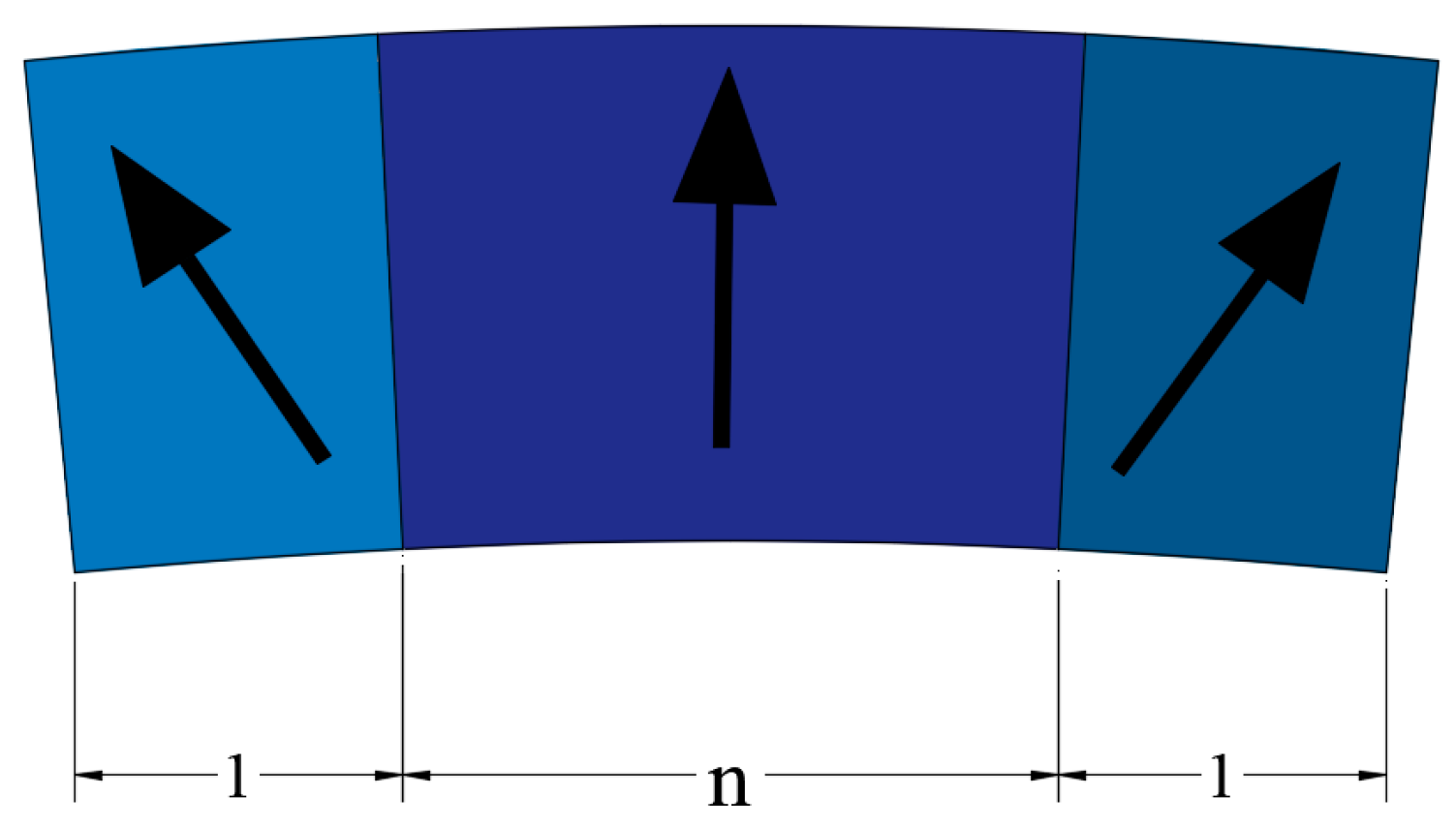
Figure 1b. The unequal blocks of stator PMs are exhibited in
Figure 3 and the fan-shaped structure of PMs is shown in
Figure 4, respectively.
Figure 3 shows the stator PMs are distributed unequally with a ratio of 1:
n:1, and a 60° Halbach array is used. The PMs in
Figure 4 are 90°-magnetized. The arrows represent the magnetization direction of PMs.
3. Performance Analysis
Table 1 provides the EHMG’s details, which were obtained based on experience and reference [
16,
21]. The performance of the suggested and conventional EHMGs was analyzed and compared using FE analysis.
3.1. Magnetic Field Analysis
One of the most crucial aspects of EHMG performance is its magnetic field characteristics. The main flux, which assists in the transmission of torque, is the flux that intersects with low-speed rotor PMs and stator PMs. The flux that only crosses the low-speed rotor PMs or the stator PMs is referred to as the leakage flux, which is not involved in the transfer of torque. Hence, increasing the main flux while decreasing the leakage flux is required to achieve higher torque.
Figure 5 displays the magnetic flux distribution for the two EHMG models. As can be seen in
Figure 5, in the air gap, where the main flux dominates the bulk of space, the magnetic flux lines gather more densely on the suggested EHMG, and the torque mainly relies on the air gap permeance function in the air gap to modulate the harmonic of the air gap flux density, so as to ensure the consistency of the harmonic pole pairs of the inner and outer PMs, and ensure the transmission of torque. Therefore, it is more favorable for torque transmission when the leakage flux predominates in the yokes, resulting in fewer magnetic flux lines distributed within them, which significantly enhances the utilization of PMs. In addition, it corresponds with the unilateral Halbach array effect.
As shown in
Figure 5, we can see that under the same magnetic flux density, as shown by the scale, the magnetic flux density at the junction of the PMs in the traditional model is stronger, with red and blue being more prominent in the figure. In the proposed model, the magnetic flux density between PMs is relatively weak, with fewer red and blue colors in the figure. In the proposed model, it is only due to the effect of the Halbach array that the magnetic flux density on one side (the air gap side) is enhanced, while it is appropriately reduced at the iron yoke and the junction of the PMs. This precisely enhances the magnetic field cross-linking between the inner and outer PMs, and under the modulation of the air gap permeability function, it better transmits torque while also reducing the demagnetization risk of the PMs. In addition, the rare-earth PM NdFeB has the advantages of high magnetic properties, strong machinability, and high cost-effectiveness, and is not easily demagnetized. Its magnetic permeance coefficient is mainly affected by multiple factors such as chemical composition, microstructure, magnetization process, and temperature, so it is not significantly affected by the wide air gap side.
Since flux density is a vector, decomposing it into radial and tangential components can allow a better analysis of its characteristics. By choosing a circular arc in the air gap, the tangential and radial air gap flux density can be analyzed. The consequences are exhibited in
Figure 6.
The consequences illustrate that there are 15 troughs and peaks in flux density throughout an electric cycle, which corresponds to the transmission ratio. The radial flux density of the presented EHMG is much higher than that of the conventional EHMG, as shown in
Figure 6a. At roughly 30° and 330° electrical angles, the maximal radial flux density exceeds 1.25 T. As shown in
Figure 6b, although the tangential flux density of the proposed EHMG is smaller than that of the conventional EHMG at very few angular positions, the overall tangential flux density of the proposed model is still larger than or close to that of the conventional model at most other angular positions. As a consequence, the suggested EHMG model may successfully increase the flux density.
Based on the principle of torque generation, only when two magnetic fields with identical pole pairs interact are they capable of transmitting torque steadily. The modulation effect of harmonics in the air gap permeance function accounts for how regularly the unequal pole pairs of inner and outer PMs may accomplish torque transmission and energy conversion. The coupling of spatial harmonics with the same pole pairs and same speeds may generate the working torque, but the interaction between the spatial harmonics with the same pole pairs while at different speeds will cause torque ripple. Consequently, it is imperative to analyze the space harmonics’ pole pairs. MATLAB software was used to carry out a Fourier analysis on the tangential and radial flux density.
Figure 7 shows the harmonic pole pair distribution spectrum of flux density. Only 60 harmonic orders were gathered for convenience of analysis because, as harmonic pole pairs grow larger, their amplitudes grow smaller and smaller, reducing their influence on electromagnetic torque.
The space harmonics are mostly made up of 14th, 15th, 16th, 44th, 45th, and 46th, as seen in
Figure 7. EHMG flux density space harmonics can be decomposed into pole pairs of 15 and 45 harmonics, representing the fundamental and third components, respectively. The working torque is effectively formed by the fundamental components, not the third harmonic components, which is inactive in this process. As can be seen from the above,
ps is 16,
p is 15, and
pa is 1. The fundamental component with a harmonic pole pair of 15 is made up of the harmonic components from the low-speed rotor and the stator that are modulated by the air gap. Meanwhile, the harmonic pole pair of 16 comprises two parts: the harmonic component from the stator and the harmonic component from the low-speed rotor that are modulated by the air gap. Lastly, the low-speed rotor modulated by the air gap forms the fundamental component with a harmonic pole pair of 14. Working torque is formed by the three fundamental components.
Figure 7 illustrates how the fundamental components of the presented model greatly improved when compared to the conventional EHMG. Similar to the fundamental components, the third components will likewise be produced appropriately but will not be involved in the creation of working torque. The 44th and 46th harmonics diminish, despite the fact that the 45th harmonic also rises. The suggested EHMG is generally useful for increasing working torque.
3.2. Torque Analysis
One of the most significant aspects of EHMG performance is the torque. It is indispensable to analyze the torque.
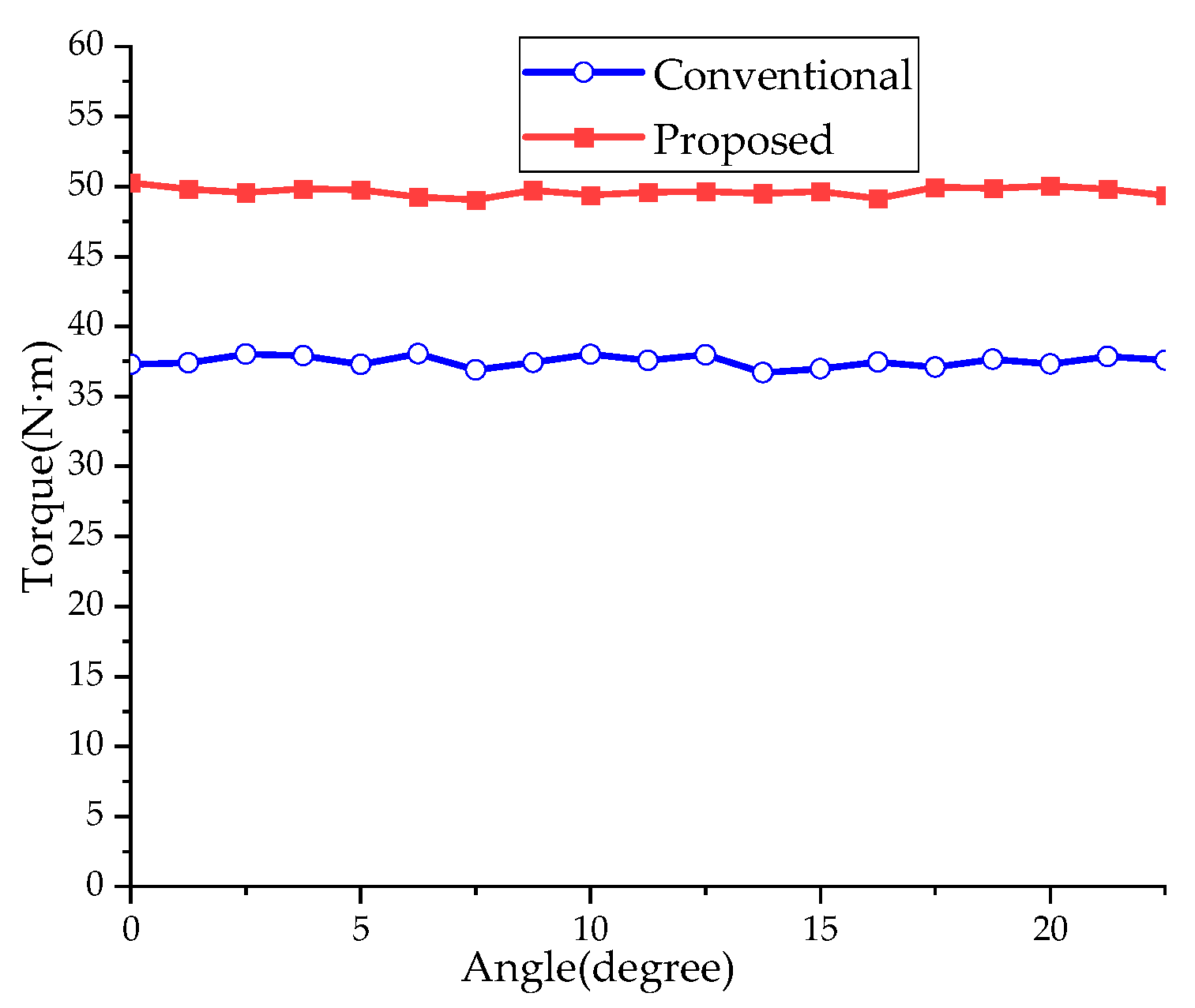
Torque can be divided into static torque and steady-state torque. The static torque can be determined by keeping the high-speed rotor stationary while the low-speed rotor rotates around the stator’s axis for an electric cycle, which is exhibited in
Figure 8. The steady-state torque may be attained by recording the torque value every 1.25° while the low-speed rotor revolves from 0° to 22.5° by spinning the high-speed rotor around the stator axis at a speed of 1500 rpm and the low-speed rotor revolves around its axis in the opposing direction at a speed of 100 rpm, as illustrated in
Figure 9.
According to
Figure 8, the curve of static torque is a typical sine wave. The highest static torque of the conventional model is 38.04 Nm, whereas the maximum static torque of the presented EHMG is 50.41 Nm. It is evident that the suggested EHMG’s output torque rose by 32.5%. The torque density was also raised by 32.5% as a result of the identical mass and volume of the conventional and suggested EHMGs. The maximal static torque corresponds to the highest load that the EHMG can bear. The magnetic gear will become unstable over this number. To put it another way, the load capacity of the presented EHMG is higher than that of the conventional EHMG.
As illustrated in
Figure 9, it can be seen that the value of the steady-state torque is basically consistent with the amplitude of the static torque. Moreover, another key benefit of EHMG is that the torque ripple is extremely low in the EHMG. Even so, the presented EHMG has a lower torque ripple than the conventional model. Consequently, the proposed EHMG has a better, smoother operation.
Compared with conventional models, the proposed model has both advantages and disadvantages, mainly reflected in the following aspects: due to changes in the shape of PMs and the use of a Halbach array, the cost of PMs inevitably increases. In this paper, the cost increased by approximately USD 400. In terms of the usage of PMs, the proposed model concentrated the magnetic field towards the air gap side, which was more conducive to the modulation effect of the air gap and better transmitted torque, thus improving the usage of PMs; in terms of air gap flux density and output torque, the proposed model had a positive effect, that is, increasing the air gap magnetic density led to an increase in the output torque. In addition, it also reduced the torque ripple.
3.3. Modal Analysis
Although an MG has the merits of no friction and low noise compared with mechanical gear, an EHMG will inevitably produce vibration and noise. When an MG gets close to its natural frequency, resonance will occur, giving rise to great noise and deformation. In order to better study the inherent characteristics of an EHMG and avoid the disastrous impact caused by resonance on EHMGs, it is essential to obtain the natural frequency and modal shape through a modal analysis of the EHMG.
To carry out modal analysis, it is necessary to understand the cause and effect of gear vibration noise. The gear vibration noise mainly consists of the following three parts: air vibration noise, mechanical vibration noise, and electromagnetic vibration noise. Air vibration noise is generally generated by the surrounding air rotating with the gear, which can be almost ignored. Mechanical vibration noise is mainly caused by the manufacturing process, which can be avoided by improving the processing accuracy and process level. Electromagnetic vibration noise is mainly generated by the electromagnetic force in the MG. On the one hand, the electromagnetic force will generate the torque that makes the gear rotate; on the other hand, it can also cause rotor deformation and vibration, thus generating noise and vibration. Hence, the study of MG vibration mainly focuses on electromagnetic vibration noise.
During the operation of an EHMG, tangential electromagnetic force density will produce electromagnetic torque, while radial electromagnetic force density will cause gear deformation, vibration, and noise.
In accordance with the Maxwell tensor method, the tangential and radial electromagnetic force density [
17] can be obtained:
where
Br and
Bt represent the radial and tangential magnetic induction intensities, respectively;
μ0 is the vacuum magnetic permeability.
The FE method was used to calculate the space distribution of the radial electromagnetic force density at no-load, as shown in
Figure 10. Since the radial electromagnetic force density is a vector, the positive and negative only represent the opposite direction. It can be seen that in a cycle, the radial electromagnetic force density of the proposed EHMG was reduced by 60.06% compared with the conventional model, and it means that it will be more difficult to cause deformation, vibration, and noise using the presented EHMG.
To conduct a modal analysis, firstly, import the 3D model of the EHMG into the Ansys Workbench software, and then assign the material properties attributes to the EHMG. Finally, by imposing fixed constraints on the stator, the modal shapes and the natural frequencies of the rotor at different orders can be obtained, which are shown in
Figure 11. The material properties of different orders are shown in
Table 2.
As can be seen in
Figure 11, with the order increasing, the natural frequency of the rotor became larger, making it more difficult to excite the vibration mode, and the modal shapes of the higher natural frequencies became more complex. As is exhibited in
Figure 11a, the modal shape of the rotor was similar to an oval, the natural frequency was 4394.3 Hz, and the corresponding maximum deformation was 0.057975 m; in
Figure 11b, the modal shape of the rotor was similar to a triangle, the natural frequency was 11,930 Hz, and the corresponding maximum deformation was 0.064766 m. The number of angles of different modal shapes was related to their respective orders. In
Figure 11c, the modal shape had four angles, which was consistent with the fourth order; the corresponding deformation was 0.068308 m; and, similarly, the fifth-order modal shape had five angles, the sixth-order modal shape had six angles, and the corresponding maximum deformation also increased, as is exhibited in
Figure 11d, e. The natural frequencies of the fourth to sixth orders were 21,716 Hz, 33,635 Hz, and 45,884 Hz, respectively. The natural frequencies of different orders are shown in
Table 3. It is obvious that with the increase in natural frequency, the corresponding maximum deformation also increased. Although the deformation caused by the vibration of high-order natural frequency was large, most of it disappeared in a very short time; hence, the modal shapes and natural frequencies of the low-order modes are the most important. Among the first two orders of vibration, the minimum natural frequency of the rotor was 4394.3 Hz for the second order and 11,930 Hz for the third order. Hence, it is necessary to avoid making the frequency of the gear reach this value as much as possible to reduce the possibility of resonance. In addition, the radial electromagnetic force density of the proposed EHMG was smaller than that of the conventional model, making the proposed model have better antivibration performance compared to the conventional model.
4. Experiments
To verify the analysis and simulation results of the proposed model, a prototype was manufactured and experiments were carried out, as shown in
Figure 12.
The prototype test bench consisted of a DC drive motor, a torque meter, and an EHMG. As a driving motor, a DC motor was connected to the high-speed rotor of the EHMG through a torque sensor, which could measure the speed and torque of the EHMG. The sensitivity of the torque meter (torque meter FTE) was 1.5 mV/V; as for the accuracy, there were multiple ranges to choose from, mainly including the following: 0–0.2 Nm, 0–0.5 Nm, 0–1 Nm, 0–2 Nm, 0–3 Nm, 0–5 Nm, 0–10 Nm, 0–20 Nm, 0–30 Nm, 0–50 Nm, and 0–100 Nm. In this paper, we mainly used the 0–100 Nm range for testing. The DC drive motor had excellent starting characteristics, and after starting the equipment, they could drag the high-speed rotor to rotate, thus starting the EHMG. By recording the torque values at different speeds and comparing them with the torque values obtained with the FE method in this paper, the results are shown in
Figure 13.
As can be seen in
Figure 13, the torque obtained from the FE simulation was about 50.4 Nm, while the torque measured from the experiments was about 48.8 Nm; the data obtained from the experiments were generally smaller than those obtained from the FE simulation. This is because the experimental platform can inevitably generate errors—while the FE simulation is conducted under idealized parameters—but overall, it is not significantly different from the FE method in terms of numerical values within the error range; in other words, the test results are basically consistent with the simulation results, indicating the effectiveness of this experiment.
In order to verify the efficiency of the EHMG, load tests were conducted in this paper, recording the input torque and output torque at different speeds. The efficiency is the ratio of output torque to input torque.
Figure 14 shows the transmission efficiency curve of the proposed EHMG. It can be seen that the operating efficiency of the proposed EHMG was stable, and the efficiency reached 92%.


