Article

Design and Experimental Testing of an Ankle Rehabilitation Robot

by
Ioan Doroftei
1,*,
Cristina-Magda Cazacu
1,* and
Stelian Alaci
2
1
Mechanical Engineering, Mechatronics and Robotics Department, “Gheorghe Asachi” Technical University of Iasi, D. Mangeron Bvd. 43, 700050 Iasi, Romania
2
Mechanical Engineering Department, “Stefan cel Mare” University of Suceava, Universitatii Str. 13, 720229 Suceava, Romania
*
Authors to whom correspondence should be addressed.
Actuators 2023, 12(6), 238; https://doi.org/10.3390/act12060238
Submission received: 2 May 2023 / Revised: 29 May 2023 / Accepted: 6 June 2023 / Published: 8 June 2023
(This article belongs to the Special Issue Advanced Robots: Design, Control and Application—2nd Edition)

Abstract

:
The ankle joint (AJ) is a crucial joint in daily life, responsible for providing stability, mobility, and support to the lower limbs during routine activities such as walking, jumping, and running. Ankle joint injuries can occur due to sudden twists or turns, leading to ligament sprains, strains, fractures, and dislocations that can cause pain, swelling, and limited mobility. When AJ trauma occurs, joint instability happens, causing mobility limitations or even a loss of joint mobility, and rehabilitation therapy is necessary. AJ rehabilitation is critical for those recovering from ankle injuries to regain strength, stability, and function. Common rehabilitation methods include rest, ice, compression, and elevation (RICE), physical therapy, ankle braces, and exercises to strengthen the surrounding muscles. Traditional rehabilitation therapies are limited and require constant presence from a therapist, but technological advancements offer new ways to fully recover from an injury. In recent decades there has been an upswing in research on robotics, specifically regarding rehabilitation. Robotic platforms (RbPs) offer several advantages for AJ rehabilitation assistance, including customized training programs, real-time feedback, improved performance monitoring, and increased patient engagement. These platforms use advanced technologies such as sensors, actuators, and virtual reality to help patients recover quicker and more efficiently. Furthermore, RbPs can provide a safe and controlled environment for patients who need to rebuild their strength and mobility. They can enable patients to focus on specific areas of weakness or instability and provide targeted training for faster recovery and reduced risk of re-injury. Unfortunately, high costs make it difficult to implement these systems in recuperative institutions, and the need for low-cost platforms is apparent. While different systems are currently being used, none of them fully satisfy patient needs or they lack technical problems. This paper addresses the conception, development, and implementation of rehabilitation platforms (RPs) that are adaptable to patients’ needs by presenting different design solutions (DSs) of ankle RPs, mathematical modeling, and simulations of a selected rehabilitation platform (RP) currently under development. In addition, some results from practical tests of the first prototype of this RP are presented. One patient voluntarily agreed to use this platform for more rehabilitation sessions on her AJ (right leg). To counteract some drawbacks of the first prototype, some improvements in the RP design have been proposed. The results on testing the improved prototype will be the subject of future work.

1. Introduction

In recent years, research in the field of medical robotics has been intensified. Among the medical applications of robotics, high-precision surgical interventions or the recovery of motor functions following such interventions or accidents can be mentioned. As benefits of these systems, we can list: they eliminate overburdening of medical personnel, robots reduce waiting times, and physiotherapists can follow several patients at the same time. In addition, the optimization of tools used in surgery and microsurgery facilitates surgical interventions and reduces the incidence of errors and deaths in the scope of high-risk interventions. In conclusion, while doctors can control and monitor more patients with a reduced workload, patients receive better quality medical therapy thanks to modern and efficient equipment.
The structure of the ankle joint (AJ) plays a defining role in an individual’s daily life, providing balance, stability, and the possibility of locomotion. Representing such an important structure in daily activities, the incidence of injuries at the level of this joint, including those of a neurological nature, caused by a stroke, is also high [1]. AJ traumas will immediately affect its stability and mobility. The recovery of the physically injured AJ involves, in the first stage, a reduction in edema: RICE and, possibly, anti-inflammatory drugs. Injured ligaments will form scar tissue, so patients will experience limited activity in the absence of proper rehabilitation. Traditional rehabilitation procedures are based on using simple and primitive devices such as elastic bands and foam rollers. These procedures need the permanent presence of the physiotherapist near the patient. In addition, the used exercises are time-consuming and repetitive, requiring effort both from the physiotherapist and from the patient. To counteract these aspects and to improve the quality of rehabilitation, in recent years, robots have been involved in rehabilitation therapies. The use of robots in such therapies is also based on the increasing number of elderly people who need assistance either due to aging or accidents.
Due to the multiple traumas that can appear at the lower limb, a large diversity of robotic systems have been designed for medical recovery, including AJ RPs. These devices are designed to improve the motor function of the ankle joint, which can be impaired due to various reasons, such as injury, disease, or aging. Typically, AJ RPs have two degrees of freedom (DOF) to enable dorsiflexion (DF)/plantar flexion (PF) and inversion (INV)/eversion (EV) movements. Some robots also include a third DOF to allow for abduction/adduction rotation. Examples include the ankle rehabilitation robot developed by Park et al. [2]. These robots can be classified into different categories based on their design, such as parallel devices, exoskeletons, or wearable devices.
Parallel devices are the most common type of AJ rehabilitation robots (RRs). They typically consist of two platforms, one fixed and one movable, connected by parallel linkages, providing multiple DOF for the ankle joint. Actuation is usually provided by electric motors or pneumatic actuators. Several studies have been conducted to evaluate the effectiveness of parallel AJ RRs in clinical settings. For example, a study by Kesar et al. [3] evaluated the Anklebot, a parallel robot for ankle rehabilitation, in stroke patients and found significant improvements in motor function. Another study by Lee et al. [4] developed an AJ rehabilitation robot (RR) using pneumatic artificial muscles and demonstrated improved ankle DF and PF in stroke patients.
Exoskeletons are another type of AJ RRs that provide support and assistance to the ankle joint through wearable robotic devices. They typically consist of rigid structures attached to the leg and foot, with actuators and sensors providing joint motion and feedback. A study by Lobo-Prat et al. [5] evaluated an ankle exoskeleton for gait rehabilitation in stroke patients and found improved ankle DF and reduced compensatory movements.
Wearable devices are a newer type of AJ RRs that are designed to be lightweight and portable, allowing patients to use them during daily activities. A study by Cheung et al. [6] developed a wearable AJ RR with self-aligning joints and found improved ankle DF and PF in healthy individuals.
Control strategies for AJ RRs play an important role in their effectiveness. Several studies have explored different control strategies, such as impedance control, admittance control, and trajectory tracking control. A study by Paradiso et al. [7] developed a robotic device for ankle rehabilitation with impedance control, while a study by Park et al. [8] developed a gait-enhancing mobile shoe using machine learning algorithms to adapt to each patient’s unique gait. Table 1 summarizes some of the existing parallel AJ RRs, based on: actuation type, number of DOF, control strategies, and study with patients [9].
Unfortunately, robotic-assisted rehabilitation therapies at the level of recuperative institutions are highly costly. That is why research is needed for the development of robotic RPs that can allow therapy to be performed in the patient’s home. Home-based AJ RRs is a growing field, as they offer patients more convenient and accessible options for rehabilitation. We may analyze these robots in terms of different aspects such as robot design, user interface, control strategies, clinical validation, and so on.
In terms of robot design, we may present some examples: Hong et al. [24] developed a portable and lightweight AJ RR that could be easily used at home by stroke patients; Liu et al. [25] designed a 3-DOF wearable AJ RR that could be easily worn by patients during their daily activities; and Zhou et al. [26] developed a modular AJ RR that could be customized based on the patient’s needs and preferences.
Concerning the user interface, Aghaebrahimian et al. [27] developed a smartphone-based user interface for an AJ RR, allowing patients to monitor their progress and receive feedback on their rehabilitation; Kamal et al. [28] designed a gamified user interface for a home-based AJ RR, making rehabilitation more engaging and motivating for patients; and Wang et al. [29] developed a user-friendly interface for an AJ RR, allowing patients to easily adjust the robot’s settings and track their rehabilitation progress.
Regarding clinical validation, Chen et al. [30] conducted a clinical study on a home-based AJ RR with 24 stroke patients and found that the robot was effective in improving the patients’ ankle range of motion and gait performance; Li et al. [31] conducted a randomized controlled trial on a home-based AJ RR with 60 ankle sprain patients and found that the robot-assisted rehabilitation group had better ankle function than the control group; and Wang et al. [32] conducted a pilot study on a home-based AJ RR with 12 ankle sprain patients and found that the robot was effective in improving the patients’ ankle strength and range of motion.
Overall, home-based AJ RRs have the potential to improve patient outcomes by providing more accessible and convenient rehabilitation options. However, more research is needed to validate their effectiveness and usability in clinical settings. Table 2 presents some AJ RPs suggested for domestic use, taking into account actuation type, number of DOF, and the main function of the developed rehabilitation systems [33].
The analysis of the existing literature allows us to conclude that using robotic systems (RbSs) as an innovative substitute for traditional medical treatment is highly advantageous. Nonetheless, rehabilitation systems are faced with certain shortcomings which restrict their usage in recovery clinics, including poor interaction of the patient with the rehabilitation system, the need for additional safety measures during exercises, the inability to repeat sessions at home, limited real-time adjustment options, complex command interfaces, and difficulty handling the systems due to shape and dimension constraints. To overcome these limitations, specialized control techniques are necessary to ensure patient safety and recovery throughout system usage. Control algorithms aim to monitor RbPs used in rehabilitation exercises to enhance motor plasticity and improve motor function recovery. Despite the availability of numerous recovery systems in the literature, a device that satisfies all patient requirements and lacks technical issues does not yet exist. Hence, this study focuses on designing, developing, and implementing adaptable RPs tailored to patients’ specific demands.
The remainder of this paper is organized as follows: Section 2 discusses the design of an ankle RP, including the motivation of the chosen design solution (DS), structural synthesis, design solutions (DSs), and the selection of a platform that will be practically realized. Section 3 presents mathematical modeling and simulation of the adopted DS, its dimensional synthesis, and experimental results during the test; in addition, this section presents some ethical and safety issues and a new proposed design, based on the conclusions that result from the practical test. In Section 4, some concluding remarks of this work are presented.

2. Materials and Methods

2.1. Design of the Ankle Rehabilitation Robot

2.1.1. Motivation of the Adopted Solutions

The AJ is very important both in a person’s daily activities and in sports activities. Due to the fact that it is in great demand throughout the day, this joint can be subject to accidents. Although, in addition to classical therapies, many clinics use robotic systems for the rehabilitation of the AJ, these systems are either too complex, requiring the presence of a physiotherapist; boring and tiring, decreasing patients’ motivation to use them; or too expensive to be purchased by patients in order to carry out recovery sessions at home. Starting from these aspects, there is the need to design robotic platforms that are as simple and friendly as possible, as well as at a low-cost price. In an attempt to design and create a robotic platform for the AJ, the authors of this paper have carried out various studies over the last few years [46,47,48,49,50,51].

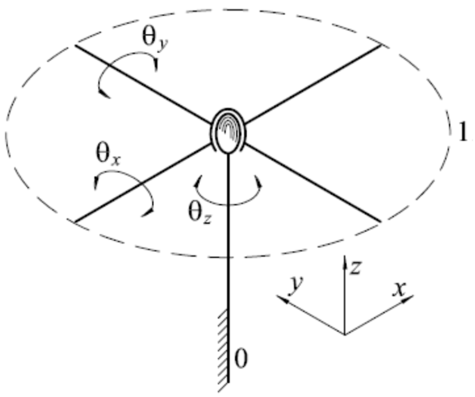
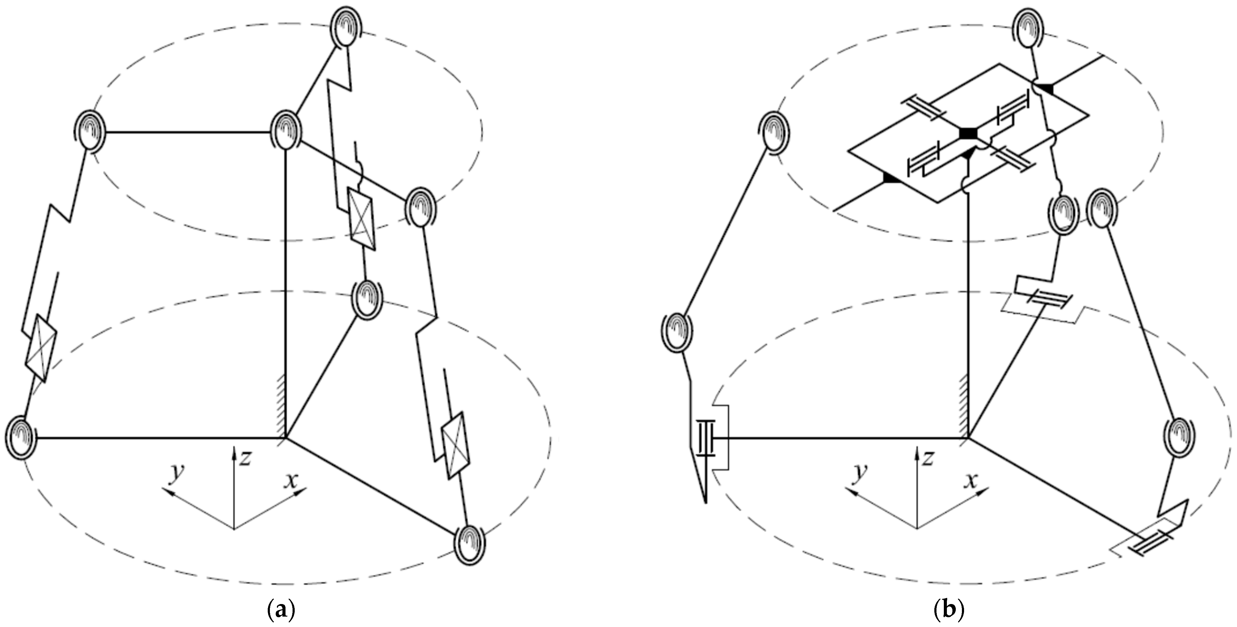
2.1.2. Structural Synthesis

Taking into account the movements allowed by the AJ (Figure 1), we started the design of the robotic RP. This platform should be able to recover two of the three movements shown in Figure 1: DF/PF and EV/INV. The third movement allowed by the AJ (abduction/adduction) is not a key element in the rehabilitation of this joint, with it being a secondary movement. The ranges of the specified movements vary between 25° to 50° for PF, 20° to 30° for DF, 35° to 50° for INV, and 0° to 25° for EV [52]. We may conclude that the designed platform must be a spatial kinematic structure and it should allow two rotational movements around two perpendicular axes. This means that the driven link (DnL) of the RP must have two DOF. This link will be the plate supporting the sole of the foot (PSSF).
Based on the previous comments, some mechanisms with two DOF will be proposed for the AJ RP. “Fixed” RP versions with the base connected to the ground and also “portable” RP versions with the base connected to the calf will be proposed. For all of these RPs, the DnL will be the PSSF. None of the two types of RP may be used during walking. However, the “portable” versions could be displaced, before, during, or after the rehabilitation process. If we consider the DnL of a mechanism that represents the structure of an AJ RP, this link should have three DOF if all three movements of the AJ are intended to be recovered (Figure 2).
We may find multiple actuating solutions of the DnL with three DOF. One of them could use a 3-SPS/S (spherical—prismatic—spherical/spherical) mechanism (see Figure 3a). The prismatic joints of this mechanism will be driving joints (DgJs). A second possible solution is using a 3-RSS/S (rotational—spherical—spherical/spherical) mechanism, shown in Figure 3b. In this case, DgJs are the revolute joints.
Because we considered that the abduction/adduction movement of the AJ is a secondary one and we do not take it into account for recovery, the DnL (the PSSF) could only have two DOF (Figure 4).
We may use multiple actuating solutions of a DnL with two DOF, too. A first example is considering a mechanism such as 2-SPS/U (spherical—prismatic—spherical/universal), as shown in Figure 5a. To avoid rotation around its own axis of the SPS type kinematic chain, a 2-UPS/U (universal—prismatic—spherical/universal) mechanism may be utilized (Figure 5b). The actuation of prismatic joints usually requires linear actuators or rotary actuators and additional mechanical transmissions. For the linear actuators, we may use pneumatic or hydraulic actuators, but they require an external fluid source, which is not usually available at home. Moreover, pneumatic and hydraulic actuators exhibit nonlinearities in their operation. Mechanical transmissions are used to convert the rotational motion into a translational one (ball screw; rack and pinion). These transmissions are complicated and expensive. To counteract all the disadvantages mentioned above, we will propose an RP based on a Scotch–Yoke mechanism. This mechanism has advantages such as a high output torque and smooth operation. Two kinematic solutions (KSs) using the Scotch–Yoke mechanism will be proposed in the following. One of these solutions (KS-1), the “fixed kinematic solution”, is shown in Figure 6. It has the base (link 0) fixed to the ground. The DnL 6 plays the role of the PSSF.
The “portable kinematic solution” has the base (link 0) connected to the calf (KS-2; see Figure 7). The PSSF is, again, represented by the DnL 6. During the rehabilitation exercises, the leg should be suspended, with the calf resting on a solid surface (for example, a chair or a sofa). For both KSs mentioned above (KS-1 and KS-2), the driving links (DgLs) are the links 3 and 3′. To produce the INV/EV movement of the AJ, the DnL 6 must be rotated by the angle θ 6 around the x-axis. For performing this, the DgLs will be rotated by the same angle, θ 3 = θ 3 , in the same direction. The PF/DF movement of the DnL 6 (with the angle θ 6 around the y-axis) will be produced when the DgLs is rotated by the same angle but in opposite directions, θ 3 = θ 3 .
A second actuation solution of the DnL with two DOF (Figure 4) could use a 2-RSS/U (rotational—spherical—spherical/universal) mechanism, Figure 8. For this actuation solution, we may have two KSs, too. The first one (KS-3), called the “fixed kinematic solution”, is shown in Figure 9 and the second one, the “portable kinematic solution” (KS-4), is represented in Figure 10. In these cases, the DnL 4 plays the role of the PSSF.
For these last two mechanisms, the INV/EV movement of the AJ is produced when the DnL 4 is rotated by the angle θ 4 around the x-axis. We will determine whether the DgLs will be rotated by the same angle, θ 1 = θ 1 , in the same direction. If the DgLs is rotated by the same angle but in opposite directions, θ 1 = θ 1 , the PF/DF movement of the DnL 4 (with the angle θ 4 around the y-axis) will be produced.

2.1.3. Design Solutions

Some DSs of “fixed” RPs based on the mechanisms discussed above have been analyzed. These designs could have collinear (DS-2, DS-4, DS-6, and DS-8) or parallel (DS-1, DS-3, DS-5, and DS-7) rotational axes of the two actuators. In addition, they could have the two DnL rotational axes coaxial (DS-1, DS-2, DS-5, and DS-6) with the AJ rotational axes or parallel (DS-3, DS-4, DS-7, and DS-8) to them. These DSs are summarized in Table 3 and Table 4. To select the design solution (DS) with the most advantages in use (Table 5), we have analyzed the proposed DSs based on several criteria:
  • RP maintenance (C1)—these criteria take into account the actuator and mechanism type (joints type);
  • Simplicity in use (C2)—ease of programming and use by the end user;
  • RP cost (C3)—takes into account the cost prices of the components;
  • RP overall dimensions (C4)—the overall dimensions and the mass of the platform are very important in choosing the technical solution;
  • Minimum blocking probability (C5)—depends on the joints type;
  • The DnL range of motion (C6)—the RP should cover the range of motion for both AJ movements considered for rehabilitation.
Points from 0 to 5 were awarded for each criterion and for each DS. RPs with the center of the AJ aligned with the rotation center of the robot (DS-1, DS-2, DS-5, and DS-6) have bigger overall dimensions than other platforms. In addition, RPs with collinear rotational axes of the DgLs (DS-2, DS-6, DS-4, and DS-8) have bigger dimensions compared with the platform with parallel rotational axes of these links (DS-1, DS-3, DS-5, and DS-7). DSs based on a 2-RSS/U mechanism (DS-1, DS-2, DS-3, and DS-4) have better maintenance than platforms based on a 2-UPS/U mechanism (DS-4, DS-5, DS-6, and DS-7). These last RPs (with a 2-UPS/U structure) are more expensive due to the ball nut screw transmissions that should be used for the prismatic joint. In addition, the blocking probability of the RPs based on a 2-UPS/U (DS-4, DS-5, DS-6, and DS-7) mechanism is higher. The range of motions for RPs with the center of the AJ not coincident with the rotation center of the robot (DS-3, DS-4, DS-7, and DS-8) is bigger. Among the discussed DSs, two solutions stand out that meet most of the requirements (DS-1 and DS-3). To select the DS which will be practically realized, dimensional synthesis, mathematical modeling, and simulations of the two mentioned DSs have to be carried out.

3. Results

3.1. Mathematical Modeling and Simulation

Only two DSs based on the spatial four-bar mechanism (DS-1 and DS-3) were considered for mathematical modeling and simulation. The first one has two rotational axes coincident with the AJ axes. However, unfortunately, the simulation revealed that the DS-1 design solution, based on the kinematics shown in Figure 9, cannot assure the necessary movement ranges for AJ rehabilitation.

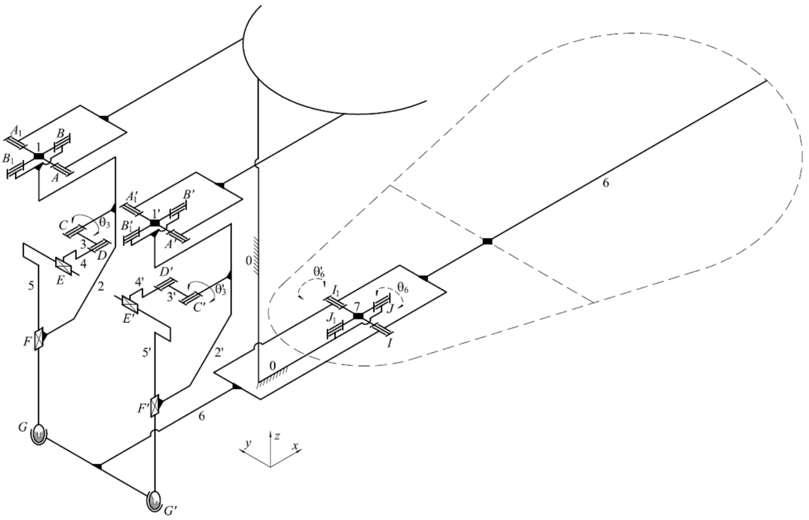
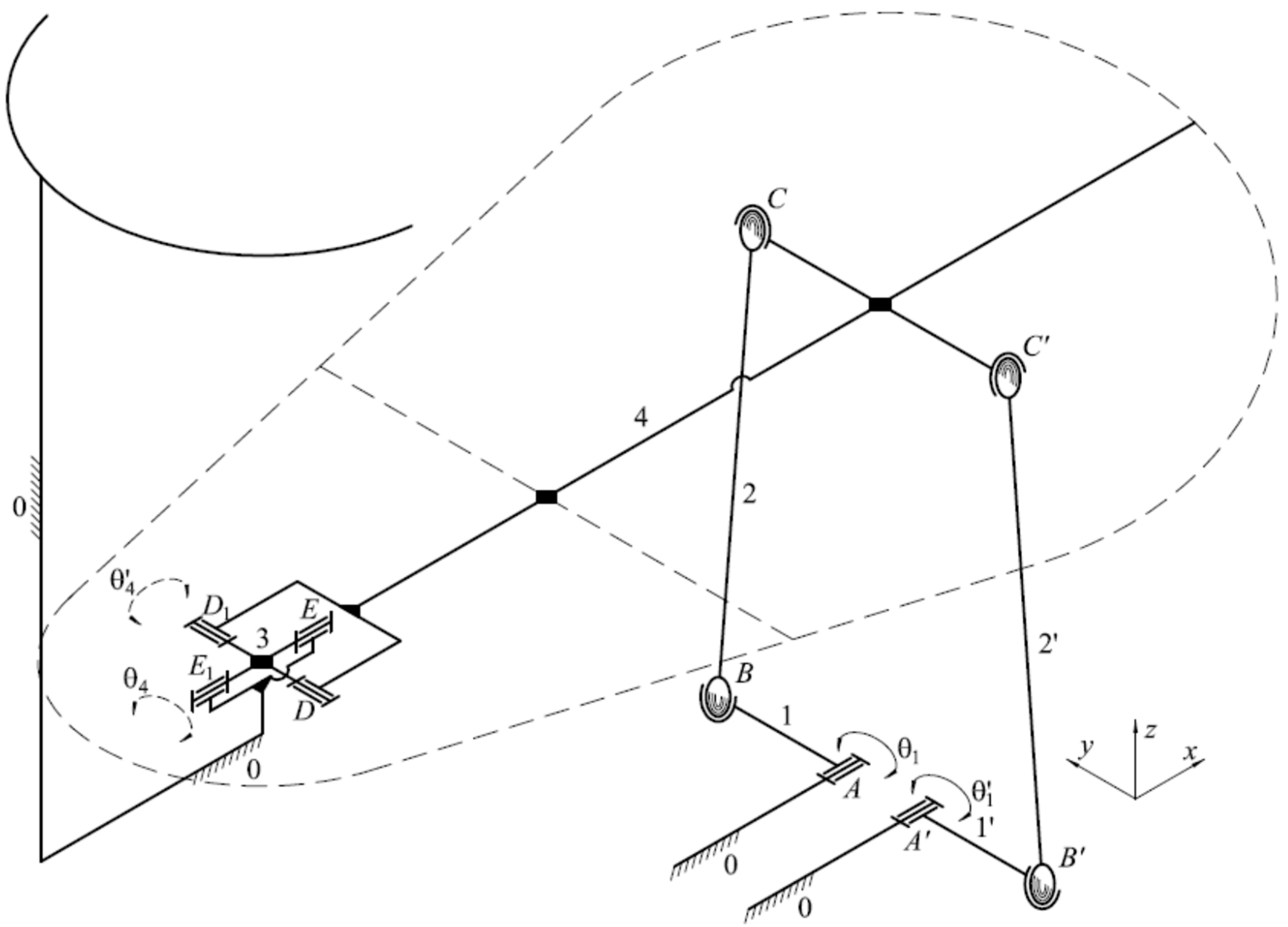
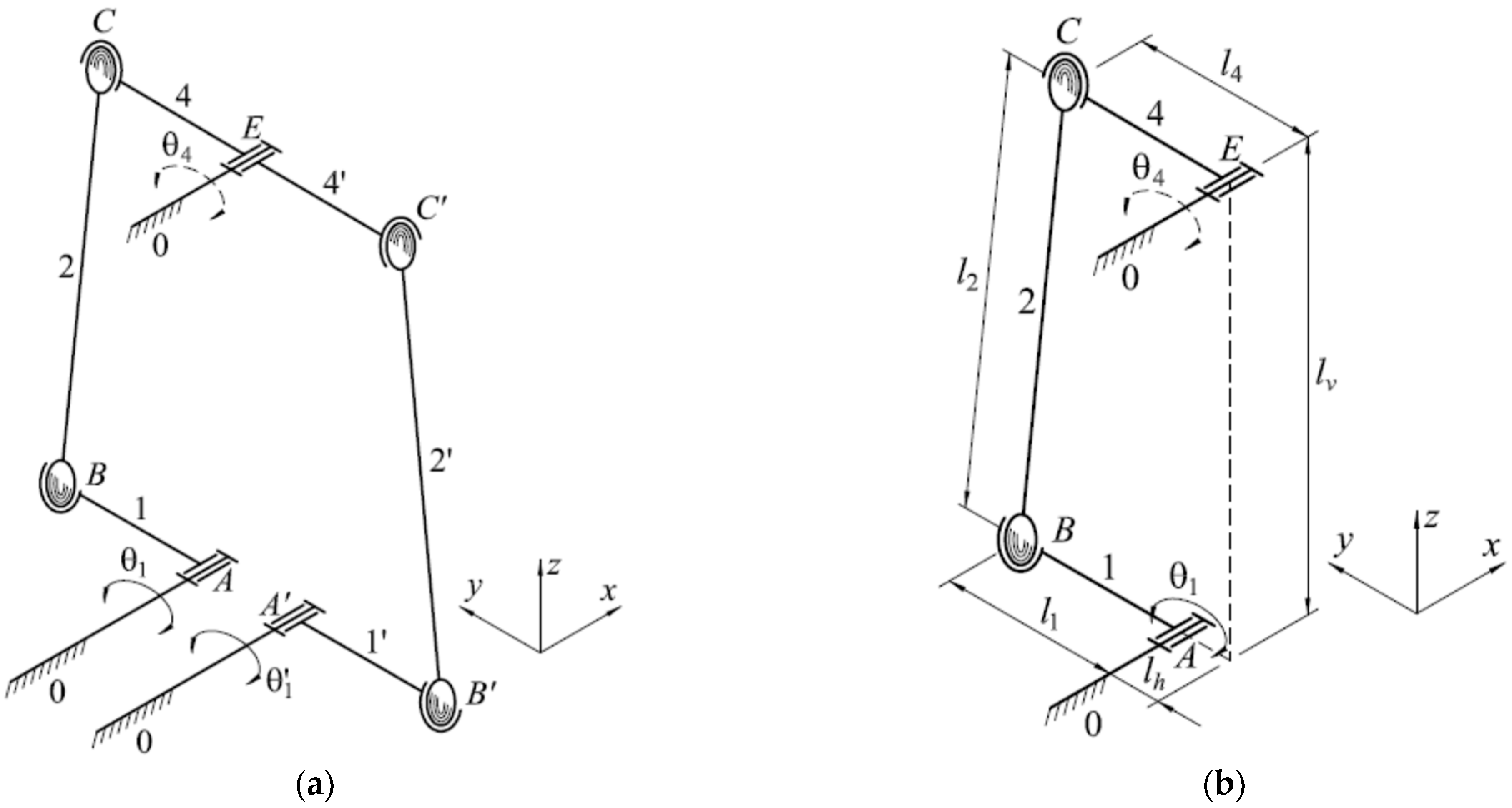
3.1.1. Mathematical Modeling of the DS-3 Design Solution

The kinematics of this DS of the RP is shown in Figure 11. The links 1 and 1′ are DgLs, while the plate 4 represents the DnL. To determine the relationship between the angular position of the DnL 4 with respect to the angular position of the driving link (DgL), the kinematic analysis of the mechanism is required.
The first considered case is that of the INV/EV movement, when both DgLs will be rotated with θ 1 = θ 1 . This movement is produced by the equivalent mechanism shown in Figure 12a. To write the kinematic equations, an equivalent mechanism driven by a single motor (shown in Figure 12b) is used.
The direct kinematics problem will lead to:
θ 4 = 2 · atan ( B 1 ± A 1 2 + B 1 2 C 1 2 C 1 A 1 ) ,
where
{ A 1 = 2 · l 4 · l h 2 · l 1 · l 4 · cos θ 1 B 1 = 2 · l 4 · l v 2 · l 1 · l 4 · sin θ 1 C 1 = 2 · l h · l 1 · cos θ 1 2 · l v · l 1 · sin θ 1 + l 1 2 l 2 2 + l 4 2 + l v 2 + l h 2 ,
while the inverse kinematics problem leads to:
θ 1 = 2 · atan ( B 2 ± A 2 2 + B 2 2 C 2 2 C 2 A 2 )
where
{ A 1 = ( 2 · l h · l 1 2 · l 1 · l 4 · cos θ 4 ) B 1 = ( 2 · l v · l 1 2 · l 1 · l 4 · sin θ 4 ) C 1 = l 1 2 l 2 2 + l 4 2 + l v 2 + l h 2 + 2 · l 4 · ( l v · sin θ 4 l h · cos θ 4 )
We will now consider a mechanism with two DOF (Figure 13a), responsible for PF/DF movement, when the DgLs 1 and 1′ are rotated with θ 1 = θ 1 . To solve the direct kinematics problem, a mechanism with one DOF is used (Figure 13b). By solving the direct kinematics problem for this mechanism, we will obtain:
θ 4 = 2 · atan ( B 3 ± A 3 2 + B 3 2 C 3 2 C 3 A 3 ) ,
where
{ A 3 = 2 · l 4 2 B 3 = 2 · l 4 · l 2 + 2 · l 1 · l 4 · sin θ 1 C 3 = l 1 2 l 2 2 + l 4 2 + l v 2 + l h 2 + 2 · l 4 2 2 · l h · l 4 2 · l 1 · l v · sin θ 1 +   + 2 · l 1 · ( l h l 4 ) · cos θ 1 .
The inverse kinematics problem leads to:
θ 1 = 2 · atan ( B 4 ± A 4 2 + B 4 2 C 4 2 C 4 A 4 ) ,
where
{ A 4 = 2 · l 1 · ( l h l 4 ) B 4 = 2 · l 1 · ( l 4 · sin θ 4 l v ) C 4 = l 1 2 l 2 2 + l 4 2 + l v 2 + l h 2 + 2 · l 4 2 2 · l 4 · ( l 2 · sin θ 4 + l 4 · cos θ 4 ) 2 · l h · l 4 .
Dimensional synthesis of the mechanisms and also a numerical simulation based on these equations must be further carried out.

3.1.2. Dimensional Synthesis and Simulation of the DS-3 Design Solution

For INV/EV movement, a simplified planar mechanism is used, represented by the extreme positions of the DnL (Figure 14a). For anatomical and dimensional reasons, we impose as known dimensions: l h ,   l v and l 4 . The angle θ 4 is also known ( θ 41 for INV and θ 42 for EV). The extreme positions of the crank are defined by θ 11 and θ 12 ( θ 1 = θ 11 + θ 12 ). First, the dimensional synthesis of the mechanism responsible for INV/EV movement (Figure 14a) is solved, with the lengths l 1 and l 2 resulting in:
l 1 = b 2 a 2 2 · b · cos ( ψ + θ 12 ) 2 · a · cos β ,
l 2 = l 1 2 + b 2 2 · b · l 1 · cos ( ψ + θ 12 ) ,
where
a = l h 2 + l v 2 + l 4 2 2 · ( l h 2 + l v 2 ) 1 / 2 · l 4 · cos ( α + θ 41 + θ 42 )
b = l h 2 + l v 2 + l 4 2 2 · ( l h 2 + l v 2 ) 1 / 2 · l 4 · cos α
α = π 2 θ 42 acos ( l v l h 2 + l v 2 )
ψ = π 2 + acos ( l v l h 2 + l v 2 ) acos ( b 2 + l h 2 + l v 2 l 4 2 2 · b · l h 2 + l v 2 )
β = π 2 + acos ( l v l h 2 + l v 2 ) acos ( a 2 + l h 2 + l v 2 l 4 2 2 · a · l h 2 + l v 2 ) θ 11
The geometric synthesis of the mechanism responsible for the PF/DF movement is solved using the simplified mechanism shown in Figure 14b. Based on the previous synthesis, d 1 , e 1 , d 2 , e 2 and l v are known, with:
d 1 = l 1 · sin θ 11 ,
e 1 = l 2 · sin θ 21 ,
d 2 = l 1 · sin θ 12 ,
e 2 = l 2 · sin θ 22 .
The maximum values of the rehabilitation angle θ 4 are also known, considering that we know θ 41 and θ 42 , which are the angular extreme positions of DgL. Following the analytical calculation, the last necessary unknown dimension is obtained, namely:
l 4 = ( d 1 l v ) · sin θ 41 + ( d 1 l v ) 2 · sin 2 θ 41 2 · ( 1 cos θ 41 ) · [ ( d 1 l v ) 2 e 1 2 ] 2 · ( 1 cos θ 41 ) ,
or
l 4 = ( d 2 + l v ) · sin θ 42 + ( d 2 + l v ) 2 · sin 2 θ 42 2 · ( 1 cos θ 42 ) · [ ( d 2 + l v ) 2 e 2 2 ] 2 · ( 1 cos θ 42 ) .
Based on the geometric synthesis and the kinematics problem, a prototype of the RP was designed and is shown in Figure 15, where 1—the base; 2 and 2′—electrical actuators (digital servos HD—1235 MG); 3 and 3′—driving links (the cranks of the two spatial four bar mechanisms); 4 and 4′—the rods of the two spatial four bar mechanisms; 5—driven link (the PSSF); 6 and 7—PSSF encoders; and 8 and 9—DgLs encoders.
To prove that this design solution of the RP provides the DnL with the necessary movement ranges, a simulation of the virtual prototype was performed, using: l 1 = 60   mm ; l 2 = 103   mm ; l 4 = 75   mm ; l h = 25   mm ; and l v = 101.5   mm . A frame was attached to the CAD model with the origin at the center of the AJ, considered at 70 mm above the PSSF, Figure 16. When θ 1 and θ 1 angular positions of DgLs vary between the limits that ensure the two rehabilitated movements, the values of θ 4 and θ 4 are those shown in Figure 17. The surfaces shown in Figure 17 could be considered the RP “workspace”.
Considering that the angular position of the DnL should vary between 25 and 0 for PF and between 0 and 5 0 for DF, the angular position of the DgLs will obtain values as follows: θ 1 = 32.4 ÷ 59 and θ 1 = 59 ÷ 32.4 , θ 1 = θ 1 (Figure 18a). For INV/EV movement, considering that the angular position of the DnL should vary between 50 and 5 0 , in order to assure the rehabilitation of both right and left leg AJs, the angular position of the DgLs should obtain values in the range θ 1 = θ 1 = 73.8 ÷ 73.8 (Figure 18b).
The curve in Figure 18a represents the diagonal of the surface in Figure 17a, when θ 1 = θ 1 , and the curve in Figure 18b represents the diagonal of the surface in Figure 17b, when θ 1 = θ 1 .
The planar curves shown in Figure 19 represent the angular positions θ 4 and θ 4 of the DnL according to the angular position θ 1 of the DgL for PF/DF movement (Figure 19a) and INV/EV movement (Figure 19b). As can be seen in these diagrams, the curves are identical, both for numerical simulation and for virtual RP simulation. The curves represented with a dashed red line represent the planar versions of the spatial curves presented in Figure 18a,b. In Figure 20, the angular positions of the DgLs and driven links (DnLs) are shown according to the time. Their linear variation can be observed, suggesting smooth operation and trouble-free performance of the proposed recovery exercises.

3.2. Experimental Results

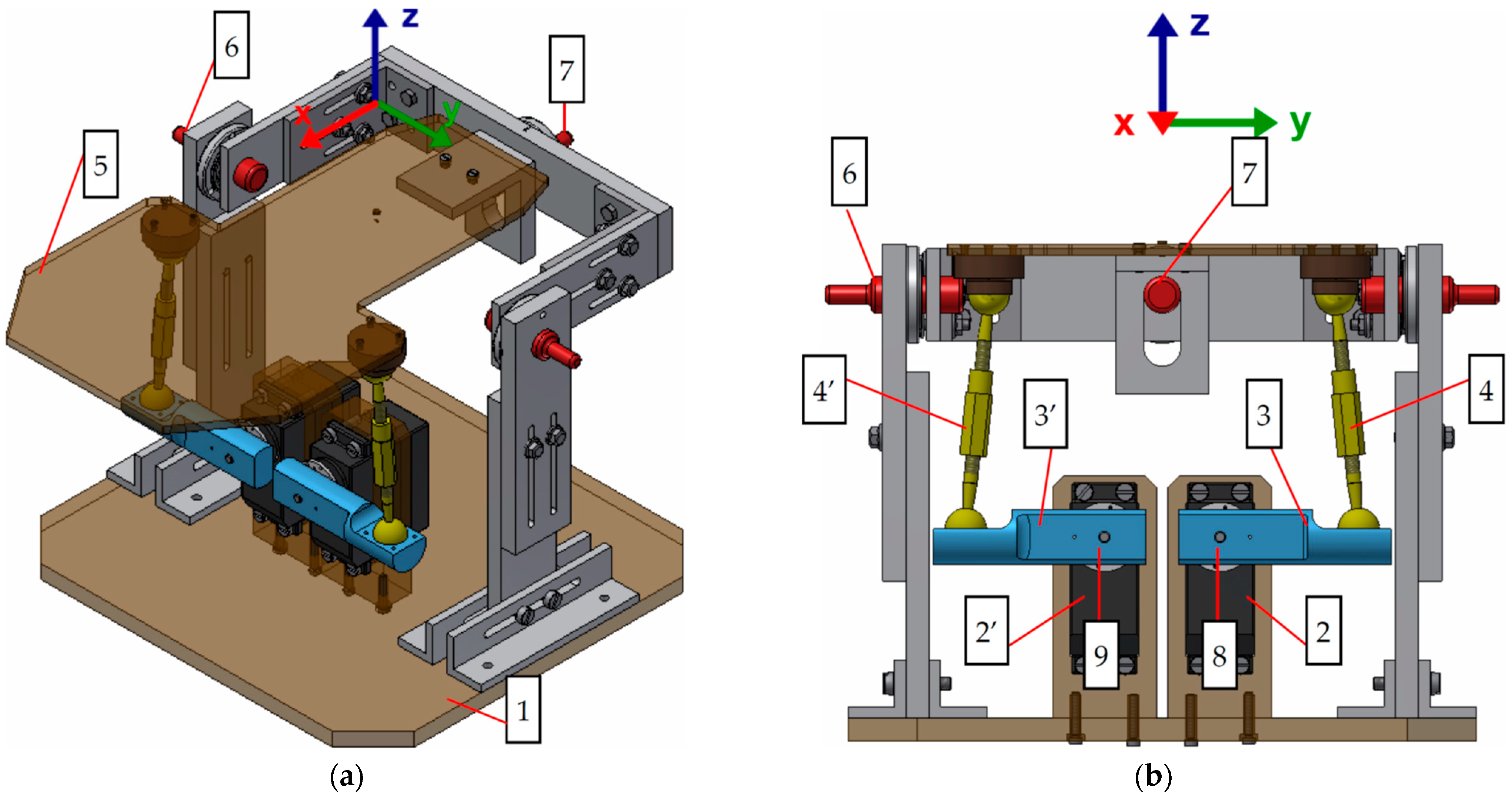
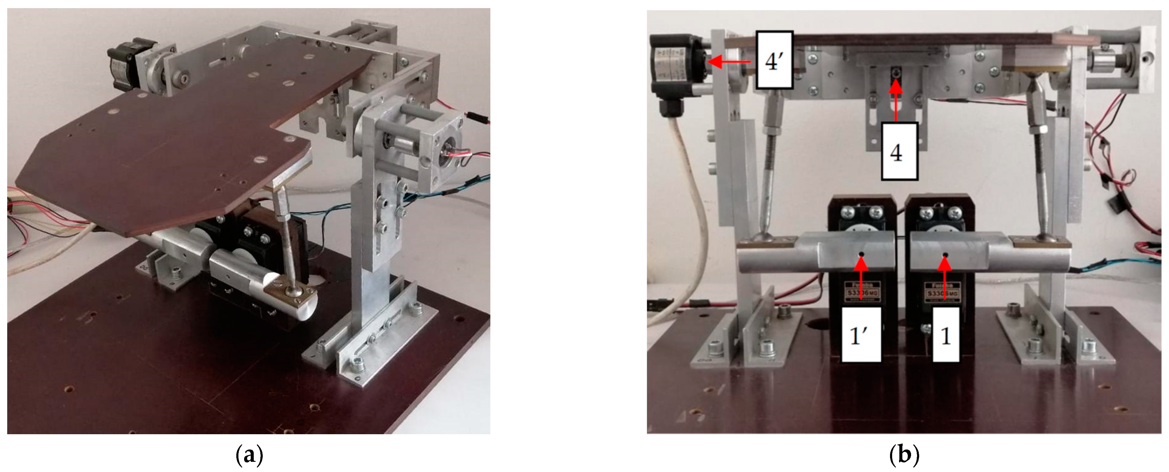
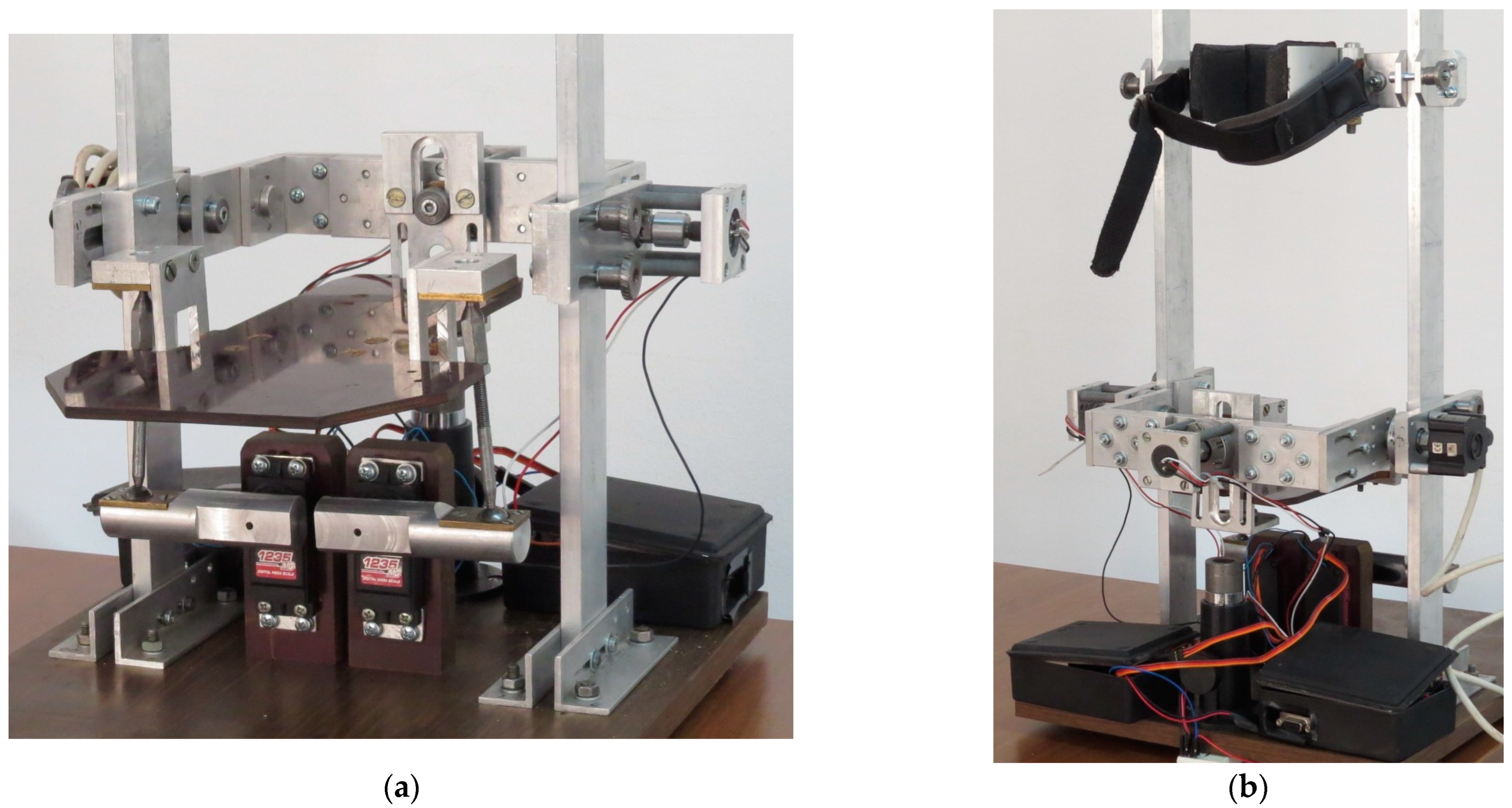
3.2.1. Experimental Platform

The comparative study of the DSs discussed above led to the selection of optimal solutions, which are analyzed later. Thus, out of the two RPs based on the spatial four-bar linkage, only one remained under discussion (DS-3 design solution, Figure 11). This DS was practically realized (Figure 21). The general command and control architecture of the RP is presented in Figure 22. The therapist will set the extreme values of the angular positions for the PSSF through the graphical user interface (GUI), Figure 23. By doing so, the therapist will provide the input data for the microcontroller, according to the necessary rehabilitation exercises. Next, the microcontroller will send commands to the actuators to perform the required movements. Data collected from the encoders will be transmitted to the controller to be analyzed, resulting in visual feedback for both the patient and therapist.
As electric actuators, we have used two digital servos HD—1235 MG. Each one of these servos includes an encoder and its own electronics. These encoders (1 and 1′ in Figure 21) are used to control the angular positions θ 1 and θ 1 of the DnLs, based on the information offered by the two encoders mounted on the rotational axes of the PSSF and also based on the mathematical modeling of the RP. The last two encoders (4 and 4′ in Figure 21) are used to determine the angular positions θ 4 and θ 4 of the PSSF for each PF/DF or INV/EV movement. Through the GUI, the therapist will set the extreme values of θ 4 and θ 4 . To prevent supplementary injuries of the AJ during rehabilitation therapy, the current consumed by the motors is measured and certain limits for this current are imposed in the command/control program.

3.2.2. Experimental Tests and Results

Experimental tests on the RP were performed to evaluate if it may assure the range of angular strokes of the PSSF, according to PF/DF and INV/EV movement requirements. Complete angular strokes were performed for these movements, namely: 25 for PF, 45 for DF, 45 for INV (right leg), and 25 for EV (right leg). Figure 24 shows the values of θ 4 and θ 4 angular positions of the PSSF, relative to the θ 1 angular position of the DgL. These values are monitored during testing (dashed curves in blue). No patients were involved in these tests (the tests were performed without loading of the PSSF). In red, we may see the theoretical curves, generated with the numerical simulation results. Values above 0 for θ 4 (in Figure 24a) correspond to DF movement, while values on the negative axis correspond to PF movement. In Figure 24b, positive values of θ 4 correspond to INV movement, while negative values correspond to EV movement for the right leg. As we can see, the experimental curves are close to those obtained from numerical simulation for both movements that should be recovered.
Next, a volunteer patient with a fracture of the navicular bone in her right leg (Figure 25) was used to test the RP after a 30-day rest period. Due to this long period of immobilization, the patient suffered peripheral edema in the affected leg, walking difficulties and, also, difficulties in performing daily activities due to the increased stiffness of the AJ. Because of that, the physiotherapist recommended several types of PF/DF and INV/EV exercises to her with a frequency of at least once a day. The angular amplitudes of the AJ for the voluntary patient, before starting the therapy, were measured and noted (Figure 26).
Starting from this data, tests were carried out on the RP by progressively increasing the angular amplitudes of the PSSF, accurately finding the range of admissible values for rehabilitation exercises. The patient started the rehabilitation exercises for AJ of the right leg using the following as extreme angular positions: θ 4 = 20 ÷ 2 5 for PF/DF movement and θ 4 = 1 5 ÷ 20 for EV/INV movement (Figure 27). Figure 28 denotes the results obtained during the first day of exercises. Deviations from the simulation results are due to the AJ’s increased stiffness. Each recovery procedure was repeated at least 20 times daily.
Before each session, in order to see if we were able to increase the intensity of the exercises, the patient’s AJ was checked from a physical point of view to see the maximum angular ranges it can develop. After 10 days of therapy, which means half of the recommended recovery period, we were able to observe some improvements in the amplitude of PF/DF and INV/EV movements. More exactly, the range of θ 4 varies between 22 ÷ 30 , and the range for θ 4 is 23 ÷ 30 (Figure 29). We were also able to see that the deviations from the simulation results were much smaller. For the last rehabilitation exercises, we extended the angular extreme positions of the PSSF to θ 4 = 2 5 ÷ 40 for PF/DF movement and θ 4 = 2 5 ÷ 3 5 for INV/EV movement (Figure 30). Comparing Figure 28 and Figure 30, we can observe real progress in the AJ movement recovery, especially for INV/EV, where the stiffness of the joint was greatly increased.
To better see the evolution in the range of motion for both PF/DF and INV/EV movements of the AJ, the curves shown in Figure 28, Figure 29 and Figure 30 are represented together in Figure 31. As we can see, the ranges of θ 4 and θ 4 increase for each new rehabilitation session (starting from the first day—continuous line in red—until the twentieth day—dashed line in green).
Figure 32 also shows the evolution of the AJ recovery results during rehabilitation therapy. The curves represented in this figure highlight the improvements in the AJ mobility at the end of the period, compared to the first day, for both PF/DF and INV/EV movements.

3.2.3. Ethical Issues

Ethical review and approval to use the RP for tests on human participants was not required. The single patient/participant in the study provided her written informed consent to participate. More than this, the patient is the coauthor of this study, and she suffered a fracture of the navicular bone in her right leg during her doctoral studies. She was a researcher and a patient at the same time. At the moment, the authors of this work do not intend to use the robotic platform in hospitals or to market this platform as a final product. Their intention is to improve the design according to the first prototype and its experimental tests to obtain a safe and effective RP.

3.2.4. Safety Issues

To prevent supplementary injuries of the AJ during rehabilitation therapy, the RP should be safe. In case the range of the PSSF angular positions exceeds the mobility range of the injured AJ or if the motors malfunction, they should stop. One possible solution is to measure the current consumed by the motors and to impose certain limits for this current in the command/control program. If the actual consumed current exceeds the limits imposed in the program, the motors should be shut down. This is the solution we are using at the moment. Another safety solution is to use compliant joints between the motors and the DgLs. If the encoders mounted on the output motors shafts send rotational values that exceed the rotational values sent by the encoders mounted on the DgLs, the motors should be shut down. This means that the AJ opposes resistance that exceeds the set value of the torque on the compliant joint. This second solution is intended to be further implemented.

3.3. New Proposed Design

Even though the robotic platform described here has demonstrated benefits for the rehabilitation of the human AJ, the center of the ankle suffers some displacement during exercise (see Figure 33). That is why the calf was not fixed during the rehabilitation exercises (this is the case for Rudgers Ankle [10] or ARBOT [14], etc., too). To avoid these displacements, an optimal RP should have a coincidence between the intersection point of the PF/DF and INV/EV rotational axes and the center of the AJ. To counteract this drawback of the realized RP, a new kinematics of the RP is proposed (Figure 34).
Based on the kinematic diagram shown in Figure 34, a new design for the RP was proposed. As we see in Figure 35, the center of AJ is aligned with the rotation center of the robot, which is the intersection point of the PF/DF and INV/EV rotational axes. In addition, the new robotic platform will enable its use on patients with different anthropomorphic dimensions thanks to its adjustable posture.
To underline the difference between the first prototype (Figure 15) and the new proposed RP (Figure 35), the two platforms are represented in Figure 36. The single difference between the first design and the new one is the shape of the PSSF, noted with 1 (in dark green). The new “U” shape of the PSSF has as an effect lowering of the AJ center of rotation at the intersection point of the two PSSF rotation axes.
The simulation of the new virtual robotic platform reveals that there is not any displacement of the AJ center during rehabilitation (Figure 37). The prototype of the new design is shown in Figure 38. The sole of the foot will be fixed on the plate representing the DnL while the shank will be connected to the robot base (Figure 38b).
During the rehabilitation session, the patient will put their foot on the upper plate of the RP. The position of the PSSF can be adjusted, on z and x axes, so that the AJ rotation centre for different patients can coincide with the rotation centre of the mechanism. Results concerning the simulation of the new virtual robotic platform and also concerning its experimental tests will be the subject of future work.

4. Discussion

When the AJ is injured, it can become unstable, and it can limit mobility or even cause loss of movement. Rehabilitation therapy is necessary to treat these traumas, and traditional therapies typically rely on elastic bands and foam rollers, which require constant assistance from a therapist and are often repetitive and time-consuming. Robotic systems have the potential to assist with AJ rehabilitation, but their high costs make them difficult to implement in recovery institutions. To address this issue, research has been carried out to develop low-cost, high-functionality robotic platforms for ankle rehabilitation and patient monitoring. This paper presents structural synthesis of AJ movements to identify new RP designs. Several solutions were proposed and compared based on a set of criteria, with two standing out as meeting most of the requirements. Dimensional synthesis, mathematical modeling, and simulation were used to select a final variant, with DS-3 based on the spatial four-bar mechanism chosen as the most practical solution.
The first experimental tests were carried out on a volunteer patient, who suffered from stiffness of the ankle joint, following rest from wearing the cast device. The assessment of the patient’s recuperative progress was carried out through the monitoring of the angular strokes achieved by the ankle joint. The experimental results proved the efficiency of the system in patient recovery, as well as the validity of the mathematical model.
Even if the robotic platform described here demonstrated benefits on the rehabilitation of the human AJ, an optimal RP should have the center of the AJ aligned with the rotation center of the robot. This rotation center is the intersection point of the PF/DF and INV/EV rotational axes. Starting from that, a new RP design is proposed. The new RP will be further investigated in future work, including experimental tests. In addition, future studies are currently focused on the implementation of compliant joints between motors and DgLs, which could avoid overloading the ankle joint during rehabilitation exercises.

Author Contributions

Conceptualization, I.D. and C.-M.C.; methodology, I.D., C.-M.C. and S.A.; mathematical validation, I.D. and S.A.; experimental validation, C.-M.C.; investigation, C.-M.C.; resources, I.D. and C.-M.C.; writing—original draft preparation, I.D.; writing—review and editing, I.D.; supervision, I.D.; and project administration, I.D. All authors have read and agreed to the published version of the manuscript.

Funding

This research received no external funding.

Data Availability Statement

Not applicable.

Acknowledgments

This research was supported by the Doctoral School of ”Gheorghe Asachi” Technical University of Iasi, Mechanical Engineering Faculty.

Conflicts of Interest

The authors declare no conflict of interest.

References

  1. Valderrabano, V.; Barg, A.; Paul, J.; Pagenstert, G.; Wiewiorski, M. Foot and ankle injuries in professional soccer player. Sport Orthop. Traumatol. 2014, 30, 98–105. [Google Scholar] [CrossRef]
  2. Park, S.; Hwang, Y.; Kim, H.; Kim, Y. Development of ankle rehabilitation robot with adjustable robotic mechanism. J. Robot. Mechatron. 2016, 28, 157–166. [Google Scholar]
  3. Kesar, T.M.; Perumal, R.; Jancosko, A.; Reisman, D.S.; Rudolph, K.S.; Higginson, J.S.; Binder-Macleod, S.A. Novel patterns of functional electrical stimulation have an immediate effect on dorsiflexor muscle function during gait for people poststroke. Phys. Ther. 2011, 91, 1717–1728. [Google Scholar] [CrossRef] [PubMed] [Green Version]
  4. Lee, H.J.; Kim, Y.; Cho, K.J. Development of a pneumatic artificial muscle-based ankle rehabilitation robot. Int. J. Precis. Eng. Manuf. 2016, 17, 1251–1259. [Google Scholar]
  5. Lobo-Prat, J.; Siviy, C.; Reinkensmeyer, D.J. Design and validation of an ankle foot exoskeleton for running. PLoS ONE 2018, 13, e0201184. [Google Scholar]
  6. Cheung, C.C.; Ng, S.K.; Chan, W.W. Design and control of a wearable ankle rehabilitation robot. IEEE ASME Trans. Mechatron. 2012, 18, 366–375. [Google Scholar]
  7. Paradiso, R.; Marconi, L.; Farina, D. A novel robotic device for ankle rehabilitation. IEEE Trans. Neural Syst. Rehabil. Eng. 2009, 17, 287–295. [Google Scholar]
  8. Park, H.; Jeong, G.W.; Kim, Y.J. Development of a gait enhancing mobile shoe using machine learning algorithms. PLoS ONE 2018, 13, e0201907. [Google Scholar]
  9. Dong, M.; Zhou, Y.; Li, J.; Rong, X.; Fan, W.; Zhou, X.; Kong, Y. State of the art in parallel ankle rehabilitation robot: A systematic review. J. NeuroEng. Rehabil. 2021, 18, 1–15. [Google Scholar] [CrossRef]
  10. Girone, M.; Burdea, G.; Bouzit, M. The Rutgers ankle orthopedic rehabilitation interface. In Proceedings of the ASME Dynamic Systems and Control Division, Nashville, TN, USA, 14–19 November 1999; pp. 305–312. [Google Scholar]
  11. Yoon, J.; Ryu, J.; Lim, K.B. Reconfgurable ankle rehabilitation robot for various exercises: Research articles. J. Robot. Syst. 2005, 22, 15–33. [Google Scholar] [CrossRef]
  12. Dai, J.S.; Zhao, T.; Nester, C. Sprained ankle physiotherapy based mechanism synthesis and stifness analysis of a robotic rehabilitation device. Auton. Robot. 2004, 16, 207–218. [Google Scholar] [CrossRef]
  13. Liu, G.; Gao, J.; Yue, H.; Zhang, X.; Lu, G. Design and kinematics analysis of parallel robots for ankle rehabilitation. In Proceedings of the IEEE/RSJ International Conference on Intelligent Robots & Systems, Beijing, China, 9–15 October 2006; IEEE: Piscataway, NJ, USA, 2006; pp. 253–258. [Google Scholar]
  14. Saglia, J.A.; Tsagarakis, N.G.; Dai, J.S.; Caldwell, D.G. A high-performance redundantly actuated parallel mechanism for ankle rehabilitation. Int. J. Robot. Res. 2009, 28, 1216–1227. [Google Scholar] [CrossRef]
  15. Malosio, M.; Negri, S.P.; Pedrocchi, N.; Vicentini, F.; Caimmi, M.; Tosatti, L.M. A spherical parallel three degrees-of-freedom robot for ankle-foot neuro-rehabilitation. In Proceedings of the Annual International Conference of the IEEE Engineering in Medicine and Biology Society, San Diego, CA, USA, 28 August–September 2012; pp. 3356–3359. [Google Scholar]
  16. Ayas, M.S.; Altas, I.H. Fuzzy logic based adaptive admittance control of a redundantly actuated ankle rehabilitation robot. Control Eng. Pract. 2017, 59, 44–54. [Google Scholar] [CrossRef]
  17. Ai, Q.; Zhu, C.; Zuo, J.; Meng, W.; Liu, Q.; Xie, S.; Yang, M. Disturbance-estimated adaptive backstepping sliding mode control of a pneumatic muscles-driven ankle rehabilitation robot. Sensors 2018, 18, 66. [Google Scholar] [CrossRef] [PubMed] [Green Version]
  18. Jamwal, P.K.; Hussain, S.; Ghayesh, M.H.; Rogozina, S.V. Impedance control of an intrinsically compliant parallel ankle rehabilitation robot. IEEE Trans. Ind. Electron. 2016, 63, 3638–3647. [Google Scholar] [CrossRef]
  19. Zhang, M.; Cao, J.; Zhu, G.; Miao, Q.; Zeng, X.; Xie, S.Q. Reconfgurable workspace and torque capacity of a compliant ankle rehabilitation robot (CARR). Robot. Auton. Syst. 2017, 98, 213–221. [Google Scholar] [CrossRef] [Green Version]
  20. Tsoi, Y.H.; Xie, S.Q.; Graham, A.E. Design, modeling and control of an ankle rehabilitation robot. In Design and Control of Intelligent Robotic Systems; Liu, D., Wang, L., Tan, K.C., Eds.; Springer: Berlin/Heidelberg, Germany, 2009; pp. 377–399. [Google Scholar]
  21. Wang, C.; Fang, Y.; Guo, S.; Chen, Y. Design and kinematical performance analysis of a 3—RUS/RRR redundantly actuated parallel mechanism for ankle rehabilitation. J. Mech. Robot. 2013, 5, 041003. [Google Scholar] [CrossRef]
  22. Valles, M.; Cazalilla, J.; Valera, A.; Mata, V.; Page, A.F.; Diaz-Rodriguez, M. A 3-PRS parallel manipulator for ankle rehabilitation: Towards a low-cost robotic rehabilitation. Robotica 2017, 35, 1939–1957. [Google Scholar] [CrossRef]
  23. Li, J.; Zuo, S.; Zhang, L.; Dong, M. Mechanical design and performance analysis of a novel parallel robot for ankle rehabilitation. J. Mech. Robot. 2020, 12, 051007. [Google Scholar] [CrossRef]
  24. Hong, D.; Gong, M.; Li, S.; Lu, W. Design of a Portable and Lightweight Ankle Rehabilitation Robot for Home Use by Stroke Patients. J. Healthc. Eng. 2020, 1–9. [Google Scholar]
  25. Liu, H.; Jin, R.; Xie, S.; Zhang, X.; Wang, F. Design and Development of a Wearable Ankle Rehabilitation Robot Based on Three-Dimensional Acceleration Sensor. Appl. Sci. 2019, 9, 4058. [Google Scholar]
  26. Zhou, Z.; Jiang, Y.; Huang, H.; Wei, Q. Design and Control of a Modular Ankle Rehabilitation Robot. J. Healthc. Eng. 2019, 1–12. [Google Scholar]
  27. Aghaebrahimian, A.; Abdi, A.; Faraji, M. A Smartphone-Based User Interface for an Ankle Rehabilitation Robot. J. Rehabil. Robot. 2019, 3, 63–70. [Google Scholar]
  28. Kamal, A.; Lemaire, E.D.; Sawan, M. Design and Evaluation of a Gamified User Interface for Home-Based Ankle Rehabilitation. J. Med. Syst. 2021, 45, 1–10. [Google Scholar]
  29. Wang, L.; Chen, C.; Zheng, R.; Liu, H. Design of a User-Friendly Interface for an Ankle Rehabilitation Robot. IEEE Access 2020, 8, 135509–135517. [Google Scholar]
  30. Chen, X.; Chen, S.; Chen, W.; Chen, Y.; Guo, X.; Liu, G. Clinical Efficacy and Safety of Home-Based Rehabilitation for Post-Stroke Ankle-Foot Dysfunction Using Ankle Rehabilitation Robot: A Randomized, Controlled Pilot Trial with 24 Weeks of Follow-Up. Clin. Rehabil. 2018, 32, 1174–1184. [Google Scholar]
  31. Li, R.; Zhang, Y.; Xu, Z.; Li, M. Robot-Assisted Ankle Rehabilitation Training Improves Ankle Function in Patients with Acute Ankle Sprain: A Randomized Controlled Trial. J. Orthop. Surg. Res. 2020, 15, 1–9. [Google Scholar]
  32. Wang, K.; Wang, Z.; Liu, H. Pilot Study on the Clinical Effect of a Home-Based Ankle Rehabilitation Robot. J. Rehabil. Robot. 2018, 2, 31–38. [Google Scholar]
  33. Shah Nazar, P.; Pott, P.P. Ankle Rehabilitation Robotic Systems for domestic use—A systematic review. Curr. Dir. Biomed. Eng. 2022, 8, 65–68. [Google Scholar] [CrossRef]
  34. Cioi, D.; Burdea, G.; Engsberg, J.R.; Janes, W. Ankle control and strength training for children with cerebral palsy using the Rutgers Ankle CP: A case study. In Proceedings of the IEEE International Conference on Rehabilitation Robotics, Zurich, Switzerland, 29 June–1 July 2011; p. 5975432. [Google Scholar]
  35. Roy, A.; Forrester, L.W.; Macko, R. Short-term ankle motor performance with ankle robotics training in chronic hemiparetic stroke. J. Rehabil. Res. Dev. 2011, 48, 417–429. [Google Scholar] [CrossRef]
  36. Kim, J.; Hwang, S.; Sohn, R.; Lee, Y.; Kim, Y. Development of an Active Ankle Foot Orthosis to Prevent Foot Drop and Toe Drag in Hemiplegic Patients: A Preliminary Study. Appl. Bionics Biomech. 2011, 8, 377–384. [Google Scholar] [CrossRef] [Green Version]
  37. Ward, J.; Sugar, T.; Boehler, A.; Standeven, J.; Engsberg, J.R. Stroke Survivors’ Gait Adaptations to a Powered Ankle Foot Orthosis. Adv. Robot. 2011, 25, 1879–1901. [Google Scholar] [CrossRef] [PubMed] [Green Version]
  38. Forrester, L.W.; Roy, A.; Krebs, H.I.; Macko, R.F. Ankle training with a robotic device improves hemiparetic gait after a stroke. Neurorehabilit. Neural Repair 2011, 25, 369–377. [Google Scholar] [CrossRef] [PubMed] [Green Version]
  39. Jamwal, P.K.; Sie, S.Q. An Adaptive Wearable Parallel Robot for the Treatment of Ankle Injuries. IEEE/ASME Trans. Mechatron. 2014, 19, 64–75. [Google Scholar] [CrossRef]
  40. Blanchette, A.K.; Noel, M.; Richards, C.L.; Nadeau, S.; Bouyer, L.J. Modifications in ankle dorsiflexor activation by applying a torque perturbation during walking in persons post-stroke: A case series. J. Neuroeng. Rehabil. 2014, 11, 98. [Google Scholar] [CrossRef] [Green Version]
  41. Takahashi, K.Z.; Lewek, M.D.; Sawicki, G.S. A neuromechanics-based powered ankle exoskeleton to assist walking post-stroke: A feasibility study. J. Neuroeng. Rehabil. 2015, 12, 23. [Google Scholar] [CrossRef] [Green Version]
  42. Koller, J.R.; Remy, C.D.; Ferris, D.P. Comparing neural control and mechanically intrinsic control of powered ankle exoskeletons. In Proceedings of the IEEE International Conference on Rehabilitation Robotics, London, UK, 17–20 July 2017; pp. 294–299. [Google Scholar]
  43. Ren, Y.; Wu, I.N.; Yang, C.Y.; Xu, T.; Harvey, R.L.; Zhang, L.Q. Developing a Wearable Ankle Rehabilitation Robotic Device for in-Bed Acute Stroke Rehabilitation. IEEE Trans. Neural Syst. Rehabil. Eng. 2017, 25, 589–596. [Google Scholar] [CrossRef]
  44. Yeung, L.F.; Ockenfeld, C.; Pang, M.K.; Wai, H.W.; Soo, O.Y.; Li, S.W.; Tong, K.Y. Randomized controlled trial of robotassisted gait training with dorsiflexion assistance on chronic stroke patients wearing ankle-foot-orthosis. J. Neuroeng. Rehabil. 2018, 15, 51. [Google Scholar] [CrossRef] [Green Version]
  45. Awad, L.N.; Esquenazi, A.; Francisco, G.E.; Nolan, K.J.; Jayaraman, A. The ReWalk ReStore™ soft robotic exosuit: A multi-site clinical trial of the safety, reliability, and feasibility of exosuit-augmented post-stroke gait rehabilitation. J. Neuroeng. Rehabil. 2020, 17, 80. [Google Scholar] [CrossRef]
  46. Racu, C.M.; Doroftei, I. Design, modelling and simulation aspects of an ankle rehabilitation device. IOP Conf. Ser. Mater. Sci. Eng. 2016, 145, 052008. [Google Scholar] [CrossRef] [Green Version]
  47. Racu, C.M.; Doroftei, I. Design Aspects of a New Device for Ankle Rehabilitation. Appl. Mech. Mater. 2015, 809, 986–991. [Google Scholar] [CrossRef]
  48. Racu, C.M.; Doroftei, I. Ankle rehabilitation device with two degrees of freedom and compliant joint. IOP Conf. Ser. Mater. Sci. Eng. 2015, 95, 012054. [Google Scholar] [CrossRef] [Green Version]
  49. Racu, C.M.; Doroftei, I. New Concepts of Ankle Rehabilitation Devices—Part I: Theoretical Aspects. In New Advances in Mechanism and Machine Science; Doroftei, I., Pisla, D., Lovasz, E., Eds.; Springer: Cham, Switzerland, 2018; pp. 223–231. [Google Scholar]
  50. Racu, C.M.; Doroftei, I. New Concepts of Ankle Rehabilitation Devices—Part II: Design and Simulation. In New Advances in Mechanism and Machine Science; Doroftei, I., Pisla, D., Lovasz, E., Eds.; Springer: Cham, Switzerland, 2018; pp. 233–239. [Google Scholar]
  51. Racu, C.M.; Doroftei, I. Preliminary results and evaluation of an ankle rehabilitation device. IOP Conf. Ser. Mater. Sci. Eng. 2020, 997, 012088. [Google Scholar] [CrossRef]
  52. Parenteau, C.S.; Viano, D.C.; Petit, P.Y. Biomechanical properties of human cadaveric ankle-subtalar joints in quasi-static loading. J. Biomech. Eng. 1998, 120, 105–111. [Google Scholar] [CrossRef]
  53. Doroftei, I.; Racu, C.M.; Baudoin, Y. Development of a Robotic Platform for Ankle Joint Rehabilitation. Acta Tech. Napoc. Ser. Appl. Math. Mech. Eng. 2021, 64, 301–310. [Google Scholar]
Figure 1. AJ rotational motions.
Actuators 12 00238 g001
Figure 2. Principled schematics of an RP with three DOF.
Actuators 12 00238 g002
Figure 3. Kinematics of a RP with three DOF: (a) an RP using a 3-SPS/S mechanism and (b) an RP based on the 3-RSS/S mechanism.
Actuators 12 00238 g003
Figure 4. Principled schematics of an RP with two DOF.
Actuators 12 00238 g004
Figure 5. Kinematics of an RP with two DOF: (a) an RP using a 2-SPS/U mechanism and (b) an RP based on a 2-UPS/U mechanism.
Actuators 12 00238 g005
Figure 6. Kinematics of the RP based on the Scotch–Yoke mechanism, “fixed” version (KS-1).
Actuators 12 00238 g006
Figure 7. Kinematics of the RP based on the Scotch–Yoke mechanism, “portable” version (KS-2).
Actuators 12 00238 g007
Figure 8. Kinematics of an RP with two DOF with the structure based on a 2-RSS/U mechanism.
Actuators 12 00238 g008
Figure 9. Kinematics of an RP based on the spatial four-bar linkage, “fixed” version (KS-3).
Actuators 12 00238 g009
Figure 10. Kinematics of an RP based on the spatial four-bar linkage, “portable” version (KS-4).
Actuators 12 00238 g010
Figure 11. Kinematics of the DS-3 design solution.
Actuators 12 00238 g011
Figure 12. Equivalent mechanisms for EV/INV movement (DS-3 design solution): (a) mechanism with two DOF and (b) mechanism with one DOF.
Actuators 12 00238 g012
Figure 13. Equivalent mechanisms for PF/DF movement (DS-3 design solution): (a) real mechanism with two DOF [46] and (b) equivalent mechanism with one DOF.
Actuators 12 00238 g013
Figure 14. Simplified planar mechanism for geometric synthesis (DS-3 design solution): (a) for INV/EV movement and (b) for PF/DF movement [46]. In red and blue colors the extreme positions of the mechanisms are represented.
Actuators 12 00238 g014
Figure 15. Three-dimensional CAD design of the RP (DS-3 design solution): (a) isometric view and (b) frontal view.
Actuators 12 00238 g015
Figure 16. Attaching the frame to the DnL 4 (DS-3 design solution).
Actuators 12 00238 g016
Figure 17. Maximum range of the PSSF angular positions according to the angular positions of the DgLs: (a) for PF/DF movement, θ 1 = θ 1 , and (b) for INV/EV movement, θ 1 = θ 1 .
Actuators 12 00238 g017
Figure 18. Angular position of the DnL according to the angular positions of the DgLs: (a) for the actual PF/DF movement, θ 1 = θ 1 and (b) for the actual INV/EV movement, θ 1 = θ 1 .
Actuators 12 00238 g018
Figure 19. Numerical simulation results vs. results of the virtual RP simulation: (a) for PF/DF movement and (b) for INV/EV movement.
Actuators 12 00238 g019
Figure 20. Angular positions of the DgLs and DnLs according to the time: (a) for PF/DF movement and (b) for INV/EV movement.
Actuators 12 00238 g020
Figure 21. Prototype of the RP with two DOF (DS-3 design solution): (a) axonometric view and (b) frontal view.
Actuators 12 00238 g021
Figure 22. General command and control architecture of the RP.
Actuators 12 00238 g022
Figure 23. Graphical user interface.
Actuators 12 00238 g023
Figure 24. RP testing results [53]: (a) for PF/DF movement and (b) for INV/EV movement.
Actuators 12 00238 g024
Figure 25. Fracture of the navicular bone, volunteer patient [53].
Actuators 12 00238 g025
Figure 26. Angular amplitudes of the AJ for the voluntary patient before starting therapy.
Actuators 12 00238 g026
Figure 27. Images recorded during the first rehabilitation exercises of the voluntary patient.
Actuators 12 00238 g027
Figure 28. Results recorded during the rehabilitation exercises—day 1 [53]: (a) for PF/DF movement and (b) for INV/EV movement.
Actuators 12 00238 g028
Figure 29. Results recorded during the rehabilitation exercises—day 10 [53]: (a) for PF/DF movement and (b) for INV/EV movement.
Actuators 12 00238 g029
Figure 30. Results recorded during the rehabilitation exercises—day 20 [53]: (a) for PF/DF movement and (b) for INV/EV movement.
Actuators 12 00238 g030
Figure 31. Results of the three rehabilitation sessions: (a) for PF/DF movement and (b) for INV/EV movement.
Actuators 12 00238 g031
Figure 32. Results of the rehabilitation exercises over time during the therapy period [53]: (a) for PF/DF movement and (b) for INV/EV movement.
Actuators 12 00238 g032
Figure 33. AJ center displacements during rehabilitation—simulation results (DS-3 design solution): (a) for PF/DF movement and (b) for INV/EV movement.
Actuators 12 00238 g033
Figure 34. Kinematics of the new proposed RP.
Actuators 12 00238 g034
Figure 35. Three-dimensional CAD design of the new proposed RP: (a) isometric view and (b) frontal view.
Actuators 12 00238 g035
Figure 36. Three-dimensional CAD of both RPs: (a) the first design and (b) the new design.
Actuators 12 00238 g036
Figure 37. AJ center displacements during rehabilitation—simulation results (new RP design): (a) for PF/DF movement and (b) for INV/EV movement.
Actuators 12 00238 g037
Figure 38. Improved prototype of the RP: (a) front isometric view and (b) back isometric view.
Actuators 12 00238 g038
Table 1. Some existing parallel AJ RPs [9].
ReferenceActuation TypeNumber of DOFControl StrategiesStudy with Patients
Girone et al. [10]Pneumatic6Position control; force controlYes
Yoon et al. [11]Pneumatic4Position controlNo
Dai et al. [12]Electric4N/ANo
Liu et al. [13]Electric3Position control; force controlNo
Saglia et al. [14]Electric2Position control; assistive control; admittance controlNo
Malosio et al. [15]Electric3Position control; admittance controlNo
Ayas et al. [16]Electric2Trajectory tracking; admittance adaptive controlNo
Ai et al. [17]Pneumatic2Adaptive backstepping sliding mode controlNo
Jamwal et al. [18]Pneumatic3Position control; adaptive control; adaptive impedance controlYes
Zhang et al. [19]Pneumatic3Position control; adaptive patient-cooperative control; adaptive trajectory trackingYes
Tsoi et al. [20]Electric3Joint force control; impedance controlNo
Wang et al. [21]Electric3Position controlNo
Valles et al. [22]Electric3Position control; force controlNo
Li et al. [23]Electric3Position control; patient-passive compliant exercise; isotonic exercise; patient-active exerciseNo
Table 2. Some AJ RPs suggested for domestic use [33].
ReferenceActuation TypeNumber of DOFFunction
Cioi et al. [34]Pneumatic6Ankle rehabilitation for children with epilepsy
Girone et al. [10]Pneumatic6AJ rehabilitation
Roy et al. [35]Electric3Ankle training with a robotic device to improve hemiparetic gait after a stroke
Kim et al. [36]Electric2Active ankle–foot orthosis for foot drop
Ward et al. [37]Electric2Powered ankle–foot orthosis
Forrester et al. [38]Electric3“AnkleBot” training on paretic ankle motor control in chronic stroke
Jamwal et al. [39]Pneumatic3Treatment for an ankle sprain through physical therapy
Blanchette et al. [40]Electro-hydraulic2Robotized ankle–foot orthosis
Takahashi et al. [41]Pneumatic2An exoskeleton supplies plantar flexion assistance
Koller et al. [42]Pneumatic2Powered ankle exoskeletons using neural measurements
Ren et al. [43]Electric2Wearable AJ RR for in-bed acute stroke rehabilitation
Yeung et al. [44]Electric2Robot-assisted ankle–foot orthosis to provide assistance post stroke
Awad et al. [45]Electric2ReWalk ReStore dorsi flexor and plantar flexor
Table 3. DSs of robotic RPs with two DOF based on the spatial four-bar linkage (2-RSS/U).
The Center of the AJ Is Aligned with the Rotation Center of the RobotThe Center of the AJ and the Rotation Center of the Robot Are not Coincident
Parallel Rotational Axes of DgLsCollinear Rotational Axes of DgLsParallel Rotational Axes of DgLsCollinear Rotational Axes of DgLs
DS-1
Actuators 12 00238 i001
DS-2
Actuators 12 00238 i002
DS-3
Actuators 12 00238 i003
DS-4
Actuators 12 00238 i004
Table 4. DSs of robotic RPs with two DOF based on the Scotch–Yoke mechanism (2-UPS/U).
The Center of the AJ Is Aligned with the Rotation Center of the RobotThe Center of the AJ and the Rotation Center of the Robot Are not Coincident
Parallel Rotational Axes of DgLsCollinear Rotational Axes of DgLsParallel Rotational Axes of DgLsCollinear Rotational Axes of DgLs
DS-5
Actuators 12 00238 i005
DS-6
Actuators 12 00238 i006
DS-7
Actuators 12 00238 i007
DS-8
Actuators 12 00238 i008
Table 5. Selection of the adopted DS.
DS-1DS-2DS-3DS-4DS-5DS-6DS-7DS-8
C155554444
C255555555
C355554444
C443543243
C544543333
C643534455
Total2725302623222524
Disclaimer/Publisher’s Note: The statements, opinions and data contained in all publications are solely those of the individual author(s) and contributor(s) and not of MDPI and/or the editor(s). MDPI and/or the editor(s) disclaim responsibility for any injury to people or property resulting from any ideas, methods, instructions or products referred to in the content.

