1. Introduction
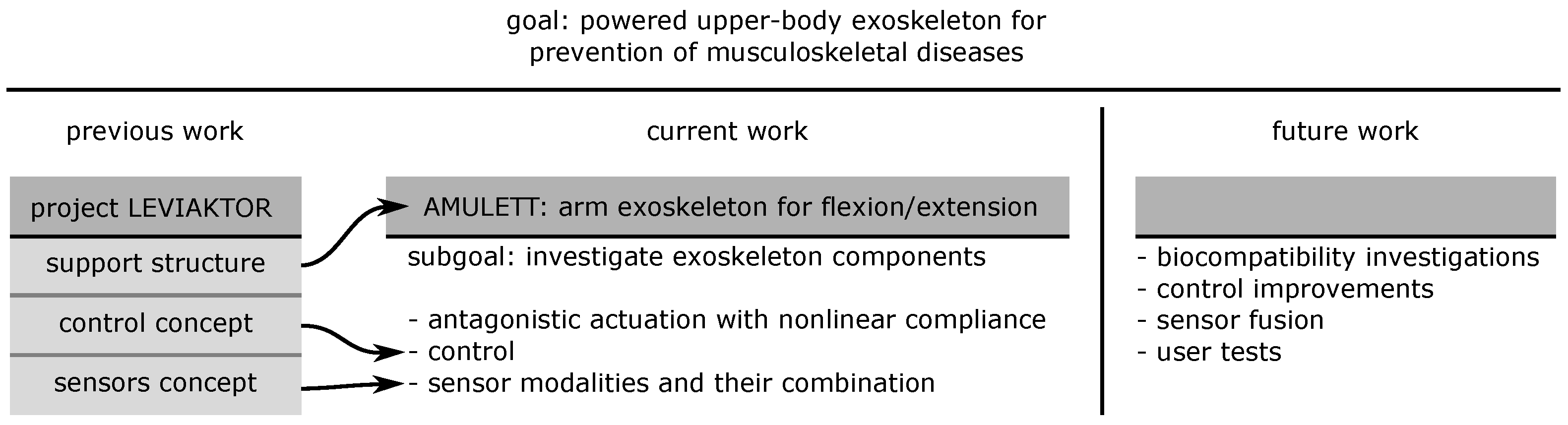
The general goal of our research, based on the results of project LEVIAKTOR (“LEVItation mittels AKTorik in ORthesen”; English: levitation via actuators in orthoses, BMBF 16SV8004), is to develop a powered upper-body exoskeleton for application in, e.g., industry and healthcare (
Figure 1). We aim to prevent musculoskeletal diseases by a reduction of the peak loads on the user, which leads to an average load level with minor fluctuations, and thus could delay the occurrence of fatigue [
1]. Functional replacement or augmentation is not the goal of our work, only the support of existing functions.
Here, we looked in detail at components of the actuation system to increase the biocompatibility of the whole system, especially with regard to interaction forces and torques arising between the technical and biological systems, as well as energetic effects and the smoothness of the system’s kinematics. To reduce the complexity of the analysed system, we focused on the active support of flexion and extension in an artificial “elbow joint”.
Interactions between human beings and robots benefit considerably from the compliant behavior of both contact partners to reduce the risk of injury [
2,
3], and improve mechanical and control robustness [
4,
5,
6]. This particularly applies to exoskeletons that are in constant physical contact with the user. Examples for upper-limb exoskeletons with defined compliant elements are given in [
7,
8]. Koganezawa et al. elaborated on the principles for the control of joints by using actuators with nonlinear compliance, taking the human wrist joint as a paragon [
9]. They illustrated that compliant elements could be used to vary the joint stiffness dynamically by tensioning of the actuators against each other. Following the biological paragon, therefore, two opposing actuators are required to move the same joint in an (in the terminology of functional anatomy) antagonistic fashion. Furthermore, based on observations of the mechanical properties of muscle–tendon systems [
10], the compliant elements need to have a nonlinear spring characteristic to provide defined and reproducible operating points and to allow a variation of the joint stiffness [
11,
12,
13], as has already been argued [
9]. Compliant antagonistic actuators provide energetic potential fields, whether their spring characteristics are linear or nonlinear. Nonlinear spring characteristics allow for a “soft” guidance of masses through the potential field. Close to the desired trajectory, the resistance against perturbations is lower than with linear spring characteristics. In contrast, the movement is confronted with steeper potential “walls” for larger disturbances.
Figure 2 gives a visualisation of a cut through the potential field, forming a “potential channel”. The biological paragon is described in [
14] for quadruped locomotion but can also be transferred to single joints.
Figure 2 also shows how the energetic potential field may be shaped by a coordinated change of antagonistically acting nonlinear springs, e.g., by a variation of the steepness of their characteristic curves, offset or preload.
In
Appendix A, the concept of [
9] is detailed by illustrations of how to define operating points and spring characteristics for antagonistically acting compliant actuators.
Motion guided by fields of potential energy such as in the ballistic movements of human limbs [
15] and its control [
16] may provide the base for biocompatible technical motion control, e.g., for the interaction of the arm and exoskeleton examined here. The characteristics of those curves for the combinations of nonlinear antagonistic springs open the perspective to design the
Hamiltonian function: with the help of the
Hamiltonian function, the optimization of the control parameters in an “application-friendly” manner by providing “slack” (flat) regions in the potential field for applications with lower demands concerning precision can be performed. Thus, the use of microcontrollers can be facilitated for local joint control. However, before starting this development, it has to be checked whether the embodiment of an exoskeleton element in the real world with all—not yet calculable—side effects mirror the predicted model-based kinematic behavior. Therefore, in this contribution, we focused on the testing of hypotheses concerning the kinematic behavior of the embodiment of a representative component of an exoskeleton. This qualification is supposed to form the base for the realization of new control concepts in future contributions.
1.1. Hypotheses
Analysing the predictions which could be derived from simulations, with regard to the application we aim at, we define the following hypotheses to check crucial points of the concept:
Nonlinear compliance may serve to limit the peak net torque and thus the peak power occurring in a joint.
Nonlinear compliance may prevent the control system from provoking an “overshoot” in the angular motion of the joint.
Peak angular velocity, angular acceleration and angular jerk of the joint will be reduced using compliant actuation.
Latencies due to compliant actuation may be kept within acceptable ranges.
1.2. Nonlinear Spring Characteristic Through Mechanisms
During the design process of a modular upper-extremity exoskeleton, we tried to apply the basic principles described in [
9] to the embodiment we aimed for. Therefore, among other things, nonlinear spring characteristics were needed to fully utilize the benefits of a compliant actuation. One method to realize this is the use of “virtual springs” through the control of the actuator’s dynamic behavior [
17,
18]. Common to all “virtual spring” solutions is the missing recuperation of energy: the dissipation of energy is actively compensated by the work of the actuators. Those energetically inefficient solutions with the primary goal to provide short reaction times are beyond the scope of our work. Energetic efficiency is one of the main reasons to choose compliant mechanisms in exoskeletons (
Section 2.1). The main nonvirtual approach described in the literature to achieve the necessary nonlinear spring behavior is to transform linear spring characteristics into nonlinear ones through mechanisms. The following solutions have been described:
We decided to implement a mechanism using linear tension springs acting on a movable pulley, as described in [
26]. The nonlinear characteristic is a result of the angle at which the spring acts on the pull cable. This angle depends on the deflection of the spring; thus, the mechanism shows a stiffening behavior (see
Section 2.1).
1.3. Our Contribution
For our experiments, we used an observation object with only one lightweight movable segment in a two-bar gear line, with kinematics comparable to those of the human elbow joint (upper arm–joint function reduced to one rotational degree of freedom–lower arm). Both the actuation system and the compliant elements were separated from the movable segment to isolate the dynamic behavior of the components from one another and to reduce the mass moment of inertia, following the principle described for vertebrates’ extremities [
27]. This setup allowed us to reproduce the behavior of a component of an upper extremity exoskeleton under gravity, with the flexor “muscle” acting against gravity, while the extensor “muscle” was supported by it. We thus introduce the current iteration of AMULETT (Active MUscle-controlled Lightweight ExoskeleTon Testbed), an arm exoskeleton experimental platform, here with a spatially fixed “upper arm” (
Figure 3).
We compared biologically inspired antagonistic compliant actuators with different actuator configurations:
Isolated unilateral stiff;
Isolated unilateral compliant, both with just gravity and inertia acting antagonistically without an antagonistic drive;
Antagonistic stiff.
To test our hypotheses stated in
Section 1.1, we investigated the system’s behavior during flexion and extension movements regarding:
The variation of the joint stiffness by tensioning antagonistic compliant actuators against one another;
The overshoot amplitude and time to reach the target position;
The maximum angular velocity, angular acceleration and angular jerk during flexion;
The force at maximum angular acceleration during flexion.
2. Materials and Methods
The terminology used for the description of the actuator functions in this contribution is based on that of the biological paragon for musculoskeletal systems in vertebrates, following the
Terminologia Anatomica in its 1988 version [
28], mirrored by its use in everyday English language.
2.1. Exoskeleton Test Bed AMULETT
AMULETT is a test bed for arm exoskeleton components, which is antagonistically actuated in an anthropomimetic way, to support the flexion and extension of the elbow. Since we excluded augmentation or amplification as application purposes, we were able to use lightweight and low-cost components, especially actuators. The modularity of the design allows the exoskeleton to be adapted to different users and use cases [
1].
2.1.1. Structure
In the current iteration, the support structure of the modular AMULETT consists of 3D printed parts to reduce weight and costs and to increase the adaptability of the system: one supporting beam each for the upper and forearm can be connected to the user’s arm via cuffs. Here, the cuffs are tightened to the dummy arm (
Figure 3) with hook-and-loop straps. The exoskeleton’s technical elbow joint is implemented by a ball bearing to reduce friction and transverse reaction forces occurring from the constraints of the natural elbow joint. Two opposing (hereafter “antagonistic”) strings originating from the actuation assembly, passing the upper arm and the elbow joint, attach to the forearm’s supporting beam to allow flexion and extension in the elbow joint(s). In the full system, the actuator assembly is intended to be mounted on the user’s back to reduce the weight of the exoskeleton on the arm and thus to reduce inertia (
Figure 4). The antagonistic actuator assembly with proximalized masses follows the paragon of the human arm [
6,
27,
29]. Therefore, in the following, the two actuators will be referred to—in an abbreviated form—as “biceps” for the flexion-supporting actuator (corresponding to
M. biceps brachii) and “triceps” for the extension-supporting actuator (corresponding to
M. triceps brachii).
2.1.2. Antagonistic Compliant Actuation
In the type of antagonistic actuation we used, both antagonistic motors logically move their transmissions in opposite directions. In a
rigid antagonistic system, control deviations or disturbances in motor coupling can lead to high transient peak forces between actuator and exoskeleton support structure, possibly damaging the components involved. As we used strings to transmit forces from the actuators to the exoskeleton support structure, these errors may lead to the situation where the string on the nonpulling side falls slack due to losing a load. This effect increases undesired play in the system. The phase of the subsequent reloading of the slack string provokes rapid, possibly destructive changes in the motor load. Thus, antagonistic actuators preferably should have compliant transmission elements between them [
6]. With such
compliant transmission systems, the distances travelled by the antagonistic actuators do not necessarily have to be equal. In order to minimize the parameters to be observed for an identification of the main characteristics, the arrangement of the two sides of our experimental setup was designed symmetrically, with respect to both the spring characteristics and the mechanism (
Appendix A). Thus, the characteristic curve of the rotational compliance around the joint was also symmetrical with respect to the defined local minimum.
Due to three main reasons identified in the analysis of vertebrate muscle–tendon systems (see [
30,
31]), we selected compliant elements with nonlinear spring characteristics, as described in [
9] for AMULETT. First, in contrast to linear spring systems, nonlinear springs tensioned against one another provide a lower resistance under small loads than with larger loads, offering the opportunity of “kinematic inaccuracy” with wider stability zones in the neutral zone, where they are under no or only small loads, minimizing the control effort (
Section 1). Second, with a progressive characteristic, if the neutral zone is left more on one or the other side, the energy to be invested in elastic storage increases with more than the square of the deflection (as with linear elastic springs). Due to the rapidly increasing steepness of potential fields, the motion is limited by built-in energy-absorbing effects, which may recuperate the energy to the countermovement and form virtual “stability walls”. Third, the inclination of the characteristic is different at each of its points, and thus allows its determination by small perturbations (
Figure 2).
Using this spring characteristic in our antagonistic actuation allows us to change the overall joint stiffness by tensioning the drives against each other as described in [
9] and corresponding to the biological model [
12,
13]. Due to its biological inspiration, it should facilitate a more biocompatible mechanical interaction with the user of the exoskeleton, especially due to lower undesired interaction forces.
Adjusting the joint stiffness during motion allows a reduction of the energy demand and enables switching between high accelerations at the beginning of motion and improved positioning accuracy at the end of motion [
12,
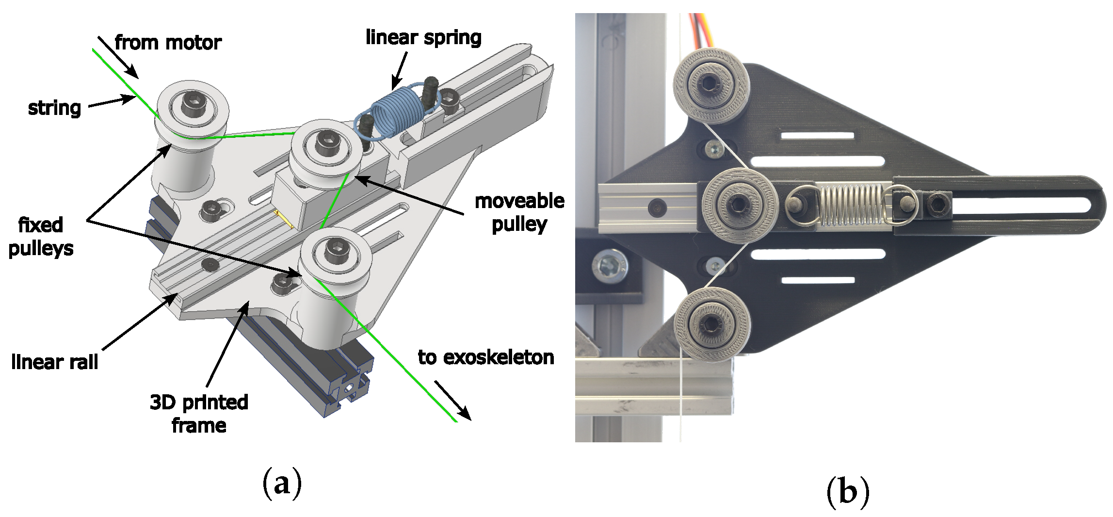
32]. The nonlinear characteristic was achieved by a linear tension spring on a movable pulley as described in [
26] (
Figure 5). This setup, in the following referred to as “NonLinear Spring” (NLS), was used in both biceps and triceps strings. The force needed to deflect the NLS can be calculated using Equations (
1)–(
4) and
Figure 6a. The resulting spring characteristic is shown in
Figure 6b.
| NLS deflection force |
| Deflection of the linear tension spring |
| Spring rate of the linear spring |
| Angles, see Figure 6 |
| a | Vertical distance between fixed and movable pulleys |
| Horizontal distance between fixed and movable pulleys when the NLS is not deflected |
| r | Radius of the pulleys |
Figure 5.
Assembly to achieve the nonlinear spring characteristic, following [
26]. (
a) CAD rendering of the NonLinear Spring (NLS) assembly. (
b) The NLS assembly in the experimental setup.
Figure 5.
Assembly to achieve the nonlinear spring characteristic, following [
26]. (
a) CAD rendering of the NonLinear Spring (NLS) assembly. (
b) The NLS assembly in the experimental setup.
Figure 6.
(
a) Sketch of the NonLinear Spring (NLS) assembly. The dotted circle marks the position of the movable pulley with no deflection of the tension spring. With
—NLS deflection force,
—deflection of the linear tension spring,
—spring rate of the linear spring,
—angles,
a—vertical distance between fixed and movable pulleys,
—horizontal distance between fixed and movable pulleys when the tension spring is not deflected and
r—radius of all pulleys. (
b) Spring characteristic of the NLS, calculated with Equations (
1)–(
4) and
= 0.962 N/mm (spring: RZ-104I; Gutekunst + Co.KG, Metzingen, Germany),
a = 40 mm,
h0 = 18 mm,
r = 10 mm.
In our experimental setup, the following parameters were used: 0.962 N/mm (spring: RZ-104I; Gutekunst + Co.KG, Metzingen, Germany), 40 mm, 18 mm and 10 mm.
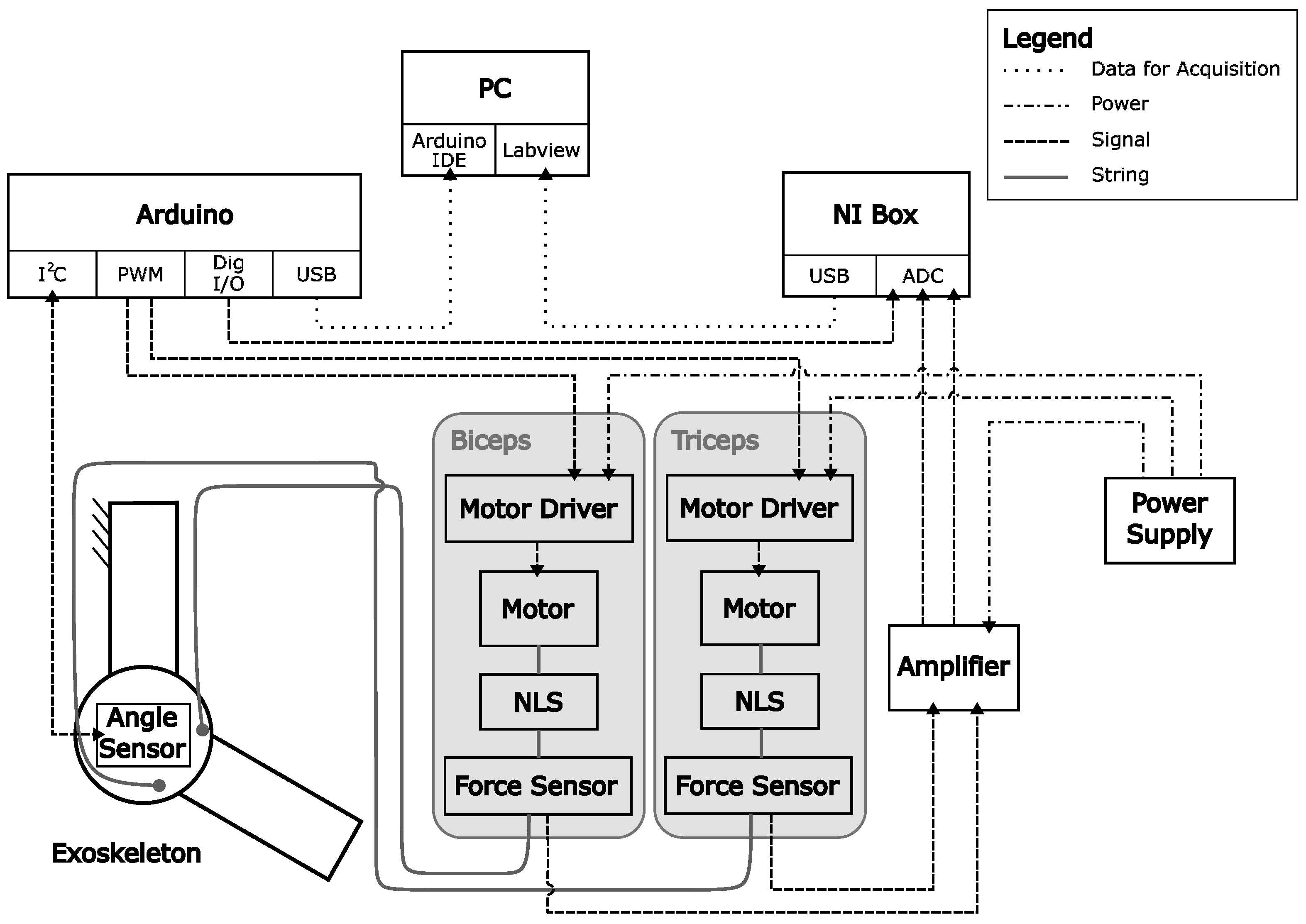
2.2. Experimental Setup
Figure 7 shows the schematic of the experimental setup. In order to improve the repeatability of the measurements, a “dummy arm” was attached to the support structure of AMULETT for the conducted experiments. This dummy arm consisted of an additional, similar support structure with a longer forearm-supporting beam, and without actuator connection (
Figure 3). 3D printed parts were used as the interface between the exoskeleton support structure and the dummy arm, which were designed to fit the shape of the cuffs of the exoskeleton. The dummy arm was attached to a frame consisting of bolted-together aluminium extrusions. The main purpose of the frame was the suspended support of the actuator assembly to avoid lateral forces on the force sensors located in the biceps and triceps strings. The actuator assembly consisted of two stepper motors (ST4118D3004-A; Nanotec
® Electronic GmbH & Co. KG, Feldkirchen, Germany), each with a 3D printed two-stage spur gear (gear ratio: 15.555:1). Two motor drivers (DM542; settings: 4 microsteps, current limited to 1 A peak; ACT MOTOR) controlled the stepper motors. Biceps and triceps strings ran from the respective pulleys on the last gear of each gearbox through the nonlinear springs via pulleys to the exoskeleton. Weights were attached to the dummy arm to achieve a weight distribution comparable to that of the human arm (see
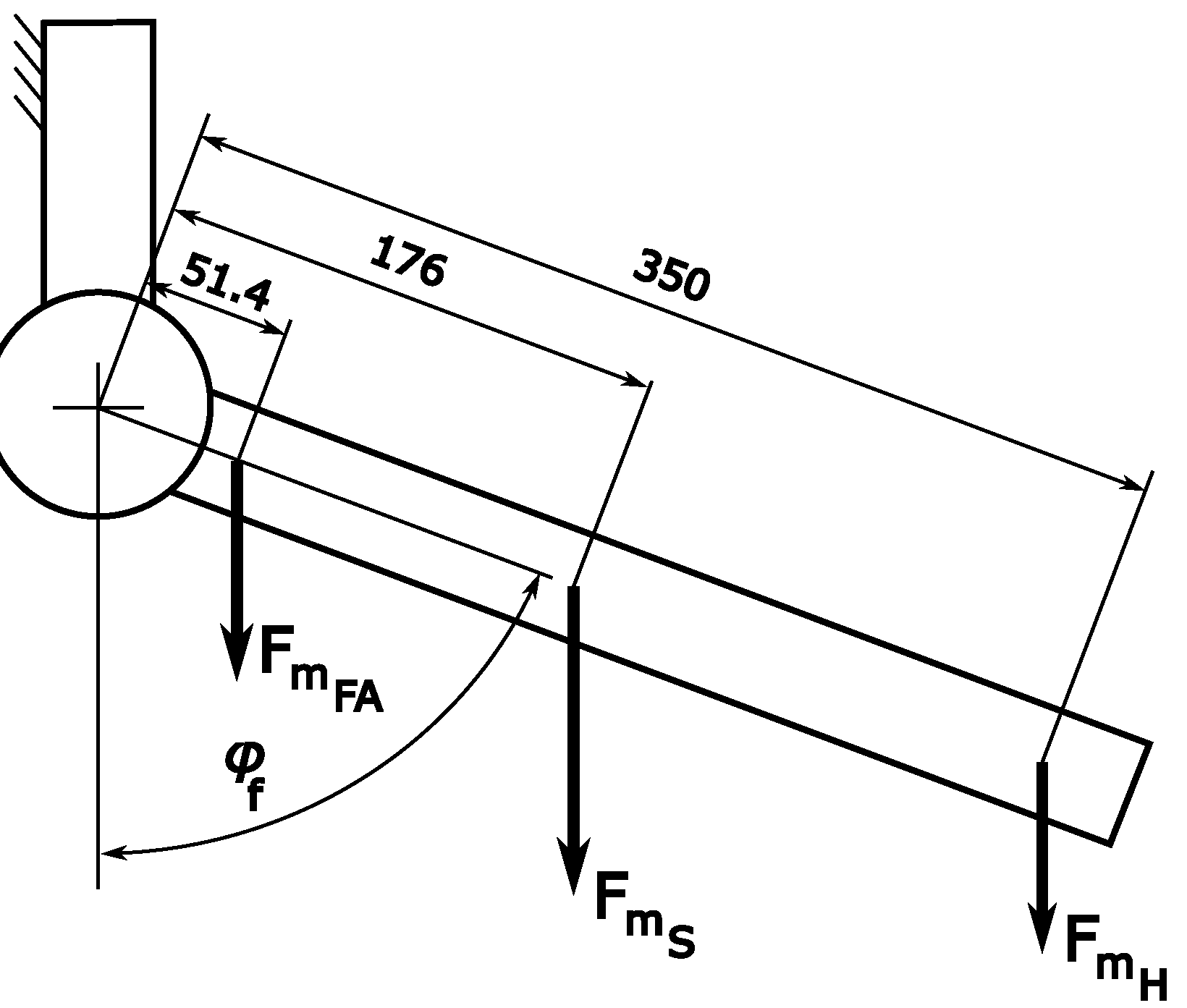
Figure 8). To choose stepper motors of appropriate torque, we assumed a weight distribution that would lead to the maximum required torque for the actuation, according to the literature regarding anthropometric forearm and hand data [
33,
34,
35,
36,
37]. A forearm with length 310 mm [
34] and weight 1.52 kg was assumed, with the center of mass at 133 mm from the elbow joint [
33]. The center of mass of the hand was assumed to be at 239 mm from the elbow joint [
33,
35,
37], with a weight of 0.48 kg [
33]. The masses for the dummy arm were scaled down by a factor of 0.15 compared to the biological masses in order not to overload the 3D printed construction or the force sensors:
A weight of 100 g at 51.4 mm distance to the elbow joint. Combined with the weight of the forearm supporting beam (110 g, center of mass at 176 mm from the elbow joint), this resulted in the center of gravity of the dummy arm being comparable to that of the biological forearm.
An additional weight at 350 mm distance to the elbow joint. The mass was varied between experiments to simulate different loading situations of the hand.
Figure 4 shows the experimental setup in its entirety.
2.2.1. Sensors and Data acquisition
To characterize the dynamic behavior of the experimental setup, the following sensors were used (see
Figure 7). An angle sensor (Hall effect sensor with magnet; AS5048B; ams-OSRAM AG, Premstaetten, Austria) was attached to the elbow joint of the exoskeleton to measure the flexion angle of the forearm supporting beam (
Figure 4). The sensor was connected to a microcontroller (Arduino Mega 2560; Arduino) via I
C. One strain gauge force sensor (F250 UFR0H0; rated load 100 N; Novatech Measurements Limited, St Leonards on Sea, UK) was mounted on each string to measure the string forces. The force sensor signals were amplified (amplifier: SG-2K-KS; Althen GmbH Mess- und Sensortechnik, Kelkheim, Germany) and transmitted to NI LabVIEW via an NI data acquisition box (NI USB 6008; sampling rate 1 kHz; National Instruments, Austin, Texas, USA). The NI DAQ box was connected to a digital pin of the microcontroller to synchronize data by means of a square-wave signal. The force sensor signals and the square-wave signal were stored on the PC. The measurement data of string forces were used to assess the influence of compliant elements. They were not intended to supplement the exoskeleton control. The microcontroller was also used for data acquisition (sampling rate set to 100 Hz). The following data were transmitted from the Arduino to the PC and collected via the Arduino IDE:
The time stamp;
Square-wave signal for synchronization with LabVIEW data;
The angles of the pulleys of the two drives, calculated from the motor positions and transmission ratio;
The exoskeleton flexion angle as measured by the Hall effect sensor;
The target value for the flexion angle.
After the acquisition, the data from the Arduino and force sensors were synchronized and processed offline by Python scripts (
Section 2.4). Force sensors were calibrated before starting the experiments described below.
2.2.2. Control
The Arduino microcontroller controlled the stepper motors of the exoskeleton using the motor drivers. We implemented a PID position controller on the Arduino microcontroller. The PID parameters were optimized for the
antagonistic stiff configuration (
Section 2.3) following the methods introduced in principle by
Ziegler and Nichols ([
38] and following papers) to be
,
and
. These parameters were used with all configurations to achieve a better comparability of the results. The signal of the angle sensor in the elbow joint of the exoskeleton served as the feedback source. The output of the controller was used directly to position the biceps drive. For the position of the triceps drive, two independent offsets were calculated: To maintain string tension, the difference between the angle of the biceps pulley and the flexion angle of the exoskeleton was determined as the first offset. To ensure the preload, an additional offset was used, which depended on the control deviation and was calculated according to Equations (
5) and (
6). Both offsets were added to the output of the position controller to set the triceps drive’s position. A fourth-order function was selected for the second offset in order to ensure a high steepness.
| Offset (°) |
| s | Scaling factor, depending on the selected preload setting |
| Target position (°) |
| Actual position (flexion angle of the exoskeleton) (°) |
| Angular difference between target and actual position at which the offset is increased (constant) (°) |
| Selected preload (°) |
| Minimum preload (constant) (°) |
Thus, in the case of the
antagonistic compliant actuator assembly configuration, the joint stiffness was further increased shortly before the exoskeleton arm reached the target position. The additional tensioning of the antagonist before reaching the target position follows the biological model [
12,
13]. The preload was realized by an angular offset. For example, at
= 20°, the biceps drive moved −20°, the triceps drive +20°, in addition to the position specified by the controller. This caused the biceps and triceps to be tensioned against one another.
2.3. Experiments
To investigate the behavior of the nonlinear springs and their interaction with the control of the complete system, the following measurements were performed:
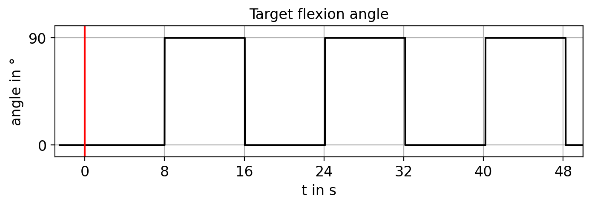
The target flexion angle for position control was set from 0° to 90° and from 90° to 0° as a rectangular function with period 16 s (
Figure 9). Angles and forces measured thus corresponded to the step response of the system. The period was chosen to allow all system configurations to reach the target angle stably. Flexion and extension motions were repeated ten times for each measurement.
This procedure (
Figure 10) was realized with different configurations of the setup:
Configuration of the actuator assembly:
| unilateral stiff: | only biceps motor | without NLS |
| unilateral compliant: | only biceps motor | with NLS |
| antagonistic stiff: | both motors | without NLS |
| antagonistic compliant: | both motors | with NLS |
Mass at hand position: (50, 100, 150, 200) g;
Preload achieved by = (0/5, 10, 20, 30)°.
An overview of the measurements conducted can be found in
Appendix B in
Table A1. For the antagonistic configurations of the drive assembly, no measurements were taken with
= 0°, since this value would lead to slack in the triceps string. Force measurement would not be useful this way, so instead,
= 5° was chosen for these configurations. This ensured tension of the string without a noticeable deflection of the tension springs of the NLS for the
antagonistic compliant configurations. For simplicity, this setting is also labelled “0°” in the plots. For the measurements, the constants in Equation (
5) were set according to
Table A1 in the appendix.
To remove the compliance of the NLS from the system, the strings were disengaged from the pulleys of the NLS. To achieve the unilateral actuation system, the last gear of the triceps transmission was removed from the gear box. With the
antagonistic stiff configuration, the system was still sufficiently compliant to work nondestructively (
Section 2.1), since the structure was inherently flexible, even without dedicated compliant elements.
To investigate the adjustable joint stiffness, the forearm-supporting beam of the exoskeleton was deflected manually by approximately 30° and allowed to oscillate with the preload set and the PID controller turned off. During this process, the flexion angle signal was recorded. This experiment was performed for the antagonistic compliant system with = (5, 10, 20, 30)° and for the antagonistic stiff system only with = 5°.
2.4. Data Evaluation
The processing steps for the data evaluation are described below. The Python scripts used and measurement data acquired can be requested from the authors.
2.4.1. Force Data
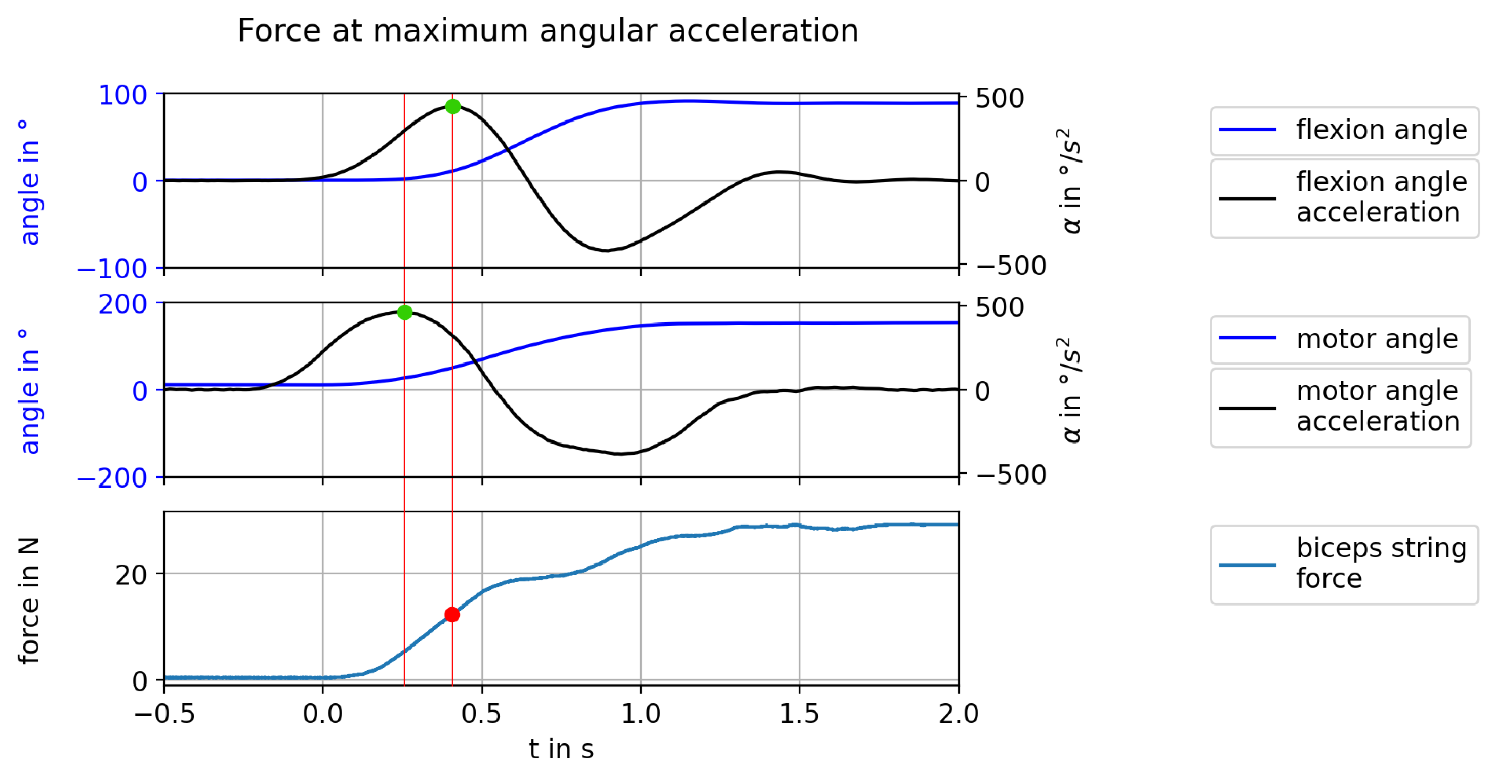
Due to the orientation of the exoskeleton arm, weight forces acted on the structure with a factor
, where
l is the respective distance of the weight from the joint. Therefore, to compare forces between different configurations, only the local maximum of the force in the time window between the maximum biceps drive acceleration and the exoskeleton’s maximum angular acceleration during flexion motion was considered (
Figure 11). For this purpose, the angular signals were interpolated and averaged (moving average,
) before the two numerical differentiation steps to obtain angular acceleration values. In the described time window, the maximum of the averaged biceps force signal (moving average,
) was determined. The lengths of the moving average filters were chosen so that the peak detection algorithm required to find the maximum values performed consistently on all measurement data.
2.4.2. Jerk
To obtain the jerk signal, the acceleration data of the exoskeleton’s flexion angle were averaged (moving average, ) and differentiated an additional time. As stated above, the length of the moving average filter was chosen so that the peak detection algorithm required to find the maximum values performed consistently on all measurement data. For the comparison between configurations, the maximum of the exoskeleton jerk during flexion motion was determined.
2.4.3. Rise Time
The rise time, i.e., the time difference between setting and reaching the target position, provides information about the inertia of the system when changing the actuator assembly configuration or load. For this purpose, the time difference between the rising edge of the target position signal and the time when the deviation between the target position and the actual flexion angle last exceeded 2° was determined. The threshold of 2° was chosen based on human perception thresholds for angle discrimination in the elbow joint [
39].
3. Results
In the following, the results of the experiments described in
Section 2.3 are presented. Due to limitations (
Section 4), only relative, qualitative statements are made from the conducted investigations.
3.1. Variable Joint Stiffness
The experiment described in
Section 2.3 was performed five times each for the configurations
antagonistic compliant with
= (5, 20, 30)° and
antagonistic stiff with
= 5°.
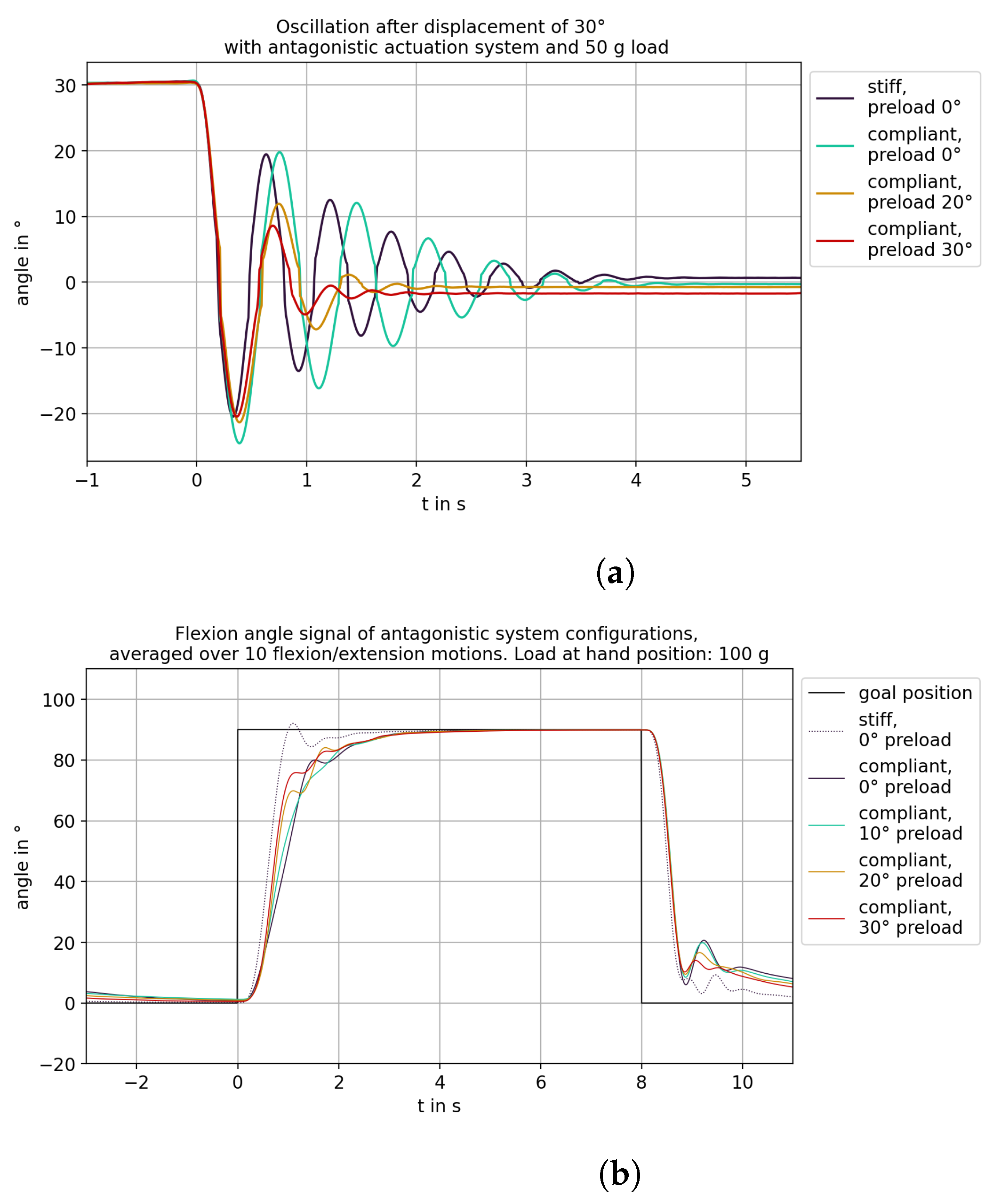
Figure 12a shows the averaged angular trajectories of the five oscillations. Increasing the preload visibly increased the damping of the oscillations. However, a higher preload also led to increased friction in the system, which meant that
= 0° was not reached again at the end of oscillation. The
antagonistic stiff system with a bypassed NLS also exhibited compliance, which is why the amplitude and duration of the oscillation were only slightly lower than with the NLS at
= 5°. However, the arm remained at a higher offset with the
antagonistic stiff system than with the NLS at the same preload. In the plot of the averaged angle signals in
Figure 12b, it can be seen that the increase in preload led to a steeper increase in the angle during flexion motion. The
antagonistic stiff system showed the steepest increase but also overshot the target position.
3.2. Reduction of Force Peaks
Force data were obtained according to
Section 2.4. In
Figure 13a, it becomes visible that the addition of compliant elements to the actuation system led to a reduction of the force at the maximum angular acceleration for both unilateral and antagonistic actuation systems. At certain loads, the actuator system appeared to exhibit resonance (
Section 3.3), leading to an inaccurate force determination. This was likely the cause of the significantly increased forces and larger variance for the
unilateral stiff system with a load of 100 g and the
antagonistic compliant system with a load of 200 g. Due to the antagonistically acting drive, the required biceps force was visibly increased for the antagonistic actuation compared to the unilateral actuation. However, the increase was much smaller in the case of actuation with compliant elements. In
Figure 13b, the force corresponding to
Section 2.4 is shown for the
antagonistic compliant system at different preloads. Force in the biceps string increased with preload and also exceeded the values of the
antagonistic stiff system at
= 20° and above. The force offset due to the preload additionally increased the occurring force but could not be simply subtracted, since the preload changed during movement as a result of the two offsets described in
Section 2.2.
3.3. Reduction of Overshoot
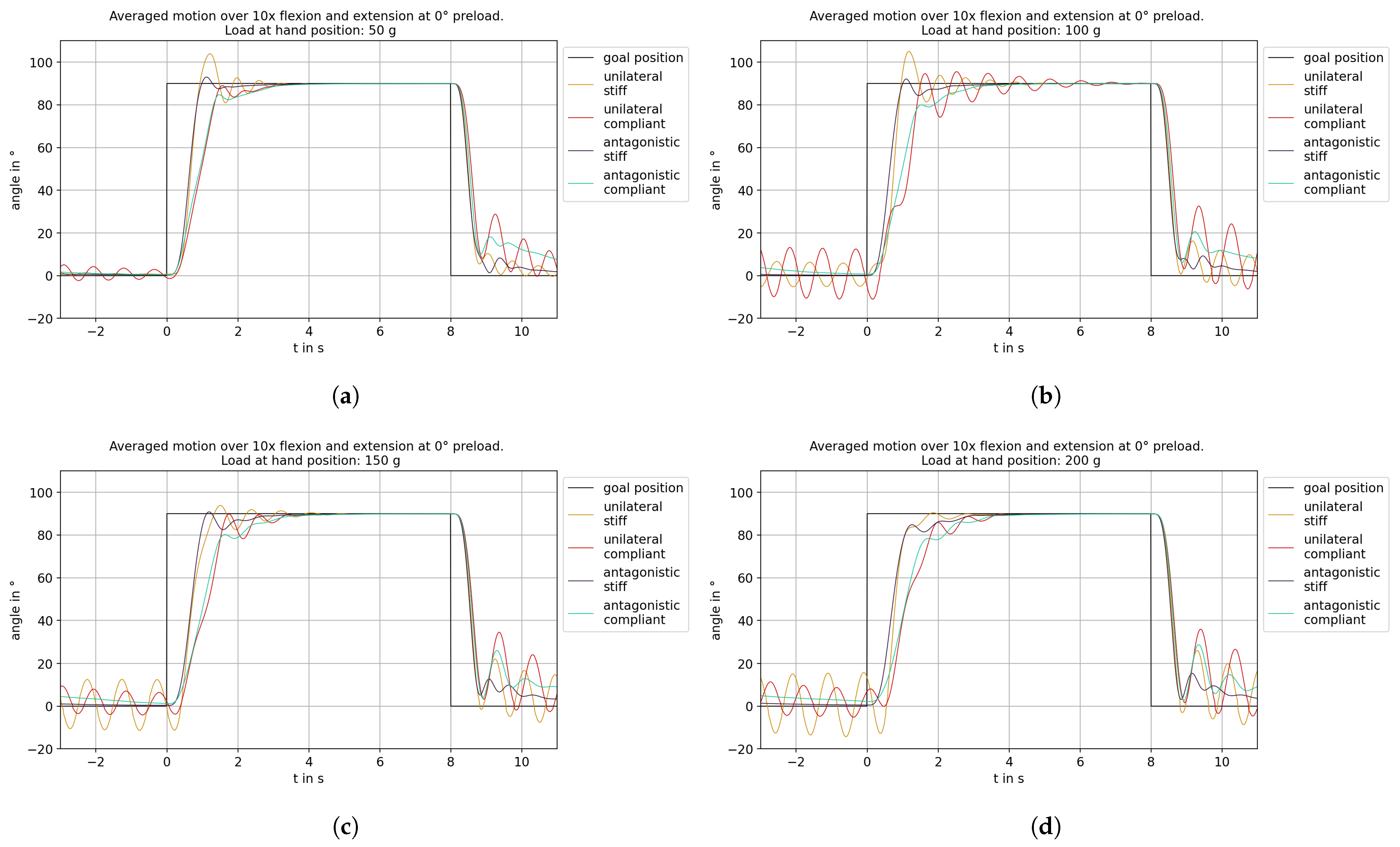
To compare the influence of the actuator configuration on the angular response, the ten flexion/extension motions were extracted from the data of the measurements with
= 0° and 5°, respectively, and averaged (
Figure 14). Compared to
antagonistic stiff configurations, the
antagonistic compliant system exhibited larger damping. The increase in angle was reduced by an increased damping compared to stiff configurations. Increasing the load further dampened the system. The tightening of the triceps drive at
= 80° with the
antagonistic compliant system was clearly visible as well (
Section 2.2).
Both unilateral configurations tended to oscillate significantly more than the antagonistic configurations. In particular, both configurations oscillated strongly during extension, though an amplification effect due to the position controller could not be ruled out.
Both compliant configurations exhibited a reduced overshoot compared to the stiff systems: Up to a load of 150 g, stiff systems overshot the target angle of = 90° during flexion, in contrast to the compliant ones. At a load of 100 g, the system appeared to exhibit resonance, with both unilateral configurations overshooting significantly more and resonating longer than at the other loads. A similar behavior occurred for the antagonistic compliant system with a 200 g load. The system appeared to be considerably more likely to oscillate around = 0° in this configuration than at lower loads.
3.4. Rise Time and Angular Velocity
To assess the rise time, the time difference between setting and reaching the target position during flexion was considered. As one would expect, the increase in load and the additional compliant elements led to an increase in the time difference (
Figure 15a). Comparing
unilateral stiff and
antagonistic stiff systems, the antagonistic drive caused a decrease in time difference, because it reduced the overshoot of the system. The
antagonistic compliant system showed higher time differences than the
antagonistic stiff system but comparable to the
unilateral compliant system. As can be seen in
Figure 16, the increase in rise time with the addition of an antagonistic drive stemmed from the lower angular velocity
during flexion motion. The angular velocity was comparable to that of the
unilateral compliant configuration but did not exhibit the oscillations mentioned in
Section 3.3.
Figure 15b shows the time differences for the
antagonistic compliant system with different preloads. Theoretically, increasing the preload should lead to a stiffening of the system and thus to a decrease in the time difference. However, this was not the case; as the preload increased, the time difference also increased. Increasing the load also resulted in a reduction in the time difference. For a 100 g load, this behavior was masked by the resonant behavior (
Section 3.3). For a 200 g load, the system exhibited similar time differences for all four preloads.
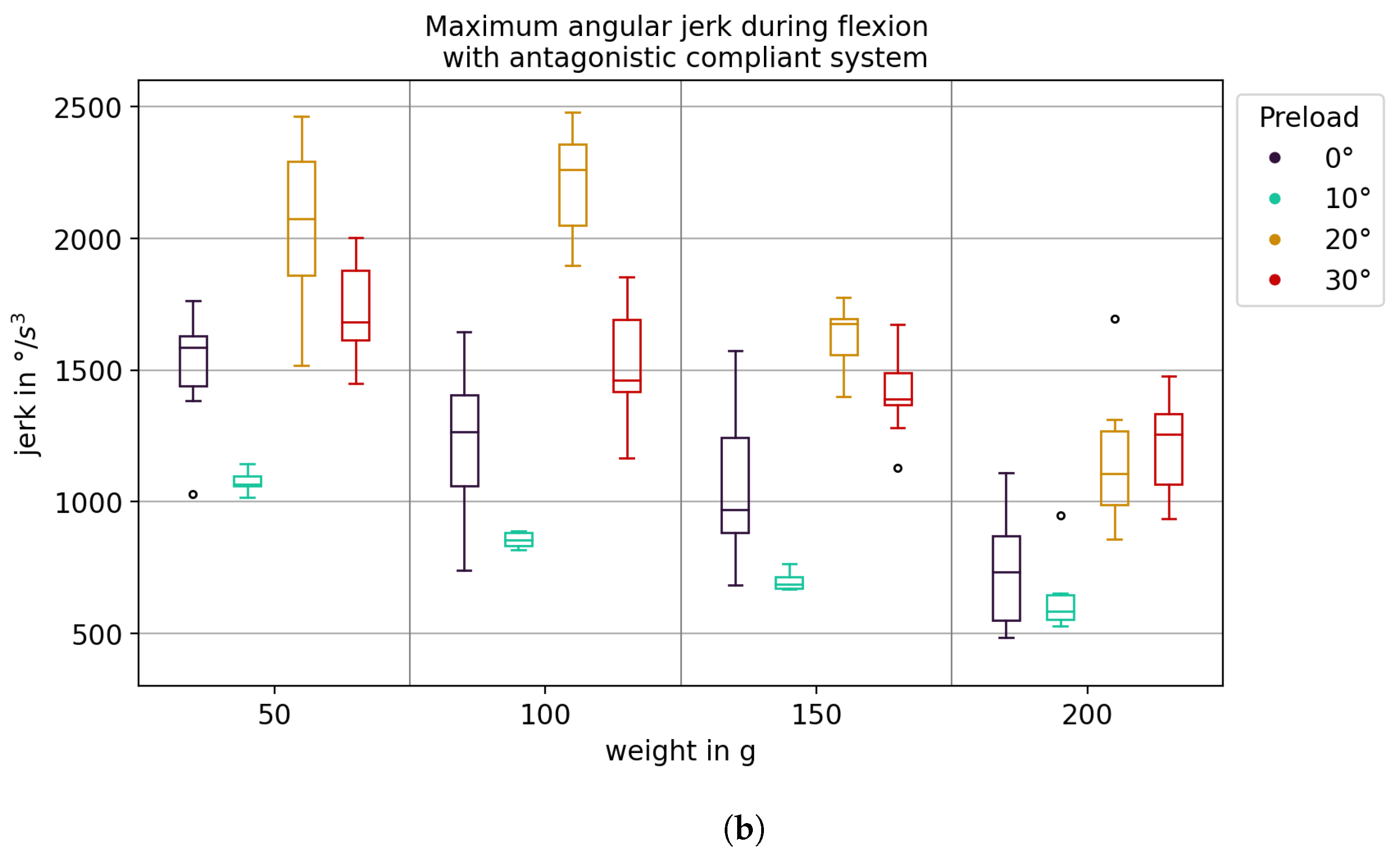
3.5. Reduction of Jerk
Figure 17a shows the maximum angular jerk during flexion motion for different actuator configurations. The
antagonistic compliant system exhibited the lowest maximum angular jerk for all loads. In particular, for the
unilateral compliant system, the previously mentioned resonance at a 100 g load was visible as a significant increase in angular jerk. It may also be seen that for unilateral systems, the maximum angular jerk increased with the load, while for antagonistic systems, it decreased. In
Figure 17b, the maximum angular jerk is shown for the
antagonistic compliant system at different preloads. No simple relationship between preload and maximum angular jerk was apparent. However, for all four preloads, the maximum angular jerk decreased as the load increased. For
= 10°, the variance of the maximum angular jerk was much smaller than for the other preloads.
4. Discussion
We present an experimental setup to investigate an
antagonistic compliant actuation beyond simulation, using exoskeleton components for our experimental setup, called AMULETT. Comparison to
unilateral stiff,
unilateral compliant and
antagonistic stiff actuation points to the advantages and limitations of the implementation of the
antagonistic compliant actuation presented here. In accordance with our expectations (
Section 1.1) regarding the application of nonlinear compliant elements with antagonistic actuators, the stiffness of the joint could be adjusted by tensioning the two drive components against each other. However, the results of the experiments also showed that increasing the string tension increased friction in the system, thus the exoskeleton arm did not return to the zero position at the end of the oscillation. A similar effect was described by [
40], stemming from increasing the friction inside Bowden cables. Depending on the application, this effect should be compensated by either modifications of the mechanical or the control system. On the other hand, as stated by [
40], the effect increased the resemblance with the biological system, which also exhibits an increased damping when increasing the joint stiffness.
Compared to unilateral actuation, adding an antagonistically acting drive could reduce the oscillatory behavior of the arm, especially during extension. The compliant elements dampened the system, reducing the overshoot (hypothesis 2 in
Section 1.1). However, the damping also led to an increase in rise time, a result of the reduced angular velocity (hypothesis 3 in
Section 1.1). This increase did not exceed 50% with our setup, compared to the
antagonistic stiff actuation (hypothesis 4 in
Section 1.1). However, the increasing rise time of the
antagonistic compliant configuration with an increasing preload needs to be investigated further.
Compliant elements in the antagonistically actuated system reduced the force in the biceps string at maximum angular acceleration. The adjustable stiffness of the system could theoretically reduce rise time, but this leads to an additional force in the biceps string. Increasing the preload leads to a higher force in the biceps string, which increased the energy demand of the actuation system [
6] but would not influence the interaction forces with the user. At the current time, it is not possible for us to isolate the action-dependent force signal from that of the preload force, so the comparison of the force signals between stiff and preloaded compliant antagonistically actuated systems is not possible. However, our findings show that an adjustable joint stiffness, achieved through the
antagonistic compliant actuation, could be used to reduce the peak torque and thus peak forces applied to the user (hypothesis 1 in
Section 1.1).
The maximum angular jerk was reduced as well with the
antagonistic compliant system (hypothesis 3 in
Section 1.1). However, when the preload was changed, no relationship between the preload angle and the maximum angular jerk could be determined. Since the angular jerk was calculated by a threefold differentiation with an averaging of the data before each differentiation step, its determination is likely to be highly inaccurate. Therefore, it is difficult to make accurate statements about the change in angular jerk when the system configuration is changed. We conclude that our findings do not contradict the hypotheses stated in
Section 1.1.
Limitations of Our Approach
The main source of error in our measurements can be attributed to the undesired elasticity of the experimental setup due to the extensive use of 3D printed parts and the hanging setup of the actuation assembly. Sensor noise from force and angle sensors, as quantified in the respective data sheets, can be considered negligible compared to this influence. However, using lightweight 3D printed parts can be expected to reduce inertia, compared to implementations such as in [
20]. To make the investigations similar to our exoskeleton application, the AMULETT’s support structure was positioned “against gravity” with regard to flexion. As a result, force signals primarily showed the influence of the load at the hand position, which, due to longer lever arms, increased with the angle of flexion. For this reason, the force at the time of the greatest angular acceleration was considered as a compromise. However, the determination of the angular acceleration is potentially inaccurate, because it requires the angular signal to be differentiated twice, and a moving average method was applied to the data before each differentiation step (
Section 2.4). Moreover, attaching the exoskeleton to a dummy arm is not optimal for assessing the mechanical behavior of the NLS. For this purpose, the exoskeleton should be bolted directly to the frame as rigidly as possible. The focus of the investigations we carried out was on being close to the application, which is why these limitations were accepted. To increase the comparability of measurements with different configurations of the system, the same setting of the PID controller was used for all measurements. For the
antagonistic compliant system in particular, the controller can be set to be much more “aggressive”, which would especially reduce rise time. However, with these controller settings, the other configurations would overshoot significantly (which strengthens hypothesis 2 in
Section 1.1) or even become unstable, making the comparison impossible. This also points to a damping effect of the compliant elements. In the experiments conducted, the preload of the motors was implemented via an angular offset between the two drives. The actual preload forces present in the strings were not accounted for in setting this preload, since no force measurement in the string is planned for future iterations of the exoskeleton. Setting the preload force the same with a changed system configuration (especially between compliant and stiff and between unilateral and antagonistic) thus proved to be inaccurate with the routines used. The preload was set relative to the zero positions of the motors, which had to be redetermined at the beginning of each measurement and depended on the compliance of the system (caused by the desired compliant elements and inherent, undesired compliance). Therefore, quantitative statements on the change of the occurring forces when varying system parameters were not useful.
In our experiments, we found no contradictions with the literature.
5. Outlook
Based on our findings, the exoskeleton support structure used could be improved with a focus on exoskeleton applications. To achieve a better control over the compliant behavior of the system, its unwanted inherent compliance should be reduced. This leads to mixed constructions of rigid structures and compliant mechanisms with defined properties between them, such as in the vertebrate “blueprint” embodied in the human user of an exoskeleton. The next hypothesis to test is that morphofunctional similarity increases biocompatibility. A reduced inherent compliance would also allow for a better comparison of the subsystems and composed overall systems by mathematical modelling or simulation. For this, the structure should be oriented in order to avoid flexion “against gravity”.
The current control did not allow for a constant force in the triceps string. The system’s inherent compliance led to a loss of tension in the triceps string during flexion, even with the antagonistic stiff configuration (
Figure 18). The offsets described in
Section 2.2 reduced the slack but could be improved to achieve a more even and controlled triceps force. Implementing an additional controller to maintain the string tension would require string tension feedback. Currently, only flexion makes use of the variable joint stiffness. Future versions should implement tensioning of the strings for extension as well. With the compliant elements presented in this work, the joint stiffness can be adjusted. However, flexion under load will deflect the biceps’ NLS further than the triceps’ NLS. This leads to an asymmetric joint stiffness due to the nonlinear characteristic of the compliant elements. For example: at 90° flexion under load, the exoskeleton arm exhibits an increased resistance against extension, but relatively little resistance against further flexion. This behavior could be compensated by an adjustable spring characteristic of the NLS (cp.
Figure 2). We are investigating ways to dynamically adjust the nonlinear spring characteristic.
For tests on real human arms, the systems will be miniaturized. The pulleys that guide the strings to the exoskeleton will be replaced by Bowden cables, to allow the movement of the exoskeleton relative to the actuation assembly.
Additional sensor modalities could be used to improve the system’s behavior. Since the rise time currently depends on the load at the hand position, it is suggested to consider more complex control methods that allow fast movement of the arm with reduced oscillations. In particular, by considering surface electromyography (sEMG) or interaction force signals, estimates can be made about the load to be lifted, from which adjustments to the control can be made. If required, machine learning methods can be used to implement fusing the sensor information, but even “standard” control approaches may be sufficient. The insights gained in the study presented here form the basis for an improvement of the control of compliant drives.
The effect of a mechanical structure parallel to the biological arm that has similar properties in terms of compliance needs to be investigated, especially regarding interaction forces.


