1. Introduction
Research on soft robots has rapidly grown due to their potential to solve problems that cannot be easily solved by traditional rigid robots. Although they are not suitable for applications requiring precise motion control, soft robots have applications in many areas, including assistive devices [
1,
2,
3], rehabilitation [
4,
5], and agriculture [
6]. They also provide innovative ways to perform traditional robot functions, such as locomotion [
7,
8], or grasping [
9,
10,
11,
12].
Soft actuators are the main source of a soft robot’s motion. While many types exist [
13,
14,
15,
16], this paper is focused on origami-inspired soft actuators (OSPA). OSPA combine the advantages of origami (i.e., low material usage leading to low mass and low cost, reduction in the number of parts, and easy scalability) with the advantages of pneumatic actuation (i.e., high power to weight ratio, inherent compliance, and simplicity compared to tendon-driven or hydraulic actuators). Like all pneumatic actuators they have the disadvantage of requiring a source of air pressure (e.g., a vacuum pump to create negative pressure, or a compressor to create positive pressure). It should be noted that pneumatic bellows actuators (e.g., [
17]) share the advantages and disadvantage of OSPA but are not within the scope of this paper since their design is not inspired by origami patterns.
The first OSPA were fabricated by Martinez et al. [
18] by casting elastomer coated paper composites. They fabricated several paper-elastomer OSPA designs, including an extension actuator that lifted a 1 kg mass. The molds were made by 3D printing. Their method has also been adopted by other researchers in [
19,
20]. It is easy to use but is time-consuming due to the number of steps involved and the elastomer curing process. The weakness of the paper-elastomer composites limited the maximum operating pressures used in [
18,
19,
20] to 30 kPa, 20 kPa, and 10 kPa, respectively. Only 50 unloaded pressurization/depressurization cycles were used to test the actuator for fatigue failure in [
18]. No fatigue test results were reported in [
19] or [
20].
OSPAs have also been made by 3D printing. Sane et al. [
21] designed two actuators based on the Muira-ori crease pattern. One was made of polyether block amide on a selective laser sintering (SLS) machine, and the other was made of thermoplastic polyurethane (TPU) on a fused deposition modeling (FDM) printer. Unfortunately, their actuators were not very strong. The fabricated panels of the TPU actuator were significantly warped at a pressure of only 17 kPa, and a maximum pressure of only 34.5 kPa was used with both actuators. They also did not perform any output force or fatigue tests on the actuators. Schmitt et al. [
22] used multi-material 3D printing to prototype two OSPA designed to produce high forces over short displacements. They manufactured two prototypes using an expensive SLS printer (Stratasys Connex 350). The creases were printed using a “rubber-like” elastomer while the panels were printed using a rigid polymer. Their best prototype produced a force of 40 N at a pressure of 24.5 kPa. No tests were performed at higher pressures. The prototype failed after 30 cycles during an unloaded cyclic pressurization/depressurization test. Yi et al. [
23] presented the design, modeling, and testing of a 3D printed OSPA for rotary motion. The pneumatic chambers were fabricated from flexible TPU using a FDM printer. The OSPA produced an 18.5 Nm torque at the max. pressure of 100 kPa. The results of 10,000 cycles unloaded fatigue test (with a 1 Hz, 17 deg. amplitude, sinusoidal trajectory) show only minor changes in the output response.
Design optimization is necessary to get the best performance out of an actuator. The only OSPA design optimization research found in the literature was reported in [
21]. They began by developing a finite element analysis (FEA) model of their OSPA made from TPU. The design optimization objectives were to maximize the actuator’s normalized blocked force and free stroke while constraining the maximum stress predicted by FEA to be less than half of the ultimate tensile strength of TPU. They solved this multi-objective optimization problem using the non-dominated sorting genetic algorithm II included in the modeFRONTIER software package, Ansys and Matlab. They provided no information about the computing resources, or the time required to perform the optimization. More importantly, they did not validate the optimized design experimentally.
In our previous paper [
24], we proposed a rapid and inexpensive OSPA fabrication method. The method uses the thermal forming of a commercially available heat-shrink tube onto a reusable mold. The fabricated OSPA contract by supplying vacuum pressure or extend when a positive pressure is used. Tests performed using six brands of heat-shrink tubing found that only one brand and type of tubing, Qualtek Q2-F4X, sealed properly using our fabrication method. The performance of only one size of OSPA, made from Qualtek Q2-F4X tubing with a 50.8 mm unshrunk diameter, was studied. A nonlinear FEA simulation was developed and used for predicting the OSPA’s blocked force, but not its displacement. Isometric, isobaric, isotonic, and fatigue test results were presented. One cycle of the fatigue test required the OSPA to raise and lower a 0.9 kg payload. The cyclic fatigue test was run for 1000 cycles. At the end of this test no physical defects or degradation in performance were observed.
The paper is organized as follows.
Section 2 presents an overview of our OSPA design and fabrication methods, and
Section 3 describes how these have been recently expanded. More strenuous fatigue tests than used in prior OSPA research are presented in
Section 4. A brief study comparing our prototypes with OSPA developed by other researchers is presented in
Section 5. The development and validation of the design optimization method is presented in
Section 6. Finally, in
Section 7, conclusions and directions for future work are given.
2. OSPA Design and Fabrication Overview
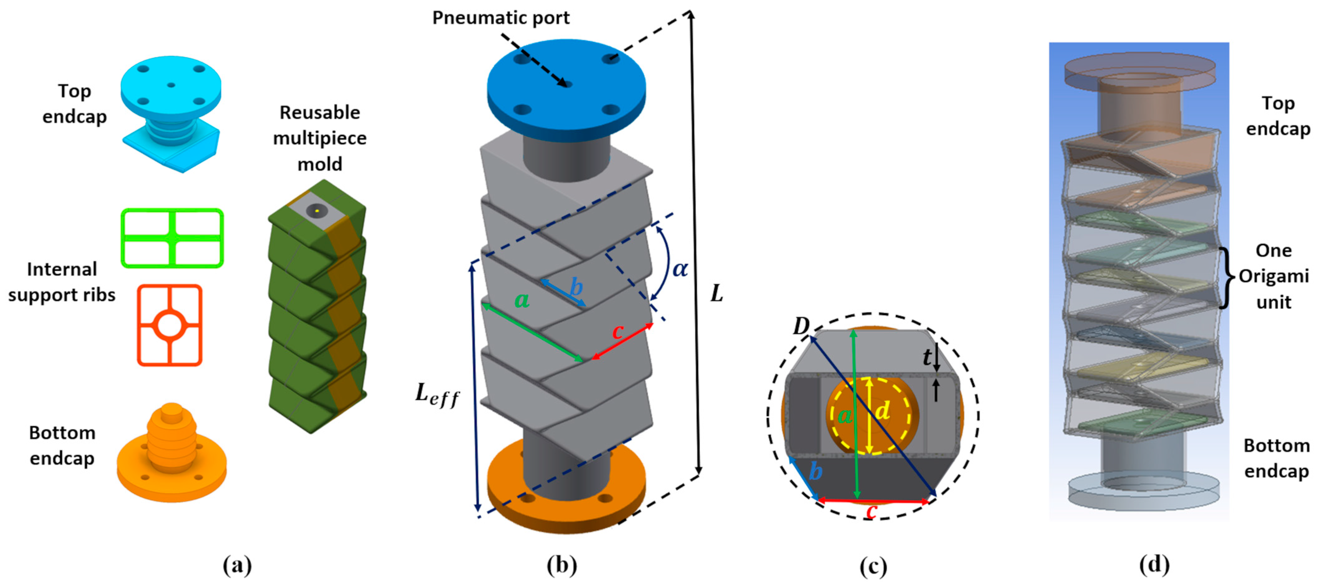
In this section, our OSPA design and fabrication methods will be briefly summarized. Although our fabrication method can be used with a variety of crease patterns, this paper is mainly focused on the conventional accordion crease pattern. The accordion pattern OSPA design is shown in
Figure 1. This OSPA is designed for use with vacuum pressure. Part (a) shows the designs of the rigid top endcap, bottom endcap, internal support ribs, and multipiece mold. The mold is designed such that its pieces are small enough to be safely removed after the flexible body has been formed. The top endcap includes the pneumatic port where the vacuum source is connected. Both endcaps include barbs for improved sealing and mounting flanges. The support ribs help the OSPA to avoid buckling inwards at higher vacuum pressures. They are manually placed into the valley folds inside the actuator, and are held in place by frictional contact with these valley folds. The frictional contact forces are produced by a 10% interference fit between the ribs and actuator’s inner wall. The full actuator and its dimensions are shown in (b) and (c).
L is the total length,
is its effective length, alpha is the initial folding angle (which is the initial dihedral angle between the panels), and
a-d are the panel dimensions. Note that these are chosen such that
. The formed flexible heat-shrink tubing is shown in grey, where
t is its wall thickness. Dimensions
and
D are the bounding inner and outer diameters, respectively. They are useful for scaling the actuator design (as done in
Section 3), and will be employed in
Section 6 to simplify the optimization problem by reducing the number of design parameters. Note that the panel dimensions
a-d can be easily obtained from chosen values of
and
D. Neglecting the wall thickness:
and the accordion crease pattern geometry gives:
As shown in part (d), the active portion of an OSPA consists of several origami units connected in series. The internal ribs are also shown. This OSPA design has four-and-a-half active units since the top endcap occupies half of the uppermost unit. This endcap design has the advantage of properly aligning the top endcap with the actuator’s body, and the disadvantage of reducing the OSPA’s stroke by a half unit.
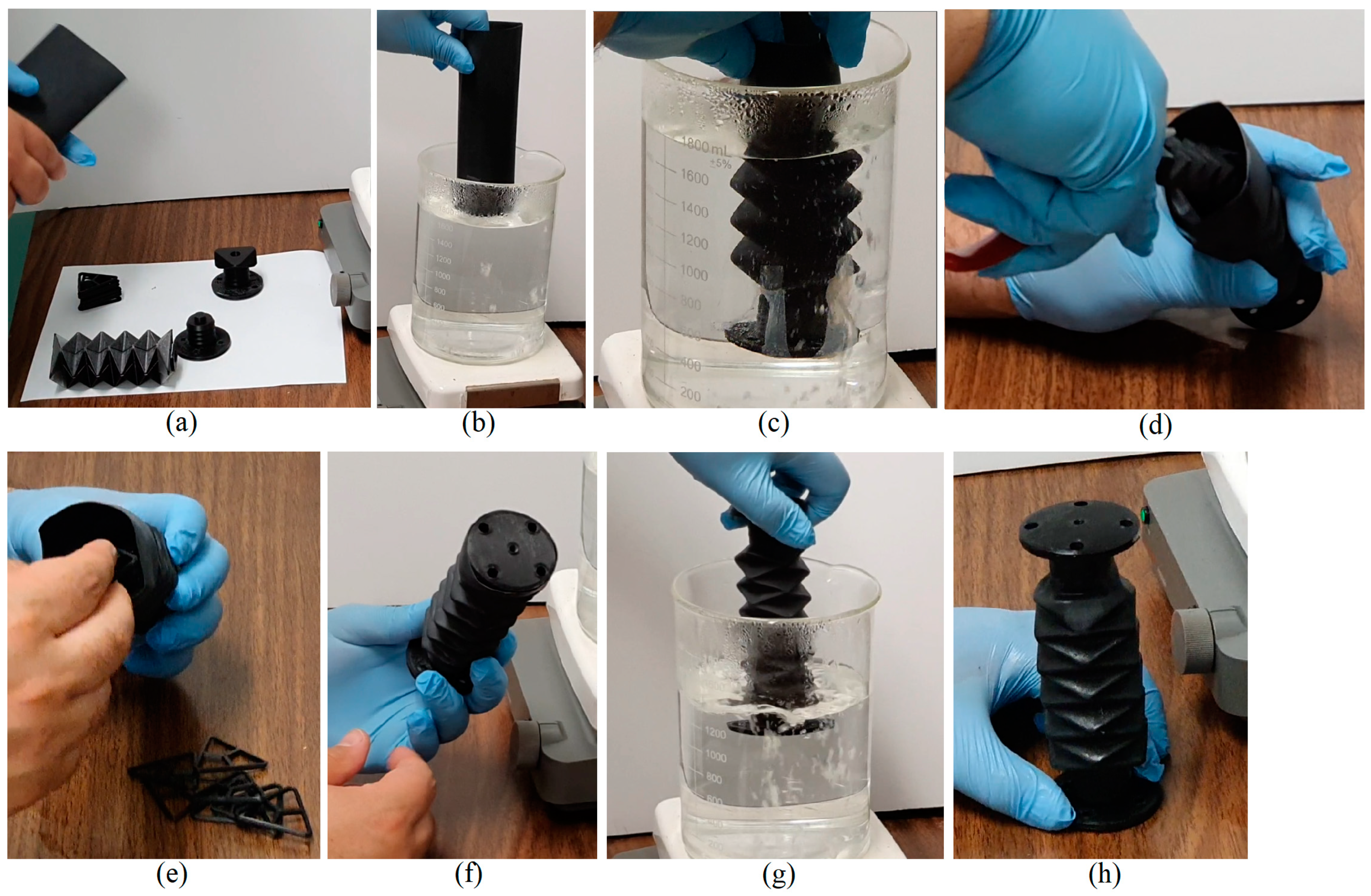
Using a Yoshimura pattern OSPA as an example, the fabrication method is illustrated in
Figure 2. The heat-shrink tubing, multipiece mold, endcaps, and ribs are shown in (a). The heat-shrink tubing in this example is made by Qualtek (type Q2-F4X with 50.8 mm unshrunk diameter). The other parts are made using an inexpensive FDM 3D printer (Prusa, i3 MK3S). The mold pieces and endcaps are made from acrylonitrile butadiene styrene (ABS), since they must not soften during the heat shrinking step. The ribs are made from lower cost PLA, since they are not exposed to heat. The multipiece mold and bottom endcap are assembled first, then placed inside the heat-shrink tube. This assembly is held together using cellophane tape and brought above a container of boiling water as shown in (b). Then, it is slowly immersed in the boiling water up to the depth shown in (c). This immersion step takes about 1 min. The heat of the water makes the tube form around the mold and barbs of the bottom endcaps as shown. The assembly is then taken out of the water and the mold pieces are removed, one at a time starting with the central piece, using pliers. The removal of one mold piece is shown in (d). Next, the support ribs are inserted as shown in (e), followed the insertion of the top endcap to complete the assembly shown in (f). The unformed bottom end of the tube is immersed in the boiling water for about 30 s to form it around the top endcap as shown in (g). After removing the remaining cellophane tape, the finished Yoshimura pattern OSPA is shown in (h). This fabrication method requires less than 10 min to complete. Additional details of the design and fabrication methods can be found in [
24].
3. Generalization to Other Sizes and Materials
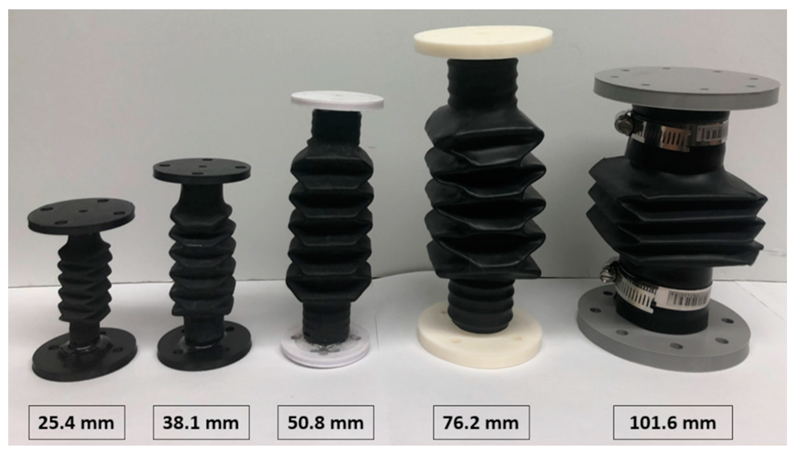
One of the desirable characteristics of OSPA is the actuator can be easily sized for a particular application by scaling up/down the panel dimensions. Similarly, the stroke can be increased/decreased by increasing/decreasing the number of origami units. To illustrate the scalability of the accordion OSPA, we have designed, fabricated, and tested actuators with a range of sizes. The fabricated actuators, as shown in
Figure 3, have
D values of 25.4 mm, 38.1 mm, 50.8 mm, 76.2 mm, and 101.6 mm, respectively. The reason why these numbers were selected is heat-shrink tubing is available in these standard unshrunk diameters. The actuators can also be made from heat-shrink tubing different than the Qualtek Q2-F4X series used in [
24], such as the Sumitube B2 (4X) and B2 (3X) series made by Sumitomo. In fact, the 101.6 mm actuator shown in
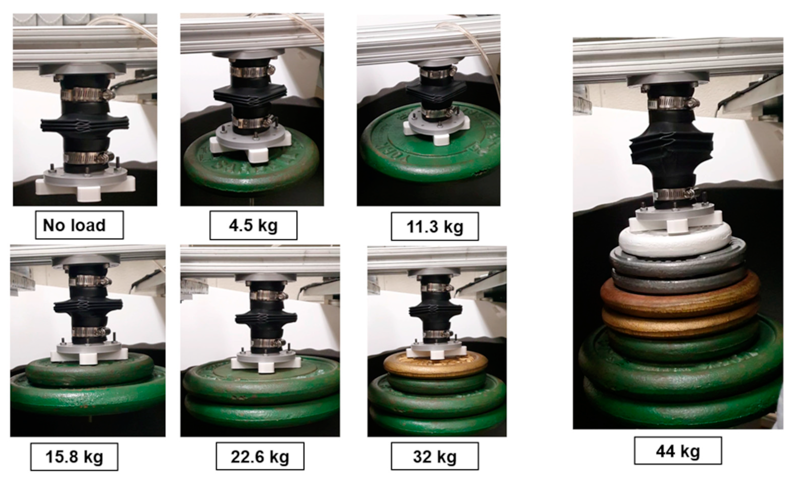
Figure 3 was fabricated from Sumitube B2 (4X) tubing. As the results in
Figure 4 show, this OSPA can lift up to 44 kg at a supply pressure of −85 kPa. It has a mass of 0.32 kg, giving it a force to weight ratio of 124.
4. Long Duration Fatigue Testing
For most applications, an actuator’s fatigue life is an important determinant of its suitability. It follows that having a longer fatigue life makes an actuator suitable for a greater number of applications. An actuator’s materials and design will determine its fatigue life for a specific fatigue test. For example, lifting a larger load will tend to reduce an actuator’s fatigue life. The fatigue tests reported in [
18,
22,
23] were done with no load on the actuator. In our previous work [
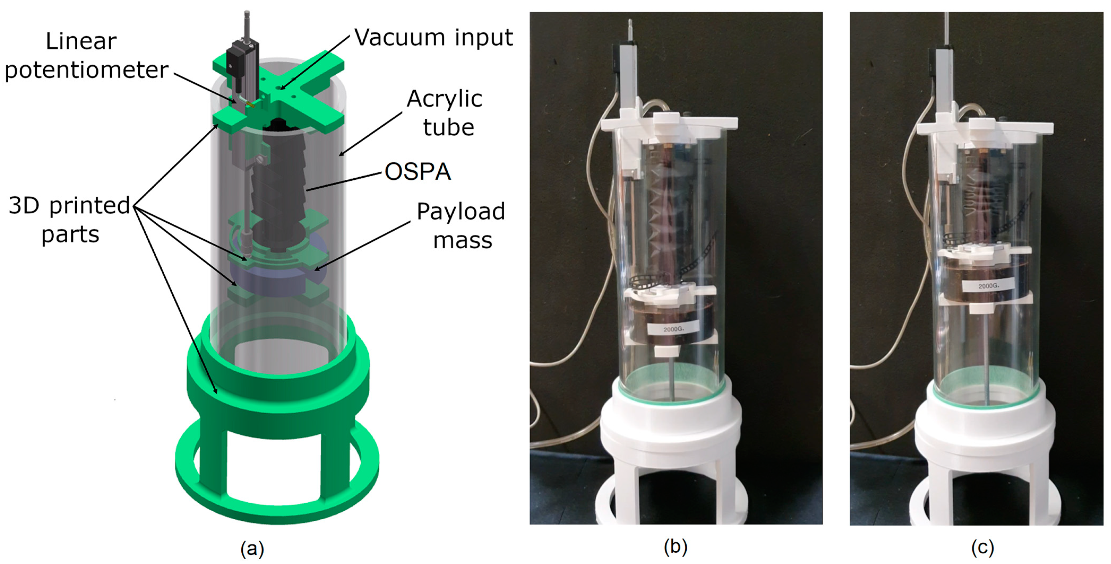
24], the actuator raised and lowered a 0.9 kg mass to complete one fatigue cycle. To apply a greater stress to our OSPA, we increased this mass to 2 kg. We also replaced the vacuum pump with a higher flowrate model (You Cheng Industrial, VN-C4) to allow more cycles to be performed in a given time period. This reduced the period of each cycle from about 33 s to 8 s. The design of the testing apparatus is shown in
Figure 5a. The displacement is measured by a linear potentiometer (Novotechnik, T100), and the pressure is measured by an absolute pressure sensor (SSI Technologies, P51-50-A-B-I36-5V-R). Note that the movement of the actuator is not constrained to only translate in the vertical direction. Bending and twisting motions are allowed during the tests, since there is an 11 mm gap between the 3d printed brackets supporting the payload mass and the acrylic tube, and the potentiometer is connected to the upper 3d printed bracket by a small ball joint. After low-pass filtering at 106 Hz, the signals are sampled at 1 kHz by a PC-based data acquisition system.
The fatigue test was performed on an accordion OSPA made from Qualtek Q2-F4X series heat-shrink tubing with a 50.8 mm unshrunk diameter. The OSPA is shown carrying the 2 kg mass in
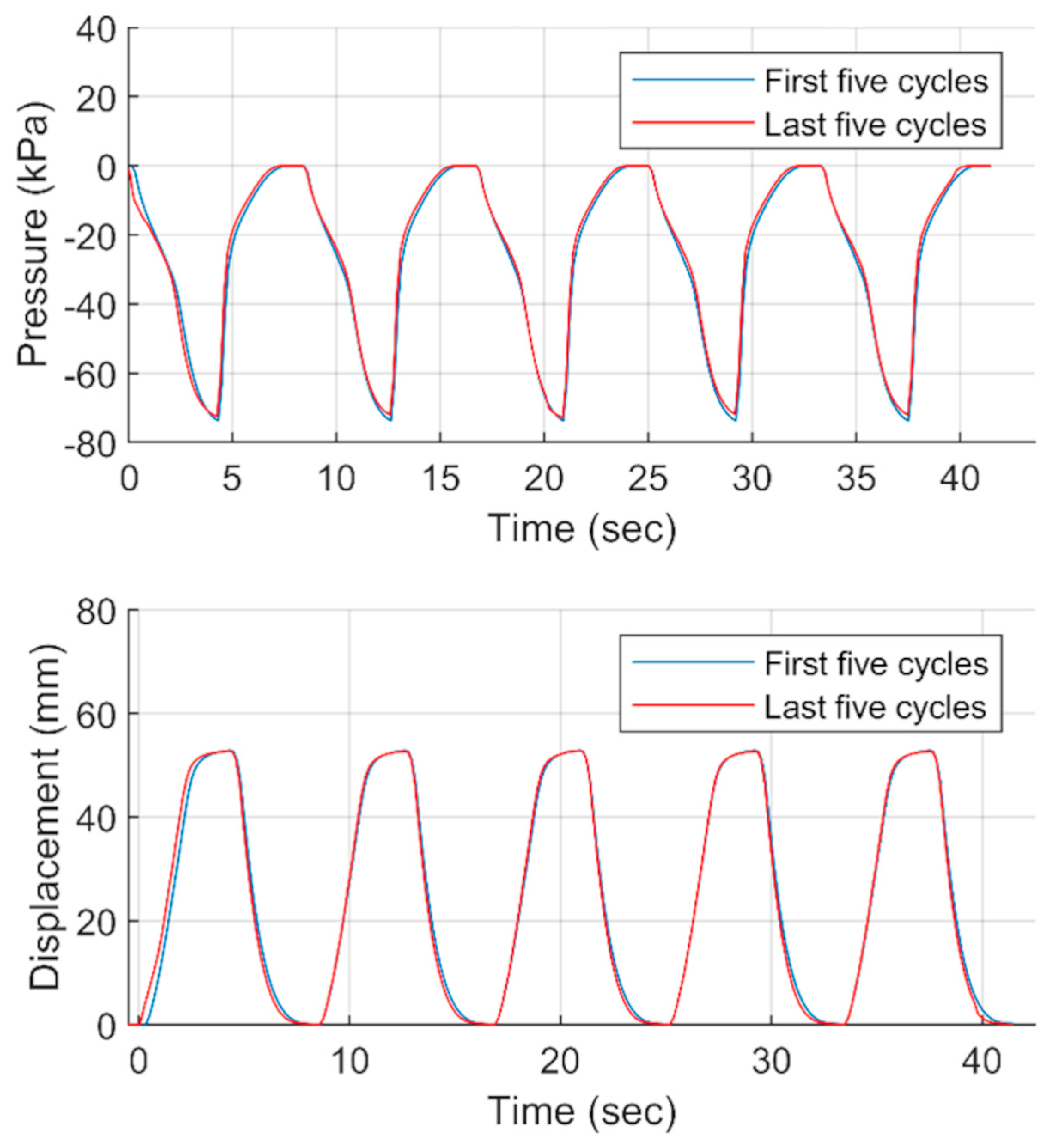
Figure 5b,c. It is shown extended in part (b) and contracted in part (c). The OSPA raises, then lowers this mass to complete one cycle. The test was run for 150,000 cycles and had a duration of over 330 h. The OSPA was visually inspected during and after the test ended, and no defects, such as cracks or holes, were observed. The pressure vs. time, and displacement vs. time plots for the first five cycles and the last five cycles (i.e., cycles 149,996 to 150,000) are overlaid in
Figure 6. These plots demonstrate that the OSPA’s performance was consistent over this lengthy experiment, with the most noticeable differences occurring during the pressure and displacement transients.
5. Comparison with OSPA Developed by Other Researchers
To provide context for this research, a comparison study has been made between the OSPA prototypes and OSPA made by other researchers. Given the practical importance of fatigue life, only OSPA developed by other researchers who reported fatigue test results have been included in this study. The comparison is based on eight performance metrics (occupied volume, mass, work, work to volume ratio (WTVR), work to mass ratio (WTMR), maximum force (MF), maximum displacement (MD), and fatigue life (FL)). The results are listed in
Table 1. Actuators 1–3 are the only OSPA in the literature for which fatigue life data was available. Actuators 4–6 are the OSPA prototypes we have designed and fabricated.
Fairness of the comparison was considered when choosing and calculating these metrics. The work is used in addition to the maximum force since it combines the force output and displacement into one metric. As long as the actuator produces enough work, a mechanism can be used to amplify its force and attenuate its displacement, or vice versa, as required by the application. Regarding the operating pressures, it is well known that using a higher pressure will increase the force and work output of any pneumatic actuator. OSPA numbers 1 and 2 were tested at max. pressures of 10 kPa and 25 kPa, respectively. OSPA numbers 4–6 were tested at a pressure of −80 kPa. Actuator 3 can operate at a pressure larger than 80 kPa. To improve the fairness, its work and maximum force were calculated at a pressure of 100 kPa using the information in [
23]. Regarding the occupied volume, an actuator typically has components at both ends for mounting/attaching it. Those end pieces increase the actuator’s occupied volume. Since actuators 1 and 2 did not use end pieces, the occupied volume was calculated for all actuators without the end pieces included.
In terms of the performance metrics, actuator 1 is the lightest, has the best MD and the second best WTMR, but it suffers from a very short FL. Actuator 2 has the worst overall performance. It ranks last in terms of WTVR, WTMR, FL and second last in terms of MD. Although actuator 3 produced the most work, it is significantly larger and heavier than all of other actuators, thus, its WTVR and WTMR are not great. With the new OSPAs (actuators 4–6), the smaller diameter of actuator 4 obviously reduced its occupied volume and mass, but its WTVR and WTMR are the worst of the three. The performance of the Yoshimura pattern OSPA (actuator 5) was intermediate. The larger accordion pattern OSPA (actuator 6) ranked first in terms of WTVR, WTMR, MF and FL, and has the second best MD. It can be concluded from this comparison that actuator 6 is the best overall performer.
6. Design Optimization
6.1. Optimization Problem Definition and Constraints
The goal of the optimization is to find the geometry of an accordion pattern OSPA that maximizes its output work. We have chosen to maximize the output work because: (1) The work combines the force and displacement into a single objective which avoids the computational burden of multi-objective optimization, and (2) A mechanism can be used to amplify the force and attenuate the displacement, or vice versa, as needed by the application.
The optimization is based on a parametric FEA model of the OSPA (including its internal support ribs and endcaps). It was decided to keep the dimension D constant so all candidate actuators included in the optimization can be made from the same diameter heat-shrink tubing. A value of D = 50.8 mm, and the Qualtek Q2-F4X heat-shrink tubing, were chosen to facilitate the experimental validation. The OSPA’s number of origami units was fixed at 2.5. This was done to reduce the FEA simulation time compared to the time needed for simulating OSPA with more units. Additionally, if the optimization method works effectively with a 2.5 unit OSPA, then it should also work well when more origami units are included.
The design parameters to be optimized are the diameter ratio,
, initial folding angle,
, and actuator wall thickness,
t. Since
D has been fixed at 50.8 mm, the software can calculate
using
, and the panel dimensions
a-
d using Equations (1)–(4). This information is used to establish the actuator’s geometry (including the length and width of the support ribs) in the FEA simulation as explained in
Section 6.2.
The thickness,
t, is being optimized since a smaller thickness will reduce the bending stiffness of the walls and help the OSPA fold at its creases more easily. This will result in a larger output work since the pneumatic force required to fold and compress the actuator will be smaller. However, when the thickness is decreased too much, the bending of the panels will increase, distorting the OSPA’s shape, and reducing its output work. Therefore, an optimal thickness will exist. The
t value of the fabricated actuator depends on the heat-shrink tubing’s unshrunk thickness, the tubing’s shrunk thickness (also called the “recovered thickness”), and the amount the tubing must shrink to form the actuator’s shape. Although, the unshrunk thickness of a particular brand and type of heat-shrink tubing cannot be changed, the optimal
t value can be used to help select the best tubing from the available choices. These issues will be further discussed when the optimal
t value for the 2.5 unit OPSA is presented in
Section 6.5.
Constraints on the design parameters are necessary to avoid failed FEA simulations (and the corresponding failures of OSPA prototypes), and to improve the optimization efficiency by limiting the search space. These constraints are listed in
Table 2. Regarding the
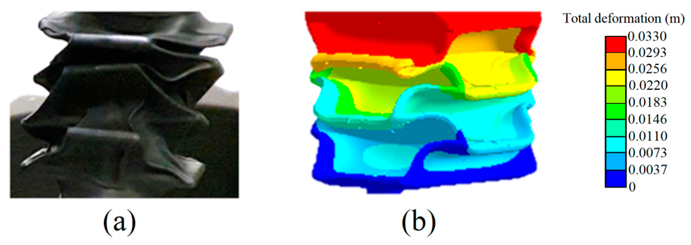
, when it increases, the size of the actuator’s panels will also increase. This tends to increase the actuator’s output work. However, under the effect of higher vacuum pressures and larger loads, the larger panels tend to bend or warp instead of folding at the creases. This causes convergence problems with the FEA, and failed folding with prototypes. This was observed to start happening when
exceeds 2.4. An example of this type of failure happening with a real OSPA and its FEA simulation is given in
Figure 7. To avoid this, the upper bound on
was set to 2.4. When
and the load are both large, the internal support ribs tend to slip from their original locations at the accordion pattern’s internal valleys. If this happens, the actuator will fail to fold, and the FEA simulations will not converge. This problem was avoided by setting the upper bound on
to 110°. Finally, an upper bound of 0.5 on the von Mises strain calculated by the FEA was included based the FEA software developer’s recommendation that the hyperelastic material model should only be used in the range of the stress–strain test data [
25]. More information about our hyperelastic material model of the Q2-F4X heat-shrink tubing is provided in [
24].
6.2. Optimization Workflow
The optimization employs the Autodesk Inventor, Ansys Workbench and Ansys DesignXplorer software packages. The workflow follows these steps:
A parametric CAD model is developed in Autodesk Inventor that includes all parts of the OSPA (i.e., flexible body, support ribs, and endcaps).
The design parameters are imported into the Ansys Workbench FEA simulation software. This allows the CAD model to be automatically controlled by the FEA software.
The lower and upper limits of each parameter are chosen as explained in
Section 6.1.
A sufficient number of design points, , are generated using the design of experiment (DOE) technique.
Each design point is evaluated by running FEA simulations to determine the corresponding output work.
The response surface (RS) method is used to mathematically fit a model to the DOE points’ calculated work values.
The chosen optimization algorithm looks for the optimal point on the generated RS.
The optimal point generated by the optimization algorithm is verified by solving the FEA using the optimal design parameters.
In the next subsections, the main steps of the workflow will be explained in more detail.
6.3. Two-Part FEA Simulation Procedure
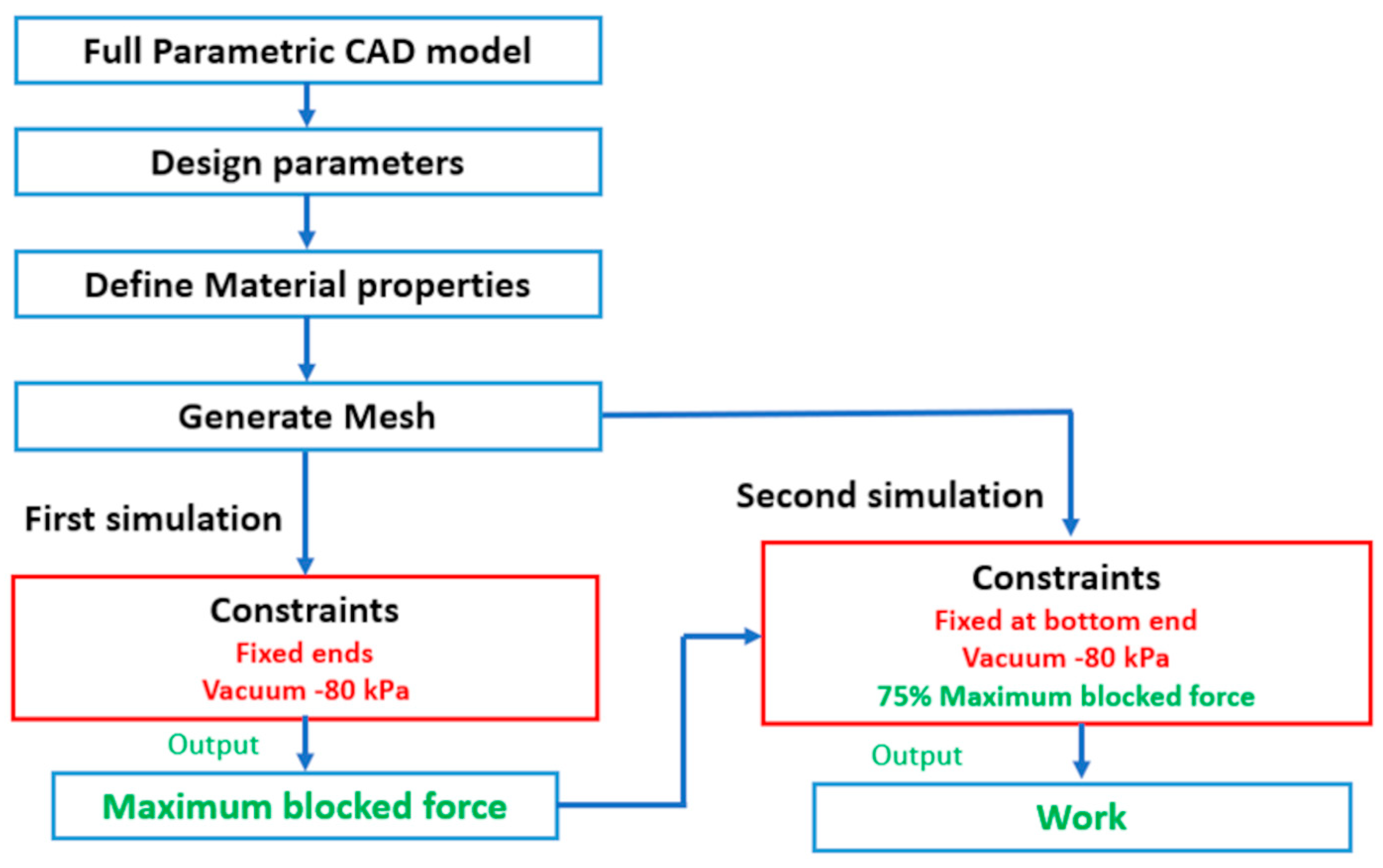
To find the OSPA’s work output (i.e., step 5 in the optimization workflow), we have developed a procedure utilizing two FEA simulations. In the first FEA simulation, the maximum blocked force (i.e., the blocked force at zero contraction) is predicted for a vacuum pressure of -80 kPa at each of the design points generated by the DOE technique. The second FEA simulation predicts the maximum displacement at each of those design points for a vacuum pressure of -80 kPa, and 75% of the maximum blocked force from the first simulation applied as a load. The approximate work done by the actuator is calculated by multiplying the 75% maximum blocked force by the maximum displacement of the actuator subject to that applied load. The 75% force scaling factor (FSF) was chosen based on our knowledge of the force vs. displacement behavior of previous OSPA prototypes. The conventional method for determining the output work is to first calculate the points on the force vs. displacement curve by performing many FEA simulations, then calculating the area under the curve by integration. Our approximate method requires performing only two FEA simulations, so it is much more computationally efficient than the conventional method. Our two-part FEA workflow for calculating the OSPA’s approximate work output is illustrated in
Figure 8.
6.4. Details of the Optimization Steps
The details of workflow steps 4–7 are given in this section. We chose the RS method for its computational efficiency. Unlike direct optimization methods, it does not need to run the FEA simulation many times to solve the optimization problem. For the DOE, we selected the Latin hypercube sampling (LHS) DOE method, since it is an advanced form of Monte Carlo sampling that avoids clustering samples. In an LHS design, no point shares a row or column of the design space with any other point [
26]. The main advantage of this method that it saves computation time by avoiding the creation of duplicate points. The LHS generated a set of 15 design points. The Kriging method was selected for obtaining the RS, since it is known to provide an improved RS quality and fits higher-order variations of the output parameter [
26,
27]. To find the optimal point on the RS, we chose a genetic algorithm (GA), since GA have improved efficiency for global optimum search compared to gradient-based algorithms. These were steps implemented using Ansys DesignXplorer.
6.5. Optimization Results and Experimental Validation
On a Windows 10 laptop with a 2.6 GHz, 6 core, Intel i7 CPU and 16 GB RAM, the total computation time for the optimization process was about 300 min. The optimal design point equaled (2.39, 96°, 0.842 mm). The optimal value of the work output equaled 3.36 J. To check the RS, the two-part FEA simulation procedure was run for the optimal design point. The difference between the work at the RS point and the work at the optimal point was only 1.1%, which demonstrates the accuracy of the RS.
Two 2.5 unit accordion pattern OSPAs were fabricated to validate the optimal design point. The first OSPA was fabricated with the following arbitrary, non-optimized, parameters: and . The second OSPA was fabricated using the optimal values of the parameters, i.e., and . Unfortunately, setting t to a specific value, such as 0.842 mm, is not possible with our fabrication method since the selection of commercial heat-shrink tubing is limited. However, the optimal t value can be used to help choose the best tubing from those available. The measured t value for both prototypes is ~1 mm so it is thicker than the 0.842 mm optimal value so the Qualtek Q2-F4X tubing may not be the best choice. (Note: The measured t value was obtained by averaging the thicknesses measured at many locations). The unshrunk thickness of the Q2-F4X tubing is ~0.5 mm, and the fully shrunk thickness is ~1.7 mm. The Sumitube B2 (4XC) tubing is thinner. It has an unshrunk thickness of ~0.3 mm and a fully shrunk thickness of ~1.2 mm so it should be able to produce an actuator with a thickness closer to 0.842 mm. However, the B2 (4X) is not made from the same polyolefin as the Q2-F4X so establishing that it produces a more optimal actuator would require acquiring stress–strain data of B2 (4X) test specimens, fitting a hyperelastic material model, and repeating the optimization process for this tubing. That is beyond the scope of this paper but will be explored in our future work.
The fatigue testing apparatus setup presented in
Section 4 was utilized to test both actuators lifting a 10 kg payload. Each test was repeated five times using a vacuum pressure of −80 kPa. The output work values for the two OSPA were calculated by multiplying the average value of the actuator’s stroke by the 98.1 N payload weight. Moreover, FEA simulations predicting the strokes of both the optimized and non-optimized accordion OSPAs were created and run for the same 10 kg payload.
The results are presented in
Table 3. The simulation results indicate that the work output of the optimized actuator has been improved by 55%, while the experimental tests show an improvement of 53%. While the improvement percentages are very similar, the values of the predicted stroke and work are about 16% larger than the experimental values. The reasons for the differences include the approximate value used for the actuator’s wall thickness, the assumption of uniform wall thickness, and errors in the simulated actuator’s stiffness caused by errors in the material models and the friction forces between the internal support ribs and the actuator’s walls. In reality, the wall thickness is nonuniform. When the tubing acquires the shape of the mold it is not fully shrunk. The amount the tubing shrinks and the resulting increase in its thickness depends on the perimeter of the cross-section of the actuator after it has been formed. The perimeter of the cross-section varies over the length of each origami unit, so it varies periodically over the actuator’s effective length,
. This means the wall thickness also varies over
. Although the thickness is nonuniform, the thickness variations are consistent for actuators produced using the same mold and heat-shrink tubing. This thickness consistency along with the consistency of the actuators’ fabricated shape are the reasons why the blocked force test results for two actuators fabricated using the same mold are very similar (as shown in section VIII.C of [
24]).
7. Conclusions
In this paper, we have expanded and generalized our research on the design, fabrication, and testing of OSPA. A computationally efficient method for maximizing an OSPA’s output work by design optimization is proposed. Its procedure for calculating the approximate work output of a candidate actuator using only two FEA simulations is much more efficient than the conventional method for determining the output work by integrating the force vs. displacement curve after performing many FEA simulations. The experimental results with the non-optimized and optimized prototypes demonstrated similar percentage improvements in the work output. The results in
Section 3 showing that our fabrication method may be used to produce OSPA with a range of sizes and out of heat-shrink tubing other than Q2-F4X demonstrate its generalizability. Notably, an OSPA made from Sumitube B2 (4X) is shown to be capable of lifting a 44 kg mass. The results from a 150,000-cycle fatigue test with a 2 kg payload demonstrate the superior durability of the OSPA made from Q2-F4X tubing by our fabrication method. Previously published OSPA fatigue tests were done using no load or less than 50% of the load used in our tests. Our test duration is also 15 times longer than the longest previously reported test.
Several research directions will be pursued to improve the actuators’ future design and performance. First, the design optimization has only been done for an OSPA made from Q2- F4X. The measured average wall thickness with Q2-F4X was not close to the optimal value, so the thinner Sumitube B2 (4X) tubing will be investigated to see if it produces prototypes with a thickness closer to the optimum. As mentioned in
Section 6.5, this will involve getting B2 (4X) stress–strain data, fitting a hyperelastic material model, and then repeating the optimization, fabrication, and testing. Second, the sensitivity of the optimal solution to the FSF (that is currently 75%) will be investigated to see if other values yield an actuator with a larger output work. Third, the thickness and edge radius of the support ribs will be added to the set of design parameters being optimized. The current thickness and edge radius of the ribs are 3 mm and 1.5 mm, respectively. Thinner ribs will increase the stroke of an actuator but will mechanically fail if they are too thin. Materials and methods for fabricating thin and strong ribs will be investigated. Fourth, methods for modeling and simulating the actuator’s nonuniform wall thickness will be investigated. This is expected to improve the predictive accuracy of the FEA simulation that currently assumes the thickness is uniform. Fifth, OSPA designs with more than 2.5 units will be optimized and tested to evaluate the performance gains achievable with longer actuators. Sixth, since the current weight of the endcaps constitutes a large portion of an OPSA’s total weight, the design of lightweight endcaps will be pursued.


