1. Introduction
The impact of climate change has resulted in an increased demand for more energy-efficient technologies, and transportation electrification has emerged as a potential solution with which to partially address this challenge [
1,
2,
3]. With their ability to convert electrical into mechanical energy and vice versa, electrical machines represent a key technology for reducing greenhouse gas emissions [
4,
5,
6,
7], and they find widespread applications ranging from transportation to power generation [
8,
9,
10]. Apart from being compact, electrical machines employed in airplanes, ship propulsions, and electric vehicles must feature a great reliability level, since any failure might cause significant consequences due to the safety-critical nature of the applications [
11,
12,
13].
For electrical machines, enhanced reliability is often reached through fault-tolerant designs [
14,
15] and reliability-oriented methodologies [
16]; however, ambient factors (temperature, humidity, etc.), as well as wearing out from prolonged use, might induce failures [
17,
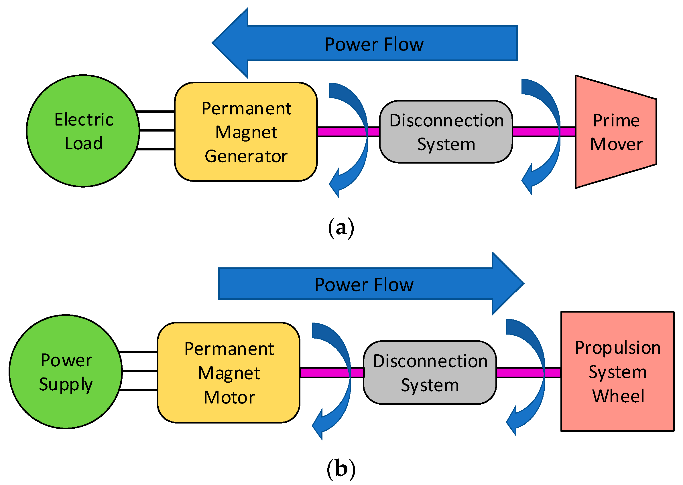
18] that could quickly escalate, compromising the whole system integrity. In these circumstances, failure escalation/propagation could be prevented by adopting a disconnection system that mechanically decouples the electrical machine from the rest of the system. As depicted in
Figure 1a, the disconnect actuator disengages the electrical machine shaft from the primary mover if the former is acting as a generator. Conversely, the electrical machine shaft is decoupled from the propulsion system wheel in cases of motor mode operations, as shown in
Figure 1b.
Mechanical clutches are among the most commonly used disconnection systems [
19,
20], although they reveal a number of drawbacks, such as mechanical wear and tear, which impose considerable maintenance [
21,
22,
23]. An alternative disconnection system is presented in [
24], where a coaxial magnetic coupling [
25] is employed to guarantee the contactless torque transfer in engaged mode, while the disconnection function is performed by an electromagnetic device (i.e., solenoid actuator). The latter consists of a static part featuring a coil wound around a ferromagnetic core and a moving part, namely the plunger, which is mechanically connected to the magnetic coupling inner rotor. In the event of failure detection (either electrical or mechanical fault occurring on the electrical machine), the electromagnetic device’s coil is supplied by a direct current generating a magnetic field; the plunger is withdrawn by the action of the associated electromagnetic force and the magnetic coupling inner rotor is extracted from the outer one interrupting the torque transmission. The disconnection actuator architecture is illustrated in
Figure 2, and its main benefits are as follows: (1) efficient torque transmission, (2) reduced maintenance compared to conventional disconnection systems (i.e., mechanical clutches), and (3) a fast response in interrupting the transmitted torque in the event of failure detection.
In terms of applications, the disconnection actuator is characterized by a fair versatility, and it could be installed in propulsion systems (i.e., an electrical machine in motor mode) for e-mobility or in generation systems (i.e., an electrical machine in generator mode); therefore, the design specifications (i.e., rated torque and speed), which depend on the application nature, might vary in a wide range.
In this paper, the design procedure of two disconnection actuators, one meant for high-speed applications (i.e., Actuator 1) and the other intended for high-torque applications (i.e., Actuator 2), is presented, and particular attention is given to electromagnetic device optimization. Starting with benchmark specifications, the coaxial magnetic coupling is sized and the resulting axial force is determined via finite element simulations. The axial forces are used as input data for designing the electromagnetic device, since the developed force must exceed the magnetic coupling axial force to ensure the disengagement. In order to maximize the force developed by the electromagnetic device, two trade-off studies are carried out in order to select the optimal slot opening length and position. Once their designs are finalized, the two disconnection actuators (i.e., Actuator 1 and Actuator 2) are manufactured and an experimental test campaign is conducted. In order to assess the disconnection capability, tests are performed in the most demanding conditions in terms of the required disconnection force, which corresponds to zero torque transmitted. The collected results on both disconnection actuators prove the effectiveness of an optimized design and short disconnection time.
2. Coaxial Magnetic Coupling Design
To avoid failure propagation and boost system safety, the disconnection actuator could be integrated into several engineering systems, ranging from e-mobility applications (e.g., aircraft, electric vehicle, and ship) to power generation systems (e.g., gensets) that combine internal combustion engines and electrical generators to produce electrical power [
26]. Both potential applications are evaluated by properly selecting the design specifications according to the rated speed and torque values listed in
Table 1.
In particular, the benchmark specifications associated with Actuator 1 (i.e., 20,000 rpm and 50 Nm) mirror those of a generic e-mobility propulsion system, which is typically characterized by higher rated speed (i.e., high-speed applications). On the other hand, Actuator 2 (i.e., 5000 rpm and 100 Nm) features benchmark specifications commonly related to power generation applications, where the rated torque is higher (i.e., high-torque applications). Based on the specifications reported in
Table 1, the initial step of the disconnection actuator design process involves coaxial magnetic coupling sizing, because the disconnection force demanded by the electromagnetic device (i.e., input data for the electromagnetic device design) depends on the magnetic coupling characteristics.
From a structure perspective, the coaxial magnetic coupling consists of two concentric rotors (i.e., outer and inner rotors) made of ferromagnetic material [
27]. On the inner surface of the outer rotor, a first set of permanent magnets is glued with alternative polarity, while a second set of permanent magnets is placed on the outer surface of the inner rotor [
28,
29]. Relying on the interaction between alternating permanent magnets facing each other, the torque applied to one rotor shaft is transmitted to the other rotor [
30]. The transmitted torque is a function of the shift angle between the permanent magnet sets [
31], and two operating limit conditions can be identified:
Zero transmitted torque, which occurs when the two sets of permanent magnets are radially aligned (i.e., a shift angle equal to zero).
Maximum transmitted static torque, which takes place when the two sets of permanent magnets are radially shifted by the maximum allowable angle.
Imposing the rated torque values given in
Table 1 equal to the maximum transmitted static torque, the two coaxial magnetic couplings are sized through a 2D finite element analysis via Simcenter MAGNET software (Version 2021.1). Although analytical methods allow satisfactory design results to be achieved [
32,
33], in this work a finite element method is employed to better evaluate the magnetic saturation impact on the transmitted torque performance. The resulting parameters are summarized in
Table 2, and apart from the different radii at the airgap (whose value affects the plunger radius), the two magnetic couplings feature different pole pair numbers. In fact, a pole pair number equal to 13 is selected to ensure the target transmitted torque of 50 Nm required by Actuator 1, while the magnetic coupling employed in Actuator 2 is characterized by 16 pole pairs to transfer 100 Nm.
Finite element simulations are also used to verify the magnetic saturation levels of both magnetic couplings, and the corresponding flux density maps are reported in
Figure 3 for the two operating limit conditions. When analyzing the obtained flux density distributions, no major issue in terms of magnetic saturation is unveiled.
The transmitted torque capability of the designed magnetic couplings is experimentally validated against the finite element simulation results. In
Figure 4, the transmitted static torque as a function of the mechanical shift angle is shown and a fair agreement between the simulation and experimental results is found, whose mismatch is mainly ascribed to the 2D nature of the finite element analysis.
3. Axial Pulling Force
In magnetic couplings, an axial force (i.e., pulling force) is exerted between the permanent magnet sets, which tends to keep in place inner and outer rotors; thus, the force developed by the electromagnetic device must overcome the permanent magnets pulling force for successfully accomplishing the disconnection. This axial pulling force is simultaneously angle-dependent and position-dependent [
31]. Due to the shift angle dependency, the pulling force magnitude decreases as the angular displacement increases. In other words, a lower pulling force is established when a higher torque is transmitted. Therefore, disconnection will result, which is more demanding at null transmitted torque (i.e., zero shift angle). On the other hand, the pulling force amplitude varies as the inner rotor moves axially with respect to the outer rotor during the disconnection stage. In this condition, the transmitted torque decays as the axial displacement between the permanent magnet sets increased (i.e., lower facing surface between permanent magnets).
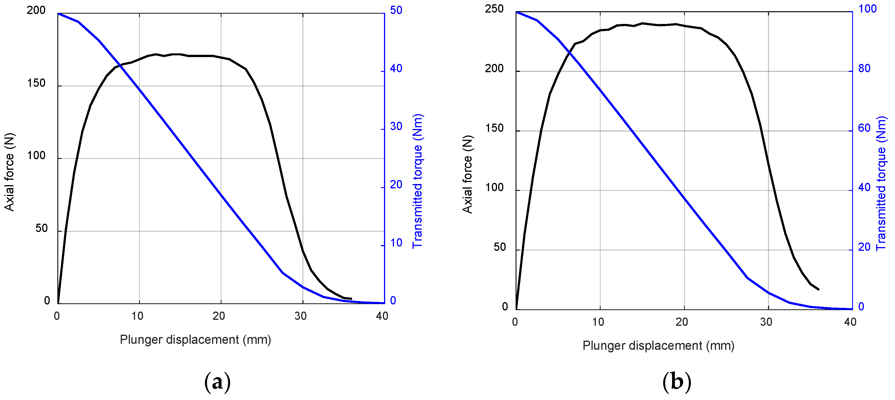
Relying on the designs presented in
Section 2, the corresponding axial pulling force, as a function of the plunger displacement (i.e., axial displacement between permanent magnet sets), is determined via finite element simulations. These simulations are carried out considering the worst-case scenario in terms of the pulling force, which occurs at zero shift angle (i.e., zero transmitted torque). For both Actuator 1 and Actuator 2, the collected results are illustrated in
Figure 5, and the black line trend represents the minimum target force for correctly designing the electromagnetic device. In particular, Actuator 1 demands a minimum axial force of 170 N, whereas 240 Nm is necessary for Actuator 2.
As mentioned earlier, higher axial plunger displacements result in lower transmitted torque. Hence, a new finite element simulations campaign is performed, considering the maximum transmitted torque condition (i.e., maximum shift angle) and varying the axial displacement between permanent magnet sets. The simulation outcomes are provided in
Figure 5 using the blue line and they allow for the determining of the minimum plunger displacement (i.e., plunger stroke) that ensures zero transmitted torque, which corresponds to the disconnection accomplishment condition. Referring to the blue line trend in
Figure 5, the plunger stroke must be at least 27.5 mm and 30 mm for Actuator 1 and Actuator 2, respectively. In
Table 3, the specifications for designing the electromagnetic device are summarized.
4. Electromagnetic Device Design and Optimization
Assuming the specifications listed in
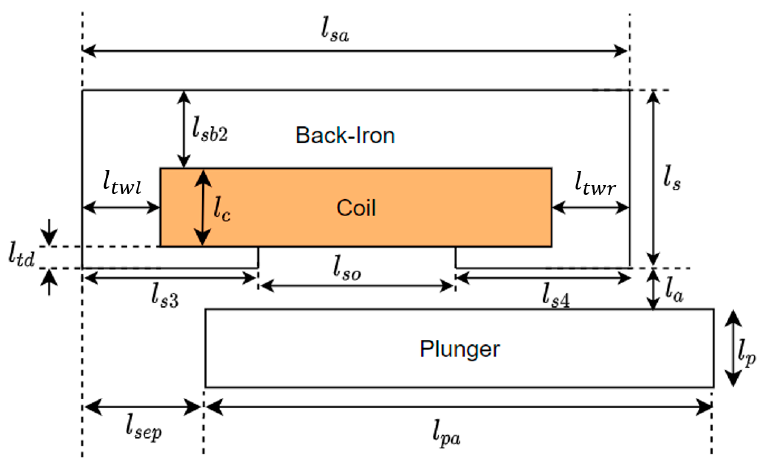
Table 3 to be target values, the design optimization of the electromagnetic device for both disconnection actuators (i.e., Actuator 1 and Actuator 2) is performed by means of trade-off studies. The fully parametrized 2D model shown in
Figure 6 is implemented within finite element software, and its main parameters are outlined in
Table 4.
A preliminary trade-off analysis is run to scale down the number of parameters and identify those that most affect the force developed by the electromagnetic device. These critical parameters are, in turn, the DC flowing through the coil, the airgap thickness (
), the slot opening length (
), and the slot opening location (
and
). Although the DC plays an important role in the disconnection force intensity, its value is constrained by the DC power supply feeding the coil. For this reason, the DC current is assumed to be equal to 15 A, which is the maximum current provided by the available DC source. Additionally, a 2 mm airgap thickness is supposed in order to ensure safe mechanical operations. Every remaining critical parameter (i.e., slot opening length and slot opening position) undergoes a further trade-off study for optimization proposes (
Section 4.1 and
Section 4.2), while the other parameters are held constant to the values listed in
Table 5.
4.1. Slot Opening Length () Trade-Off Study
The trade-off analysis of the slot opening length (
) is conducted by gradually increasing its value in steps of 5 mm until the maximum value is reached (i.e., open slot configuration). The slot opening maximum value is obtained when the slot opening length is equal to the slot width (i.e.,
). While the slot opening length (
) varies, its location is consistently kept at the middle of the ferromagnetic core (
). The results of the first trade-off study are summarized in
Figure 7a,b for Actuator 1 and Actuator 2, respectively. In each subfigure, the disconnection force is plotted as a function of the plunger displacement (i.e., axial position) for several slot opening length values.
Focusing on
Figure 7a’s results (Actuator 1), the electromagnetic device develops a disconnection force greater than the required force (i.e., blue dashed line) for slot opening length values lower than 25 mm. Considering the findings reported in
Figure 7b (Actuator 2), the slot opening necessary to overcome the permanent magnets’ pulling force should be smaller than 35 mm. For both of the disconnection actuators, the starting force (i.e., force produced at zero plunger displacement) is higher when the slot opening length is smaller, while the location of the peak force occurs at a lower plunger displacement as the slot opening length decreases. In fact, a reduction in the slot opening length (
) leads to longer tooth shoe widths (
and
), and a lengthy right tooth shoe width (
) offers a lower reluctance path to magnetic flux going from the plunger to the ferromagnetic core. Such behavior suggests that, by shifting the slot opening to the left (i.e.,
), a higher disconnection force will be developed due to the lower reluctance of the flux path.
4.2. Slot Opening Location ( and ) Trade-Off Study
The aim of the second trade-off study consists of analyzing the impact of the slot opening position on the disconnection force developed by the electromagnetic device. In this trade-off analysis, the slot opening length (
) is kept constant throughout the investigation and its values are equal to the optimum determined in the previous study, namely 25 mm for Actuator 1 and 35 mm for Actuator 2. Starting from the initial position (i.e., 0 mm), corresponding to the condition
, and
as the maximum, the slot opening position is gradually moved from the left to the right edge of the ferromagnetic core in steps of 2 mm. Therefore, the last examined slot opening position (i.e., 10 mm) reflects the circumstance of
, and
as the maximum. For each slot opening position, a 2D finite element simulation is run and the developed disconnection force as a function of the plunger displacement is obtained. The collected results are summarized in
Figure 8a,b for Actuator 1 and Actuator 2, respectively.
In analyzing the results shown in
Figure 8a (Actuator 1), any slot opening position lower than 4 mm (i.e.,
smaller than 14 mm, assuming that
equal to 10 mm) allows for the development of sufficient force to properly perform the disconnection function. Similarly, a slot opening position smaller than 6 mm (i.e.,
smaller than 16 mm, with
equal to 10 mm) ensures sufficient force for disconnection in Actuator 2 (
Figure 8b). In both of the disconnection actuators, the starting force increases as the slot opening position moves from the right to the left of the core (i.e.,
grows at the expenses of
). In other words, higher starting force values are achievable by locating the slot opening in the direction opposite to that travelled by the plunger during disconnection. In analyzing the peak force location, its value decreases as the slot opening position moves from the right to the left of the core (i.e., from 10 mm to 0 mm).
4.3. Electromagnetic Device Final Design and Manufacturing Considerations
Following the outcomes of both trade-off studies and considering the manufacturing constraint related to the slot fill factor, the final design parameters have been determined for both disconnection actuators, as listed in
Table 6.
The slot fill factor represents the ratio between the copper area and the slot surface. From a manufacturing perspective, the whole slot surface is not fully filled by copper wire due to (1) the round shape of the wire cross-section and (2) the insulating layer covering the copper wire (i.e., enameled magnet wire). Therefore, the coil installation is guaranteed by selecting a fill factor lower than 1 (e.g., empirical value of 0.5).
Since the DC is kept constant at 15 A and the fill factor is set as 0.5, the number of turns is determined and the wire diameter is adjusted based on the commercially available cross-sections. Some slight alterations of the slot area might be required to easily accommodate the enameled magnet wire inside the slot. Such changes come at the expense of the teeth width ( and ) and the core back iron thickness (), and, as a consequence, the saturation level of electromagnetic devices needs to be verified via 2D finite element simulations. This check is performed at two working limit conditions:
Disconnection actuator in engaged mode (i.e., pre-fault detection situation), where the electromagnetic device is in the initial position and the torque is transferred through the magnetic coupling;
Disconnection actuator in disengaged mode (i.e., post-fault detection situation), where the electromagnetic device is in the final position and the torque transmission is inhibited.
Considering the dimensions and materials reported in
Table 6, the flux density maps in engaged mode (left-hand side) and disengaged mode (right-hand side) are given in
Figure 9a,b for Actuator 1 and Actuator 2, respectively. Although higher flux density values are reached in disengaged mode, the finite element results confirm that the magnetic circuit is far from being heavily saturated.
5. Experimental Validation of the Disconnection Capability
According to the dimensions given in
Table 2 (i.e., coaxial magnetic coupling parameters) and
Table 6 (i.e., electromagnetic device parameters), the two disconnection actuators are prototyped and manufactured. Wire electrical discharge machining (EDM) is used during the building process of the stainless steel parts (i.e., inner and outer rotors, plunger, and core), although additive manufactory technology [
34,
35,
36], also known as 3D printing, could have also been adopted. The plunger (i.e., the axially moving part of the electromagnetic device) is mechanically coupled to the inner rotor of the coaxial magnetic coupling via a ball spline shaft, which allows simultaneous rotation and translation motion. A view of the main components before assembling is given in
Figure 10a,b for Actuator 1 and Actuator 2, respectively.
As mentioned in
Section 3, the permanent magnets’ pulling force is angle-dependent, and it is greater when the shift angle is null (i.e., zero transmitted torque). For this reason, the disconnection capability of Actuator 1 and Actuator 2 is verified in static conditions (i.e., worst-case scenario), which corresponds to the circumstance of zero transmitted torque. The experimental test bench is shown in
Figure 11, and it consists of a laboratory DC power supply, an oscilloscope, a hall effect current probe, and a differential voltage probe. Furthermore, both disconnection actuators are equipped with a set of integrated sensors, such as a linear position sensor for measuring the plunger axial displacement, one resolver per shaft for determining the shift angle, and a force sensor. The measurements collected by the integrated sensors are acquired via the use of a data logger.
During the experimental test, the coil of the electromagnetic device is suddenly fed through the DC power supply while the shift angle is null (i.e., the two sets of permanent magnets are radially aligned) and the disconnector actuator is in engaged mode (inner and outer rotors of the coaxial magnetic coupling are axially aligned). The voltage applied to the coil and the resulting current are measured and acquired by the oscilloscope. As the current flowing through the coil builds up, the plunger begins the axial movement, extracting the inner rotor out from the outer rotor. The disconnection transient is relatively fast, and it is considered extinguished when the plunger engages the mechanical latch mounted at the end of its stroke.
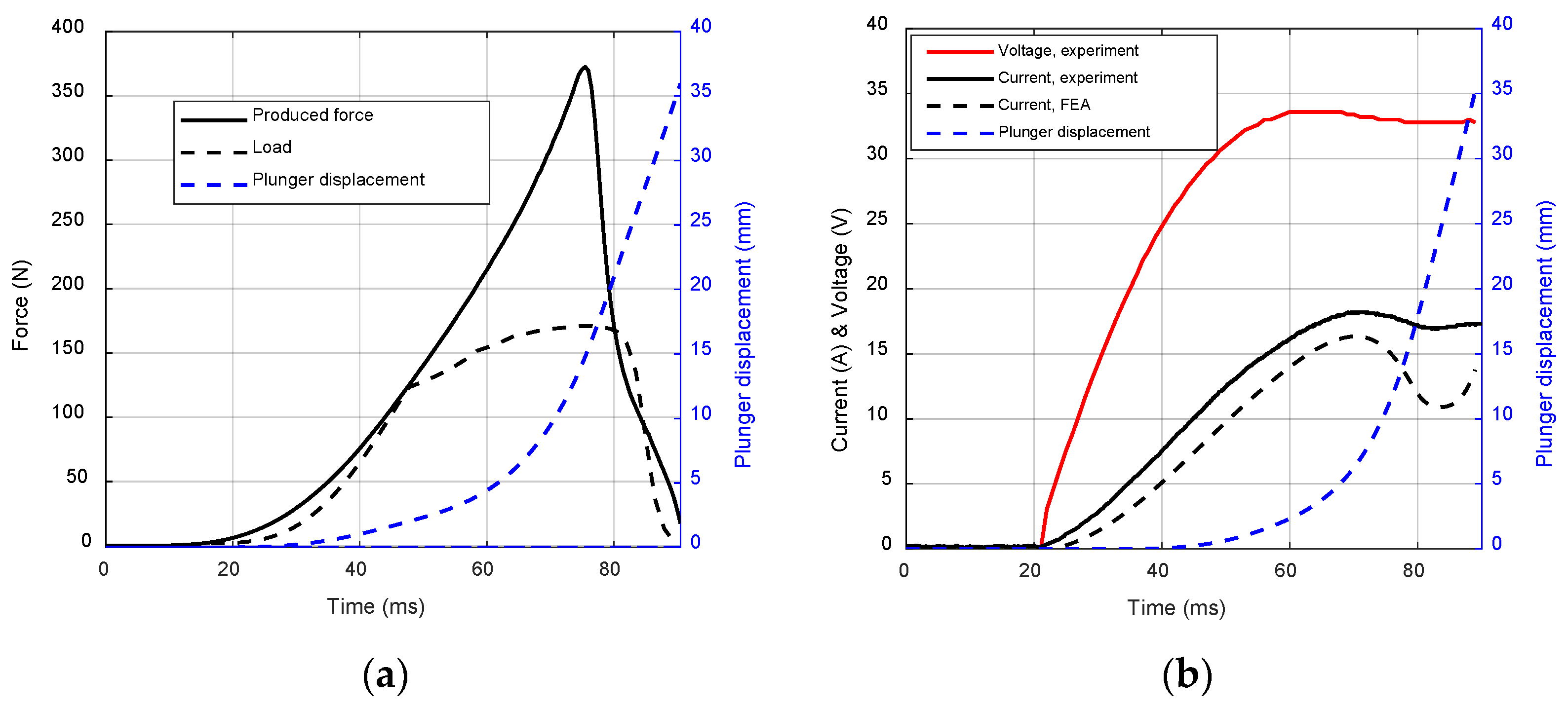
During the disconnection transient, the force developed by the electromagnetic device is recorded and compared against the permanent magnets’ pulling force (i.e., load force), as reported in
Figure 12a and
Figure 13a. For the sake of completeness, the plunger displacement over time is also shown. The developed force is enough to overcome the permanent magnets’ pulling force, as well as the friction force ensuring the accomplishment of the disconnection function in a time span of approximately 100 ms and 130 ms for Actuator 1 and Actuator 2, respectively. Being collected in the most challenging working conditions, these results prove that the designed disconnection actuators are able to interrupt the torque transmission, minimizing the risk of failure propagation.
For both of the disconnection actuators, current and voltage trends during the disconnection transient are given in
Figure 12b and
Figure 13b. It is noteworthy to point out that, for a brief period of time, the current flowing through the coil is higher than the expected value, i.e., 15 A. The exceeding current is ascribable to (1) the electrical transient taking place within the coil and (2) the higher friction force. Due to the short application time, the exceeding current does not represent a threat from a thermal perspective (i.e., the thermal constant of the coil is significatively greater than the overcurrent time). Furthermore, the electric power demanded to fulfill the disconnection function is relatively low, and in a practical application it could be delivered by a battery energy storage system.
6. Conclusions
The design procedure of two disconnection actuators meant to prevent failure propagation and ensure safe disconnection between rotating shafts was presented. Apart from briefly discussing the disconnection actuator architecture (i.e., coaxial magnetic coupling linked to the electromagnetic device), the benefit of contactless torque transmission was highlighted, which in turn enables lower maintenance costs and more effective torque transmission. These advantages make the designed disconnection actuators potential and valid alternatives to mechanical clutches. Additionally, the twofold design reflects the versatility of a disconnection actuator, which can be adopted in either high-speed or high-torque applications.
Throughout the design procedure, particular focus was given to electromagnetic device optimization, since it is responsible for the disconnection function. On the one hand, the radius of the coaxial magnetic coupling inner rotor was found to be a key parameter for sizing the electromagnetic device, because its dimensions depend on the plunger radius. On the other hand, the geometrical parameters that play a crucial role in the disconnection force developed by the electromagnetic device were identified as (1) the airgap thickness, (2) the slot opening length (), and (3) the slot opening location ( and ). Since the minimum airgap thickness (i.e., 2 mm) is constrained by mechanical reason, the slot opening length () and its location ( and ) were the candidates for the trade-off optimization. Therefore, a fully parametrized model of the electromagnetic device was built and two trade-off analyses (individually varying, in turn, and the ÷ pair) were performed relying on 2D finite element simulations.
The design stage was followed by the prototyping and testing of the disconnection actuators through a dedicated test bench. The experimental findings proved the disconnection capability of the designed actuators in the worst-case scenario, and the disconnection was accomplished in 100 ÷ 130 ms employing a relatively low electric power.


