Article

Torque Increase Strategy for Induction Motor in the Field-Weakening Region Based on Model Predictive Control

1
College of Information Engineering, Henan University of Science and Technology, Luoyang 471023, China
2
China Railway Engineering Equipment Group Co., Ltd., Zhengzhou 450016, China
*
Author to whom correspondence should be addressed.
Actuators 2023, 12(10), 395; https://doi.org/10.3390/act12100395
Submission received: 11 September 2023 / Revised: 19 October 2023 / Accepted: 20 October 2023 / Published: 22 October 2023
(This article belongs to the Special Issue Applications of Intelligent Control in Actuators Systems)

Abstract

:
In the field-weakening region, the traditional field-weakening method for induction motor drives based on model predictive control (MPC) is to take a no-load operation as the premise and adjust the flux reference in the cost function proportional to the inverse of the rotor speed, which leads to poor torque output. This paper presents a novel field-weakening method for IM drives based on MPC. Considering the induction motor field-weakening limiting conditions and according to the speed adaptive field-weakening strategy with a voltage closed-loop, the speed adaptive field-weakening controllers were designed to optimize the references of the excitation current and torque current. In the rotor field-orientation d–q coordinate system, the stator flux amplitude and torque reference values were optimized by the optimal distribution current. Then, according to the dead-beat control principle, they were converted into an equivalent stator flux vector reference. Moreover, the stator voltage vector reference can be obtained. For an induction motor fed by a three-level neutral point clamped (3L-NPC) inverter, the cost function was constructed by combining all the constraints, including the voltage vector, the neutral potential balance, and the switching frequency. In this way, the high-performance field-weakening operation for the induction motor based on a model predictive control can be realized. The simulation and experiment results show that the proposed method can increase the torque output by 22% in the field-weakening region; at the same time, the steady characteristics and the dynamic response performance can be maintained well.

1. Introduction

Induction motors (IMs) have been widely used in high-power modern industries due to their large capacity, simple structure, and wide speed range [1,2,3]. The 3L-NPC inverter is more suitable for high-power medium-voltage drives than a two-level inverter because of the low voltage stress of the power device, low voltage change rate, and lower harmonic voltage content [4,5]. MPC has the advantages of strong robustness, a fast dynamic response, and easy inclusion of nonlinearities [6,7]. With the improvement of microprocessor computing abilities, MPC has been widely used in the IM control field [8,9]. Moreover, because of its natural multivariable control, it is easier for MPC to constrain the neutral point potential unbalance of 3L-NPC inverters [10]. In order to achieve a high-performance control of IM, it is necessary to study motor drive control schemes based on MPC.
In order to extend the IM upper speed as much as possible with limited DC-link voltage, it is necessary to adopt the appropriate field-weakening strategy. The maximum output voltage of the inverter, the maximum current, and the maximum slip frequency of the IM are the three constraints that limit the torque output in the field-weakening region of the IM [11]. Therefore, coordinating the distribution of the excitation current and torque current and achieving the maximum torque is the core challenge of the field-weakening strategy. Based on rotor field-oriented control (RFOC), with the premise of the precise voltage model, the field-weakening strategy in Literature [12] aims to achieve the output torque and adjust the reference of the excitation current by looking up the table according to the reference speed, but it is still an open-loop control scheme and cannot guarantee the reference of the excitation current in the optimal state during the operation. The “1/ωr” field-weakening method is relatively simple to realize; when the motor speed exceeded the base speed, the flux level was set to an inverse proportion to the motor speed. However, the excitation current is too large to achieve the maximum torque output [13,14,15]. The voltage closed-loop field-weakening strategy is one of the most effective methods; it adjusts the field-weakening depth of the system by setting the output voltage of the voltage closed-loop field-weakening controller, and it has the advantages of a high voltage utilization ratio of the DC bus, low parameter sensitivity, and large torque output in the field-weakening region [16,17]. However, it is difficult to design the parameters of the field-weakening controller introduced into the control system, and the debugging work is complicated.
As for the field-weakening strategy for IM drives based on MPC, most of the current studies have not fully considered the operation of the field-weakening region. The traditional field-weakening method is to adjust the flux amplitude reference and torque reference to the inverse of the rotor speed. This method is easy to implement, but the torque reference does not take into account the extreme torque reference limit of different field weakening regions, which is only roughly reduced, and the optimal voltage vector cannot be selected, resulting in poor torque output. The method in Literature [18] adjusts the references of stator flux amplitude and torque in a manner of the inverse ratio of the speed in the constant power region. In order to increase the torque output in the constant voltage region, the maximum torque reference is limited as the value that makes the angle between the stator flux vector and rotor flux vector should not exceed 45°. However, the stator flux amplitude reference is still adjusted in the conventional way, which ignores the stator voltage on the premise of a no-load condition. It will lead to the excitation current reference being too large when the system is loaded, and the maximum torque output cannot be achieved. In Literature [19], under the condition of RFOC, the equation of the state of the rotor flux was discretized, and the ideal d-axis current reference was obtained by designing a field-weakening controller based on MPC; the control effect was good, and the system was relatively stable. However, the performance of this method depends heavily on the parameter setting of the inner current loop, so it is not easy to implement in engineering.
This paper proposes a novel field-weakening strategy for IM drives based on MPC. Firstly, the references of the excitation current and torque current are allocated by the voltage closed-loop speed adaptive field-weakening controller. In the d–q coordinate system with rotor flux orientation, the reference of the stator flux amplitude is calculated with the excitation current, and the reference of the torque current is determined by considering the maximum current and maximum slip frequency limits, and then the torque reference is calculated. Finally, based on the principle of dead-beat flux torque control, the torque and flux references are converted into an equivalent stator flux vector reference; moreover, the voltage vector reference is obtained. Compared with the traditional method, the proposed method has the following advantages: It optimizes the references, which improves the cost function and the torque output of the motor in the field-weakening region; There is no need to adjust the parameters of the inner current loop, and the dynamic response is fast. It is easy to realize nonlinear multivariable control, such as by reducing the switching frequency of the inverter. To realize the high-performance control of the induction motor in the field-weakening region, based on the 3L-NPC inverter, the cost function is constructed to constrain the voltage vector, neutral point potential, and switching frequency. The proposed strategy is verified by simulation and experiment.
The proposed field-weakening strategy for IM drives based on MPC has the following features:
(1)
The stator flux amplitude reference is optimal in the field-weakening region. This is achieved by the optimal excitation current reference, which is allocated optimally by the voltage closed-loop speed adaptive field-weakening controller.
(2)
The torque reference is optimal in the field-weakening region. This is achieved by the optimal torque current reference, which is limited by the maximum current of IM in the constant torque region and constant power region and limited by the maximum slip frequency of IM in the constant voltage region.
(3)
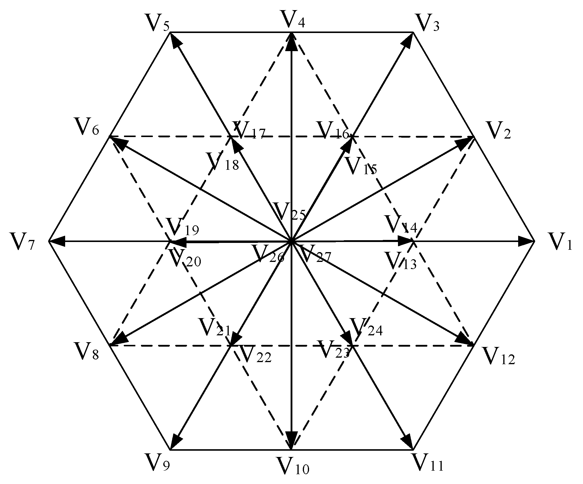
On the premise of a stable operation, the torque output of IM is the maximum that can be reached in the field-weakening region. This is achieved by the proper selection of voltage vectors because of the optimal references in the cost function.

2. Modeling and Analysis

In this paper, the stator current i s and the stator flux ψ s in the stationary reference frame are chosen as state variables, and the state-space model of the IM can be expressed in Equation (1):
d x d t = A x + B u
where, x = [ i s ψ s ] T , is the state variable; u = u s , is the stator voltage vector; the system matrix A and input matrix B are defined as in Equation (2).
{ A = [ λ ( R s L r + R r L s ) + j ω r λ ( R r j L r ω r ) R s 0 ] B = [ λ L r 1 ] , λ = 1 L s L r L m 2
where, R s is the stator resistance; R r is the rotor resistance; L s is the stator inductance; L r is the rotor inductance; L m is the mutual inductance; ω r is the electrical rotor speed; j is the imaginary unit.
To achieve higher accuracy, the mathematical model of IM is discretized by Heun’s method [20,21]. After discretization, it can be expressed in Equation (3):
{ x p k + 1 = x k + T s c [ A x k + B u k ] x k + 1 = x p k + 1 + T s c 2 A [ x p k + 1 x k ]
where, T s c is the control period; x k is the state variable at (k)th instant; x p k + 1 is the predictor-corrector of state vector; x k + 1 is the predicted vector of stator current and stator flux at (k + 1)th instant. The rotor flux at (k + 1)th instant can be computed from stator flux ψ s k + 1 and current i s k + 1 via Equation (4):
ψ r k + 1 = L r L m ψ s k + 1 1 λ L m i s k + 1
and the electromagnetic torque can be predicted via Equation (5):
T e k + 1 = 3 2 n P λ L m | ψ s k + 1 | * | ψ r k + 1 | * s i n θ s r
where, np is the number of pole pairs and θ s r is the angle between rotor flux and stator flux. In the RFOC-based IM drives, the IM voltage equation can be expressed as follows:
{ u s d = R s i s d + σ L s p i s d ω e σ L s i s q + L m L r p ψ r u s q = R s i s q + σ L s p i s q + ω e σ L s i s d + L m L r p ω e ψ r
where, ωe is the synchronous frequency; p is the differential operator, and σ is the leakage factor, σ = 1 L m 2 L s L r .
When the motor is in a high-speed steady state, the differential terms of flux and current are zero, and the voltage drop of stator resistance is negligible. Therefore, the voltage equation of an IM in a high-speed steady state can be simplified as follows:
{ u s d = ω e σ L s i s q u s q = ω e L s i s d
Moreover, i s q = u s d ω e σ L s , i s d = u s q ω e L s . The maximum current limit can be expressed as: i s d 2 + i s q 2 i s , m a x 2 .
To make the IM run stably in the field-weakening region, the slip frequency of the motor should be less than the maximum slip frequency. The maximum slip frequency during stable operation of the IM can be expressed as follows:
ω s l , m a x = 1 σ T r
where, T r is the electromagnetic time constant of the rotor, T r = L r R r .
The slip frequency limit can be expressed in voltage form or current form in Equation (9):
{ | u s d | u s , m a x 2 σ i s q i s d
Considering the constraints of maximum voltage and current, to output maximum torque, the voltage form field-weakening control equation of the induction motor in the stator voltage coordinate system can be expressed as follows:
{ u s d 2 + u s q 2 u s , m a x 2 ( u s d ω e σ L s ) 2 + ( u s q ω e L s ) 2 i s , m a x 2 | u s d | u s , m a x 2
According to Equation (10), the optimal voltage vector trajectory of the induction motor field-weakening operation can be drawn as in Figure 1.
As shown in Figure 1, in the synchronous d–q frame, the voltage limit is a fixed circle, while the current limit is an ellipse. The current limit ellipse increases with increasing rotor speed. In the constant torque region, the stator voltage trajectory is OA. When entering the constant power region, the operating point moves from A along the voltage limit circle to B. The optimal voltage vector trajectory in the constant voltage region should satisfy u s d = u s q = u s , m a x / 2 , namely, point B. The IM must satisfy the maximum voltage and maximum current limit when running in any speed region.

3. Optimization of Flux and Torque Reference for MPC

In the traditional field-weakening strategy for induction motor drives based on MPC, the inverse proportion of rotor speed method is adopted to adjust the flux amplitude reference and torque reference; this rough reference adjustment method makes it difficult to ensure that the IM has the best torque performance in the high-speed field-weakening region. In this paper, the references in the cost function are optimized based on the voltage closed-loop speed adaptive field-weakening control strategy.

3.1. Voltage Closed-Loop Field-Weakening Control Scheme

The system diagram of the voltage closed-loop speed adaptive field-weakening control scheme is shown in Figure 2 [22,23].
When u s q * is smaller than u s q , r e f * , the field-weakening controller PI-1 outputs i s d * . At this time, the torque current limit is ( i s , m a x * ) 2 - ( i s d * ) 2 , the motor runs in the constant torque region. With the continuous rise of the rotor speed, the torque current is only limited by the maximum current of the motor. When u s q * ( u s , m a x ) 2 - ( u s d * ) 2 , PI-1 starts to desaturate, the excitation current decreases, and the torque current increases. With the continuous rise of the rotor speed, the d-axis component of the stator voltage in the constant power region increases continuously, and the q-axis component of the stator voltage decreases continuously. The motor drive system gradually approaches the steady-state operating point, and the limiting amplitude of the torque current is still ( i s , m a x * ) 2 - ( i s d * ) 2 . When | u s d * | u s , m a x 2 , the motor enters the constant voltage region, PI-2 begins to work. At this time, the limit of maximum slip frequency on current takes precedence over the limit of maximum motor current, to ensure the motor runs at a stable point, namely u s d = u s q = u s m a x 2 , i s d = σ i s q .

3.2. Design of Field-Weakening Controller

The voltage closed-loop speed adaptive field-weakening strategy is based on RFOC; its excitation current and torque current are assigned by the field-weakening controller, then the d- and q-axis currents in the field-weakening region are decoupled by the complex vector current controller, and the d–q-axis current closed-loop control structure is constructed to make the current controller output the voltage reference u s d * and u s q * .
The IM drive based on MPC does not have the complex vector current controller, but in order to obtain the optimal distribution of d- and q-axis current references, this paper designs the field-weakening controller based on the complete field-weakening control structure. Then, it optimizes the stator flux amplitude reference and torque reference. The feedback inputs of PI-1 and PI-2 of the field-weakening controller are obtained by the optimal voltage complex vector, which makes the cost function minimum.
Based on the complete field-weakening control structure, the transfer function of the speed adaptive field-weakening controller PI-1 is set as Equation (11):
G v 1 ( s ) = K p v 1 ( 1 + K i v 1 s )
In the field-weakening region, the transfer function of the simplified q-axis voltage closed-loop control structure is as follows:
G p 1 ( s ) = K p c ω e s + K p c L s
where, ω e = ω s l + ω r , ω s l is the slip frequency. According to the low-frequency correction method, the system response is corrected, and the PI parameters design criteria of the field-weakening controller PI-1 can be obtained via Equation (13):
{ K i v 1 = ( 0.1 - 0.2 ) ω b 1 * K p v 1 = ( ω b 1 * σ ω c * ) 2 + 1 L s ω e
where, ω b 1 * is the expected bandwidth of the q-axis voltage closed loop, which should be less than the expected bandwidth of the current loop ω c * .
The transfer function of the speed adaptive field-weakening controller PI-2 can be obtained as follows:
G v 2 ( s ) = K p v 2 ( 1 + K i v 2 s )
In the field-weakening region, the transfer function of the simplified d-axis voltage closed-loop control structure is as follows:
G p 2 ( s ) = K p c ω e s + K p c σ L s
The system response is corrected according to the low-frequency correction method, and the PI parameters design criteria of the field-weakening controller PI-2 can be obtained via Equation (16):
{ K i v 2 = ( 0.1 - 0.2 ) ω b 2 * K p v 2 = ( ω b 2 * ω c * ) 2 + 1 σ L s ω e
where, ω b 2 * is the expected bandwidth of the d-axis voltage closed loop, which should be less than the expected bandwidth of the current loop ω c * .

3.3. Reference Optimization

After the above analysis, the diagram of the proposed field-weakening scheme for IM drives based on MPC is shown in Figure 3.
The voltage closed-loop speed adaptive field-weakening controller realizes the optimal distribution of excitation current and torque current references in the high-speed field-weakening region. In the d–q coordinate system of rotor field orientation, the stator flux amplitude reference and torque reference in the cost function are optimized by the optimal distribution current. The rotor flux amplitude reference can be obtained from Equation (17):
ψ r * = L m T r s + 1 i s d *
To obtain the stator flux amplitude reference, the spatial position angle of the rotor flux is calculated by Equation (18).
θ = ( ω s l + ω r ) d t
The relation between stator flux and rotor flux can be expressed as follows:
d ψ r d t + ( λ L s R r - j ω r ) ψ r = λ L m R r ψ s
In the steady state, Equation (19) can be simplified, and the stator flux amplitude reference can be expressed in Equation (20):
ψ s * = λ L s R r + j ω s l λ L m R r ψ r *
By Equation (20), the stator flux amplitude reference can be calculated.
The torque reference is calculated by Equation (21). Where, i s q * is the speed of the closed-loop PI controller’s output i s q , P I * , which is limited by the field-weakening controller PI-2 (constraint of maximum slip frequency) and the maximum current of the motor.
T e * = n p L m L r i s q * ψ r
where, ψ r is the rotor flux amplitude of the induction motor. In the constant torque region, the stator flux amplitude reference is set to the rated flux. The torque current limit is ( i s , m a x * ) 2 - ( i s d * ) 2 , and the maximum torque reference is n p L m L r ψ r ( i s , m a x * ) 2 - ( i s d * ) 2 . In the constant power region and constant voltage region, PI-1 starts to desaturate; the decreasing in i s d * lead to the decreasing in the stator flux amplitude reference, and in the constant power region, the torque current limit is still ( i s , m a x * ) 2 - ( i s d * ) 2 , and the maximum torque reference is unchanged. In the constant voltage region, PI-2 begins to work, the torque current limit changes to i s d * σ , and the maximum torque reference is n p L m L r ψ r i s d * σ , ensures that the motor can output the maximum torque under the premise of stable operation.
The reference of the stator flux amplitude depends on the reference of the excitation current, and the magnitude of the excitation current depends on the field-weakening depth. On the premise of a stable operation of the motor, the torque current is the maximum that can be reached in every operation region. Therefore, the field-weakening strategy for IM drives based on MPC proposed in this paper can adjust the references in the cost function to the optimum, thus improving the torque output.

4. IM Drives Based on MPC with Proposed Field-Weakening Scheme

Figure 4 shows the diagram of the IM speed regulation system with the proposed field-weakening method based on the model predictive flux control, including voltage closed-loop speed adaptive field-weakening controller, references optimization, references equivalent conversion, cost function, full-order observer, etc.
For the 3L-NPC inverter topology, different switching states Sa, Sb, and Sc make each phase of the motor connected to the positive (P), neutral (O), and negative (N) terminals on the DC bus. In this work, “2” represents “P”, “1” represents “O”, and “0” represents “N” in turn. The 3L-NPC inverter has 27 switching states, corresponding to 27 space voltage vectors, whose spatial voltage vector distribution is shown in Figure 5.
All 27 spatial voltage vectors in Figure 5 can be divided into large vectors (LVVs), medium vectors (MVVs), small vectors (SVVs), and zero vectors (ZVVs). The traditional IM drives based on MPC need to enumerate all 27 voltage vectors and calculate the stator flux and torque when different voltage vectors are applied. In order to realize smooth vector switching in both line and phase voltage, the pre-defined switching table (type II) in Literature [18] is adopted. Moreover, the number of candidate voltage vectors is reduced, and the real-time performance is improved.
Model predictive flux control takes the stator flux vector as the control target and converts the torque reference and the stator flux amplitude reference into an equivalent stator flux vector reference based on the flux-torque dead-beat control principle [24]. When the induction motor is in operation, to make the stator flux reach its reference in the next control period, the amplitude of the new stator flux vector reference is set as ψ * , ψ * = | ψ s * | . In order to make the electromagnetic torque reach its reference in the next control period, the angle between the rotor flux and stator flux at the next instant can be calculated by Equation (22).
θ s r = a r c s i n ( T e * 3 2 n p λ L m | ψ r k + 1 | ψ * )
In Equation (22), the rotor flux at the (k + 1)th instant is calculated by Equation (4). The angle of the new stator flux vector reference can be obtained by Equation (23).
ψ s * = ψ r k + 1 + θ s r
Therefore, the new stator flux vector reference can be expressed in Equation (24):
ψ s * = ψ * e x p ( j ψ s * )
Based on the dead-beat principle, the stator flux vector is assumed to reach its reference at the end of the control period, and the reference of the stator voltage vector is calculated according to the voltage Equation (25).
u s * = R s i s k + 1 + ψ s * ψ s k + 1 T s c
In order to balance the neutral point potential of the 3L-NPC inverter and reduce the switching frequency of the device, it is necessary to design an appropriate cost function to constrain it. The neutral point potential deviation Δ U n e u is defined as the voltage difference between two capacitors on the DC bus of the 3L-NPC inverter, which can be expressed in Equation (26).
Δ U n e u = U c 1 U c 2
The neutral point voltage deviation at the (k + 1)th instant can be predicted according to the neutral point voltage deviation at the (k)th instant and the selected switching state via Equation (27).
Δ U n e u k + 1 = - T s c C [ | S a k - 1 | | S b k - 1 | | S c k - 1 | ] [ i a k i b k i c k ] + Δ U n e u k
where, i a k , i b k , i c k is the three-phase stator current at the (k)th instant; C = C 1 = C 2 is the capacitance values of the capacitors on the DC side.
We defined n s w as the number of switching transitions between the switching states to be applied and the switching states in the last control period, which can be expressed in Equation (28):
n s w = x = { a , b , c } | S x k + 1 S x k |
Summarily, the cost function can be expressed in Equation (29):
J = | u s * v k + 1 | + K n e u | Δ U n e u k + 1 | 2 + K n n s w + I o p
where, v k + 1 is the candidate voltage vectors that can be generated by the 3L-NPC inverter, which is determined by the applied switching states Sa, Sb, and Sc. Kneu and Kn are weighting factors for the neutral point voltage balance and average switching frequency, respectively, which can be adjusted and attenuated or enhanced as needed. Iop is the overcurrent protection item, which can be expressed as Equation (30):
I o p = { 0 i f | i s k + 1 | > i m a x i f | i s k + 1 | i m a x
During implementation, when | i s k + 1 | > i m a x , we set the Iop to a large enough value.

5. Simulation and Experiment

5.1. Simulation Results

In order to verify the effectiveness of the reference optimization scheme based on the voltage closed-loop speed adaptive field-weakening principle, the simulation model of IM drives based on MPC was established in Matlab/Simulink. The three-phase squirrel-cage asynchronous motor was chosen as the induction motor used in the simulation. The parameters used in the simulation model are shown in Table 1, and the sampling frequency is 10 kHz. In the simulation, the field-weakening control strategy described in reference [18] was used as a comparison, and the PI controller parameters of the two models’ speed closed-loops were the same: Kp = 0.8 and Ki = 10.
In this paper, the described MPC does not control the current directly; it may cause excessive starting current and trigger overcurrent protection when starting. To reduce the starting current, the method of DC preexcitation is adopted in this paper. When the stator flux amplitude and the stator current amplitude of the motor are less than 90% of the rated, a fixed voltage vector is applied to the inverter, otherwise zero vector is applied. In this way, the flux is established inside the motor before starting, which can increase the starting torque and reduces the starting current effectively.
The starting response from standstill to 6000 rpm with the field-weakening strategy in [18] is shown in Figure 6. From top to bottom, the curves are rotor speed, electromagnetic torque, stator flux amplitude, and one-phase stator current of the IM.
With the preexcitation technique, the stator flux is first established, which can be seen in the third picture of Figure 6. The stator current does not exceed the limit, and the motor starts smoothly. Without load, the motor reaches the 400% base speed at 2.6 s. At 3.5 s, the load increased to 2.8 N∙m, and the rotor speed decreased slightly, which can no longer be maintained at 6000 rpm. At 6 s, the load increases to 3.5 N∙m, and the speed decreases significantly. At 10 s, the load is reduced to 1 N∙m, and the motor accelerates again to 6000 rpm.
The references are optimized by adopting the voltage closed-loop speed adaptive field-weakening strategy. The rotor speed, electromagnetic torque, stator flux amplitude, and one-phase stator current are shown in Figure 7. With the preexcitation technique, the motor starts without load and accelerates smoothly to 6000 rpm at 2 s. When the load increases to 2.8 N∙m, 3.5 N∙m, and decreases to 1 N∙m, the rotor speed and torque can follow the references well, and the motor can run smoothly. Compared with the field-weakening control algorithm in Literature [18], the load output of the motor is increased by 25%, and the dynamic response is faster.
As shown in Figure 8a, with optimization, the stator flux amplitude reference decreases faster than without optimization. When the load is applied, the stator flux amplitude is increased to obtain large electromagnetic torque while the rotor speed does not decrease. On the contrary, to increase the torque output, without reference optimization, the rotor speed must be reduced to obtain a larger flux. The comparison of torque reference is shown in Figure 8b; based on the voltage closed-loop speed adaptive field-weakening strategy, the proposed algorithm can adjust the stator flux amplitude reference and torque reference optimally to realize the maximum torque output of the induction motor.
Figure 9 shows that the excitation current and torque current are constant in the rated speed region. In the constant power region, the excitation current decreases, and the torque current increases. In the constant voltage region, the torque current decreases with the decrease in the excitation current. When the rotor speed reaches the 400% base speed, the system exits the field-weakening state, and the torque current decreases rapidly. Therefore, both methods can realize the field-weakening operation for the IM drives based on MPC. However, we can see that the dynamic process of the proposed algorithm is faster than the algorithm in Literature [18]. When the IM is loaded at 6000 rpm, the proposed algorithm in this paper can adjust the torque reference and stator flux amplitude reference optimally and then achieve the optimum distribution of the excitation current and torque current. Therefore, the rotor speed could maintain the 6000 rpm with load increase and decrease.
As shown in Figure 10, in the constant power region and constant voltage region, the proposed algorithm has a larger electromagnetic torque output than the algorithm in Literature [18]. The rotor speed curve shown in Figure 10 verifies because of the optimum distribution of the excitation current and torque current, the maximum torque output is realized, and the accelerating process is more rapid. When the rotor speed reaches 400% base speed, the motor enters a steady state. Figure 10 shows that the torque ripple of both algorithms is almost identical. While the motor is loaded, with the algorithm in Literature [18], the torque output has not reached the requirement. When the load decreases to 1 N∙m, the rotor speed accelerates again to 6000 rpm, but the torque curve shows that the max torque output is small. The rotor speed and electromagnetic torque curves verify the increase in torque output with the proposed algorithm.

5.2. Experimental Results

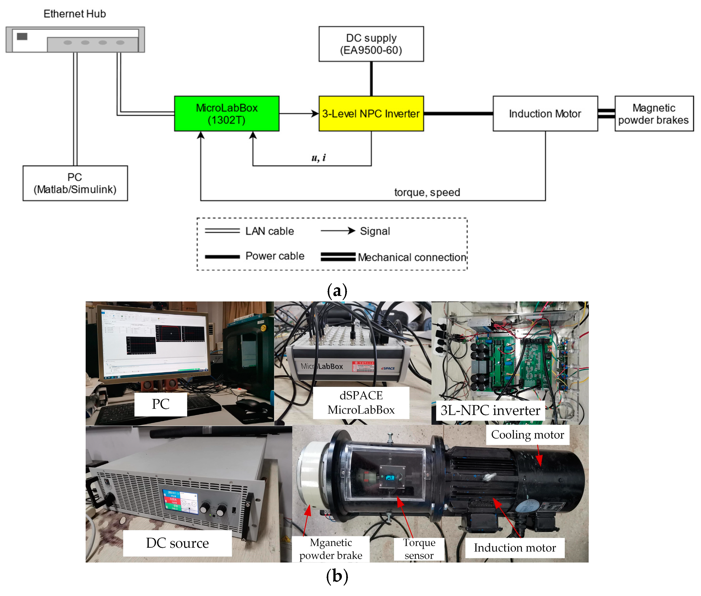
5.2.1. Hardware Setup Scheme

In order to verify the effectiveness of the proposed field-weakening strategy in real-time scenarios, a 3L-NPC inverter-driven IM model predictive control speed regulation experimental platform was implemented on the laboratory scale. The scheme of the test platform is shown in Figure 11a.
Regarding the energy flow, the DC power supply is connected to the DC link of the inverter, and the AC output of the inverter is connected to the three-phase induction motor. A magnetic powder brake is used as the motor loading device. In order to achieve closed-loop control, the motor speed and torque are detected by the photoelectric encoder and torque sensor, respectively, and the voltage and current signals are detected by the Hall sensor, all of which are fed back to the controller. A MicroLabBox produced by dSPACE is used as the main controller to run the algorithm. After judging the complementary logic and dead zone of the hardware with CPLD, the multi-channel PWM wave produced by the controller is output to the driver board. If the conditions are not met, the PWM signal will be blocked.

5.2.2. Hardware Components Description

The devices used for the real-time experiment are shown in Figure 11b. The programmable DC power supply from EA (EA-PSI 9500-60) is used here. The YXPHM-TP310b-I 3-level NPC inverter is used here, including the main circuit, driver board, signal sampling, conditioning board, etc. The YVF2-100L1-4 motor is a three-phase squirrel-cage asynchronous motor produced by Shanghai YiFang Motor. A MicroLabBox (1302T) from dSPACE is used as the controller; the sampling frequency is set to 10 kHz to execute the control strategy. For safety reasons, the DC-bus voltage is reduced to half of the rated value, and then the speed of 3000 rpm is four times the base speed (750 rpm) in the test. The weighting factors of Kmid and Kn are adjusted to 20 and 10. The experimental data are recorded using a PC, and the results are visualized as experimental waveforms with Matlab2021a.

5.2.3. Results Analysis

Figure 12 shows the step acceleration process from the standstill to 400% base speed with halved DC-bus voltage (Literature [18]). From top to bottom, the curves in Figure 12 are rotor speed, one-phase stator current, stator flux amplitude, line-to-line voltage, and DC-bus voltage. The motor accelerates quickly with constant stator flux amplitude when the rotor speed is below the base speed. Above the base speed, the stator flux amplitude decreases inversely with the rotor speed. When the motor is running at 3000 rpm without load, due to the small capacitance of the inverter, the stator current is distorted, which will affect the torque output of the motor to some extent.
In the experiment, a magnetic powder brake was used as the loading device. Due to its nonlinearity and the influence of temperature rise, it is difficult to precisely control the output braking force during operation. Different from the ideal step load in simulation, the control signal needs to be increased slowly after applying a rough load torque until the output torque of the motor is exceeded, and then the motor speed decreases.
Figure 13 shows the response of the motor at 3000 rpm with an increasing load. It can be seen that the load is applied at 2.5 s, the speed decreases slightly, and after a dynamic process, the speed rises to 3000 rpm again. As the applied load continues to slowly increase, the rotor speed decreases again and cannot remain at the required speed of 3000 rpm at 8.45 s; at this time, the load is about 1.5 N∙m. That is to say, the output torque at 3000 rpm is less than 1.5 N∙m. To evaluate the output torque at 400% base speed, we take the average torque from 8 s to 8.4 s as the actual torque output, as shown in Figure 13b; the average load torque is 1.37 N∙m. The speed will decrease when the load is greater than 1.37 N∙m, and the max stable torque output at 3000 rpm is also at this level.
The acceleration process from 0 to 400% base speed without load with our proposed strategy is shown in Figure 14. The plot arrangement is similar to Figure 12, from top to bottom; the curves in Figure 14 are the rotor speed, one-phase stator current, stator flux amplitude, line-to-line voltage, and DC-bus voltage, respectively. It can be seen that the proposed field-weakening strategy also has a fast dynamic speed response; the speed can increase from 0 to 3000 rpm in 1.6 s. It is not neglectable that the current becomes distorted when the speed approaches 3000 rpm, which is similar to the method in [18], which lies in the difference between the mathematical model and the actual device. However, the distortion is slightly better than that in Figure 12.
Figure 15 shows the speed and torque responses of the motor at the required speed of 3000 rpm with an increasing load with the proposed method. The torque loading is the same as in Figure 13; the load is applied at 2.5 s and then increases slowly until the speed cannot be maintained at the required speed of 3000 rpm. During the process, the speed response is shown in Figure 15a, and the torque change is shown in Figure 15b. From the response, we can see that the speed did not decrease significantly when the load was applied first, which means that the proposed method has stronger load disturbance resistance. As the applied load continues to slowly increase, the speed can also remain at the required 3000 rpm; when the torque increases to above 1.8 N∙m at 15.5 s, the rotor speed decreases. If the load is further increasing, the speed will decrease drastically, which means the system cannot operate. We also take the average torque between the interval of 15.05 s to 15.45 s as the max stable output torque, as shown in Figure 15b; the average load torque is 1.68 N∙m. The effects of the two methods are shown in Table 2.
Comparing the results in Table 2, the torque output can be increased by 22% at a 400% base speed. Though it is slightly less than the simulation improvement (25%), the improvement is also significant. From Figure 13 and Figure 15, we find that the current has distortion with the proposed method and the method in [18], which may lie in the parameter mismatch caused by the temperature rise of the motor during operation, sampling errors inherent in electrical signals, etc.

6. Conclusions

In this paper, a novel field-weakening scheme for induction motor drives based on MPC has been proposed. In order to achieve the maximum torque output in the field-weakening region, a voltage closed-loop speed adaptive field-weakening controller is designed to assign the references of the excitation current and torque current optimally. In the rotor field-oriented d–q coordinate system, the stator flux amplitude reference and torque reference are optimized by the reference current. In the field-weakening region, the references in the cost function can be adjusted optimally for the field-weakening operation. By converting them into an equivalent stator flux vector reference according to the dead-beat control principle, the stator voltage reference is obtained. With the optimization of the reference, the torque output can be improved. The simulation and experiment results show that the proposed strategy can significantly improve the torque output of the induction motor in the field-weakening region, and the steady characteristics and dynamic response performance can be maintained well.

Author Contributions

Conceptualization, J.H. and P.Z.; Formal analysis, J.H. and S.L.; Investigation, S.L.; Methodology, J.H. and S.L.; Resources, P.Z.; Supervision, J.H.; Validation, Y.W.; Visualization, Y.W.; Writing—original draft, S.L.; Writing—review and editing, J.H., P.Z. and Y.W. All authors have read and agreed to the published version of the manuscript.

Funding

This research was funded by the National Nature Science Foundation of China, grant number U1504617.

Data Availability Statement

No new data were created or analyzed in this study. Data sharing is not applicable to this article.

Conflicts of Interest

The authors declare no conflict of interest.

References

  1. Tousizadeh, M.; Che, H.S.; Selvaraj, J.; Rahim, N.A.; Ooi, B.-T. Performance Comparison of Fault-Tolerant Three-Phase Induction Motor Drives Considering Current and Voltage Limits. IEEE Trans. Ind. Electron. 2019, 66, 2639–2648. [Google Scholar] [CrossRef]
  2. Karkkainen, H.; Aarniovuori, L.; Niemela, M.; Pyrhonen, J. Converter-Fed Induction Motor Efficiency: Practical Applicability of IEC Methods. IEEE Ind. Electron. Mag. 2017, 11, 45–57. [Google Scholar] [CrossRef]
  3. Steffen, T.; Rafaq, M.S.; Midgley, W. Comparing Different Resonant Control Approaches for Torque Ripple Minimisation in Electric Machines. Actuators 2022, 11, 349. [Google Scholar] [CrossRef]
  4. Kouro, S.; Cortes, P.; Vargas, R.; Ammann, U.; Rodriguez, J. Model Predictive Control—A Simple and Powerful Method to Control Power Converters. IEEE Trans. Ind. Electron. 2009, 56, 1826–1838. [Google Scholar] [CrossRef]
  5. Vazquez, S.; Rodriguez, J.; Rivera, M.; Franquelo, L.G.; Norambuena, M. Model Predictive Control for Power Converters and Drives: Advances and Trends. IEEE Trans. Ind. Electron. 2017, 64, 935–947. [Google Scholar] [CrossRef]
  6. Zhang, Y.C.; Zhu, J.G.; Zhao, Z.M.; Xu, W.; Dorrell, D.G. An Improved Direct Torque Control for Three-Level Inverter-Fed Induction Motor Sensorless Drive. IEEE Trans. Power Electron. 2012, 27, 1502–1513. [Google Scholar] [CrossRef]
  7. Hu, H.; Yao, W.; Lu, Z. Design and Implementation of Three-Level Space Vector PWM IP Core for FPGAs. IEEE Trans. Power Electron. 2007, 22, 2234–2244. [Google Scholar] [CrossRef]
  8. Froisy, B. Model Predictive Control: Past, Present and Future. ISA Trans. 1994, 33, 235–243. [Google Scholar] [CrossRef]
  9. Rodriguez, J.; Kazmierkowski, M.P.; Espinoza, J.R.; Zanchetta, P.; Abu-Rub, H.; Young, H.A.; Rojas, C.A. State of the Art of Finite Control Set Model Predictive Control in Power Electronics. IEEE Trans. Ind. Inf. 2013, 9, 1003–1016. [Google Scholar] [CrossRef]
  10. Akter, M.P.; Lu, D.D.-C.; Zhu, J. Model Predictive Controlled Three-Level Active-Neutral-Point-Clamped Inverter with Improved Computational Speed and Stability, and Balanced DC-Link Voltages. In Proceedings of the 2017 IEEE 3rd International Future Energy Electronics Conference and ECCE Asia (IFEEC 2017—ECCE Asia), Kaohsiung, Taiwan, 3–7 June 2017. [Google Scholar]
  11. Sepulchre, R.; Devos, T.; Jadot, F.; Malrait, F. Antiwindup Design for Induction Motor Control in the Field Weakening Domain. IEEE Trans. Contr. Syst. Technol. 2013, 21, 52–66. [Google Scholar] [CrossRef]
  12. Kim, S.-H.; Sul, S.-K. Voltage Control Strategy for Maximum Torque Operation of an Induction Machine in the Field Weakening Region. IEEE Trans. Ind. Electron. 1997, 44, 512–518. [Google Scholar]
  13. Xu, X.; Novotny, D.W. Selection of the Flux Reference for Induction Machine Drives in the Field Weakening Region. IEEE Trans. Ind. Appl. 1992, 28, 1353–1358. [Google Scholar] [CrossRef]
  14. Nisha, G.K.; Lakaparampil, Z.V.; Ushakumari, S. Torque Capability Improvement of Sensorless FOC Induction Machine in Field Weakening for Propulsion Purposes. J. Electr. Syst. Inf. Technol. 2017, 4, 173–184. [Google Scholar]
  15. Xie, P.; Li, G.; Xie, F.; Hu, C.; Qi, X. Research on Field-Weakening Control of Induction Motor Based on Torque Current Component of the Voltage Closed-Loop. In Proceedings of the 2015 IEEE 10th Conference on Industrial Electronics and Applications (ICIEA), Auckland, New Zealand, 15–17 June 2015. [Google Scholar]
  16. Sahoo, S.K.; Bhattachrya, T. Field weakening strategy for a vector controlled induction motor drive near the six-step mode of operation. IEEE Trans. Power Electron. 2016, 31, 3043–3051. [Google Scholar] [CrossRef]
  17. Wang, B.; Zhang, J.; Yu, Y.; Zhang, X.; Xu, D. Unified Complex Vector Field-Weakening Control for Induction Motor High-Speed Drives. IEEE Trans. Power Electron. 2021, 36, 7000–7011. [Google Scholar] [CrossRef]
  18. Zhang, Y.; Bai, Y.; Yang, H.; Zhang, B. Low Switching Frequency Model Predictive Control of Three-Level Inverter-Fed IM Drives with Speed-Sensorless and Field-Weakening Operations. IEEE Trans. Ind. Electron. 2019, 66, 4262–4272. [Google Scholar] [CrossRef]
  19. Su, J.; Gao, R.; Husain, I. Model Predictive Control Based Field-Weakening Strategy for Traction EV Used Induction Motor. In Proceedings of the 2016 IEEE Energy Conversion Congress and Exposition (ECCE), Milwaukee, WI, USA, 18–22 September 2016. [Google Scholar]
  20. Zhang, Y.; Bai, Y.; Yang, H. A Universal Multiple-Vector-Based Model Predictive Control of Induction Motor Drives. IEEE Trans. Power Electron. 2018, 33, 6957–6969. [Google Scholar] [CrossRef]
  21. Zhang, Y.; Yang, H. Two-Vector-Based Model Predictive Torque Control without Weighting Factors for Induction Motor Drives. IEEE Trans. Power Electron. 2016, 31, 1381–1390. [Google Scholar] [CrossRef]
  22. Zhang, X.; Wang, B.; Yu, Y.; Zhang, J.; Dong, J.; Xu, D. Analysis and Optimization of Current Dynamic Control in Induction Motor Field-Weakening Region. IEEE Trans. Power Electron. 2020, 35, 8860–8866. [Google Scholar] [CrossRef]
  23. Wang, B.; Zhang, J.; Yu, Y.; Zhang, X.; Xu, D. Speed Adaptive Voltage Closed-Loop Field-Weakening Control for Induction Motor Drives. In Proceedings of the 2019 IEEE Energy Conversion Congress and Exposition (ECCE), Baltimore, MD, USA, 29 September–3 October 2019. [Google Scholar]
  24. Zhang, Y.; Yang, H.; Xia, B. Model-Predictive Control of Induction Motor Drives: Torque Control Versus Flux Control. IEEE Trans. Ind. Appl. 2016, 52, 4050–4060. [Google Scholar] [CrossRef]
Figure 1. Optimal voltage vector trajectory.
Actuators 12 00395 g001
Figure 2. Diagram of voltage closed-loop field-weakening control scheme.
Actuators 12 00395 g002
Figure 3. Diagram of voltage closed-loop field-weakening scheme for IM drives based on MPC.
Actuators 12 00395 g003
Figure 4. Diagram of induction motor field-weakening control system based on MPC.
Actuators 12 00395 g004
Figure 5. The Space vector of the 3L-NPC inverter.
Actuators 12 00395 g005
Figure 6. Starting and loading response with the field-weakening algorithm (Literature [18]).
Actuators 12 00395 g006
Figure 7. Starting and loading responses with the proposed field-weakening algorithm.
Actuators 12 00395 g007
Figure 8. Flux and torque references: (a) stator flux amplitude reference; (b) torque reference.
Actuators 12 00395 g008
Figure 9. Comparison of the two methods’ excitation (d) and torque (q) current: (a) dq current without optimization; (b) dq current with optimization.
Actuators 12 00395 g009
Figure 10. Comparison of rotor speed and electromagnetic torque.
Actuators 12 00395 g010
Figure 11. Experimental platform of the induction motor control system. (a) Scheme of the experimental platform; (b) Photography of the main devices.
Actuators 12 00395 g011
Figure 12. Acceleration process from 0 rpm to 3000 rpm (400% base speed) (Literature [18]).
Actuators 12 00395 g012
Figure 13. The load is applied suddenly and slowly increases: (a) rotor speed; (b) electromagnetic torque (Literature [18]).
Actuators 12 00395 g013
Figure 14. Acceleration process from 0 rpm to 3000 rpm (400% base speed) (proposed strategy).
Actuators 12 00395 g014
Figure 15. The load is applied suddenly and slowly increases: (a) rotor speed; (b) electromagnetic torque (Proposed strategy).
Actuators 12 00395 g015
Table 1. Parameters of the simulation model.
ParametersValues
DC-bus voltage, Udc540 V
Rotational inertia, J0.02 kg·m2
Rated voltage, Un380 V
Rated power, Pn2.2 kW
Rated frequency, fn50 Hz
Rated torque, Tn14 N·m
Rated speed, n1500 rpm
Number of pole pairs, np2
Stator resistance, Rs2.8 Ω
Rotor resistance, Rr2.5 Ω
Stator inductance, Ls0.22423 H
Rotor inductance, Lr0.22423 H
Mutual inductance, Lm0.2124 H
DC-link capacitors, C1, C2680 μF
Weighting factor for neutral point balance, Kneu35
Weighting factor for switching frequency, Kn50
Table 2. Torque output performances with proposed field-weakening strategy and that in Literature [18].
Control StrategyMax Torque Output
(400% Base Speed)
Load Disturbance Resistance
Strategy in Literature [18]1.37 N∙mHigh
Proposed strategy1.68 N∙mAverage
Disclaimer/Publisher’s Note: The statements, opinions and data contained in all publications are solely those of the individual author(s) and contributor(s) and not of MDPI and/or the editor(s). MDPI and/or the editor(s) disclaim responsibility for any injury to people or property resulting from any ideas, methods, instructions or products referred to in the content.

