Article

Design, Modeling, Testing, and Control of a Novel Fully Flexure-Based Displacement Reduction Mechanism Driven by Voice Coil Motor

School of Mechanical and Automotive Engineering, Shanghai University of Engineering Science, Shanghai 201620, China
*
Author to whom correspondence should be addressed.
Actuators 2022, 11(8), 228; https://doi.org/10.3390/act11080228
Submission received: 17 July 2022 / Revised: 31 July 2022 / Accepted: 5 August 2022 / Published: 8 August 2022

Abstract

:
This paper presents a flexure-based displacement reduction mechanism driven by a voice coil motor to improve the motion resolution and eliminate the hysteresis nonlinearity of the traditional piezo-actuated micropositioning/nanopositioning stages. The mechanism is composed of three groups of compound bridge-type displacement reduction mechanisms, which adopt distributed-compliance rectangular beams to reduce the concentration of stress and improve the dynamic performance of the mechanism. The symmetrical distribution of the structure can eliminate the parasitic displacement of the mechanism and avoid the bending moment and lateral stress applied to the voice coil motor. Firstly, the analytical model of the mechanism is obtained by the stiffness matrix method. The theoretical displacement reduction ratio, input stiffness, and natural frequency of the displacement reduction mechanism are obtained by solving the analytical model. Then, through the static analysis and modal analysis of the mechanism with the Ansys software, the accuracy of the analytical model is verified, and the experimental prototype is also constructed for performance tests. The results show that the maximum stroke of the mechanism is 197.43 μm with motion resolution of 40 nm. The natural frequency is 291 Hz, and the input stiffness is 28.50 N/mm. Finally, the trajectory tracking experiment is carried out to verify the positioning performance of the mechanism. The experimental results show that the designed feedback controller has good stability, and the introduction of the feedforward controller and disturbance observer can greatly reduce the tracking errors.

1. Introduction

Microdisplacement actuators such as piezoelectric actuators (PZTs) and voice coil motors (VCMs) are widely used in the fields of micromanipulation/nanomanipulation, scanning probe microscopy, and ultra-precision machining owing to their high stiffness, high resolution, fast response, and nanopositioning accuracy [1,2,3,4]. However, the PZT has only a small stroke of tens of microns and nonlinear characteristics such as hysteresis and creep [5,6]. Therefore, in order to achieve larger output displacement, flexure-based displacement amplification mechanisms are often used to amplify the stroke of the PZT [6]. As a kind of electromagnetic actuator, the VCM has been increasingly used in the large-stroke micropositioning/nanopositioning stages [7]. For instance, micropositioning/nanopositioning stages with millimeter or even centimeter ranges were reported in [8,9,10,11,12,13,14]. However, with the increase of the travel range, the motion resolution and accuracy of the micropositioning stage actuated by the VCM will also decline. Therefore, opposite the amplified PZTs, the motion resolution of the long-range electromagnetic actuators such as the VCM can be improved by employing a displacement reduction mechanism, which can also solve the hysteresis problem of the PZTs.
In the previous literature, many works have systematically studied the design and modeling of the flexure-based displacement amplification mechanism [15,16,17,18], but few the reduction mechanism. Theoretically, the displacement amplification mechanism can achieve the purpose of displacement reduction by exchanging the input and output positions. However, there will be several problems after exchanging. Firstly, the specifications to be considered in designing the amplification mechanism are obviously different from those in designing the reduction mechanism [19,20,21]. Different from the displacement amplification mechanism driven by the PZT, the displacement reduction mechanism changes the macrodisplacement generated by the VCM into microdisplacement. Therefore, the stiffness design and the macro-/micro-scale transmission process of the displacement reduction mechanism should be deeply studied. Several flexure-based displacement reducers have been designed in the past few years. For instance, Wu and Chen proposed a bridge differential displacement reducer with a reduction ratio of 100 by combining two bridge-type flexure mechanisms [22]. However, this kind of displacement reducer with a high reduction ratio is generally suitable for the PZT. The large reduction ratio achieved by combining multiple reducers will also lead to energy transmission inefficiency [19,20,21].
Therefore, the focus of this paper is to propose a novel fully flexure-based displacement reduction mechanism. Through the displacement reduction mechanism driven by the large-stroke VCM, the millimeter-level output displacement of the motor is transmitted to the end-effector to achieve micron-level output. The mechanism is composed of three groups of compound bridge-type displacement reduction mechanisms. The distributed-compliance rectangular beams used in the mechanism not only reduce the concentration of stress, but also improve the dynamic performance of the mechanism. The symmetrical distribution structure can eliminate the parasitic displacement of the mechanism along the X direction and avoid the bending moments and lateral stress applied to the VCM. In terms of stroke range, through reasonable structural design, the displacement reduction mechanism driven by the VCM has a stroke equivalent to the conventional displacement amplification mechanism driven by the PZT. More importantly, the design avoids various nonlinear characteristics such as hysteresis and creep caused by the PZT in principle. The rest of this paper is organized as follows: In Section 3, based on the stiffness matrix method, the analytical model of the mechanism is established. Section 4 verifies the good static performance of the mechanism through finite element analysis and experiment tests. In Section 5, the position control is carried out to verify the good trajectory tracking performance of the mechanism. Finally, the conclusion is given in Section 6. The main contribution and innovation points of this work are that the displacement reduction mechanism is successfully used to reduce the displacement of the VCM to improve its motion resolution and effectively eliminate the hysteresis nonlinearity of the traditional piezo-actuated nanopositioning stage.

2. Design of Displacement Reduction Mechanism

The displacement reduction mechanism proposed in this paper is a distributed-compliance flexure mechanism, and its structure and working principle are shown in Figure 1. The mechanism is composed of three groups of compound bridge-type displacement reduction mechanisms. The two groups of bridge-type mechanisms on both sides are secondary reduction mechanisms, and the one in the middle is a primary reduction mechanism. After the two-stage displacement reduction of the mechanism, the millimeter-level input displacement of Rigid Body 3 produced by the VCM can be significantly reduced and transmitted to Rigid Body 4 to achieve micron-level output displacement. Instead of the commonly used concentrated notch flexure hinge in the traditional flexure mechanism, the proposed mechanism adopts 12 distributed-compliance rectangular beams, which not only reduce the concentration of stress, but also improve the dynamic performance of the mechanism. This is because, in the deformation process, the stress generated on the notch flexure hinge will become very large, which will make the flexure hinge very fragile in this state. Moreover, the traditional lumped-compliance bridge-type mechanism, using the notch flexure hinges, will introduce rigid bodies with large mass in its arms, which has great weakness for the resonant frequency of the mechanism. Therefore, the bending deformation of rectangular beams in the proposed mechanism makes the stress distribution of the whole flexure mechanism relatively uniform, rather than concentrated in specific areas. This characteristic ensures that the mechanism has better performance and longer service life in dynamic applications. Moreover, the mechanism adopts a symmetrical distribution structure to reduce the input displacement with two stages, which can also eliminate the parasitic displacement of the mechanism in the X direction, avoiding the bending moments and lateral stress applied to the VCM, and effectively eliminate the friction between the mover and the stator in the VCM. In addition, it is worth mentioning that the design can avoid various nonlinear characteristics such as hysteresis and creep caused by the PZT in principle and improve the stability and positioning accuracy.

3. Analytical Model

As shown in Figure 1a, the displacement reduction mechanism is mainly composed of six rigid bodies, of which Rigid Bodies 5 and 6 are used as frames, and the other four are movable rigid bodies. To obtain the dynamic equation of the mechanism, the three degrees of freedom (3-DOFs) q i = x i y i θ z i of each movable rigid body are taken as the generalized coordinates of the mechanism.
q = q 1 q 2 q 4 T
Therefore, the multi-DOF vibration differential equation of the displacement reduction mechanism is expressed in matrix form as
M q ¨ + K q = F
M = diag ( M 1 M 2 M 3 M 4 )
The stiffness matrix K is
K = K ˜ 11 K ˜ 12 K ˜ 13 K ˜ 14 K ˜ 21 K ˜ 22 K ˜ 23 K ˜ 24 K ˜ 31 K ˜ 32 K ˜ 33 K ˜ 34 K ˜ 41 K ˜ 42 K ˜ 43 K ˜ 44
The external force vector F is
F = [ F 1 F 2 F 3 F 4 ] T
In Equation (3), the form of the ith element of the mass matrix M is M i = d i a g ( m x i m y i J z i ) , where ( m x i , m y i ) are the mass components of the ith rigid body in the X and Y directions, respectively. J z i is the mass moment of inertia of the ith rigid body in the Z-axis direction. In Equation (5), the ith element of external force vector F is F i = d i a g ( F x i F y i M z i ) . When force vector F is applied, the relationship between the applied force and displacement is obtained by the following formula:
q = K 1 F
Based on the observation method in vibration theory, each element in the stiffness matrix of K can be obtained. This method can be described as the main diagonal element K ˜ i i of the stiffness matrix being the sum of the stiffness of the elastic elements connected with the ith rigid body, and the non-diagonal element K ˜ i j is the sum of the stiffness of the elastic elements connected with the ith and jth rigid bodies. Therefore, in Equation (4), the elements of the equivalent stiffness matrix are
K ˜ i i = j = 1 n i J i j K i j J i j T
K ˜ i j = k = 1 n i j J i j k K i j k J j i k T , K ˜ j i = K ˜ i j T
J i j = 1 0 0 0 1 0 r y i j r x i j 1 cos θ i j sin θ i j 0 sin θ i j cos θ i j 0 0 0 1
H i j k = 1 0 0 0 1 0 h y i j k h x i j k 1
J i j k = 1 0 0 0 1 0 r y i j k r x i j k 1 cos θ i j k sin θ i j k 0 sin θ i j k cos θ i j k 0 0 0 1 , J j i k = 1 0 0 0 1 0 r y j i k r x i j k 1 cos θ j i k sin θ j i k 0 sin θ j i k cos θ j i k 0 0 0 1
In Equation (9), [ r x i j r y i j ] represents the coordinates of the vector O i O i j in the O i X Y Z coordinate system. θ i j represents the rotation angle of O i j X Y Z relative to the O i X Y Z coordinate system, as shown in Figure 2a. The expression method of Equation (11) is similar to that of Equation (9), as shown in Figure 2b. In addition, the stiffness matrices K i j and K i j k of the rectangular beam can be obtained by taking the inverse of the compliance matrix and expressed as
C i j = l E b t 0 0 0 4 l 3 E b t + 3 l 2 G b t 6 l E b t 3 0 6 l 2 E b t 3 12 l E b t 3
K i j = ( C i j ) 1
where E is the elastic modulus of the material and G is the shear modulus of the material.
According to the theory of vibration, the characteristic equation of the multi-DOF differential equation is obtained by solving Equation (3):
λ I M 1 K = 0
The natural frequencies of the mechanism are
f i = 1 2 π λ i , i = 1 , 2 , . . . , 12 .
Based on the analytical model of the mechanism, when the VCM applies force along the Y direction to Rigid Body 3, the motion and pose of the end-effector can be calculated by Equation (6). Therefore, the displacement reduction ratio and input stiffness of the mechanism can be expressed as
C = K 1 R r e d = u o u t / u i n = c 11 , 2 / c 2 , 2 K i n = 1 / c 2 , 2
Based on the analytical model, the structural parameters of the displacement reduction mechanism can be determined under certain constraints. In order to obtain the desired natural frequency and output displacement of the mechanism along the working direction, the size parameters of the mechanism need to be carefully adjusted, as shown in Figure 3. An appropriate safety level must be maintained, and the designing of the structures should be conducted in compliance with optimization procedures. Generally, the structural safety level can be measured with the application of a reliability index [23,24]. The maximum stress produced at the root of the stretched beam shall be less than the allowable stress. According to the known maximum continuous output force of the selected VCM (40 N) and the desired output displacement (200 μm), the structural parameters are carefully adjusted through the trial-and-error method with the assistance of the analytical model. The design parameters of the mechanism are shown in Table 1.

4. FEA and Experimental Verification

4.1. FEA Verification

In this section, the Ansys Workbench software is used for static and modal analysis of the mechanism to obtain its performances, including the displacement reduction ratio, input stiffness, and natural frequency. The three-dimensional (3D) model of the mechanism was established by the Solidworks software and imported into Ansys Workbench for static analysis. Aluminum alloy was selected as the model material, and its elastic modulus and Poisson ratio were 70 Gpa and 0.33, respectively. As shown in Figure 4, fixed constraints were applied to the two bolt holes at the bottom of the mechanism, and the VCM provides continuous driving force F = 40 N to act on the mechanism along the Y direction. Thus, the end-effector of the mechanism produces the reduced output displacement along the same direction. The static von Mises stress and the total deformation of the mechanism are shown in Figure 5.
The displacement reduction ratio and input stiffness are obtained by FEA:
R r e d = u o u t u i n , K i n = F u i n
where u i n and u o u t are the maximum input and output displacements calculated by the FEA results. F is the continuous thrust of the VCM in FEA.
It can be seen from the FEA results that the maximum input displacement of the mechanism is 1348.4 μm and the maximum output displacement is 184.35 μm. The displacement reduction ratio calculated by Equation (17) is 0.1367, and the input stiffness is 29.67 N/mm, which is basically consistent with the results of 0.1335 and 29.28 N/mm calculated by the analytical model, and the corresponding errors are 2.34% and 1.31%, respectively. Moreover, the maximum von Mises stress obtained from the FEA solution is 141.09 Mpa, which is far lower than the allowable stress of aluminum alloy 7075 (the yield strength is about 480 Mpa), indicating that the displacement reduction mechanism is always in the state of elastic deformation in the whole movement process. At the same time, to analyze the load capacity of the mechanism, a force of 40 N is applied to the end-effector along the working direction in the FEA model. It can be obtained that the displacement of the end-effector under the force is 24.35 μm, and then, the output stiffness of the mechanism is 164 N/mm, about 5.6-times the input stiffness, showing the high load capacity of the mechanism.
In addition, the first four vibration modes of the reduced mechanism are also obtained through FEA, as shown in Figure 6, and the natural frequencies corresponding to the first four modes of the mechanism are listed in Table 2. The results show that the first mode corresponds to the regular left–right swing of the four movable rigid bodies in the XOY plane. The second mode corresponds to the rotation around the fixed constraint in the ZOX plane. The third mode corresponds to the working mode of the mechanism, and the fourth mode corresponds to the irregular left–right swing of the four movable rigid bodies in the XOY plane, while the fourth-order natural frequency is much higher than the first three modes. In practical application, although the displacement reduction mechanism is assembled with the VCM, the stiffness of the VCM is infinite, and its mover is light in weight, which has little impact on the dynamic performance of the mechanism.

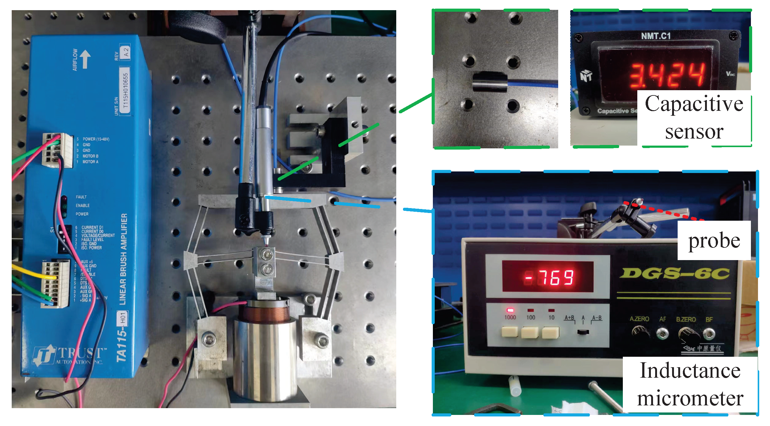
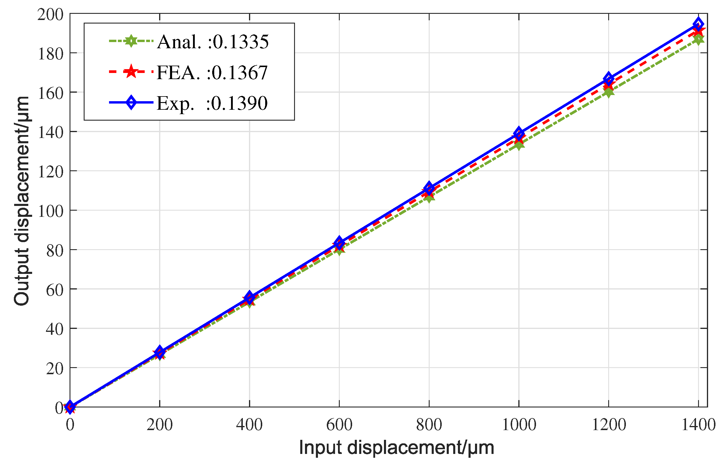
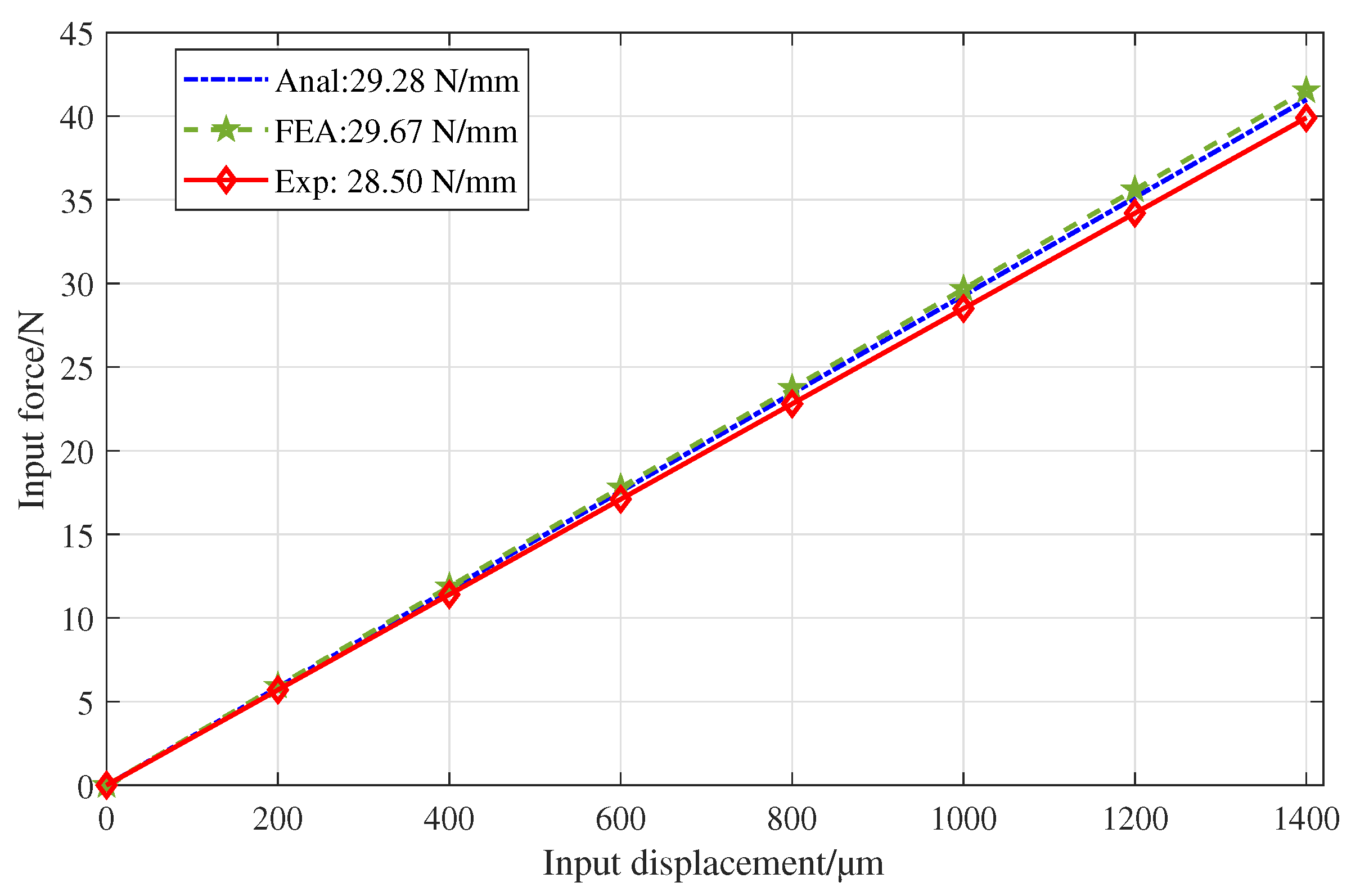
4.2. Performance Testing

To evaluate the performance of the mechanism and verify the accuracy of the analytical model, experimental setups were established as shown in Figure 7. The mechanism was processed by fine milling and wire cutting, and aluminum alloy 7075 was selected as the material of the mechanism to improve its structural strength. In the experimental test, the VCM (VCAR0070-0419-00A) was selected as the driver of the mechanism to generate the input force and displacement. The motor can provide continuous thrust of 40 N (corresponding drive voltage of 5.6 V). The force constant of the VCM was 17.7 N/A, and the maximum allowable current was 4 A. A capacitive displacement sensor (NMT.C1) with a resolution of 2.5 nm and a measuring range of 200 μm was used to measure the output displacement of the mechanism. An inductance micrometer (DGG-8Z) with a resolution 0.01 μm and a measuring range of 2 mm was used to measure the input displacement of the mechanism. Two displacement sensors are shown in Figure 8. In addition, the output voltage (0∼10 V) of the displacement sensor is collected by the data acquisition card (PCI-6251) equipped with 16-bit A/D and D/A converters, and the output voltage (−10 V∼10 V) of the data acquisition card is linearly converted into the driving current (−4 A∼+4 A) through the current linear amplifier (TA115) to drive the VCM.
Firstly, when the motor thrust gradually increased, the input and output displacements of the mechanism were detected simultaneously by two displacement sensors to obtain the maximum stroke and reduction ratio of the mechanism. The experimental setup is shown in Figure 8. The experimental test results of the mechanism are shown in Figure 9. Obviously, the maximum stroke of the mechanism is 197.43 μm when the driving voltage is about 5.6 V, corresponding to the driving current of 2.26 A and the driving force of 40 N. The good linear relationships between the input and output displacements and the control voltage show that the displacement reduction mechanism driven by the VCM does not have various nonlinear characteristics such as hysteresis and creep and has good positioning stability and accuracy. Meanwhile, according to the relationship between the input and output displacement, the reduction ratio of the mechanism is 0.1390. In Figure 10, the displacement reduction ratios calculated by the analytical model, FEA model, and experimental prototype are compared, and the results are in good agreement, indicating that the analytical model has high modeling accuracy.
To obtain the input stiffness of the mechanism, the inductive micrometer (DGC-8Z) and the force sensor (JLBS-MD of Jinnuo company) were combined at the input end of mechanism. The experimental setup is shown in Figure 7. The force sensor was placed between the VCM and the input rigid body. When the VCM pushes and pulls the input rigid body, the force sensor can read its output force, and the inductance micrometer is used to measure the input displacement. According to the relationship between the force and displacement, the input stiffness of the mechanism obtained from the testing result is 28.50 N/mm. The comparison of the input stiffness is given in three ways, as shown in Figure 11, and the results show good consistency.
To obtain the natural frequency along the working direction of the mechanism, the mechanism was separated from the VCM, and then, the impact load was applied to the end-effector of the mechanism along its working direction to make it vibrate freely. At the same time, the capacitive sensor was used to measure the vibration displacement of the mechanism to obtain the dynamic characteristics of the whole system. The data acquisition card collects the input time-domain vibration signals, which are then processed by the fast Fourier transform (FFT) to convert them into frequency-domain signals through the Labview software. The experimental test result of the mechanism is shown in Figure 12. It can be seen that the natural frequency of the mechanism is 291 Hz. The maximum error of the natural frequency among the analytical model, FEA model, and testing results is 9.84%. This difference is mainly attributed to the neglect of the influence of the flexure beams’ vibration kinetic energy on the dynamic performance in the analytical model.
Table 3 compares the reduction ratio, input stiffness K i n (N/mm), and natural frequency f m (Hz) of the displacement reduction mechanism, which were obtained from the analytical model, FEA, and experimental test. Taking the experimental results as a reference, the relative errors of the analytical model (Error1) and FEA (Error2) can be obtained, respectively. As can be seen from Table 3, the differences among the results of the analytical model, FEA, and the experimental test are less than 10%, indicating that the three results are in good agreement and the analytical model has high calculation accuracy.

5. Controller Design

In this section, the tracking performance of the mechanism is evaluated. Firstly, the dynamic parameters of the system are identified, and the nominal transfer function of the system is obtained. Then, a two-DOF controller consisting of feedback controller G c ( s ) and a dynamic inverse feedforward controller C f f ( s ) are used to control the position of the mechanism. The feedback controller is obtained by allocating the zero-pole distribution of the system using the root locus method. Finally, to meet the requirements of micropositioning/nanopositioning accuracy, an anti-interference controller based on a disturbance observer (DOB) was introduced to effectively suppress the interference. The control system diagram is shown in Figure 13.

5.1. Dynamic Model Identification

To obtain the dynamic model of the system, a semi-physical real-time simulation control system was established by using the PCI-6251 data acquisition card, Links-Box-02 embedded real-time simulator, and MATLAB/Simulink real-time simulation system software packages. The experimental setup of the control system is shown in Figure 14. The chirp signal with a sweep voltage amplitude of 0.1 V was selected as the driving input, and the frequency was changed linearly from 0.1 Hz to 1.0 kHz. The output displacement was collected by the capacitive contactless displacement sensor (NMT.C1). Using the system identification toolbox in MATLAB, the system nominal transfer function is obtained as
G n ( s ) = 8.472 × 10 4 s 2 + 141.4 s + 1.301 × 10 5
The input and output time-domain signals collected in the experiment were processed by the FFT, as shown in Figure 15. The frequency response of the experimental measurement results is plotted and compared with the Bode diagram of the identified transfer function. According to the formant peak, the natural frequency of the system is about 347 rad/s, which is different from the natural frequency of the flexure mechanism itself due to the electrical and control system of the VCM. At the same time, the identified system model fits well with the experimental results, which can accurately describe the dynamic characteristics of the whole system.

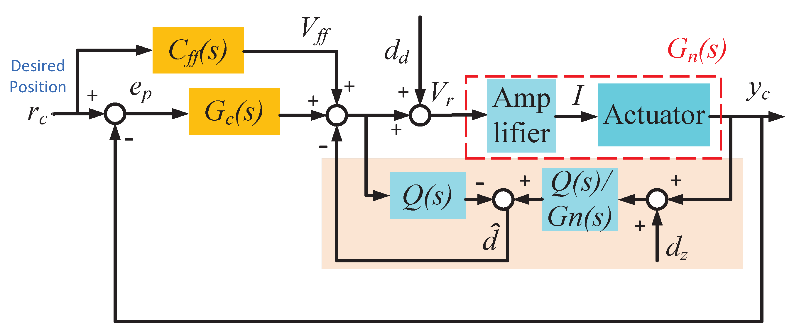
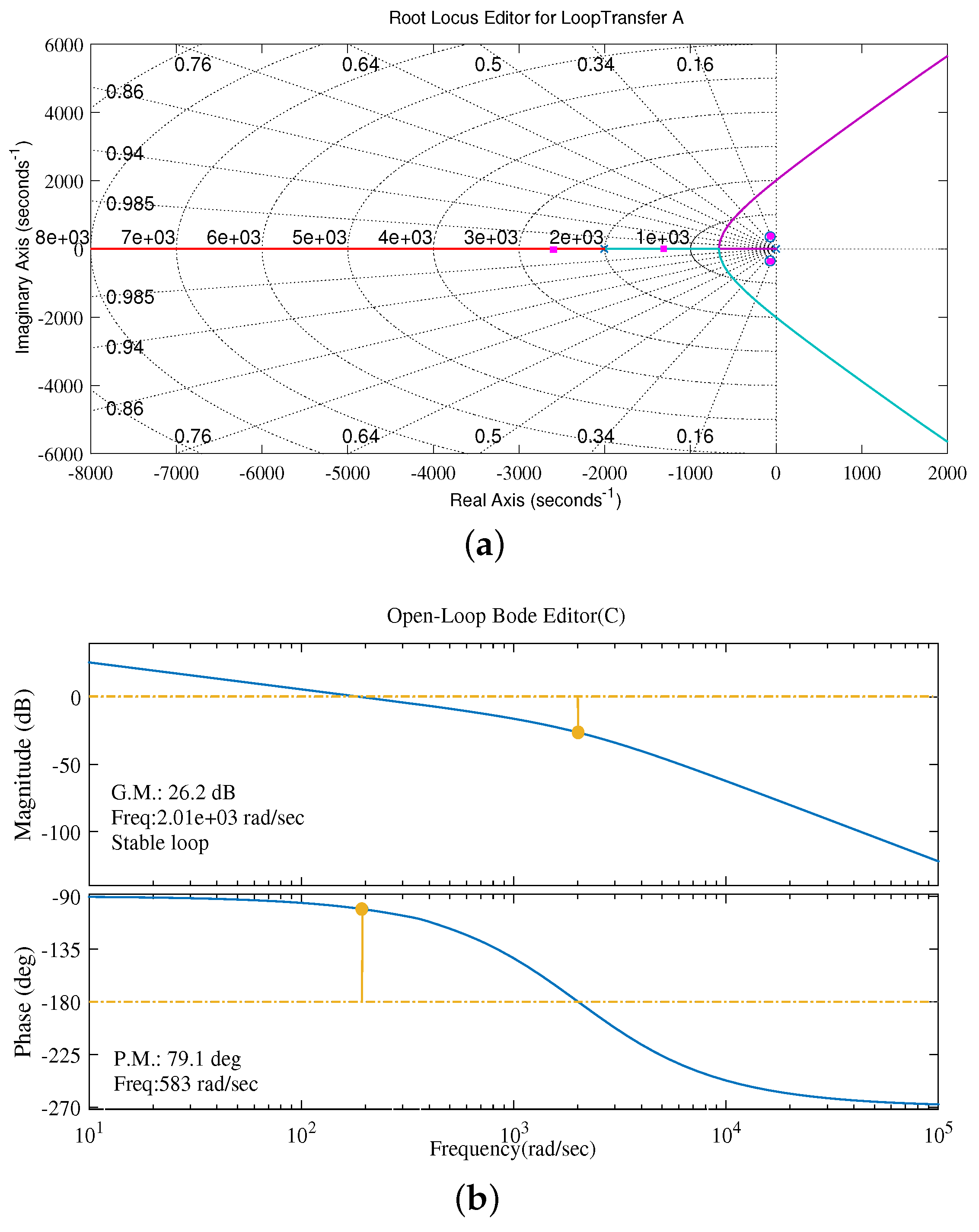
5.2. Design Process of Controller

In the system model of the flexure mechanism, there are two poles very close to the virtual axis, and the resonant mode has a low damping ratio of about 0.2. Mechanical vibration will be easily excited when moving at high speed. The low gain margin caused by low damping resonant mode causes large phase error, which affects the stability and the rapid response of the system. Therefore, in this paper, a high-performance feedback controller that can effectively suppress stage resonance and high-frequency noise disturbance was designed by using zero-pole placement and the root locus correction method. First, a new pole was placed at the origin to achieve zero steady-state error. In the system test, a pair of conjugate poles near the virtual axis may cause large-amplitude vibrations and make the system difficult to stabilize. To offset the influence of these poles, a pair of conjugate zeros was placed near them. Finally, to improve the response speed of the system, two poles were placed far away from the virtual axis. After correctly designing the poles, zeros, and gains of the controller, the system behavior was obtained, as shown in Figure 16. Finally, the transfer function of the designed controller is obtained as
G c ( s ) = 9437.1 × ( s 2 + 140.8 s + 1.293 × 10 5 ) s × ( s 2 + 4014 s + 4.208 × 10 6 )
After the feedback controller is added, the open loop Bode diagram of the system is shown in Figure 16b. The amplitude margin and phase margin of the system after correction are 26.2 dB and 79.1 , respectively. Obviously, the controlled system is stable with a large margin.
Due to the integral element of the feedback controller, the stage system is a type 1 system, which cannot track with zero steady-state error when it is a ramp signal. Feedforward compensation based on the system dynamics inverse is widely used in the position control of complex dynamic systems. A feedforward controller C f f ( s ) is designed as
C f f ( s ) = G n 1 ( s )
To test the motion resolution of the mechanism in the working direction, a staircase signal with a height of 125 nm was applied to the VCM, and the position tracking test was carried out by using the compound control methods of feedback control and dynamic inverse feedforward. A capacitive displacement sensor (NMT.C1) with a resolution of 2.5 nm and a measurement range of 200 μm was used to measure the output displacement of the mechanism. The output displacement curve in Figure 17 shows an about 40 nm peak-to-peak amplitude, meaning that the motion resolution of the mechanism can reach 40 nm in the working direction.

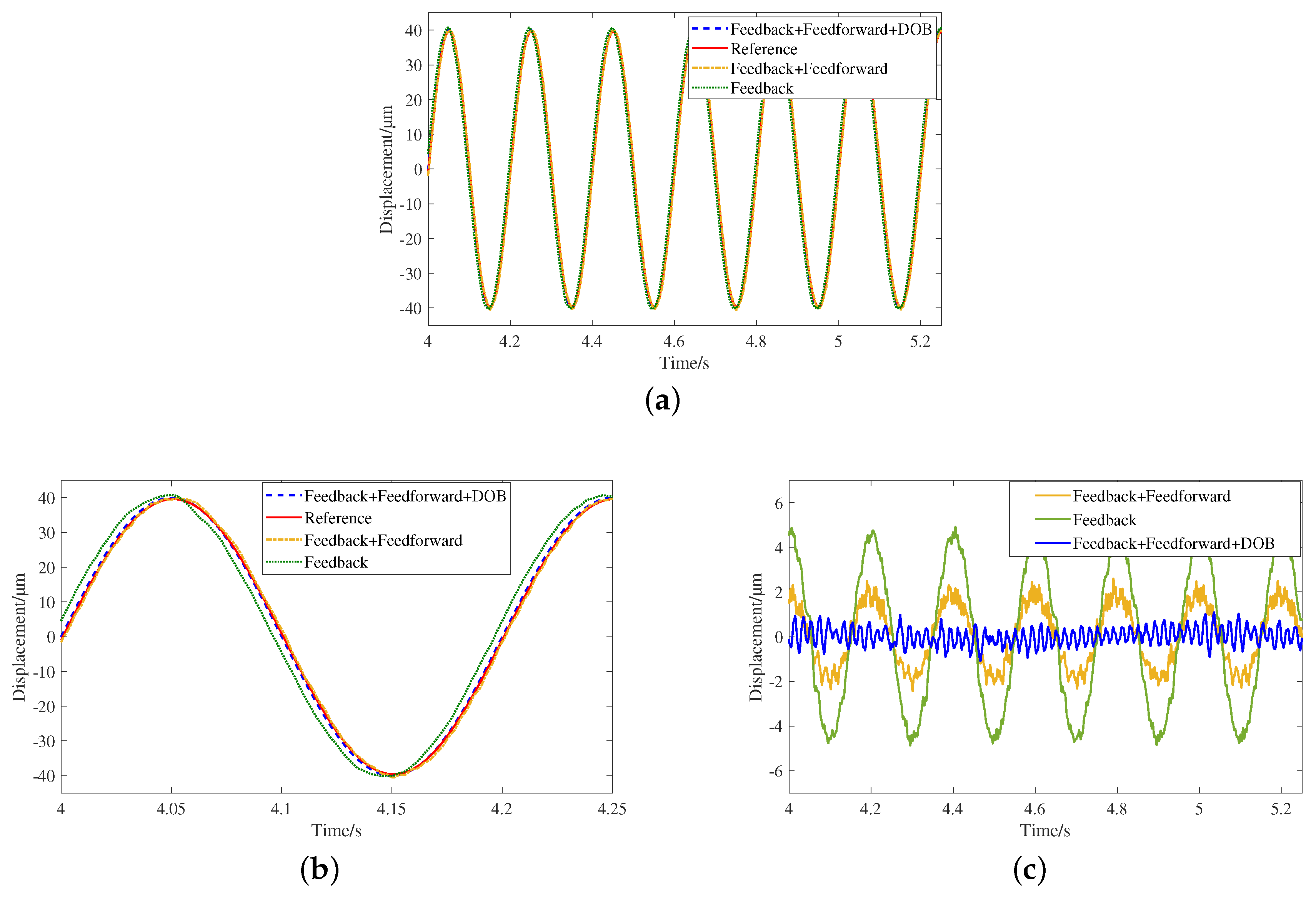
5.3. Disturbance Rejection

One problem of the VCM using Lorentz force to drive the low-stiffness-flexure mechanism is the low resonant frequency, which will be easily excited by disturbance and affect the positioning resolution of the system. In the positioning process of the mechanism, the main disturbances are the noise of current amplifier and DA converter, the VCM mover vibration, as well as the vibration of the isolation platform. The disturbance observer can unify the disturbances such as friction and model the uncertainty of the controlled object into equivalent disturbances, then estimate the equivalent disturbance by using the nominal inverse model of the controlled object and the input control value. For instance, Deng and Yao designed an extended state observer, which can estimate the unmeasurable velocity signal for the control of electrohydraulic servomechanisms [25]. Due to the simple structure and convenient parameter adjustment, the DOB has been widely used as a part of controller compensating for disturbances [26,27,28,29]. As shown in Figure 13, to obtain micro-/nano-level tracking performance, the disturbance observer (DOB) is introduced into the closed-loop negative feedback control loop to observe the equivalent disturbance d ^ , which can theoretically achieve the complete suppression of the disturbance. By designing low-pass filter Q ( s ) , the low-frequency disturbance can be observed effectively, and the high-frequency noise signal can be filtered effectively. Q ( s ) is expressed as
Q ( s ) = k = 0 M α k ( τ s ) k ( τ s + 1 ) N
where α k = N ! ( N k ) ! k ! is the coefficient, N is the order of the denominator, M is the order of the numerator, and N-M is the relative order. The value of the parameter determines the bandwidth of Q ( s ) . Considering the ability of the disturbance observer to suppress external disturbance and its sensitivity to measurement noise, τ = 0.001 was selected. Due to the order of Q ( s ) , the filter should not be too high, so N = 3 and M = 1 were selected.
To test the trajectory tracking effect of the designed control system, a sinusoidal signal with an amplitude of 2 V (corresponding to 40 μm displacement) and a frequency of 5 Hz was selected as the desired trajectory. The tracking performances of three controllers, Feedback, Feedback + Feedforward, and Feedback + Feedforward + DOB, were compared. The tracking results are shown in Figure 18. It can be seen from Figure 18b that Feedback control has a relatively large phase error compared with the other two control methods.
The trajectory tracking errors of the three control systems are shown in Figure 18c. The maximum tracking error peak-to-trough value (P-V) for the Feedback control is approximately ±4.98μm (12.38%). After adding Feedforward control, the error is reduced to ±2.60 μm (6.5%). When DOB anti-interference compensation is further added, the maximum tracking error of the designed control system is reduced to ±1.40 μm (3.5%), which is only 0.28-times that of Feedback control. The maximum tracking error (MTE) and root-mean-squared tracking error (RMSTE) of trajectory tracking are shown in Table 4. The MTE and RMSTE of the latter two control methods are less than 3 μm, indicating that the proposed reduction mechanism can achieve good tracking performance.

6. Conclusions

This paper presents a fully flexure displacement reduction mechanism, which is composed of three groups of compound bridge-type displacement reduction mechanisms to realize two-stage displacement reduction. Firstly, an analytical model for the predictions of the theoretical displacement reduction ratio, input stiffness, and natural frequency was derived based on the stiffness matrix method. Then, after determining the size of the mechanism based on the analytical model, the 3D model of the mechanism was established through SolidWorks and then imported into Ansys Workbench for FEA. The experimental tests were also carried out to validate the performances of the proposed displacement reduction mechanism. The motion range of 197.43 μm, the reduction ratio of 0.1369, the input stiffness of 28.50 N/mm, the motion resolution of 40 nm, and the natural frequency of 291 Hz were obtained from the experiment. The experimental test results were basically consistent with the analytical model and FEA model, and the maximum error was the error of the natural frequency, which was less than 10%. Finally, a two-DOF controller consisting of a feedback controller, a dynamic inverse feedforward controller combined with DOB anti-interference compensation was designed for the control of positioning stage. Excellent positioning and tracking performances were achieved, which verifies the effectiveness of the proposed displacement reduction mechanism and the designed controller. Our subsequent main work is to design a multi-DOF high-speed decoupled displacement reduction mechanism to improve the performance and application scope of the stage. In addition, taking this stage as a micro-stage to design a macro–micro dual-drive stage is also the focus of future research.

Author Contributions

Conceptualization, L.L. and Y.C.; methodology, L.L.; FEA and experiment tests, Y.C.; writing, Y.C. and L.L. All authors have read and agree to the published version of the manuscript.

Funding

This work was supported by the Natural Science Foundation of Shanghai (Grant No. 21ZR1426000), and the State Key Laboratory of Mechanical System and Vibration (Grant No. MSV202210).

Institutional Review Board Statement

Not applicable.

Informed Consent Statement

Not applicable.

Data Availability Statement

Not applicable.

Conflicts of Interest

The authors declare no conflict of interest.

References

  1. Lee, C.; Lee, J.W.; Ryu, S.G.; Oh, J.H. Optimum design of a large area, flexure based XYθ mask alignment stage for a 12-inch wafer using grey relation analysis. Robot. Comput. Integr. Manuf. 2019, 58, 109–119. [Google Scholar] [CrossRef]
  2. Zhu, W.L.; Yang, X.; Duan, F.; Zhu, Z.; Ju, B.F. Design and adaptive terminal sliding mode control of a fast tool servo system for diamond machining of freeform surfaces. IEEE Trans. Ind. Electron. 2017, 66, 4912–4922. [Google Scholar] [CrossRef]
  3. Xiao, R.; Xu, M.; Shao, S.; Tian, Z. Design and wide-bandwidth control of large aperture fast steering mirror with integrated-sensing unit. Mech. Syst. Signal Process. 2019, 126, 211–226. [Google Scholar] [CrossRef]
  4. Guo, D.; Nagel, W.S.; Clayton, G.M.; Leang, K.K. Spatial-temporal trajectory redesign for dual-stage nanopositioning systems with application in AFM. IEEE/ASME Trans. Mechatron. 2020, 25, 558–569. [Google Scholar] [CrossRef]
  5. Yang, C.; Li, C.; Zhao, J. A nonlinear charge controller with tunable precision for highly linear operation of piezoelectric stack actuators. IEEE Trans. Ind. Electron. 2017, 64, 8618–8625. [Google Scholar] [CrossRef]
  6. Tian, Y.; Cai, K.; Zhang, D.; Liu, X.; Wang, F.; Shirinzadeh, B. Development of a XYZ scanner for home-made atomic force microscope based on FPAA control. Mech. Syst. Signal Process. 2019, 131, 222–242. [Google Scholar] [CrossRef]
  7. Csencsics, E.; Schitter, G. Exploring the pareto fronts of actuation technologies for high performance mechatronic systems. IEEE/ASME Trans. Mechatron. 2020, 26, 1053–1063. [Google Scholar] [CrossRef]
  8. Rakuff, S.; Cuttino, J.F. Design and testing of a long-range, precision fast tool servo system for diamond turning. Precis. Eng. 2009, 33, 18–25. [Google Scholar] [CrossRef]
  9. Ito, S.; Troppmair, S.; Lindner, B.; Cigarini, F.; Schitter, G. Long-range fast nanopositioner using nonlinearities of hybrid reluctance actuator for energy efficiency. IEEE Trans. Ind. Electron. 2018, 66, 3051–3059. [Google Scholar] [CrossRef]
  10. Sun, L.; Chen, F.; Dong, W. A pzt actuated 6-dof positioning system for space optics alignment. Flight Control Detect. 2019, 2, 1–13. [Google Scholar]
  11. Gutierrez, H.M.; Ro, P.I. Magnetic servo levitation by sliding-mode control of nonaffine systems with algebraic input invertibility. IEEE Trans. Ind. Electron. 2005, 52, 1449–1455. [Google Scholar] [CrossRef]
  12. Awtar, S.; Parmar, G. Design of a large range XY nanopositioning system. J. Mech. Robot. 2013, 5, 021008. [Google Scholar] [CrossRef] [Green Version]
  13. Hao, G.; Kong, X. A Novel Large-Range XY Compliant Parallel Manipulator With Enhanced Out-of-Plane Stiffness. J. Mech. Des. 2012, 134, 061009. [Google Scholar] [CrossRef]
  14. Roy, N.K.; Cullinan, M.A. Design and characterization of a two-axis, flexure-based nanopositioning stage with 50 mm travel and reduced higher order modes. Precis. Eng. 2018, 53, 236–247. [Google Scholar] [CrossRef]
  15. Chen, F.; Zhang, Q.; Gao, Y.; Dong, W. A review on the flexure-based displacement amplification mechanisms. IEEE Access 2020, 8, 205919–205937. [Google Scholar] [CrossRef]
  16. Kim, J.H.; Kim, S.H.; Kwak, Y.K. Development and optimization of 3-D bridge-type hinge mechanisms. Sens. Actuators A Phys. 2004, 116, 530–538. [Google Scholar] [CrossRef]
  17. Liang, C.; Wang, F.; Huo, Z.; Shi, B.; Tian, Y.; Zhao, X.; Zhang, D. A 2-DOF monolithic compliant rotation platform driven by piezoelectric actuators. IEEE Trans. Ind. Electron. 2019, 67, 6963–6974. [Google Scholar] [CrossRef]
  18. Wu, H.; Lai, L.; Zhang, L.; Zhu, L. A novel compliant XY micropositioning stage using bridge-type displacement amplifier embedded with Scott-Russell mechanism. Precis. Eng. 2022, 73, 284–295. [Google Scholar] [CrossRef]
  19. Choi, K.B.; Lee, J.J.; Hata, S. A piezo-driven compliant stage with double mechanical amplification mechanisms arranged in parallel. Sens. Actuators A Phys. 2010, 161, 173–181. [Google Scholar] [CrossRef]
  20. Lai, L.J.; Zhu, Z.N. Design, modeling and testing of a novel flexure-based displacement amplification mechanism. Sens. Actuators A Phys. 2017, 266, 122–129. [Google Scholar] [CrossRef]
  21. Yong, Y.K.; Aphale, S.S.; Moheimani, S.R. Design, identification, and control of a flexure-based XY stage for fast nanoscale positioning. IEEE Trans. Nanotechnol. 2008, 8, 46–54. [Google Scholar] [CrossRef]
  22. Ling, M.; Cao, J.; Jiang, Z.; Lin, J. Theoretical modeling of attenuated displacement amplification for multistage compliant mechanism and its application. Sens. Actuators A Phys. 2016, 249, 15–22. [Google Scholar] [CrossRef]
  23. Szafran, J.; Juszczyk, K.; Kamiński, M. Experiment-based reliability analysis of structural joints in a steel lattice tower. J. Constr. Steel Res. 2019, 154, 278–292. [Google Scholar] [CrossRef]
  24. Valdebenito, M.; Jensen, H.; Schuëller, G.; Caro, F. Reliability sensitivity estimation of linear systems under stochastic excitation. Comput. Struct. 2012, 92, 257–268. [Google Scholar] [CrossRef]
  25. Deng, W.; Yao, J. Extended-state-observer-based adaptive control of electrohydraulic servomechanisms without velocity measurement. IEEE/ASME Trans. Mechatron. 2019, 25, 1151–1161. [Google Scholar] [CrossRef]
  26. Deng, W.; Yao, J.; Wang, Y.; Yang, X.; Chen, J. Output feedback backstepping control of hydraulic actuators with valve dynamics compensation. Mech. Syst. Signal Process. 2021, 158, 107769. [Google Scholar] [CrossRef]
  27. Liu, Q.; Liu, M.; Jin, Q.; Liu, Y. Design of DOB-based control system in the presence of uncertain delays for low-order processes. IEEE Trans. Control Syst. Technol. 2018, 28, 558–565. [Google Scholar] [CrossRef]
  28. Chen, M.; Shao, S.Y.; Jiang, B. Adaptive neural control of uncertain nonlinear systems using disturbance observer. IEEE Trans. Cybern. 2017, 47, 3110–3123. [Google Scholar] [CrossRef] [PubMed]
  29. Gao, G.; Ye, M.; Zhang, M. Synchronous robust sliding mode control of a parallel robot for automobile electro-coating conveying. IEEE Access 2019, 7, 85838–85847. [Google Scholar] [CrossRef]
Figure 1. Flexure-based displacement reduction mechanism. (a) Structure of the mechanism. (b) Working principle of the mechanism.
Actuators 11 00228 g001
Figure 2. (a) The ith rigid body connected with the jth flexure beam. (b) The ith rigid body and the jth rigid body are connected by the kth flexure beam.
Actuators 11 00228 g002
Figure 3. Design parameters of the mechanism.
Actuators 11 00228 g003
Figure 4. Finite element model of displacement reduction mechanism.
Actuators 11 00228 g004
Figure 5. Static deformation and von Mises stress analyzed by FEA. (a) von Mises stress. (b) Static deformation.
Actuators 11 00228 g005
Figure 6. The first four mode shapes of the mechanism. (a) First mode, (b) 2nd mode, (c) 3rd mode, and (d) 4th mode.
Actuators 11 00228 g006
Figure 7. Displacement reduction mechanism and experimental test system.
Actuators 11 00228 g007
Figure 8. The experimental setup for the reduction ratio test.
Actuators 11 00228 g008
Figure 9. The relationship between the input and output displacements and the control voltage.
Actuators 11 00228 g009
Figure 10. Comparison of displacement reduction ratio.
Actuators 11 00228 g010
Figure 11. Comparison of input stiffness.
Actuators 11 00228 g011
Figure 12. Natural frequency test results.
Actuators 11 00228 g012
Figure 13. Control system diagram.
Actuators 11 00228 g013
Figure 14. Experimental setup for position control.
Actuators 11 00228 g014
Figure 15. Measured frequency response and Bode plot.
Actuators 11 00228 g015
Figure 16. The design results of the controller of the mechanism. (a) Pole-zero assignment and root locus correction. (b) Open-loop Bode diagram of the system.
Actuators 11 00228 g016
Figure 17. Experiment results for staircase signal input.
Actuators 11 00228 g017
Figure 18. Trajectory tracking performance (a) Trajectory tracking results. (b) Partial enlargement. (c) Tracking errors.
Actuators 11 00228 g018
Table 1. Main parameters of the mechanism.
l 1 b 1 t 1 a 1 w 1
40 mm10 mm0.8 mm15 4.8 mm
l 2 b 2 t 2 a 2 w 2
35 mm10 mm1 mm15 5 mm
Table 2. First 4 modal frequencies of the mechanism.
ModeNature Frequencies (Hz)
1152.87
2276.58
3310.64
4571.69
Table 3. Comparison results among the analytical model, FEA, and experimental test.
SpecificationsAnal.FEAExperimentError1 (%)Error2 (%)
R r e d 0.13350.13670.13903.961.65
K i n  (N/mm)29.2829.6728.502.744.11
f m  (Hz)319.62310.642919.846.75
Table 4. Tracking performance of the mechanism with different control methods.
MethodMTE (μm)RMSTE (μm)
Feedback±4.9810.50
Feedback + Feedforward±2.601.88
Feedback + Feedforward + DOB±1.400.13
Publisher’s Note: MDPI stays neutral with regard to jurisdictional claims in published maps and institutional affiliations.

