Article

An Inertial Impact Piezoelectric Actuator Designed by the Asymmetric Friction Principle and Achieved by Laser Texturing of the Driving Feet

Key Laboratory of CNC Equipment Reliability, Ministry of Education, School of Mechanical and Aerospace Engineering, Jilin University, Changchun 130022, China
*
Author to whom correspondence should be addressed.
Actuators 2022, 11(8), 211; https://doi.org/10.3390/act11080211
Submission received: 12 July 2022 / Revised: 28 July 2022 / Accepted: 29 July 2022 / Published: 30 July 2022

Abstract

:
An asymmetric friction principle is newly proposed for the design of inertial impact piezoelectric actuators. There are two ways to achieve asymmetric frictions: either by tuning the positive pressure or by tuning the friction coefficient. Compared with tuning the positive pressure by an asymmetric structure, the structural parameters can be reduced by employing a symmetric structure and tuning the friction coefficient. In this study, an asymmetric friction inertial impact actuator was developed using a symmetric compliant mechanism (SCM), and the asymmetric frictions were realized by laser texturing of the driving feet at one end of the SCM. Four kinds of microstructures were initially fabricated on the driving feet, and their friction properties were experimentally tested. Accordingly, two kinds of microstructures, namely Ta and Tb microstructures, were selected. Output characteristics of the actuator with these two microstructures were measured and comparatively analyzed. The experimental results indicate that the actuator could achieve stable step motion, and the output characteristics were affected by the fabricated microstructure, as it determined the friction coefficient. The actuator with the Tb microstructure achieved a maximum speed of 2.523 mm/s, a resolution of 188 nm, a vertical loading capacity of 2 N and a horizontal loading capacity of 0.6 N, whereas the actuator with the Ta microstructure had a higher resolution of 74 nm. This study provides a novel idea for the design of asymmetric friction inertial impact actuators by tuning the friction coefficient.

1. Introduction

With features of fast response, nanopositioning resolution, miniaturization, no coils and magnets, etc., piezoelectric actuators have been widely used in aerospace [1,2,3], optical scanning [4,5,6], biomedical engineering [7,8,9], precision/ultraprecision manufacturing, etc. [10,11,12]. Depending on the difference in driving principle, piezoelectric actuators can be divided into the following types: direct-driving actuators [13,14,15], inchworm actuators [16,17,18], ultrasonic actuators [19,20,21,22,23,24], stick-slip actuators (friction inertia type) [25,26,27] and inertial actuators (inertia impact type) [28,29,30,31,32]. Among them, the inertial impact piezoelectric actuators have the advantages of simple structure and control, micro/nanopositioning resolution and large stroke, so they have attracted wide attention and have been applied in various fields [33,34].
Figure 1a illustrates the working principle of traditional inertial impact piezoelectric actuators; they are normally composed of a main mass, a piezoelectric element and an inertial mass. The main mass is placed on the guiding surface, and the inertial mass does not contact the guiding surface. As the piezoelectric element slowly elongates, the inertial mass moves to the right, and the main mass remains stationary due to the static friction between the main mass and the guiding surface. Then, the piezoelectric element rapidly shrinks, and an inertial impact force is generated. If the generated inertial impact force is greater than the maximum static friction between the main mass and guiding surface, the main mass overcomes the static friction and moves to the right. Based on the traditional impact inertial working principle and two kinds of piezoelectric elements (piezoelectric wafer and piezoelectric stack), various inertial impact piezoelectric actuators have been designed [33,35,36,37]. However, some issues, such as incompatibility between the speed and resolution, the low frequency bandwidth and loading capacity, the overturning moment and motion instability, generally exist for most such actuators. To improve the output performance, traditional inertial impact piezoelectric actuators usually employ a relatively large inertial mass, which in turn significantly increases the size of the actuator and decreases the frequency bandwidth.
The main cause of the above problems is the non-contact inertial mass. If the inertial mass is also in contact with the guiding surface, as illustrated in Figure 1b, many of the above problems could be solved. In this case, these two masses in Figure 1a are replaced by two friction elements, and the frictions at the two ends should be different. Accordingly, we proposed an asymmetric friction principle for the design of inertial impact piezoelectric actuators in our previous study [38]. The asymmetric friction working principle is similar to the traditional inertial impact working principle. It includes friction element 1 and friction element 2. Friction element 1 corresponds to the traditional main mass, and friction element 2 corresponds to the inertial mass. The asymmetric frictions are realized by tuning the positive pressure between the two friction elements and the guiding surface. Compared with traditional inertial impact piezoelectric actuators, the actuator designed with the asymmetric friction working principle shows the stable motion, no overturning moment, high-frequency bandwidth and loading capacity. In particular, the contradiction between the speed and resolution is solved. However, in our previous study [38], an asymmetrically compliant mechanism was used as the mover. Its asymmetric structure led to an increase in the structural parameters, making structural design and parameter selection quite difficult. Therefore, it is necessary to explore new methods to achieve asymmetric frictions with a simpler structure.
The friction is mainly determined by two factors: the positive pressure and the friction coefficient. In our previous study [38], we tuned the positive pressure by employing an asymmetric structure; however this method increases the design difficulty. If the friction is tuned by the friction coefficient, a symmetric structure could be used, which would simplify the structure design. Many previous studies [39,40,41] have indicated that fabrication of microstructures on the surface of materials is an effective method to tune the friction coefficient. Therefore, in this study, we attempted to develop an asymmetric friction inertial impact actuator using a symmetrically compliant mechanism (SCM), and asymmetric frictions were achieved by laser texturing of the driving feet at one end of the SCM. Four kinds of microstructures were initially fabricated on the driving feet, and their friction properties were experimentally tested. Accordingly, two kinds of microstructures, namely Ta and Tb microstructures, were selected. Output characteristics of the actuator with these two microstructures were further measured and comparatively analyzed.

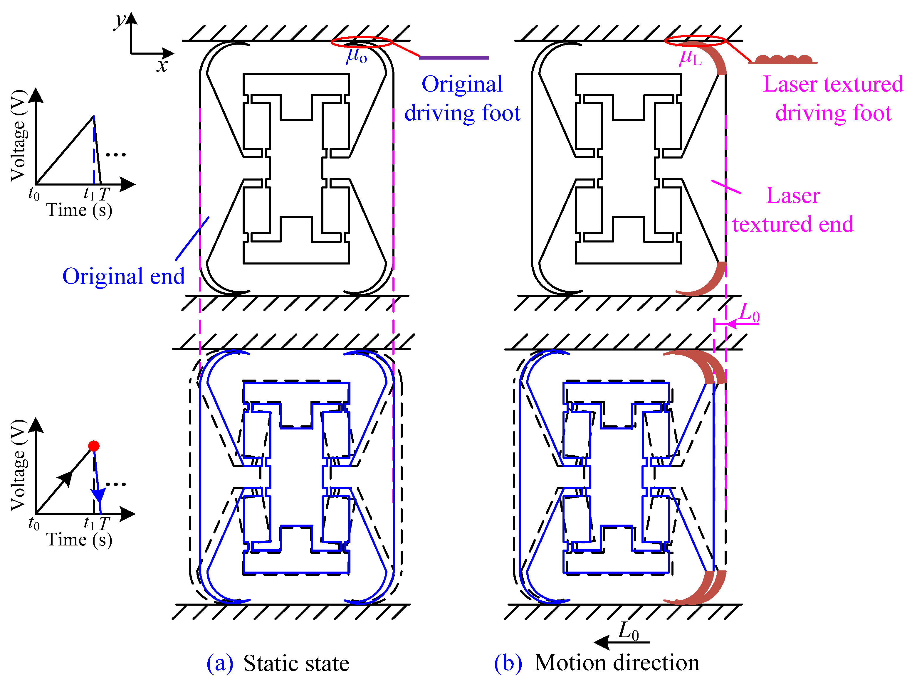
2. Structure of the Developed Actuator

Figure 2a shows the detailed structure of the developed asymmetric friction inertial impact piezoelectric actuator. It includes a symmetrically compliant mechanism (SCM) with laser-textured driving feet at one end, a piezoelectric stack (PES), two parallel guide rails and a base. The overall size of the actuator is 100 mm × 94 mm × 31 mm. These two parallel guide rails are installed on the base by screws. The SCM with Al 7075 has two pairs of arc-shaped driving feet, and it is nested in the two parallel guide rails, working as the mover. To generate the asymmetric frictions, microstructures are fabricated on the surface of the driving feet at one end by laser texturing. The driving feet with microstructures are referred to as the laser-textured end, and the other end without microstructures is referred to as the original end. Figure 1b shows the detailed structure of the arc-shaped driving foot. The main structural parameters are given in Table 1 based on our previous study [38]. To generate positive pressure, the inside width of two parallel guide rails is designed to be 0.3 mm smaller than that of the SCM. When the SCM is nested into the two parallel guide rails, the driving feet are deformed, and preloading forces will emerge between each driving foot and the guide rails. Furthermore, the friction coefficients of the laser-textured driving feet differ from those of the original driving feet, generating asymmetric frictions.
Figure 3 shows the motion process of the actuator according to its structure. As the SCM has a symmetric structure, the forces and deformations are completely consistent. Therefore, the actuator cannot achieve effective step motion if the surfaces of the driving feet at the two ends are the same, as shown in Figure 3a. However, with microstructures fabricated on the surfaces of the driving feet at one end, the friction coefficients (μo and μL) of the two ends would be different. When the SCM is deformed with the elongation of the PES, asymmetric frictions occur at the two ends. According to the asymmetric friction motion principle [38], the actuator with laser-textured driving feet can generate displacement (L0) along the negative-x axis in one motion period, as shown in Figure 3b.

3. Selection of Microstructures for Laser Texturing of the Driving Foot

According to some previous studies [39,40,41], the non-smooth surface of natural animal bodies, such as convex hulls, ridges and concaves, can effectively tune the surface friction properties. Therefore, four kinds of typical microstructures were selected as the basic microstructures and further experimentally compared and analyzed. Four arc-shaped driving feet were machined by wire electrical discharge machining (WEDM) with Al 7075, as shown in the insert in Figure 4a. Four kinds of microstructures, i.e., striped convex, square convex, circular convex and circular concave, were fabricated on the four arc-shaped driving feet by a fiber nanosecond pulsed laser with a wavelength of 1064 nm, pulse duration of 7 ns, repetition frequency of 600 kHz, scanning speed of 2 mm/s and average power of 15.8 W. An optical microscope (OM, DSX500, Olympus, Tokyo, Japan) was used to observe the four kinds of microstructures of the laser-textured driving feet surfaces; the results are shown in Figure 4.
An experimental system was established to test the friction properties of the four laser-textured driving feet, as shown in Figure 5a, including an IPC (industrial personal computer), a friction test unit, an analog output card (PCI NI6722, National Instruments Corporation, Austin, TX, USA), a voltmeter and a 24 V DC power supply. As the core part of the experimental system, the friction test unit is constituted by an X positioning stage, two lifting platforms, sensor I, signal amplifier I, sensor II, signal amplifier II, a rope, a polished disc with a mandrel, a driving foot, a base, a bearing and a transition plate. To reduce the effect of environmental vibration, all experiments were performed on a vibration-isolated optical table.
The measuring principle corresponding to the established experimental system is illustrated in Figure 5b. Sensor I and sensor II were used to measure the lateral force and positive pressure between the driving foot and polished disc, respectively. The standard weights were used to calibrate the voltage–force relationship of sensor I and sensor II. To measure the positive pressure between the driving foot and the polished disc, the driving foot was installed below the tangential position of the polished disc. The base with a polished disc and sensor II were fixed on two lifting platforms. The positive pressure was adjusted by two lifting platforms. The detected signal (positive pressure) of sensor II was amplified by signal amplifier II and recorded by the voltmeter. To test the lateral force, sensor I was fixed to the X positioning stage and controlled by software on the IPC. Sensor I was connected with the polished disc by a rope. Finally, when the positive pressure is constant, the X positioning stage with sensor I moves along the negative-x axis, driving the rope to pull the polished disc to rotate clockwise. During the test process, the detected signal (the lateral force) of sensor I was amplified by signal amplifier I and transmitted to the PCI analog output card, for further processing by the IPC. In addition, although the measured frictions include the friction between the bearing and the mandrel, all tests were completed using the same experimental system. Therefore, the measured lateral force can be approximately regarded as the maximum static friction.
Given the aforementioned experimental system and measuring principle, the maximum static friction (fo) of the original driving foot was tested first, with a result of 0.47 N under positive pressure of 1.92 N, as shown in Figure 6. Then, the maximum static frictions (fL) of the four laser-textured driving feet were tested under the same positive pressure, with results of 0.57 N, 0.6 N, 0.57 N and 0.48 N, respectively, as shown in Figure 7. Accordingly, the friction coefficient (μo) of the original driving foot is 0.24, and the friction coefficients (μL) of the four laser-textured driving feet are 0.30, 0.31, 0.30 and 0.25, respectively. Compared with the original driving foot, the friction coefficients of the four laser-textured driving feet are increased. According to the asymmetric friction principles [38], if the difference in friction coefficient between the original end and the laser-textured end is larger, the actuator would have better output characteristics. Therefore, two kinds of microstructures (striped convex and square convex) were selected for subsequent experiments, named Ta and Tb microstructures, respectively, for convenience. To test the output characteristics of the actuator with these two microstructures, Ta and Tb microstructures were fabricated on the surfaces of the driving feet at one end by laser texturing.

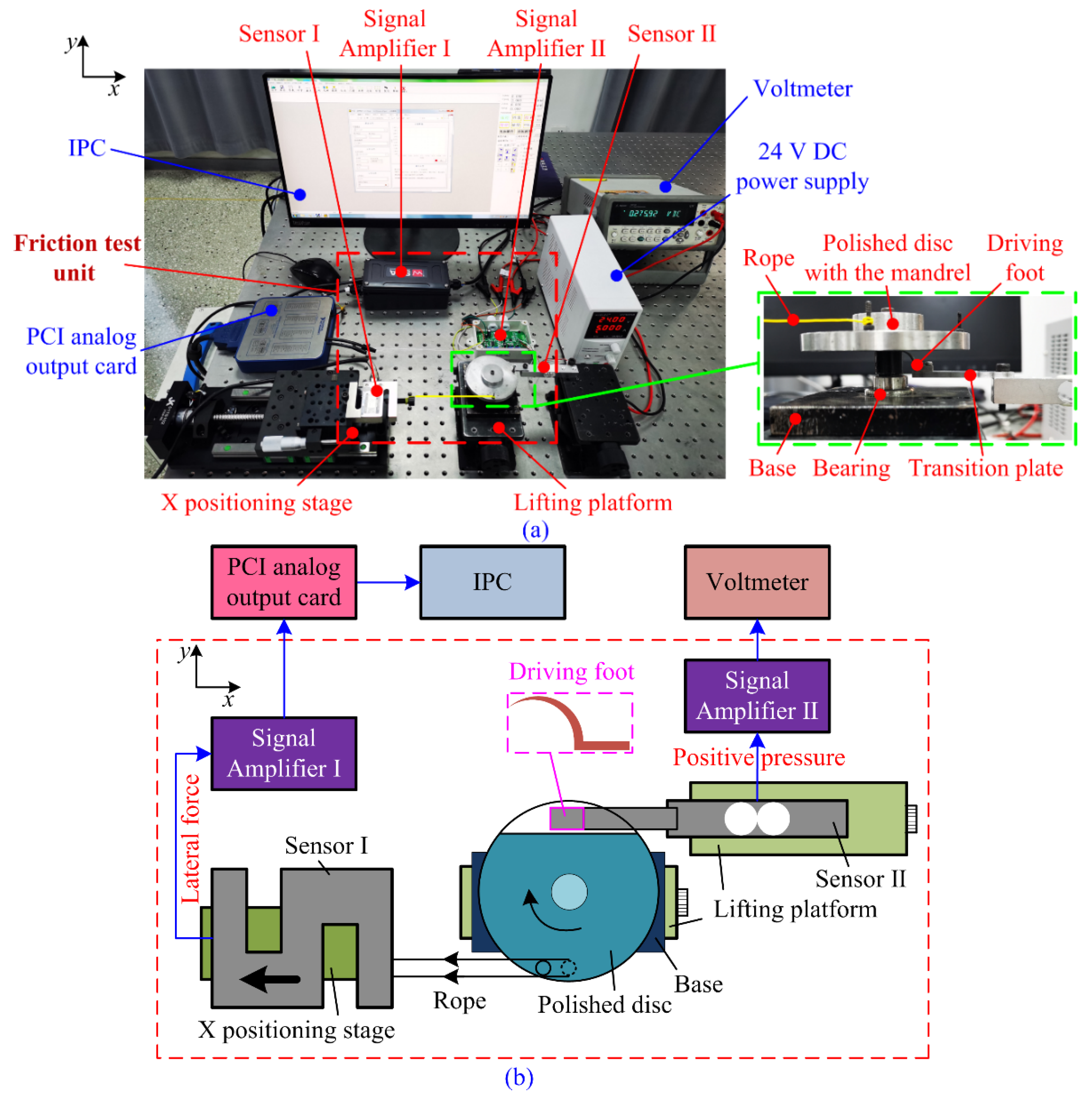
4. Experiments and Output Characteristics of the Actuator

To verify that the actuator could also achieve the stable motion by tuning the friction coefficients between the SCM and two parallel guide rails, a prototype was fabricated, and its output characteristics were tested using the experimental system, as shown in Figure 8. The signal generator (DG4062, RIGOL Technologies, Suzhou, China) produces a sawtooth-type driving voltage signal. Then, the signal is enlarged 15 times by the signal amplifier (E01.A3, Harbin Core Tomorrow Science & Technology Co., Ltd., Harbin, China) and applied to the PES (5 mm × 5 mm × 20 mm, AE0505D16DF, TOKIN, Japan; nominal displacement output: 17.4 ± 2.0 μm at 150 V) to drive the prototype. The motion displacement of the prototype was tested by a laser displacement sensor (ILD2300-2, Micro-Epsilon, Ortenburg, Germany), and the collected data were further processed by the IPC. The corresponding height between the prototype and laser displacement sensor was adjusted by the lifting platforms.

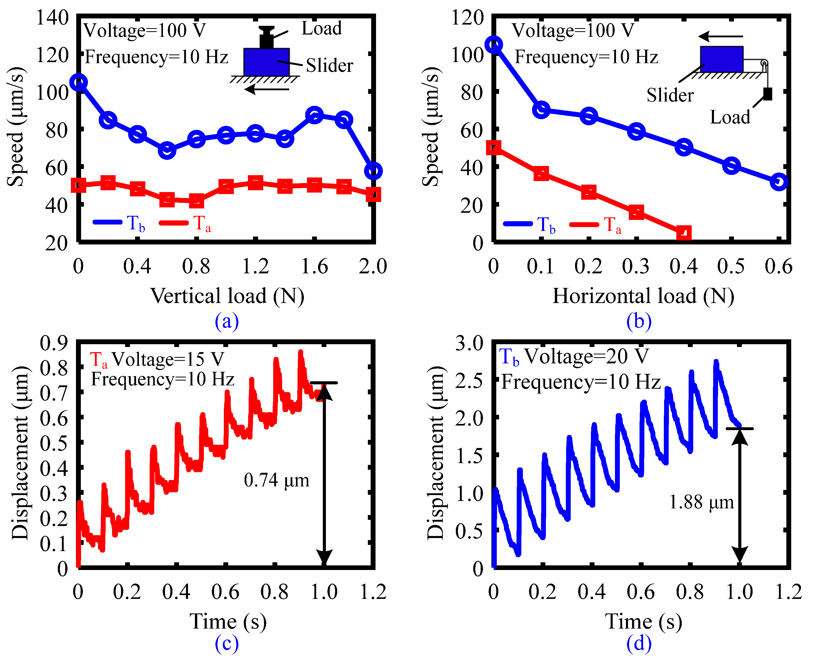
4.1. Output Characteristics with Various Working Gaps

The width of the two parallel guide rails, defined as the working gap, could significantly affect the output characteristics of the actuator. Taking the Tb microstructure as an example, Figure 9 shows the output displacement characteristics of the actuator with different working gaps when the driving voltage and frequency are 100 V and 10 Hz, respectively. A working gap of 58.6 mm was selected as the initial value based on our previous study [38]. However, with this working gap, the output displacement within 1 s is only 1.79 μm, possibly because the thickness of the driving foot is the same as that of the thick end in the previous study, resulting in high frictions between the SCM and the two parallel guide rails. The high frictions cause the output displacement to decrease. Therefore, it is necessary to increase the working gap. When the working gap is 58.7 mm, the actuator can achieve stable motion, as shown in the insert in Figure 9. When the working gap increases to 58.8 mm, the output displacement of the actuator can reach about 1 mm within 0.8 s. The reason for the large displacement is that the preload force between the SCM and guide rails is relatively small with a working gap of 58.8 mm, which can generate the small frictions. However, with this working gap, the output force of the actuator is relatively low. Therefore, to obtain better comprehensive output characteristics for the actuator, the subsequent experiments were performed with a working gap of 58.7 mm.

4.2. Output Characteristics with Various Driving Voltages and Frequencies

The output characteristics of the actuator with the Ta and Tb microstructures were further tested with various driving voltages (40 to 120 V) and driving frequencies (1 to 10 Hz) and a working gap of 58.7 mm. The results are presented in Figure 10. Figure 10a shows the accumulated displacement of the actuator within 1 s with a Ta microstructure, a fixed driving voltage of 100 V and various driving frequencies (1 to 10 Hz). Although the displacement increases with increased driving frequency, the evolution of the speed according to frequency fluctuates considerable, as shown in the insert in Figure 10a. The relatively small difference in friction coefficient between the Ta microstructure surface and the original surface results in an unstable motion. On the other hand, due to this small difference in the friction coefficient, the contact state between the SCM and guide rails is easily affected by fabrication and assembly errors, resulting in motion instability. Compared with the Ta microstructure, the difference in friction coefficient between the Tb microstructure surface and the original surface is relatively large. Therefore, the actuator with the Tb microstructure has better output characteristics, as shown in Figure 10c and the insert in Figure 10c. For example, when the driving frequency increases from 1 to 10 Hz, the speed–frequency curve obtained with the Tb microstructure shows a linear increasing tendency, indicating stable motion. In addition, under 100 V and 10 Hz, the output displacement obtained with the Tb microstructure reaches 104.8 μm within 1 s, compared to only 50.1 μm with the Ta microstructure. Therefore, a relatively high speed can be achieved by the Tb microstructure.
Figure 10b,d shows the displacement–time curves of the actuator obtained with Ta and Tb microstructures with a fixed driving frequency of 10 Hz and various driving voltages (40 to 120 V). For both Ta and Tb microstructures, the actuator can achieve stable motion under different driving voltages, but the actuator with the Tb microstructure has obvious advantages in terms of accumulated output displacement within 1 s. For example, under 120 V and 10 Hz, the accumulated output displacement is 117.5 μm for the Tb microstructure compared to only 60.6 μm for the Ta microstructure. Therefore, under various driving voltages and frequencies, relatively high motion stability and speed can be achieved for the actuator by employing the Tb microstructure.

4.3. Loading Capacity and Resolution

Loading capacity is an indispensable output characteristic for practical applications of actuators. Therefore, the vertical and horizontal loading capacities of the actuator with were tested with Ta and Tb microstructures under 100 V and 10 Hz. Figure 11a,b shows the experimental methods and results. To test the vertical loading capacity, a standard weight was placed directly on the SCM. When the vertical load is in the range of 0 to 2 N, the speed of the actuator with the Tb microstructure is still higher than that of the actuator with the Ta microstructure. For tests of horizontal loading capacity, a pulley was used to convert the standard weight to the horizontal force and applied to the SCM. The speeds of the actuator with the Ta and Tb microstructures reduce to 4.85 μm/s and 31.91 μm/s when the horizontal load is 0.4 N and 0.6 N, respectively. In comparison, the actuator with the Tb microstructure has a better loading capacity than that with the Ta microstructure.
For piezoelectric actuators, the minimum stable stepping displacement, i.e., the resolution, is another important parameter. To measure the resolution, the driving frequency was kept at 10 Hz, and the driving voltage was gradually increased from zero without an external load. The minimum stable stepping motions of the actuator with the Ta and Tb microstructures are achieved when the voltages are increased to 15 V and 20 V, respectively. Figure 11c,d shows the output displacements of the actuator in ten steps obtained with the Ta and Tb microstructures. The accumulated displacements are 0.74 μm and 1.88 μm, so the resolution of the actuator with the Ta and Tb microstructures can be derived as 74 nm and 188 nm, respectively. Although the actuator with the Tb microstructure exhibits stable motion and relatively high loading capacity, its resolution is lower than that of the actuator with the Ta microstructure. Therefore, for some practical applications that require a higher resolution, the Ta microstructure should be selected

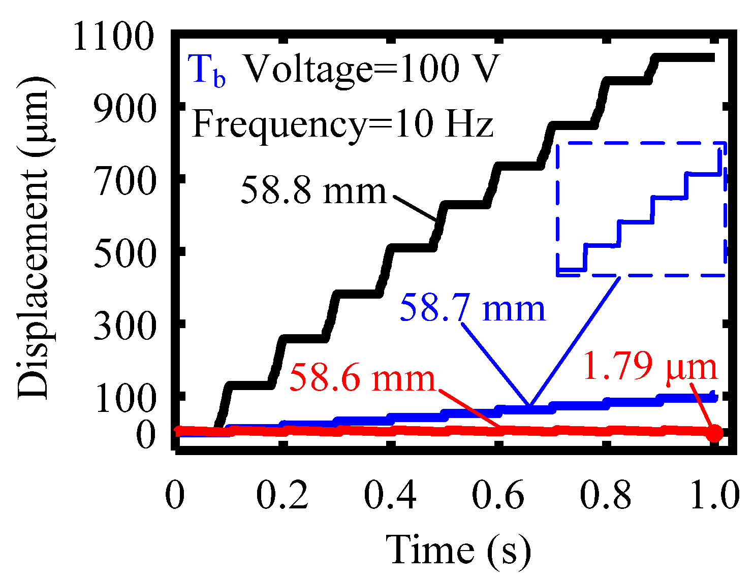
4.4. Output Characteristics of the Actuator with the Tb Microstructure

According to the above comparison, the actuator with the Tb microstructure exhibits relatively high motion stability, speed and loading capacity, so its output characteristics were further tested. Figure 12a presents the speed change according to driving frequency (1 to 450 Hz) under a fixed driving voltage of 100 V. The actuator with the Tb microstructure reaches a maximum speed of 2.523 mm/s under 100 V and 300 Hz.
Both forward and reverse motions of the actuator are required in practical applications. By simply changing the driving voltage waveform to that shown in the insert in Figure 12b, the actuator can realize the reverse motion along the positive x axis. The reverse motion speed is faster than the forward motion speed, as explained in our previous study [38].

4.5. Comparison and Discussion

Table 2 shows a comparison of output characteristics between previously reported inertial impact piezoelectric actuators and the actuator with the Tb microstructure developed in the present study, including the frequency bandwidth, maximum speed, resolution, and horizontal and vertical loading capacities. The actuator presented in this study has a high-frequency bandwidth and motion speed. The main aim of [37] was to improve the frequency bandwidth of the inertial impact actuator so that the actuator could move stably in a large frequency range. It is well known that inertial impact piezoelectric actuators generally have a low-frequency bandwidth due to their intrinsic structure (the main mass and inertial mass), as listed in Table 2 (Refs. [29,33,42,43]). Compared to these actuators, the actuator designed according to the newly proposed asymmetric friction principle presents with an improved frequency bandwidth and motion speed.
Although the actuator designed in our previous study in [38] achieved improved output characteristics by employing an asymmetric structure, this resulted in an increase in the structural parameters, causing difficulty with respect to structural design and optimization. Alternatively, the actuator in this study employs a symmetric structure and achieves asymmetric friction driving by tuning the friction coefficient. Although some output characteristics are weakened compared to those reported in [38], the structure is simplified, and the output characteristics are still quite competitive compared to traditional inertial impact actuators.

5. Conclusions

In this study, we developed an asymmetric friction inertial impact actuator using a symmetrically compliant mechanism (SCM), and asymmetric frictions were achieved by laser texturing of the driving feet at one end of the SCM. Four kinds of microstructures were initially fabricated on the driving feet, and their friction properties were experimentally tested. Accordingly, two kinds of microstructures (striped convex and square convex, i.e., Ta and Tb microstructures) with relatively large friction coefficients were selected for subsequent experiments. Output characteristics of the actuator with these two microstructures were measured and comparatively analyzed. The experimental results showed that the actuator with the Tb microstructure had better output characteristics in terms of motion stability, speed and loading capacity. It achieved a maximum speed of 2.523 mm/s, a resolution of 188 nm, a vertical loading capacity of 2 N and a horizontal loading capacity of 0.6 N, whereas the actuator with the Ta microstructure had a higher positioning resolution of 74 nm. According to comparison with previously reported inertial impact piezoelectric actuators, the output characteristics of the actuator developed herein are quite competitive.
By tuning the friction coefficient, a symmetric structure can be used to simplify the structural design of asymmetric friction inertial impact actuators. The topography of the microstructure affects the output characteristics of the actuator. Therefore, various output characteristics can be obtained by selecting different microstructures.

Author Contributions

Conceptualization, H.H.; methodology, W.S.; validation, W.S., Y.L. and X.L.; investigation, Z.X. and Z.Y.; resources, H.H.; writing—original draft preparation, W.S. and Y.L.; writing—review and editing, H.H.; supervision, H.H.; project administration, H.H.; funding acquisition, H.H. All authors have read and agreed to the published version of the manuscript.

Funding

This work was supported by the National Natural Science Foundation of China (Grant No. 52075221), the Graduate Innovation Fund of Jilin University (Grant No. 101832020CX100) and the Fundamental Research Funds for the Central Universities (2019–2022).

Institutional Review Board Statement

Not applicable.

Informed Consent Statement

Not applicable.

Data Availability Statement

The data that support the findings of this study are available from the corresponding authors upon reasonable request.

Conflicts of Interest

The authors declare no conflict of interest.

References

  1. Elahi, H.; Eugeni, M.; Gaudenzi, P.; Qayyum, F.; Swati, R.F.; Khan, H.M. Response of piezoelectric materials on thermomechanical shockingand electrical shocking for aerospace applications. Microsyst. Technol. 2018, 24, 3791–3798. [Google Scholar] [CrossRef]
  2. Li, M.; Yuan, J.; Guan, D.; Chen, W. Application of piezoelectric fiber composite actuator to aircraft wing for aerodynamic performance improvement. Sci. China Technol. Sci. 2011, 54, 395–402. [Google Scholar] [CrossRef]
  3. Qing, X.; Li, W.; Wang, Y.; Sun, H. Piezoelectric Transducer-Based Structural Health Monitoring for Aircraft Applications. Sensors 2019, 19, 545. [Google Scholar] [CrossRef] [PubMed]
  4. Holmström, S.T.S.; Baran, U.; Urey, H. Laser Scanners A Review. J. Microelectromechanical Syst. 2014, 23, 259–274. [Google Scholar] [CrossRef]
  5. Koh, K.H.; Kobayashi, T.; Hsiao, F.L.; Lee, C. Characterization of piezoelectric PZT beam actuators for driving 2D scanningmicromirrors. Sens. Actuators A Phys. 2010, 162, 336–347. [Google Scholar] [CrossRef]
  6. Wang, Z. Piezopotential gated nanowire devices Piezotronics and piezo-phototronics. Nano Today 2010, 5, 540–552. [Google Scholar] [CrossRef]
  7. Chorsi, M.T.; Curry, E.J.; Chorsi, H.T.; Das, R.; Baroody, J.; Purohit, P.K.; Ilies, H.; Nguyen, T.D. Piezoelectric Biomaterials for Sensors and Actuators. Adv. Mater. 2019, 31, 1802084. [Google Scholar] [CrossRef] [PubMed] [Green Version]
  8. Yuan, H.; Lei, T.; Qin, Y.; He, J.H.; Yang, R. Design and application of piezoelectric biomaterials. J. Phys. D Appl. Phys. 2019, 52, 194002. [Google Scholar] [CrossRef] [Green Version]
  9. Zheng, Q.; Shi, B.; Li, Z.; Wang, Z. Recent Progress on Piezoelectric and Triboelectric Energy Harvesters in Biomedical Systems. Adv. Mater. 2017, 4, 1700029. [Google Scholar] [CrossRef]
  10. Ji, F.; Li, T.; Yu, S.; Wu, Z.; Zhang, L. Propulsion Gait Analysis and Fluidic Trapping of Swinging Flexible Nanomotors. ACS Nano 2021, 15, 5118–5128. [Google Scholar] [CrossRef]
  11. Li, T.; Zhang, A.; Shao, G.; Wei, M.; Guo, B.; Zhang, G.; Li, L.; Wang, W. Janus Microdimer Surface Walkers Propelled by Oscillating Magnetic Fields. Adv. Funct. Mater. 2018, 28, 1706066. [Google Scholar] [CrossRef]
  12. Wang, H.; Yu, S.; Liao, J.; Qing, X.; Sun, D.; Ji, F.; Song, W.; Wang, L.; Li, T. A Robot Platform for Highly Efficient Pollutant Purification. Front. Bioeng. Biotechnol. 2022, 10, 903219. [Google Scholar] [CrossRef] [PubMed]
  13. Guan, C.; Jiao, Z. A piezoelectric direct-drive servo valve with a novel multi-body contacting spool-driving mechanism: Design, modelling and experiment. P. I. Mech. Eng. C-J. Mec. 2014, 228, 169–185. [Google Scholar] [CrossRef]
  14. Mohith, S.; Upadhya, A.R.; Navin, K.P.; Kulkarni, S.M.; Rao, M. Recent trends in piezoelectric actuators for precision motion and their applications: A review. Smart Mater. Struct. 2021, 30, 013002. [Google Scholar] [CrossRef]
  15. Wang, L.; Chen, W.; Liu, J.; Deng, J.; Liu, Y. A review of recent studies on non-resonant piezoelectric actuators. Mech. Syst. Signal Process. 2019, 133, 106254. [Google Scholar] [CrossRef]
  16. Gao, Y.; Wen, J.; Ma, J.; Zhang, Y.; Wang, R.; Hu, Y.; Li, J. A self-adapting linear inchworm piezoelectric actuator based on a permanent magnets clamping structure. Mech. Syst. Signal Process. 2019, 132, 429–440. [Google Scholar] [CrossRef]
  17. Li, J.; Zhao, H.; Shao, M.; Zhou, X.; Huang, H.; Fan, Z. Design and experiment performances of an inchworm type rotary actuator. Rev. Sci. Instrum. 2014, 85, 085004. [Google Scholar] [CrossRef]
  18. Shao, S.; Song, S.; Shao, Y.; Xu, M. Long-range piezoelectric actuator with large load capacity using inchworm and stick-slip driving principles. Precis. Eng. 2022, 75, 167–179. [Google Scholar] [CrossRef]
  19. Deng, J.; Liu, Y.; Chen, W.; Yu, H. A XY Transporting and Nanopositioning Piezoelectric Robot Operated by Leg Rowing Mechanism. IEEE-ASME Trans. Mechatron. 2019, 24, 207–217. [Google Scholar] [CrossRef]
  20. Liu, R.; Wen, Z.; Cao, T.; Lu, C.; Wang, B.; Wu, D.; Li, X. A precision positioning rotary stage driven by multilayer piezoelectric stacks. Precis. Eng. 2022, 76, 226–236. [Google Scholar] [CrossRef]
  21. Liu, Y.; Wang, L.; Gu, Z.; Quan, Q.; Deng, J. Development of a Two-Dimensional Linear Piezoelectric Stepping Platform Using Longitudinal-Bending Hybrid Actuators. IEEE Trans. Ind. Electron. 2019, 66, 3030–3040. [Google Scholar] [CrossRef]
  22. Delibas, B.; Koc, B. L1B2 Piezo Motor Using D33 Effect. In Proceedings of the ACTUATOR 2018: 16th International Conference on New Actuators, Bremen, Germany, 25–27 June 2018; pp. 1–4. [Google Scholar]
  23. Feng, Y.; Chang, X.; Liu, H.; Hu, Y.; Li, T.; Li, L. Multi-response biocompatible Janus micromotor for ultrasonic imaging contrast enhancement. Appl. Mater. Today 2021, 23, 101026. [Google Scholar] [CrossRef]
  24. Tian, X.; Liu, Y.; Deng, J.; Wang, L.; Chen, W. A review on piezoelectric ultrasonic motors for the past decade: Classification, operating principle, performance, and future work perspectives. Sens. Actuators A Phys. 2020, 306, 111971. [Google Scholar] [CrossRef]
  25. Tang, J.; Wei, J.; Wang, Y.; Xu, Z.; Huang, H. A Novel Rotation-Structure Based Stick-Slip Piezoelectric Actuator with High Consistency in Forward and Reverse Motions. Actuators 2021, 10, 189. [Google Scholar] [CrossRef]
  26. Yang, X.; Tang, J.; Guo, W.; Huang, H.; Fan, H.; Liu, J.; Li, T. Design and Analysis of a Stepping Piezoelectric Actuator Free of Backward Motion. Actuators 2021, 10, 200. [Google Scholar] [CrossRef]
  27. Nguyen, X.H.; Mau, T.H.; Meyer, I.; Dang, B.L.; Pham, H.P. Improvements of Piezo-Actuated Stick–Slip Micro-Drives: Modeling and Driving Waveform. Coatings 2018, 8, 62. [Google Scholar] [CrossRef] [Green Version]
  28. Shao, Y.; Shao, S.; Xu, M.; Song, S.; Tian, Z. An inertial piezoelectric actuator with miniaturized structure and improved load capacity. Smart Mater. Struct. 2019, 28, 055023. [Google Scholar] [CrossRef]
  29. Zhang, E.; Hu, Y.; Bao, H.; Li, J.; Ma, J.; Wen, J. A linear inertial piezoelectric actuator using a single bimorph vibrator. Smart Mater. Struct. 2019, 28, 115020. [Google Scholar] [CrossRef]
  30. Hunstig, M. Piezoelectric Inertia Motors—A Critical Review of History, Concepts, Design, Applications, and Perspectives. Actuators 2017, 6, 7. [Google Scholar] [CrossRef] [Green Version]
  31. Higuchi, T.; Watanabe, M.; Kudou, K. Precise positioner utilizing rapid deformations of a piezoelectric element. J. Jpn. Soc. Precis. Eng. 1988, 54, 2107–2112. [Google Scholar] [CrossRef] [Green Version]
  32. Okamoto, Y.; Yoshida, R.; Sueyoshi, H. The development of a smooth impact drive mechanism (SIDM) using a piezoelectric element. Konica Minolta Technol. Rep. 2004, 1, 23–26. [Google Scholar]
  33. Hu, Y.; Wang, R.; Wen, J. A Low-Frequency Structure-Control-Type Inertial Actuator Using Miniaturized Bimorph Piezoelectric Vibrators. IEEE Trans. Ind. Electron. 2019, 66, 6179–6188. [Google Scholar] [CrossRef]
  34. Zhang, Z.M.; An, Q.; Li, J.W.; Zhang, W.J. Piezoelectric friction–inertia actuator-a critical review and future perspective. Int. J. Adv. Manuf. Technol. 2012, 62, 669–685. [Google Scholar] [CrossRef]
  35. Cao, Y.; Xu, Z.; You, L.; Wu, Y.; Huang, H. An inertial piezoelectric actuator with small structure but large loading capacity. Rev. Sci. Instrum. 2021, 92, 085004. [Google Scholar] [CrossRef] [PubMed]
  36. Hu, Y.; Lin, S.; Ma, J.; Zhang, Y.; Li, J.; Wen, J. Piezoelectric inertial rotary actuator operating in two-step motion mode for eliminating backward motion. Appl. Phys. Lett. 2020, 117, 031902. [Google Scholar] [CrossRef]
  37. Xu, Z.; Yang, Z.; Wang, K.; Li, X.; Dong, J.; Huang, H. A bionic inertial piezoelectric actuator with improved frequency bandwidth. Mech. Syst. Signal Process. 2021, 156, 107620. [Google Scholar] [CrossRef]
  38. Sun, W.; Xu, Z.; Wang, K.; Li, X.; Tang, J.; Yang, Z.; Huang, H. An impact inertial piezoelectric actuator designed by means of the asymmetric friction. IEEE Trans. Ind. Electron. 2022, 1. [Google Scholar] [CrossRef]
  39. Bushnell, D.M. Drag Reduction in Nature. Annu. Rev. Fluid Mech. 1991, 23, 65–79. [Google Scholar] [CrossRef]
  40. Ren, L. Progress in the bionic study on anti-adhesion and resistance reduction of terrain machines. Sci. China Ser. E Technol. Sci. 2009, 52, 273–284. [Google Scholar] [CrossRef]
  41. Ren, L.; Liang, Y. Biological couplings: Classification and characteristic rules. Sci. China Ser. E Technol. Sci. 2009, 52, 2791–2800. [Google Scholar] [CrossRef]
  42. Shen, D.; Wen, J.; Ma, J.; Hu, Y.; Wang, R.; Li, J. A novel linear inertial piezoelectric actuator based on asymmetric clamping materials. Sens. Actuators A Phys. 2020, 303, 111746. [Google Scholar] [CrossRef]
  43. Wang, R.; Hu, Y.; Shen, D.; Ma, J.; Wen, J. Design and Experimental Performance of a Novel Piezoelectric Inertial Actuator for Magnetorheological Fluid Control Using Permanent Magnet. IEEE Access 2019, 7, 43573–43580. [Google Scholar] [CrossRef]
Figure 1. The working principles of (a) the traditional inertial impact actuator and (b) the asymmetric friction inertial impact actuator.
Actuators 11 00211 g001
Figure 2. (a) Structure of the developed actuator with laser-textured driving feet and (b) detailed structure of a quarter of the arc-shaped driving foot.
Actuators 11 00211 g002
Figure 3. The motion process of the actuator with (a) the original driving feet and (b) the laser-textured driving feet.
Actuators 11 00211 g003
Figure 4. Four kinds of microstructures fabricated on the driving feet surfaces by laser texturing: (a) striped convex, (b) square convex, (c) circular convex and (d) circular concave.
Actuators 11 00211 g004
Figure 5. (a) The established experimental system for testing the friction properties of the four laser-textured driving feet and (b) a schematic diagram illustrating the measuring principle.
Actuators 11 00211 g005
Figure 6. Lateral force–time curves of the original driving foot.
Actuators 11 00211 g006
Figure 7. Lateral force–time curves of the four laser-textured driving feet: (a) striped convex, (b) square convex, (c) circular convex and (d) circular concave.
Actuators 11 00211 g007
Figure 8. The established experimental system.
Actuators 11 00211 g008
Figure 9. Output displacement of the actuator obtained with various working gaps. The driving voltage and frequency are 100 V and 10 Hz, respectively.
Actuators 11 00211 g009
Figure 10. Output displacement change over time obtained under various driving voltages (40 to 120 V) and driving frequencies (1 to 10 Hz): (a,b) output characteristics of the actuator with the Ta microstructure, (c,d) output characteristics of the actuator with the Tb microstructure.
Actuators 11 00211 g010
Figure 11. Motion speed change with (a) a vertical load and (b) a horizontal load. (c,d) Resolution testing results of the actuator with the Ta and Tb microstructures without an external load.
Actuators 11 00211 g011
Figure 12. (a) Speed change according to driving frequency (1 to 450 Hz) under a fixed driving voltage of 100 V. (b) Reverse stepping characteristics of the actuator in the frequency range of 1 to 10 Hz.
Actuators 11 00211 g012
Table 1. The main structural parameters of a quarter of the arc-shaped driving foot.
ParameterMeaningValue
r1Radius of circle O17.5 mm
r2Radius of circle O27 mm
tThickness of the driving foot1.6 mm
x1Distance between points O1 and O14.5 mm
x2Distance between points O2 and O13.4 mm
Table 2. Comparison of output characteristics between actuators reported in previous studies and the present study.
Reference[29][33][42][43][37][38]This Work
(Tb)
Frequency bandwidth (Hz)45351311275390300
Maximum speed (mm/s)/0.440.20.031.2187.3112.523
Resolution (nm)60030200020214221188/Ta-74
Horizontal load (N)////0.61.40.6
Vertical load (N)4.250.060.9817202
Publisher’s Note: MDPI stays neutral with regard to jurisdictional claims in published maps and institutional affiliations.

