Article

3D Printing of Silicone Elastomers for Soft Actuators

School of Electrical and Mechanical Engineering, Jiangsu Provincial Key Laboratory of Advanced Robotics, Soochow University, Suzhou 215021, China
*
Author to whom correspondence should be addressed.
These authors contributed equally to this work.
Actuators 2022, 11(7), 200; https://doi.org/10.3390/act11070200
Submission received: 14 June 2022 / Revised: 8 July 2022 / Accepted: 12 July 2022 / Published: 18 July 2022
(This article belongs to the Special Issue 3D Printable Soft Robotics and Soft Actuators)

Abstract

:
A procedure for 3D printing of silicone elastomers with a direct ink writing (DIW) process has demonstrated great potential in areas as diverse as flexible electronics, medical devices, and soft robotics. In this report, we propose a comprehensive guide for printing highly stretchable silicones in response to material, equipment and process dilemmas. Specifically, we first tested the material properties of Dow Corning 737, then modeled and simulated two commonly used needles to select a suitable needle, followed by parameter optimization experiments using the built DIW printer to find out the appropriate printing speed and layer height with a defined air pressure and needle diameter. Finally, the optimal combination of parameters was obtained. For further demonstration, artificial muscles and structurally complex soft grippers were also printed directly to verify the feasibility of high-precision 3D printing of soft actuators with soft materials. We believe that this work could provide a guide for further work using the DIW process to print soft matter in a wide range of application scenarios.

1. Introduction

Robots are usually composed of rigid components such as hinges and bolts. A generated force can be transmitted to the designated position to realize various movements and functions through the transmission mechanism and other system components [1,2]. These robots are usually made of hard metal materials and require large processing platforms for complex machining and assembly processes, which limit their elastic deformation ability and make their shapes difficult to adapt to external constraints and obstacles. These rigid parts also make them lack the necessary security in the process of human-computer interaction. By contrast, soft robots made mainly of soft, highly elastic silicone rubber and flexible materials such as polyurethane and hydrogel can show great deformations and adapt to a variety of complex environments, such as being able to steer in tight spaces without damaging internal stresses and stress concentrations [3,4]. Because of their good flexibility, safety and ability to complete complex movements, soft robots are the ideal choice for human–computer interaction.
Soft robots are inspired by natural mechanisms, such as invertebrates such as cephalopods [5,6,7] and insect larvae [8], as well as vertebrates including snakes [9] and fish [10]. The body of the robot is made of flexible elastomer material with large deformation and can be driven by fluid (gas or liquid) [6] or smart materials such as shape memory alloy [11] and dielectric elastomer [12]. The soft robot can sense the environment and its own state by combining the flexible and high sensing density detection devices with different principles, such as electrical [13], optical [14] and air pressure [15]. The soft robot can operate in a limited space and change its shape according to the surrounding environment. Theoretically, it has infinite degrees of freedom, so its end-effector has the ability to reach any point in the workspace [2]. Silicone elastomers have been widely used in flexible electronics, soft robots and other fields due to their excellent flexibility, adaptability and biocompatibility. However, the slow cure speed of these silicone materials constrains the fabrication of objects to only traditional methods, such as casting, spin coating, and so forth, which add cost and limit their applications [16]. Currently, many researchers have attempted to apply silicone elastomers to 3D printing processes. Among them, the direct ink writing (DIW) process is a promising solution, which extrudes silicone ink from a nozzle to form a printed silicone fiber. Due to its outstanding advantages in multi-material printing, it has promoted the advancement of soft materials 3D printing technology and the development of flexible functional devices. Due to the characteristics of high speed, high efficiency and high precision, 3D printing has become the key technology to promote the development of soft robot technology and can realize the production of soft robots with higher precision, more complex structure and more prominent functions. Because of the diversity of printing methods and materials, 3D printing technology has become a versatile and powerful technological platform for future advanced manufacturing [17,18].
As an important part of soft robots, a soft actuator can realize different movements and functions, such as grasping objects, bending and crawling. Many scholars and research institutions have carried out in-depth research on DIW-printed soft robots and soft actuators and have obtained extensive research results. Jennifer A. Lewis et al. reported a method for fabricating soft actuators with complex sensor networks through embedded multi-material 3D printing (Figure 1a) [19]. The soft sense actuator (SSA) realizes proprioceptive and haptic feedback through embedded curvature, expansion and contact sensors. SSA is made by writing sensing and fluid networks directly into the molded elastomer matrix through embedded multi-material 3D printing (EMB3D). They assembled three SSAs together to create a soft robotic claw and demonstrated that soft robotic actuators have tactile, proprioceptive and thermal sensing by pinching different types of spheres. Yin Cheng et al. used polyacrylamide hydrogels to directly construct free-moving tentacle-like robots (Figure 1b) [20]. The geometry of the artificial tentacle is made by DIW-assisted printing. The artificial tentacle is characterized by four channels consisting of four laterally embedded chambers and the curvature can be controlled by the amount of water injected. The curvature of the artificial tentacle increases with the amount of water. The time-varying output of the four injection pump channels can be programmed to drive the artificial tentacle to rotate. Zeang Zhao et al. proposed a method for creating self-folding structures. They used a DIW printer to print silver nanoparticle inks on flat liquid phototropic polymer plates to form a circuit. The liquid photopolymer was cured by a light field with a variation of light intensity in 3D. This approach enabled complicated origami-based shape change devices and 3D electronics (Figure 1c) [21]. Michael W. Ehner et al. proposed soft robots made entirely of soft materials (Figure 1d) [22]. The body and microfluidic logic of the robot are fabricated using molding and soft lithography, respectively, and the pneumatic actuator networks, on-board fuel reservoirs and catalytic reaction chambers needed for movement are patterned within the body via a multi-material, embedded 3D printing technique. The integrated design and rapid fabrication approach enables the programmable assembly of multiple materials within this architecture, laying the foundation for all soft autonomous robots.
This paper presents a multi-material 3D printing method for soft actuators. In order to achieve the best effect of soft material 3D printing, parameter optimization of the 3D printing process and research of improving printing accuracy were mainly carried out, and two kinds of soft actuators were designed and manufactured. Firstly, the performance of soft materials used was tested and a DIW 3D printer which can realize multi-material printing is built. Then, the two types of needles were modeled and simulated, parameter optimisation experiments have been carried out. Finally, two soft actuators, artificial muscle and soft gripper, were printed to verify the experiment. The method of 3D printing soft actuators with soft materials proposed in this paper opens up a new and effective way for manufacturing soft robots with better performance and more flexible functions.

2. Methods and Materials

2.1. Direct Ink Writing Platform

This paper improves and builds a DIW printer for soft material printing based on a gantry-type 3D printing platform (Figure 2a). DIW works by first loading the polymer material into the print syringe and then using a servo unit such as an air pump or electric cylinder to drive a piston to force the polymer to flow out of the needle, which moves with the print nozzle to form a pre-defined 3D entity. It is mainly composed of four modules: soft material extrusion module, hardware module, software module and printing platform (Figure 2b–d).

2.2. Materials

The thixotropy of the polymer is the key property during the DIW process. Extruded polymers require a certain viscosity to be self-supporting, but high viscosity can cause difficulties in extrusion. The shear thinning property of silicone elastomers is perfectly suitable for DIW. At low flow rates or at rest, the molecular chains within the silicone elastomer are entangled with each other and therefore have a high viscosity, but as the flow rate increases, the molecular chains align in the direction of the shear force due to the shear force, which causes the viscosity of the material to decrease. This property of silicone elastomers ensures smooth extrusion and self-supporting molding (Figure 3a,b). In this paper, Dow Corning DC737 silicone was used as the printing material, and the rheological behavior of the fluid was tested by a research-grade rotational rheometer (Kinexus pro+).

2.3. Modeling and Simulation

The retractable nozzle is the driving unit of DIW, which can effectively extricate the polymer. Conical nozzles and straight tube nozzles are now commonly used in DIW. The difference in nozzle structure leads to different internal flow rates and pressures of polymer extrusion. In this paper, the meshing of the two nozzle models is shown in Figure 4, with the nozzle ports and center-line meshed to increase operational reliability. In the simulation, all silicone elastomers were set as an inelastic non-Newtonian fluid, the model used was Carreau, the viscosity at zero shear rate was µ0 = 41,761 Pa·s, the infinite shear rate viscosity was set to µinf = 0 Pa·s, the parameter with units of time was λ = 0.0173, the dimensionless parameter n = 0.538, the inlet pressure Pi was set to 1.38 × 10⁵ Pa (20 psi) and the outlet pressure P0 was set to 1.013 × 10⁵ Pa (a standard atmospheric pressure). According to Figure 4, it can be seen that the flow rate of the straight pipe nozzle changes more due to the special flow channel with varying cross-section. Under the same air pressure, the flow rate of the straight pipe nozzle is significantly smaller than that of the conical nozzle, and it is easier to plug the needle due to the high viscosity of the silicone elastomer. The diameter of the cone nozzle is smaller, and the flow rate in the nozzle increases exponentially at first and reaches an extreme value at the nozzle, so that the material is extruded smoothly and it does not plug the needle. Only a small pressure is required to ensure smooth extrusion and realize high-precision molding.

3. Parameter Optimization

3.1. Mono Fiber Printing Experiment

The typical parameters for DIW 3D printing are shown in Figure 5a. To form a continuous filament, the silicone ink is extruded out of the nozzle with a diameter D at a speed V0 by applying an air pressure P. Due to the viscoelasticity of the ink, the extrusion of silicone ink will lead to the die-swelling of the extruded fiber, which makes the extruded fiber diameter μD different from the nozzle diameter D. According to volume conservation, the diameter of the printed fiber can be expressed as
C = μ D V / V 0
The nozzle diameter D is fixed; V0 and P are positively correlated; and the die-swelling ratio μ is related to various factors such as polymer material properties, air pressure, needle diameter, etc. [23,24,25]. Although μ cannot be controlled quantitatively, its rate of change is so small that it can be neglected. Therefore, the print speed V is the main control parameter. This theoretical model is not limited to specific silicone materials and can be applied to a wide range of silicone materials.
The monofiber printing experiment is used to verify how to control the basic printing parameters to ensure the stability and continuity of the printed silicone fiber. In this paper, a needle with D = 0.41 mm and a print height of H = 1 mm was used as the basis for printing experiments. Multiple combinations of air pressure P and print speed V can usually be found for a selected needle diameter. Considering the printing accuracy and printing efficiency, this paper sought the best printing speed V under the case of air pressure P = 40 psi. The length of the printed monofiber was 100 mm, the printing speed was set to 12–30 mm/s and the speed interval for measurement was 2 mm/s. As the printing speed increased, the monofiber formed three different shapes: curved fiber, straight fiber and discontinuous fiber (Figure 5c).
As shown in Figure 5c, straight fibers printed at speeds between 18 and 24 mm/s are viewed as the ideal ones used in the DIW process. Therefore, five sets of experiments with velocity intervals of 1 mm/s were performed in this interval (19–23 mm/s). Ten fibers of equal length were printed in each set; their line widths c were measured by electron microscopy (Figure 5b), and frequency histograms of line widths were plotted. As shown in Figure 5d, the fiber width range was found to be between 402.1 and 420.2 μm at a print speed V of 20 mm/s. The mathematically expected mean fiber width C0 411.6 μm at this print speed is closest to 410 μm, so the optimal print speed V was determined to be 20 mm/s.

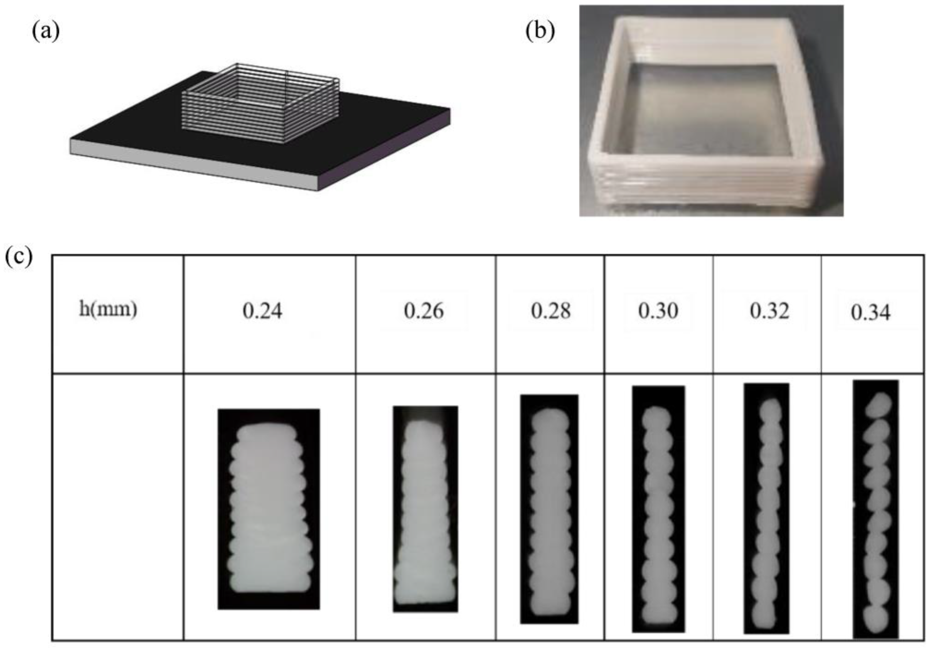
3.2. Fiber Wall Printing Experiment

The monofiber printing experiment ensures the accuracy of printing only from the perspective of lines and surfaces, while printing solids is a stacking process from lines to surfaces to bodies. Therefore, it is necessary to perform layer-by-layer superposition in the Z-direction to form a three-dimensional solid wall on the basis of the monofiber experiment.
The molding quality of 3D solids is mainly determined by the layer height h. Based on the best combination of monofilament process parameters (D = 0.41 mm, p = 40 psi, V = 20 mm/s), the layer heights h = 0.26 mm, 0.28 mm, 0.30 mm, 0.32 mm, 0.34 mm and 0.36 mm were taken for printing experiments, respectively, and the results were observed under the microscope (Figure 6c).
With the increase in the layer h, the distance between layers gradually increases, and the overlapping part between the upper and lower layers will also shrink. The gap between layers will not be filled by the silicone ink that is extruded and deformed by the pressure of the nozzle, and the gap gradually starts to appear. As the layer height h decreases, the overlap between the layers increases, and the overlap will be extruded and deformed to fill the gaps between the monofiber. This may cause excessive extrusion and make the single fibers extruded from the nozzle expand to both sides, affecting the stacking of the monofiber in the peripheral positions, thus affecting the molding quality of soft material 3D printing.
For the sample with layer height h = 0.30 mm, it can be observed that the whole cross-section is basically void-free, and the lines fit tightly with each other; hence, it is considered that h = 0.30 mm is the optimal layer height.
Based on the optimal parameter conditions (D = 0.41 mm, p = 40 psi, V = 20 mm/s, h = 0.30 mm), we printed some graphs. Figure 7a shows the printed graphics of the Dow Corning 737 material in black and white, and Figure 7b further demonstrates that more complex 3D structures can be printed.

4. Result and Discussion

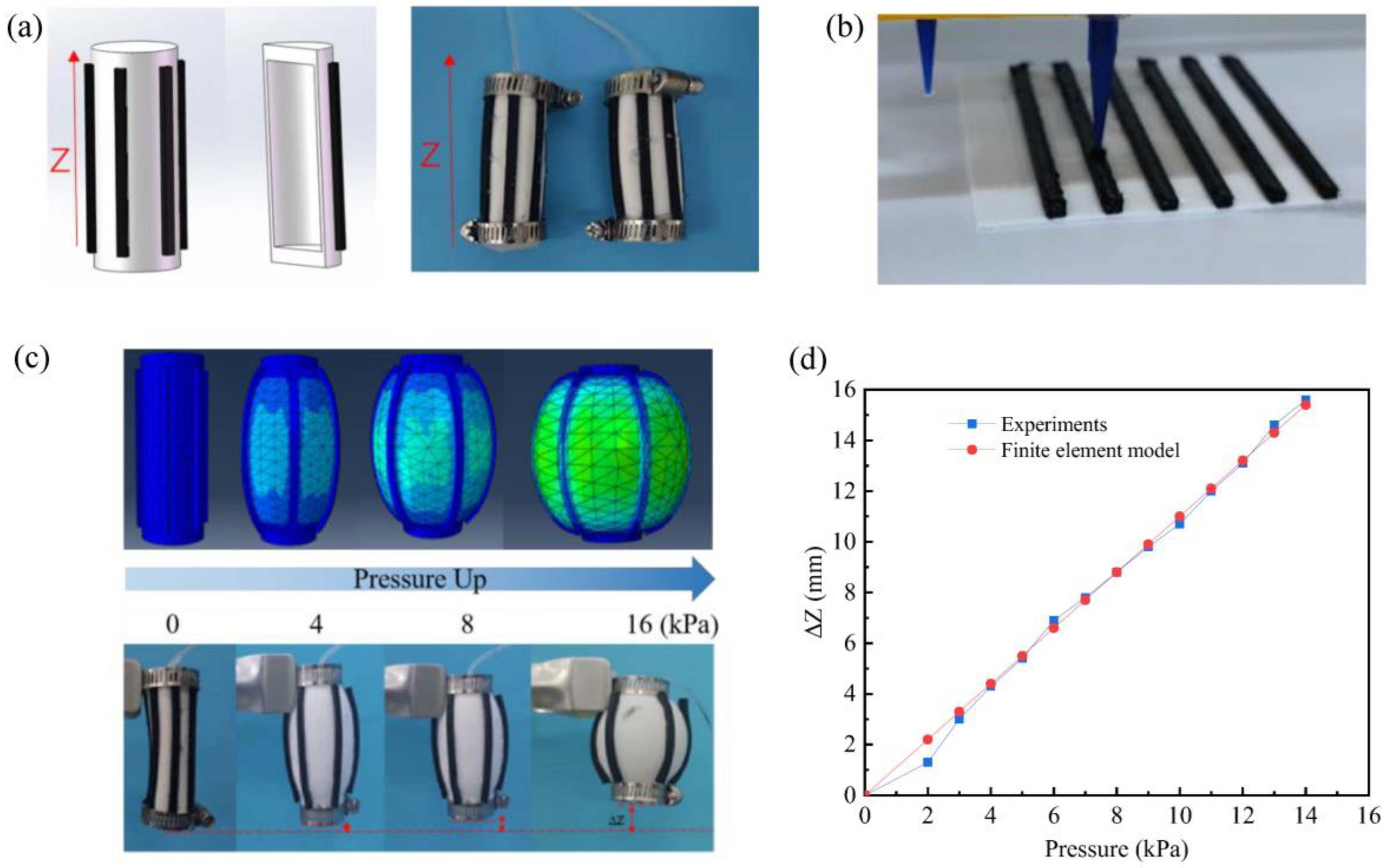
4.1. Artificial Muscle

Based on the above optimal printing parameters, a bionic artificial muscle actuator composed of two materials with different tensile strengths was designed and printed in this paper, as shown in Figure 8a,b. The soft actuator consists of the Ecoflex-0030 cavity cylinder and a DC737 line that limits the free expansion of the Ecoflex-0030. In order to distinguish them, the two silicone materials were mixed with different coloring agents, where the white part is the high elasticity silicone type material Ecoflex-0030, and the black is the relatively low elasticity Dow Corning DC737. This artificial muscle undergoes axial contraction under inflation conditions because the low elasticity of Dow Corning DC737 limits the axial expansion of the air cavity formed by Ecoflex-0030. In addition, building an effective analytical model is meaningful for further understanding the working principle of this artificial muscle (Figure 8c).

4.2. Soft Gripper

For complex solid shapes, it is inevitable to encounter inclination and cavity structures, and the method of performing parametric cavity sealing in soft material 3D printing without internal support is a problem to be solved. Therefore, the proper bridging inclination angle is also critical for solid forming. In this paper, three groups (30°/45°/60°) of bridging angles were considered for simple experiments, and the structure design is shown in Figure 9a.
Under the combination of the above parameters, the bottom view of the bridging seal sample is shown in Figure 9b, with insufficient extrusion leading to severe wire breakage at ζ = 30° and poor high-level bonding leading to part deformation at ζ = 45°, while the structure printed from the bridging transition angle of ζ = 60° is uniform and complete, minimizing defective damage to the bridging joint, thereby mitigating the compression and drag forces caused during the build-up of the filling. The bridging edge deformation caused by compression and drag forces during the build-up filling is reduced. Theoretically, the larger the bridging angle the better, but too large an angle corresponds to more layers and a more pointed top structure, so a reasonable angle is critical in the design. The bridging angle parameters were approximated to 60° for the subsequent example models designed to create a sealed structure for the cavity during 3D printing.
Based on the optimal printing parameters and the above bridging design, a finger pneumatic actuator with complex internal chambers was designed and printed, as shown in Figure 10a–c. The trapezoidal cavity structure is better than the traditional rectangular cavity structure, the advantage being that it can be bent backwards under negative pressure, so that it can grasp larger size objects. As in Figure 10d,e, the soft body gripper and 6 degrees of freedom intelligent robot arm (AUBO-i5 AUBO Intelligent Technology Co., Ltd., Shanghai, China) connected, using the robot arm modular programming controller. Supplemented by a simple circuit control and pressure sensing pneumatic network, you can achieve pulse air pressure control to grasp and put down the object. The experimental setting of air pressure is plus or minus 30 kPa.

5. Conclusions

In summary, we report a comprehensive guide to 3D printing with highly stretchable silicones. Soft material printing is comprehensively introduced through four aspects: platform construction, material property testing, needle modeling simulation and parameter optimization. The highly accurate and rapid printing of soft actuators was realized, and combined with bionic design, artificial muscles and soft grippers were printed directly. With this guide, complex 2D/3D structures composed of soft materials can be printed directly, which could be a promising solution for manufacturing medical prostheses, flexible electronics and soft robots. We believe that this work can provide guidance for further work on printing soft materials using the DIW process in a wide range of application scenarios.

Author Contributions

Conceptualization, J.L.; methodology, J.L.; software, S.W.; data curation, J.L.; formal analysis, S.W.; validation, S.W.; investigation, K.M. and W.Z.; resources, G.J.; writing-original draft preparation, J.L. and S.W.; writing-review and editing, J.L. and S.W.; supervision, J.L.; funding acquisition, G.J. All authors have read and agreed to the published version of the manuscript.

Funding

This work was supported by National Natural Science Foundation of China (Grant No. 61773274).

Conflicts of Interest

The authors declare no conflict of interest.

References

  1. Rus, D.; Tolley, M.T. Design, fabrication and control of soft robots. Nature 2015, 7553, 467–475. [Google Scholar] [CrossRef] [PubMed] [Green Version]
  2. Trivedi, D.; Rahn, C.D.; Kier, W.M.; Walker, I.D. Soft robotics: Biological inspiration, state of the art, and future research. Appl. Bionics Biomech. 2008, 5, 99–117. [Google Scholar] [CrossRef]
  3. Gul, J.Z.; Yang, B.-S.; Yang, Y.J.; Chang, D.E.; Choi, K.H. In situ UV curable 3D printing of multi-material tri-legged soft robot with spider mimicked multi-step forward dynamic gait. Smart Mater. Struct. 2016, 25, 115009. [Google Scholar] [CrossRef]
  4. Gul, J.Z.; Yang, Y.J.; Su, K.Y.; Choi, K.H. Omni directional multimaterial soft cylindrical actuator and its application as a steerable catheter. Soft Robot. 2017, 4, 224–240. [Google Scholar] [CrossRef] [PubMed]
  5. Jones, B.A.; Mcmahan, W.; Walker, I.D. Practical Kinematics for Real-time Implementation of Continuum Robots. In Proceedings of the 2006 IEEE International Conference on Robotics and Automation, ICRA 2006, Orlando, FL, USA, 15–19 May 2006. [Google Scholar] [CrossRef]
  6. Shepherd, R.F.; Ilievski, F.; Choi, W.; Morin, S.A.; Stokes, A.A.; Mazzeo, A.D.; Chen, X.; Wang, M.; Whitesides, G.M. Multigait soft robot. Proc. Natl. Acad. Sci. USA 2011, 108, 20400–20403. [Google Scholar] [CrossRef] [PubMed] [Green Version]
  7. Laschi, C.; Cianchetti, M.; Mazzolai, B.; Margheri, L.; Follador, M.; Dario, P. Soft robot arm inspired by the octopus. Adv. Robot. 2012, 26, 709–727. [Google Scholar] [CrossRef]
  8. Lin, H.T.; Leisk, G.G.; Trimmer, B. Goqbot: A caterpillar-inspired soft-bodied rolling robot. Bioinspiration Biomim. 2011, 6, 026007. [Google Scholar] [CrossRef]
  9. Onal, C.D.; Rus, D. Autonomous undulatory serpentine locomotion utilizing body dynamics of a fluidic soft robot. Bioinspiration Biomim. 2013, 8, 026003. [Google Scholar] [CrossRef]
  10. Marchese, A.D.; Onal, C.D.; Rus, D. Autonomous soft robotic fish capable of escape maneuvers using fluidic elastomer actuators. Soft Robot. 2014, 1, 75. [Google Scholar] [CrossRef] [Green Version]
  11. Mao, S.; Dong, E.; Jin, H.; Xu, M.; Zhang, S.; Yang, J.; Low, K.H. Gait Study and Pattern Generation of a Starfish-Like Soft Robot with Flexible Rays Actuated by SMAs. J. Bionic Eng. 2014, 11, 400–411. [Google Scholar] [CrossRef]
  12. Gu, G.; Zou, J.; Zhao, R.; Zhao, X.; Zhu, X. Soft wall-climbing robots. Sci. Robot. 2018, 3, eaat2874. [Google Scholar] [CrossRef] [PubMed] [Green Version]
  13. Frutiger, A.; Muth, J.T.; Vogt, D.M.; Mengüç, Y.; Campo, A.; Valentine, A.D.; Walsh, C.J.; Lewis, J.A. Capacitive Soft Strain Sensors via Multicore-Shell Fiber Printing. Adv. Mater. 2015, 27, 2440–2446. [Google Scholar] [CrossRef]
  14. Ramuz, M.; Tee, B.C.K.; Tok, J.B.H.; Bao, Z. Transparent, Optical, Pressure-Sensitive Artificial Skin for Large-Area Stretchable Electronics. Adv. Mater. 2012, 24, 3223–3227. [Google Scholar] [CrossRef] [PubMed]
  15. Slyper, R.; Hodgins, J. Prototyping robot appearance, movement, and interactions using flexible 3D printing and air pressure sensors. In Proceedings of the 2012 IEEE RO-MAN: The 21st IEEE International Symposium on Robot and Human Interactive Communication, Paris, France, 9–13 September 2012; pp. 6–11. [Google Scholar] [CrossRef]
  16. Zhou, L.Y.; Gao, Q.; Fu, J.Z.; Chen, Q.Y.; Zhu, J.P.; Sun, Y.; He, Y. Multi-Material 3D Printing of Highly Stretchable Silicone Elastomer. ACS Appl. Mater. Interfaces 2019, 11, 23573–23583. [Google Scholar] [CrossRef] [PubMed]
  17. Truby, R.L.; Lewis, J.A. Printing soft matter in three dimensions. Nature 2016, 540, 371. [Google Scholar] [CrossRef]
  18. Huang, S.H.; Liu, P.; Mokasdar, A.; Hou, L. Additive manufacturing and its societal impact: A literature review. Int. J. Adv. Manuf. Technol. 2013, 67, 1191–1203. [Google Scholar] [CrossRef]
  19. Truby, R.L.; Wehner, M.; Grosskopf, A.K.; Vogt, D.M.; Uzel, S.G.; Wood, R.J.; Lewis, J.A. Soft Somatosensitive Actuators via Embedded 3D Printing. Adv. Mater. 2018, 30, 1706383. [Google Scholar] [CrossRef] [Green Version]
  20. Cheng, Y.; Chan, K.; Wang, X.Q.; Ding, T.; Li, T.; Lu, X.; Ho, G.W. Direct-Ink-Write 3D Printing of Hydrogels into Biomimetic Soft Robots. ACS Nano 2019, 13, 13176–13184. [Google Scholar] [CrossRef]
  21. Kuang, X.; Roach, D.J.; Wu, J.; Hamel, C.M.; Ding, Z.; Wang, T.; Dunn, M.L.; Qi, H.J. Advances in 4D printing: Materials and applications. Adv. Funct. Mater. 2019, 29, 1805290. [Google Scholar] [CrossRef]
  22. Wehner, M.; Truby, R.L.; Fitzgerald, D.J.; Mosadegh, B.; Whitesides, G.M.; Lewis, J.A.; Wood, R.J. An integrated design and fabrication strategy for entirely soft, autonomous robots. Nature 2016, 536, 451–455. [Google Scholar] [CrossRef]
  23. Liang, J.Z. Effects of Extrusion Conditions on Die-Swell Behavior of Polypropylene/Diatomite Composite Melts. Polym. Test. 2008, 27, 936–940. [Google Scholar] [CrossRef]
  24. Wang, K. Die Swell of Complex Polymeric Systems. In Viscoelasticity-From Theory to Biological Applications; IntechOpen: Rijeka, Croatia, 2012; pp. 77–96. [Google Scholar]
  25. Liang, J.-Z. Effect of the Die Angle on the Extrusion Swell of Rubber Compound. J. Mater. Process. Technol. 1995, 52, 207–212. [Google Scholar] [CrossRef]
Figure 1. (a) Soft sensing actuator [19]; (b) tentacle-like soft robot [20]; (c) the swollen flat shape of 3D origami structures and an LED device folded by a flat sheet [21]; (d) soft octopus robot [22].
Actuators 11 00200 g001
Figure 2. (a) Gantry type printing platform; (bd) DIW and component modules.
Actuators 11 00200 g002
Figure 3. (a) Modulus diagram; (b) shear thinning.
Actuators 11 00200 g003
Figure 4. (a) The simulation of conical needle and flow rate and pressure simulation diagram; (b) the simulation of straight tubular needle and flow rate and pressure simulation diagram.
Actuators 11 00200 g004
Figure 5. (a) Schematic illustration of typical parameters for DIW 3D printing; (b) monofilament measurement photos; (c) optical photograph of the fiber shape as a function of speed; (d) frequency histogram chart.
Actuators 11 00200 g005
Figure 6. (a) Model diagram; (b) physical photos; (c) cross-sectional photos.
Actuators 11 00200 g006
Figure 7. (a) Complex 2D structures printed with exemplary silicones; (b) complex 3D structures printed with exemplary silicones.
Actuators 11 00200 g007
Figure 8. (a) Model of artificial muscle; (b) printing process of the artificial muscle; (c) equivalent elastic strain and actual experimental shapes of the artificial muscle; (d) axial contraction under different pressures obtained by the finite element model and experiments.
Actuators 11 00200 g008
Figure 9. (a) Bridging concept and transition inclination angle; (b) Photos of the bridge.
Actuators 11 00200 g009
Figure 10. (a) Printing process of soft gripper; (b) soft gripper dimensioned drawings; (c) bending test; (d) gripping of different objects; (e) experimenting with the gripping process.
Actuators 11 00200 g010aActuators 11 00200 g010b
Publisher’s Note: MDPI stays neutral with regard to jurisdictional claims in published maps and institutional affiliations.

