
Development of a Series Elastic Tendon Actuator (SETA) Based on Gait Analysis for a Knee Assistive Exosuit


Abstract
:1. Introduction
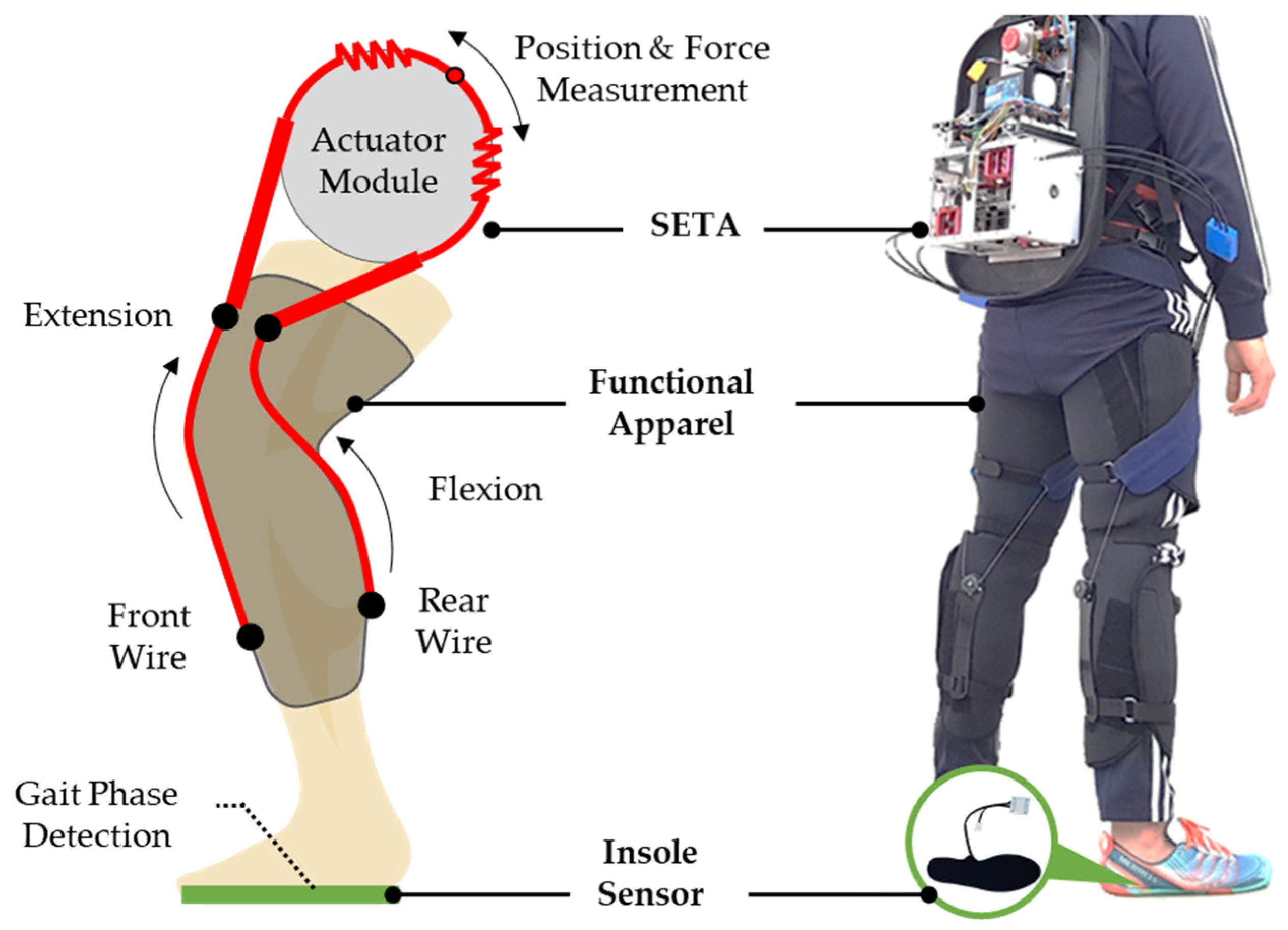
2. Design of SETA
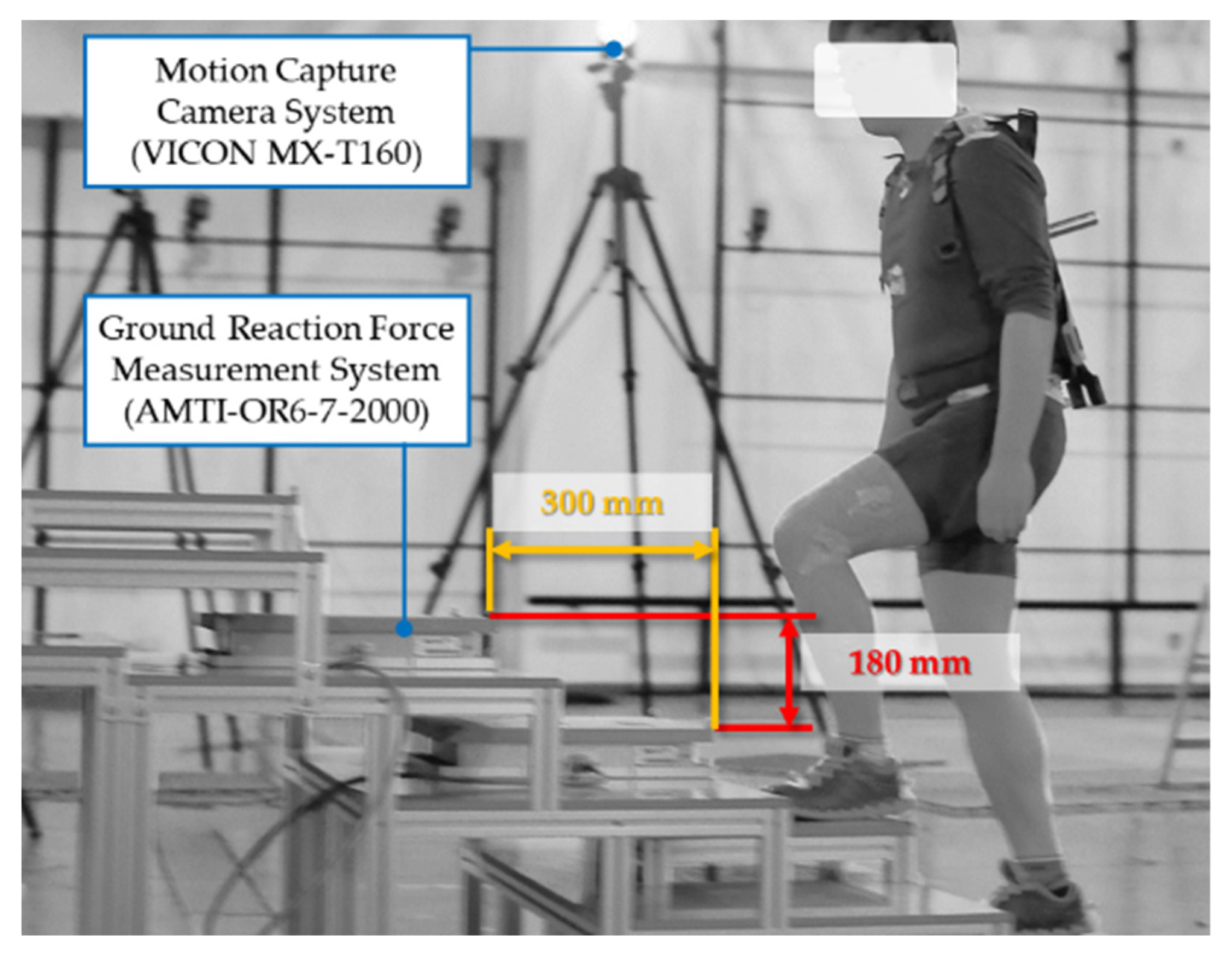
2.1. Experimental Environment for Gait Analysis
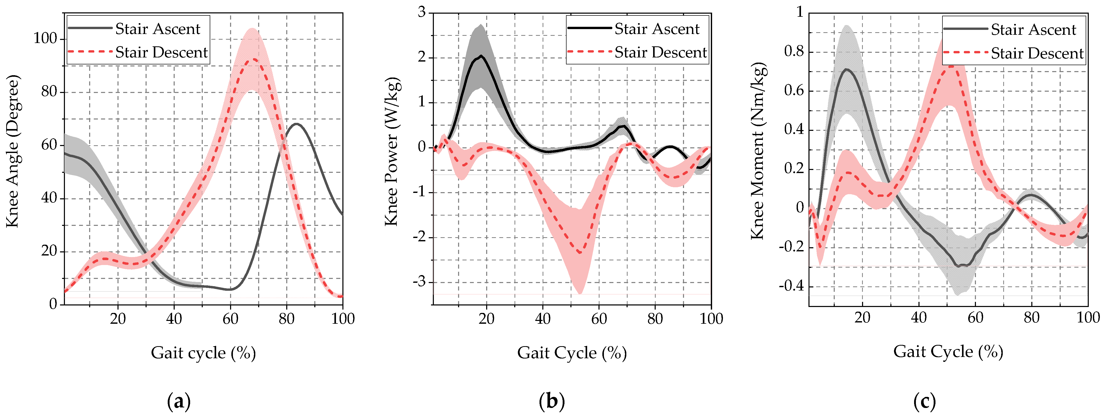
2.2. Gait Analysis Results
2.3. Design Criteria
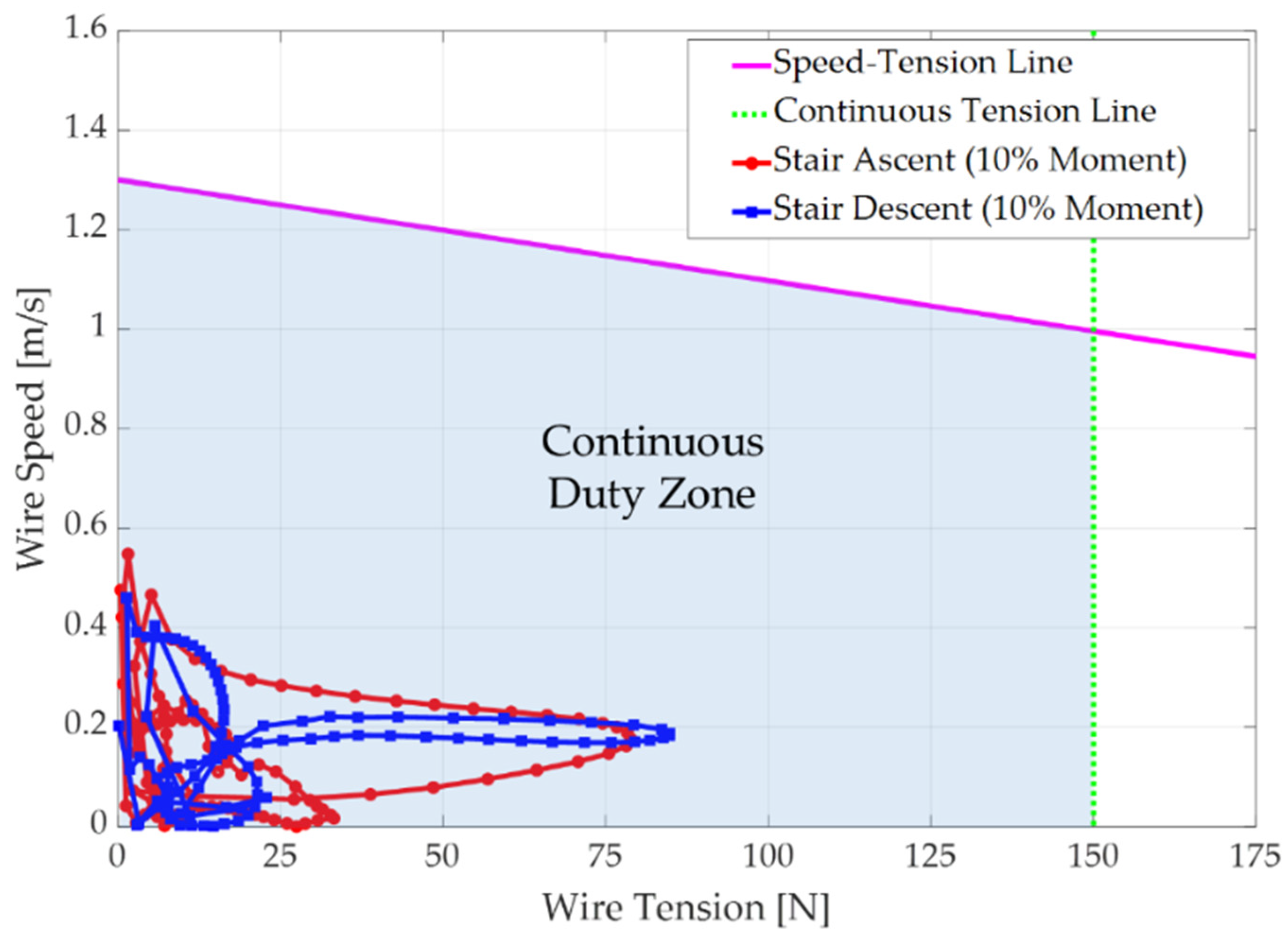
2.4. Required Performance
3. Development of SETA
3.1. Design Concept
3.2. System Sizing
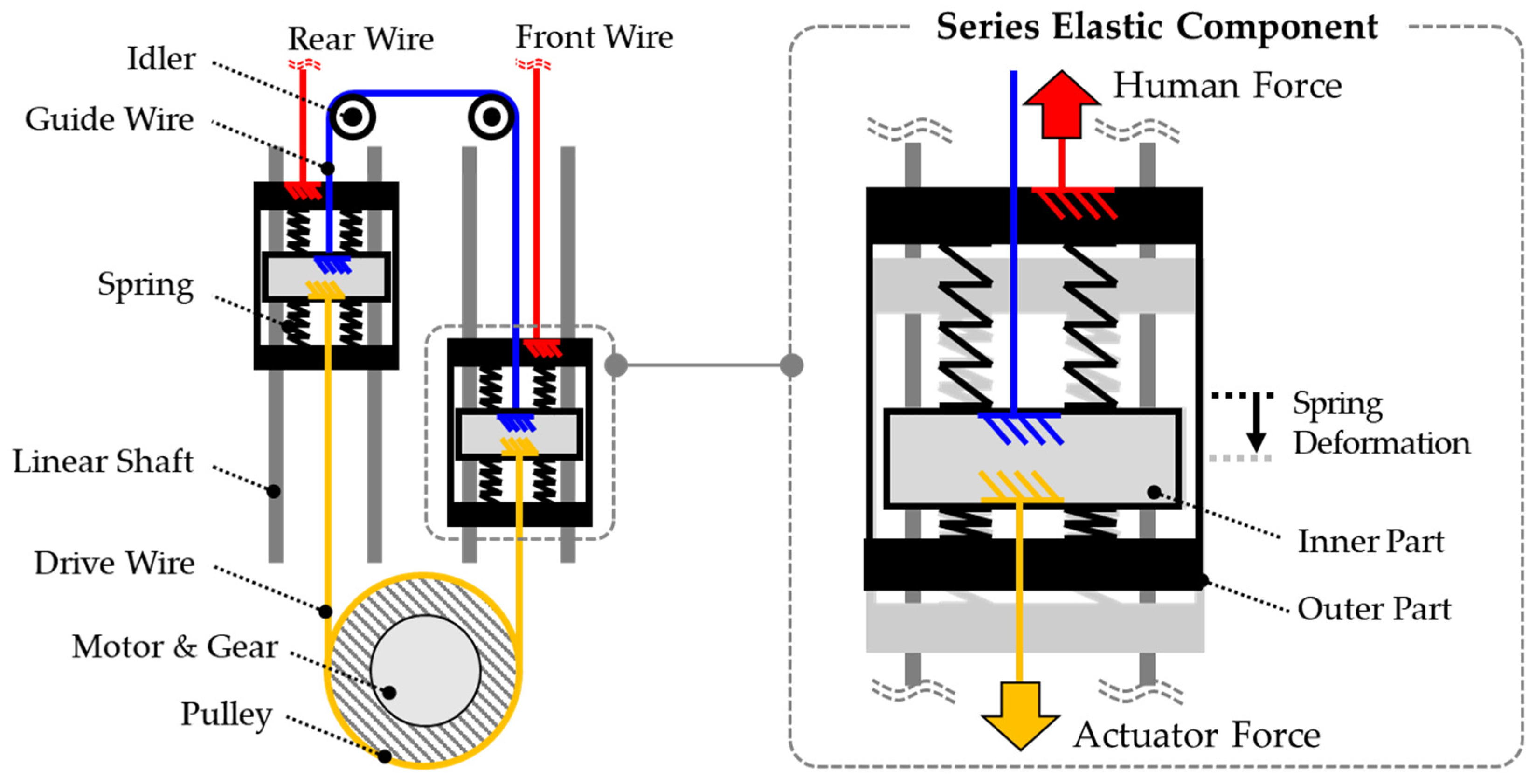
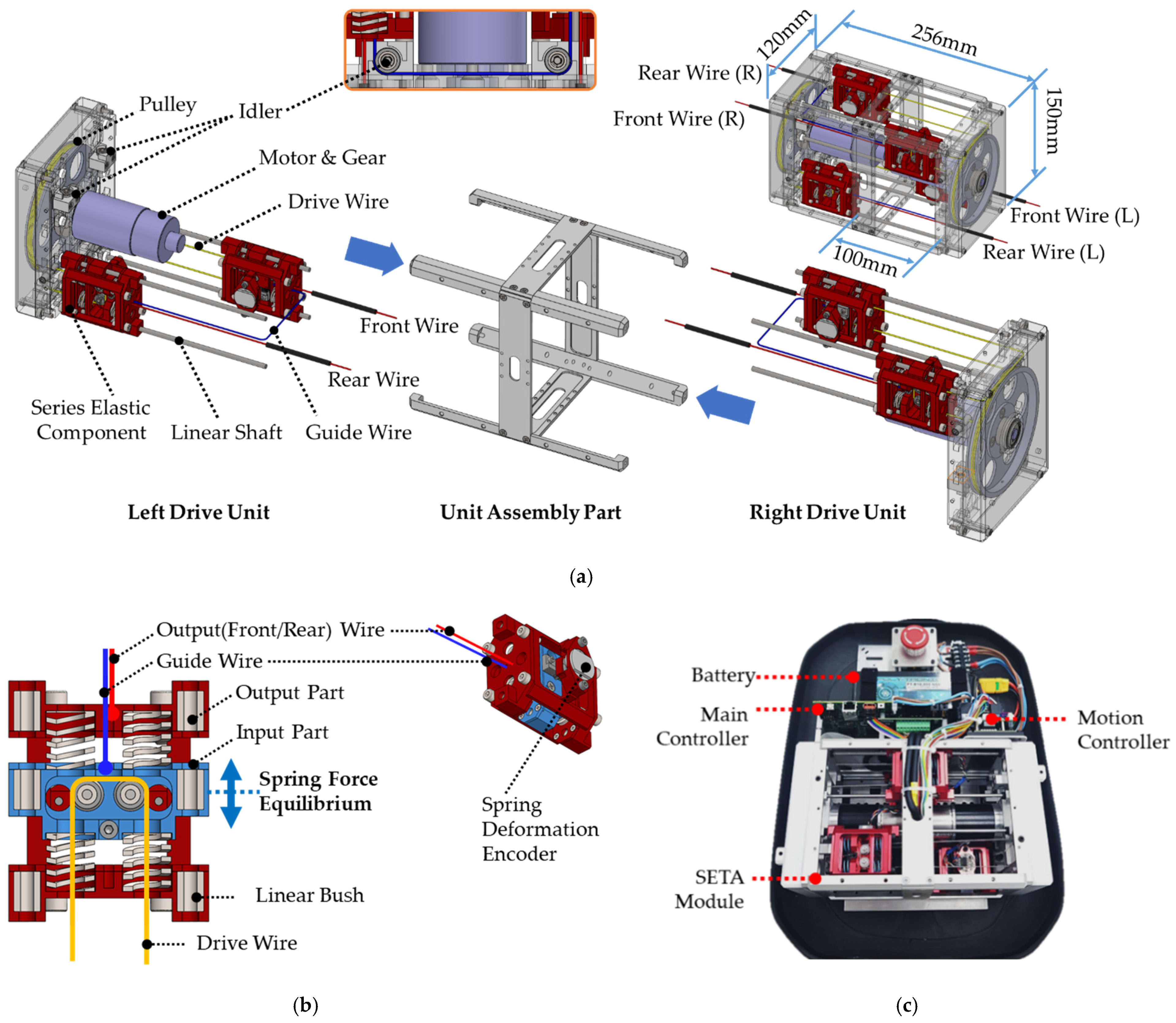
3.3. SETA Design
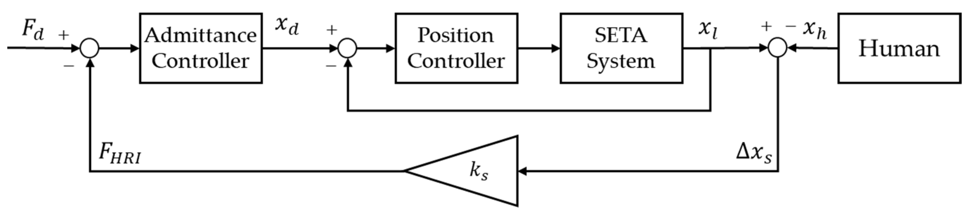
3.4. SETA Control
4. Results
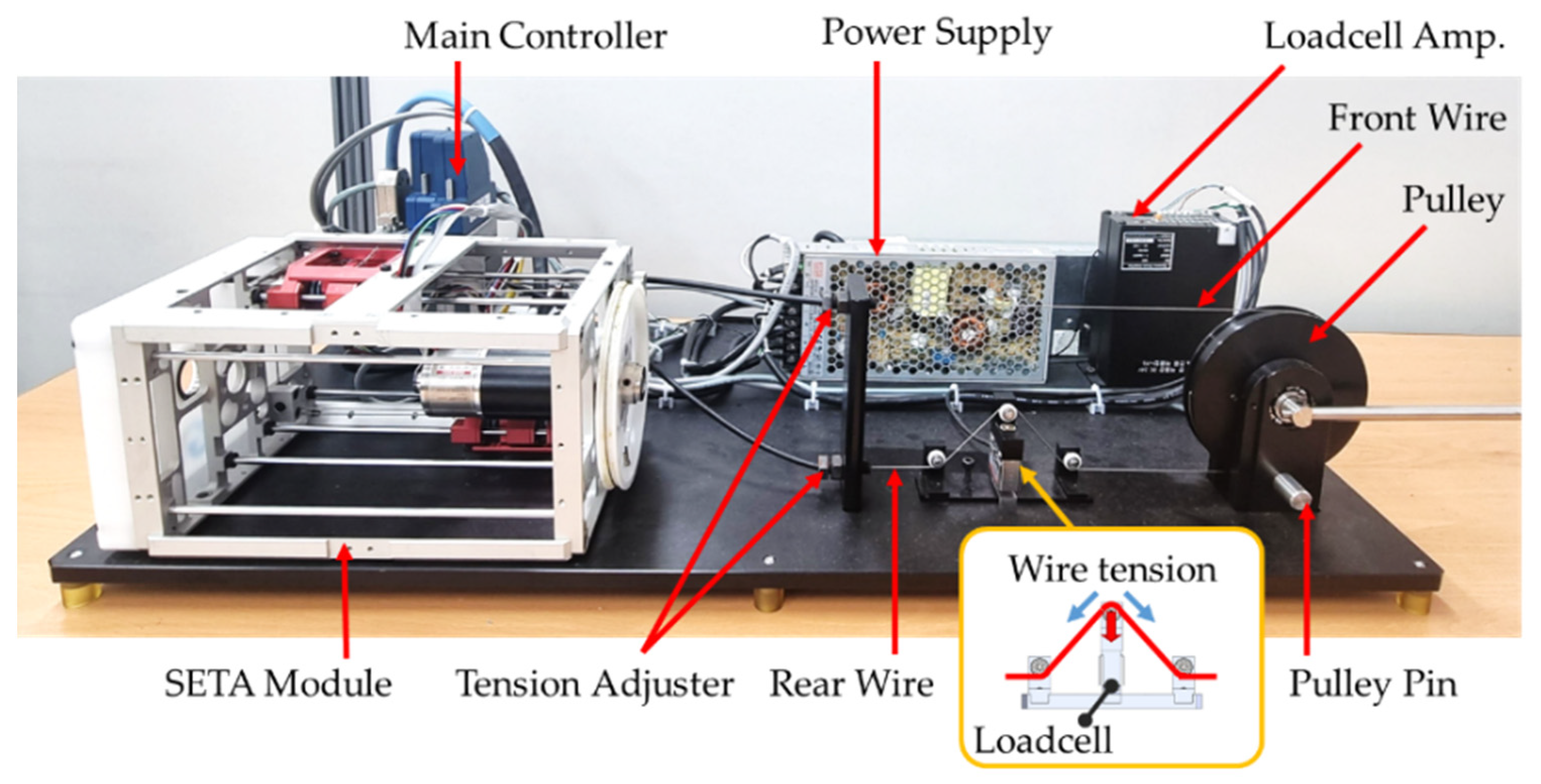
4.1. Experimental Setup
4.2. SEC Deformation Experiments
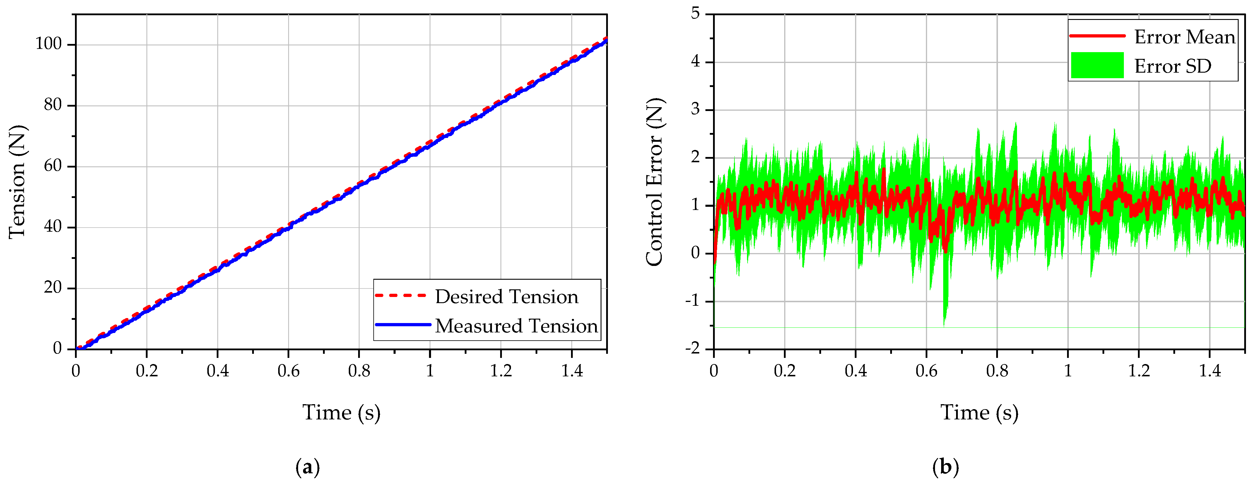
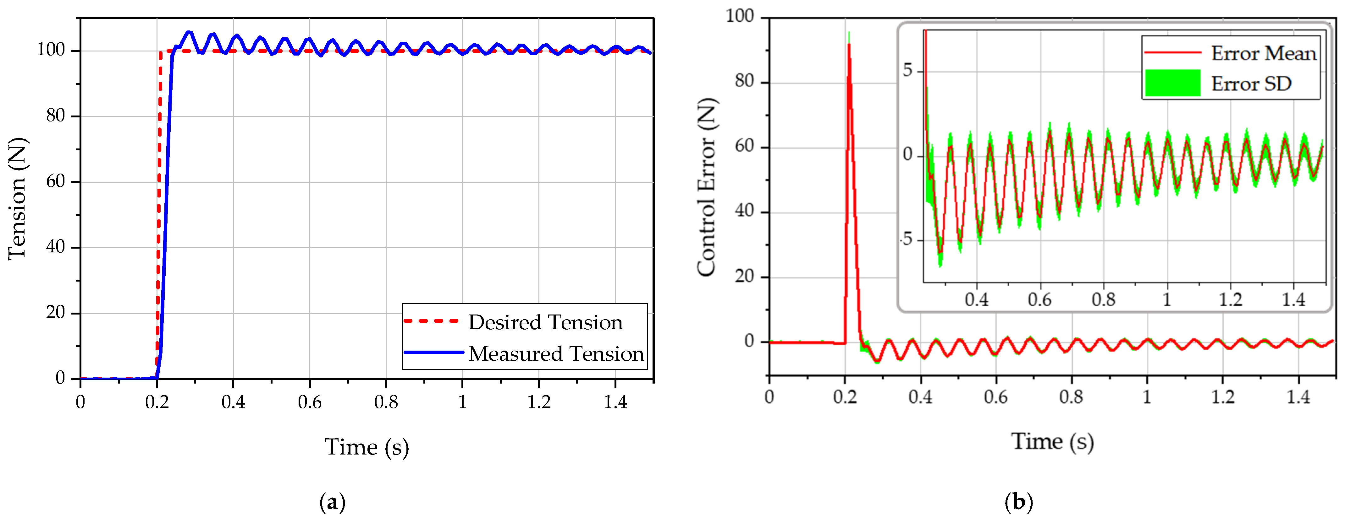
4.3. Force Control Experiments
5. Conclusions
Author Contributions
Funding
Institutional Review Board Statement
Informed Consent Statement
Data Availability Statement
Conflicts of Interest
References
- Kim, W.; Lee, S.; Kang, M.; Han, J.; Han, C. Energy-efficient gait pattern generation of the powered robotic exoskeleton using DME. In Proceedings of the IEEE/RSJ 2010 International Conference on Intelligent Robots and Systems, Taipei, Taiwan, 18–22 October 2010; pp. 2475–2480. [Google Scholar]
- Lee, H.; Kim, W.; Han, J.; Han, C. The technical trend of the exoskeleton robot system for human power assistance. Intl. J. Prec. Eng. Manuf. 2012, 13, 1491–1497. [Google Scholar] [CrossRef]
- Li, H.; Cheng, W.; Liu, F.; Zhang, M.; Wang, K. The effects on muscle activity and discomfort of varying load carriage with and without an augmentation exoskeleton. Appl. Sci. 2018, 8, 2638. [Google Scholar] [CrossRef] [Green Version]
- Zoss, A.B.; Kazerooni, H.; Chu, A. Biomechanical design of the Berkeley lower extremity exoskeleton (BLEEX). IEEE/ASME Trans. Mech. 2006, 11, 128–138. [Google Scholar] [CrossRef]
- Hyun, D.J.; Park, H.; Ha, T.; Park, S.; Jung, K. Biomechanical design of an agile, electricity–powered lower-limb exoskeleton for weight-bearing assistance. Robot. Auton. Syst. 2017, 95, 181–195. [Google Scholar] [CrossRef]
- Asbeck, A.T.; De Rossi, S.M.M.; Holt, K.G.; Walsh, C.J. A biologically inspired soft exosuit for walking assistance. Int. J. Robot. Res. 2015, 34, 744–762. [Google Scholar] [CrossRef]
- Schmidt, K.; Duarte, J.E.; Grimmer, M.; Sancho-Puchades, A.; Wei, H.; Easthope, C.S.; Riener, R. The myosuit: Bi-articular anti-gravity exosuit that reduces hip extensor activity in sitting transfers. Front. Neurorobot. 2017, 11, 57. [Google Scholar] [CrossRef] [Green Version]
- Lee, H.D.; Park, H.; Seongho, B.; Kang, T.H. Development of a Soft Exosuit System for Walking Assistance During Stair Ascent and Descent. Int. J. Con. Autom. Syst. 2020, 18, 2678–2686. [Google Scholar] [CrossRef]
- Park, E.J.; Akbas, T.; Eckert-Erdheim, A.; Sloot, L.H.; Nuckols, R.W.; Orzel, D.; Schumm, L.; Ellis, T.D.; Awad, L.N.; Walsh, C.J. A Hinge-Free, Non-Restrictive, Lightweight Tethered Exosuit for Knee Extension Assistance During Walking. IEEE Trans. Med. Robot. Bionics 2020, 2, 165–175. [Google Scholar] [CrossRef]
- Bae, J.; Awad, L.N.; Long, A.; O’Donnell, K.; Hendron, K.; Holt, K.G.; Ellis, T.D.; Walsh, C.J. Biomechanical mechanisms underlying exosuit-induced improvements in walking economy after stroke. J. Exp. Biol. 2018, 221, jeb168815. [Google Scholar] [CrossRef] [Green Version]
- Sridar, S.; Qiao, Z.; Muthukrishnan, N.; Zhang, W.; Polygerinos, P.A. Soft-Inflatable Exosuit for Knee Rehabilitation: Assisting Swing Phase During Walking. Front. Robot. AI 2018, 5, 44. [Google Scholar] [CrossRef] [Green Version]
- Xiloyannis, M.; Chiaradia, D.; Frisoli, A.; Masia, L. Physiological and kinematic effects of a soft exosuit on arm movements. J. NeuroEng. Rehab. 2019, 16, 29. [Google Scholar] [CrossRef] [PubMed]
- Asbeck, A.T.; Dyer, R.J.; Larusson, A.F.; Walsh, C.J. Biologically-inspired soft exosuit. In Proceedings of the 2013 IEEE 13th International Conference on Rehabilitation Robotics (ICORR), Seattle, WA, USA, 24–26 June 2013; pp. 1–8. [Google Scholar]
- Hu, B.; Zhang, F.; Lu, H.; Zou, H.; Yang, J.; Yu, H. Design and assist-as-needed control of flexible elbow exoskeleton actuated by nonlinear series elastic cable driven mechanism. Actuators 2021, 10, 290. [Google Scholar] [CrossRef]
- Quinlivan, B.T.; Lee, S.; Malcolm, P.; Rossi, D.M.; Grimmer, M.; Siviy, C.; Karavas, N.; Wagner, D.; Asbeck, A.; Galiana, I.; et al. Assistance magnitude versus metabolic cost reductions for a tethered multiarticular soft exosuit. Sci. Robot. 2017, 2, eaah4416. [Google Scholar] [CrossRef]
- Zhang, T.; Huang, H. Design and Control of a Series Elastic Actuator with Clutch for Hip Exoskeleton for Precise Assistive Magnitude and Timing Control and Improved Mechanical Safety. IEEE/ASME Trans. Mech. 2019, 24, 2215–2226. [Google Scholar] [CrossRef]
- Ding, Y.; Panizzolo, F.A.; Siviy, C.; Malcolm, P.; Galiana, I.; Holt, K.G.; Walsh, C.J. Effect of timing of hip extension assistance during loaded walking with a soft exosuit. J. Neuroeng. Rehab. 2016, 13, 87. [Google Scholar] [CrossRef] [Green Version]
- Oh, S.; Kong, K. High-Precision Robust Force Control of a Series Elastic Actuator. IEEE/ASME Trans. Mech. 2017, 22, 71–80. [Google Scholar] [CrossRef]
- Veale, A.J.; Xie, S.Q. Towards compliant and wearable robotic orthoses: A review of current and emerging actuator technologies. Med. Eng. Phys. 2016, 38, 317–325. [Google Scholar] [CrossRef]
- Zhang, T.; Tran, M.; Huang, H. Design and experimental verification of hip exoskeleton with balance capacities for walking assistance. IEEE/ASME Trans. Mech. 2018, 23, 274–285. [Google Scholar] [CrossRef]
- Giovacchini, F.; Vannetti, F.; Fantozzi, M.; Cempini, M.; Cortese, M.; Parri, A.; Yan, T.; Lefeber, D.; Vitiello, N. A light-weight active orthosis for hip movement assistance. Robot. Auton. Syst. 2015, 73, 123–134. [Google Scholar] [CrossRef]
- Yu, H.; Huang, S.; Chen, G.; Pan, Y.; Guo, Z. Human-Robot Interaction Control of Rehabilitation Robots with Series Elastic Actuators. IEEE Trans. Robot. 2015, 31, 1089–1100. [Google Scholar] [CrossRef]
- Kim, S.; Bae, J. Force-mode control of rotary series elastic actuators in a lower extremity exoskeleton using model-inverse time delay control. IEEE/ASME Trans. Mech. 2017, 22, 1392–1400. [Google Scholar] [CrossRef]
- Liu, X.; Wang, Q. Real-Time Locomotion Mode Recognition and Assistive Torque Control for Unilateral Knee Exoskeleton on Different Terrains. IEEE/ASME Trans. Mech. 2020, 25, 2722–2732. [Google Scholar] [CrossRef]
- Yu, S.; Huang, T.H.; Yang, X.; Jiao, C.; Yang, J.; Hu, H.; Zhang, S.; Chen, Y.; Yi, J.; Su, H. Quasi-direct drive actuation for a lightweight hip exoskeleton with high backdrivability and high bandwidth. arXiv 2020, 25, 1794–1802. [Google Scholar] [CrossRef] [PubMed]
- Pratt, G.A.; Williamson, M.M. Series elastic actuators. In Proceedings of the 1995 IEEE/RSJ International Conference on Intelligent Robots and Systems, Human Robot Interaction and Cooperative Robots, Pittsburgh, PA, USA, 5–9 August 1995; pp. 399–406. [Google Scholar]
- Lee, H.D.; Moon, J.I.; Kang, T.H. Design of a Series Elastic Tendon Actuator Based on Gait Analysis for a Walking Assistance Exosuit. Int. J. Con. Autom. Syst. 2019, 17, 2940–2947. [Google Scholar] [CrossRef]
- Dinh, B.K.; Xiloyannis, M.; Cappello, L.; Antuvan, C.W.; Yen, S.C.; Masia, L. Adaptive backlash compensation in upper limb soft wearable exoskeletons. Robot. Auton. Syst. 2017, 92, 173–186. [Google Scholar] [CrossRef]
- Karavas, N.; Kim, J.; Galiana, I.; Ding, Y.; Couture, A.; Wagner, D.; Eckert-Erdheim, A.; Walsh, C. Autonomous soft exosuit for hip extension assistance. In Wearable Robotics: Challenges and Trends; Springer: New York, NY, USA, 2017; pp. 331–335. ISBN 978-3-319-46531-9. [Google Scholar]
- Ding, Y.; Galiana, I.; Asbeck, A.; De Rossi, S.; Bae, J.; Santos, T.; Araujo, V.; Lee, S.; Holt, K.; Walsh, C.J. Biomechanical and Physiological Evaluation of Multi-joint Assistance with Soft Exosuits. IEEE Trans. Neural Syst. Rehabil. Eng. 2016, 25, 119–130. [Google Scholar] [CrossRef] [PubMed]
- Cappello, L.; Binh, D.K.; Yen, S.C.; Masia, L. Design and preliminary characterization of a soft wearable exoskeleton for upper limb. In Proceedings of the IEEE International Conference on Biomedical Robotics and Biomechatronics (BioRob), Singapore, 26–29 June 2016; pp. 623–630. [Google Scholar]
- Pons, J.L. Wearable Robots: Biomechatronic Exoskeletons; John Wiley & Sons: New York, NY, USA, 2008. [Google Scholar]
- Kim, W.; Lee, H.; Kim, D.; Han, J.; Han, C. Mechanical design of the Hanyang Exoskeleton Assistive Robot (HEXAR). In Proceedings of the 2014 14th International Conference on Control, Automation and Systems (ICCAS 2014), Gyeonggi-do, Korea, 22–25 October 2014; pp. 479–484. [Google Scholar]
- Zoss, A.; Kazerooni, H. Design of an electrically actuated lower extremity exoskeleton. Adv. Robot. 2006, 20, 967–988. [Google Scholar] [CrossRef] [Green Version]
- Ding, Y.; Galiana, I.; Asbeck, A.; Quinlivan, B.; Marco, S.; De Rossi, M.; Walsh, C. Multi-joint Actuation Platform for Lower Extremity Soft Exosuits. In Proceedings of the 2014 IEEE International Conference on Robotics and Automation (ICRA), Hong Kong, China, 31 May–7 June 2014; pp. 1327–1334. [Google Scholar]
- Buchanan, T.S.; Lloyd, D.G.; Manal, K.; Besier, T.F. Neuromusculoskeletal modeling: Estimation of muscle forces and joint moments and movements from measurements of neural command. J. Appl. Biomech. 2004, 20, 367–395. [Google Scholar] [CrossRef] [Green Version]


| Parameters | Max. (Mean/SD) | Min. (Mean/SD) | Unit |
|---|---|---|---|
| Angle | 92.7/11.7 | 3.1/0.7 | ° |
| Moment | 0.73/0.203 | −0.29/0.137 | Nm/kg |
| Power | 2.04/0.708 | −2.34/0.945 | W/kg |
| Requirements | Value | Unit |
|---|---|---|
| Maximum wire tension | 100 | N |
| Maximum wire speed | 0.6 | m/s |
| Wire operating range | 100 | mm |
| Motor | ) | 36 V |
| ) | 1.71 A | |
| ) | 28.6 A | |
| ) | 46.1 mNm/A | |
| ) | 207 rpm/V | |
| Gear | ) | 30 |
| ) | 81% | |
| ) | 7.5 Nm | |
| Pulley | ) | 50 mm |
Publisher’s Note: MDPI stays neutral with regard to jurisdictional claims in published maps and institutional affiliations. |
© 2022 by the authors. Licensee MDPI, Basel, Switzerland. This article is an open access article distributed under the terms and conditions of the Creative Commons Attribution (CC BY) license (https://creativecommons.org/licenses/by/4.0/).
Share and Cite
Lee, H.D.; Park, H.; Hong, D.H.; Kang, T.H. Development of a Series Elastic Tendon Actuator (SETA) Based on Gait Analysis for a Knee Assistive Exosuit. Actuators 2022, 11, 166. https://doi.org/10.3390/act11060166
Lee HD, Park H, Hong DH, Kang TH. Development of a Series Elastic Tendon Actuator (SETA) Based on Gait Analysis for a Knee Assistive Exosuit. Actuators. 2022; 11(6):166. https://doi.org/10.3390/act11060166
Chicago/Turabian StyleLee, Hee Don, Heejin Park, Dae Han Hong, and Tae Hun Kang. 2022. "Development of a Series Elastic Tendon Actuator (SETA) Based on Gait Analysis for a Knee Assistive Exosuit" Actuators 11, no. 6: 166. https://doi.org/10.3390/act11060166