
Cable-Driven Parallel Robot Actuators: State of the Art and Novel Servo-Winch Concept

Abstract
:1. Introduction
2. Servo-Winch State of the Art
- Cable overlapping on the drum surface should be avoided, which can be done, for example, by grooving the drum to accommodate the cable (this is also desirable for reducing cable wear [57]);
- The cable should exit the drum in a fixed, known direction.
2.1. The Rototranslating-Drum Design
2.2. The Spooling-Helper Design
2.3. The Translating-Motor Design
3. The Spline Winch
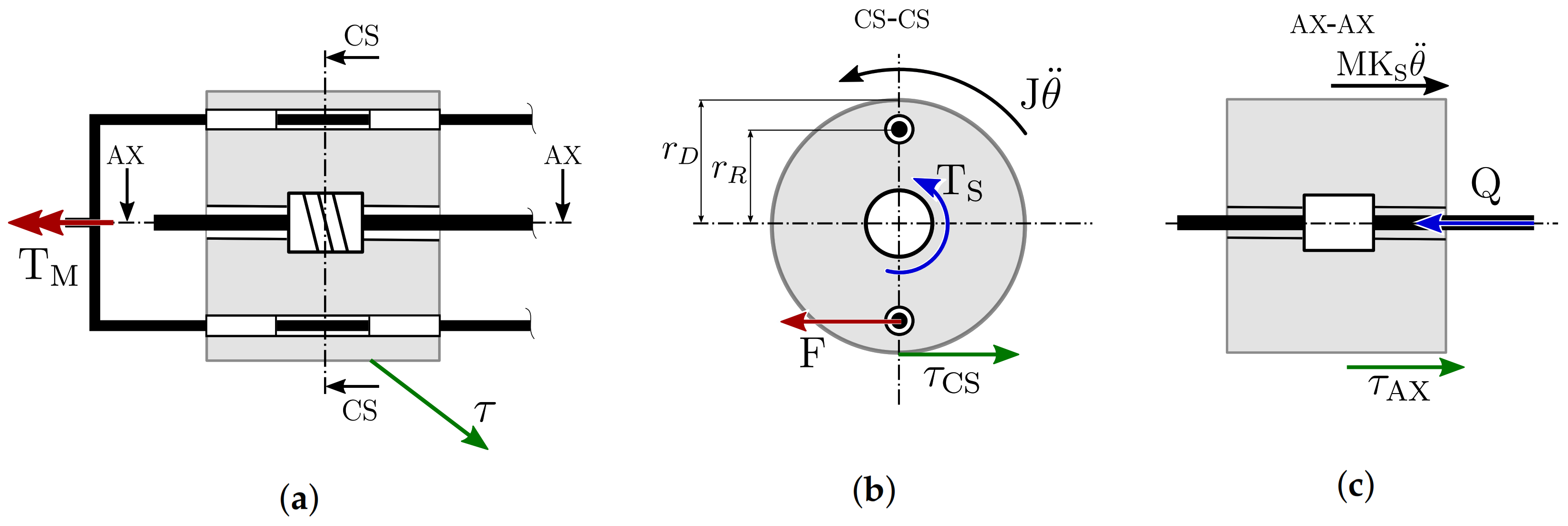
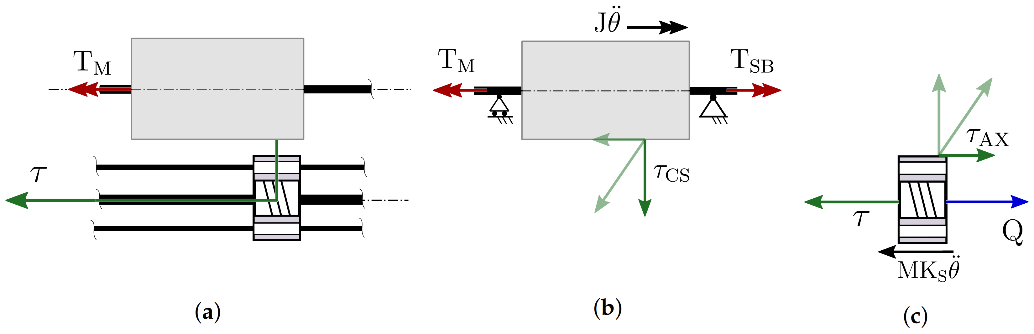
3.1. Kinematics
- Rotate since a spline shaft is rigidly attached to the motor axis, and a spline nut is attached to the drum; the spline shaft/nut pair is effectively a prismatic joint (P), designed so as to transmit torque while allowing axial translation;
- Translate since a screw shaft is rigidly attached to the winch frame, and a screw nut is attached to the drum; this is the classical helical pair (H) used in all winch designs.
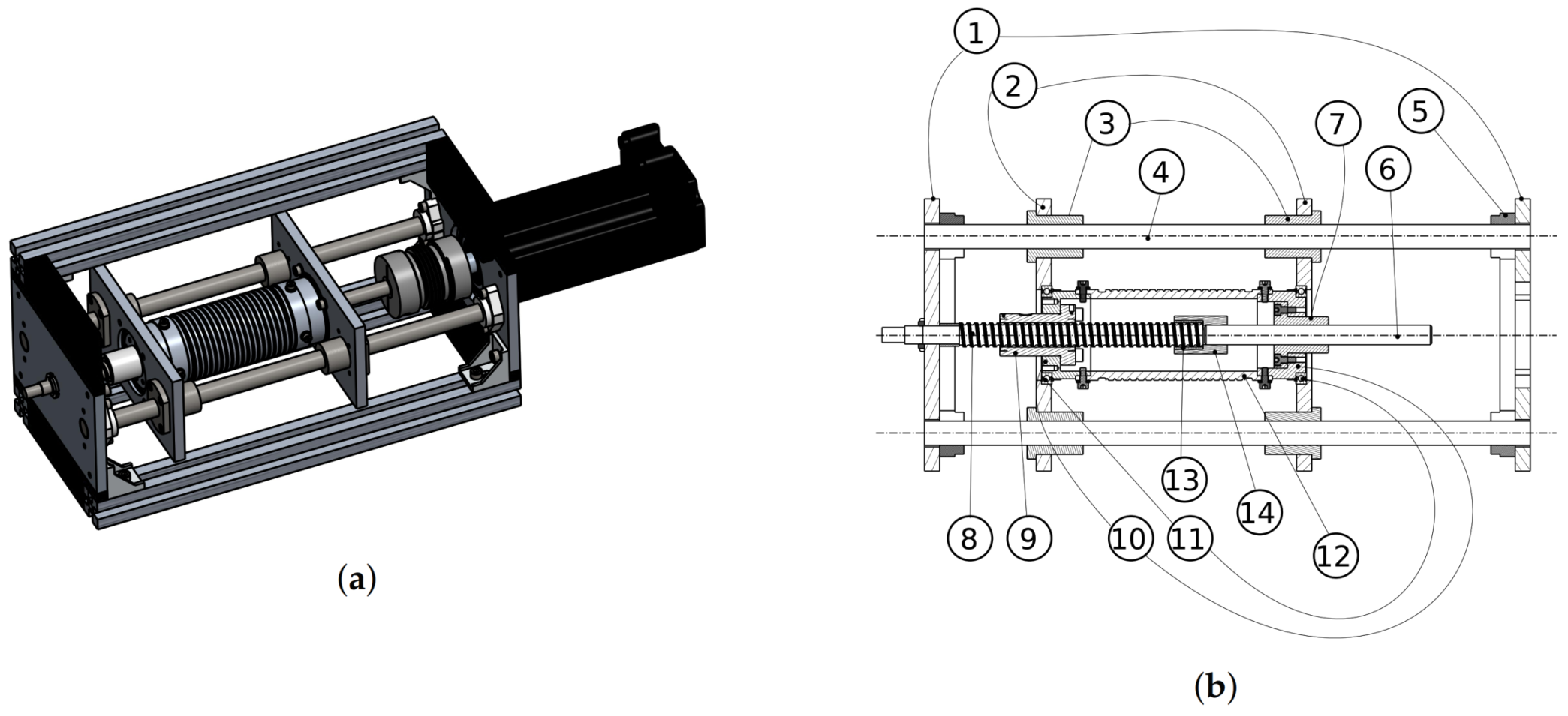
3.2. Mechanical Design
4. Design Comparison and Application Guidelines
- The rototranslating-drum design, though conceptually simple, suffers from three main drawbacks:
- -
- To transmit torque to the drum, the shafts that pass through the winches are subject to a radial force which may be critically higher than the cable tension by design since ; this means that these shafts need to be bulky enough, which in turns means that the drum radius (and thus the transmission ratio) cannot vary freely.
- -
- If an open-end design of the shafts is employed, such as the one proposed in Figure 2a, the torsional load of the winch may deform the rods without actually transmitting force to the drum.
- -
- The manufacturing tolerance of the shaft, the drum, and the bushing inside the drum, need to be very high in order to avoid the winch stalling [38]; this, in turn, highlights that the mechanical design should be everything but simple.
Its primary advantage is the possibility to freely install the winch in any configuration since its dynamics is only affected by the drum weight, which can be very low. - The translating motor winch has three significant advantages, namely:
- -
- It can be easily miniaturized since it has no components passing through the drum other than the screw;
- -
- It is mechanically straightforward (most of the components for its manufacturing are commercially available), and thus also cheap;
- -
- It is structurally efficient since the rods withstanding the external load (but possibly also the motor weight) can be placed in a convenient position, and be as sturdy as needed since .
On the other hand, its main characteristic is also its main drawback: the motor (and gearbox, if used) mass needs to be translated with the drum, which means that:- -
- According to Equation (11), the overall transmission inertia may be critically high since M includes both the drum and the winch mass, thus severely limiting winch dynamics;
- -
- If the winch is installed with its axis vertical, the weight of both the motor and the drum has to be compensated by the motor torque, which is not very efficient.
- As previously mentioned, the Spline Winch attempts to summarize the rototranslating-drum and translating-motor winches’ advantages, while not suffering from the drawbacks:
- -
- As the rototranslating-drum design, it can be freely installed because it does not have to carry the motor weight around, even though it needs to compensate for the two additional translating plates (and bearings) as a trade-off;
- -
- As the translating-motor design, it can be miniaturized (small screw and spline shaft are commercially available). The additional mechanical complexities are the spline shaft and the motor-shaft-spline-shaft coupling, which is commercially available and structurally efficient.
It does not suffer from any rototranslating-drum and translating-motor design drawbacks, but it strictly requires two more components: the spline shaft and the motor-shaft-spline-shaft coupling. This means that it may not be as cheap and small as the translating-motor design.
5. Conclusions
Author Contributions
Funding
Institutional Review Board Statement
Informed Consent Statement
Data Availability Statement
Acknowledgments
Conflicts of Interest
References
- Mattioni, V.; Idà, E.; Carricato, M. Design of a Planar Cable-Driven Parallel Robot for Non-Contact Tasks. Appl. Sci. 2021, 11, 9491. [Google Scholar] [CrossRef]
- Gagliardini, L.; Caro, S.; Gouttefarde, M.; Girin, A. Discrete reconfiguration planning for Cable-Driven Parallel Robots. Mech. Mach. Theory 2016, 100, 313–337. [Google Scholar] [CrossRef] [Green Version]
- Heyden, T.; Woernle, C. Dynamics and flatness-based control of a kinematically undetermined cable suspension manipulator. Multibody Syst. Dyn. 2006, 16, 155. [Google Scholar] [CrossRef]
- Mattioni, V.; Idà, E.; Carricato, M. Force-distribution sensitivity to cable-tension errors in overconstrained cable-driven parallel robots. Mech. Mach. Theory 2022, 175, 104940. [Google Scholar] [CrossRef]
- Kraus, W.; Spiller, A.; Pott, A. Energy efficiency of cable-driven parallel robots. In Proceedings of the 2016 IEEE International Conference on Robotics and Automation (ICRA), (ICRA) OR International Conference on Robotics and Automation, Stockholm, Sweden, 16–21 May 2016; pp. 894–901. [Google Scholar]
- Bruckmann, T.; Sturm, C.; Fehlberg, L.; Reichert, C. An energy-efficient wire-based storage and retrieval system. In Proceedings of the 2013 IEEE/ASME International Conference on Advanced Intelligent Mechatronics, Wollongong, Australia, 9–12 July 2013; pp. 631–636. [Google Scholar]
- Iturralde, K.; Feucht, M.; Illner, D.; Hu, R.; Pan, W.; Linner, T.; Bock, T.; Eskudero, I.; Rodriguez, M.; Gorrotxategi, J.; et al. Cable-driven parallel robot for curtain wall module installation. Autom. Constr. 2022, 138, 104235. [Google Scholar] [CrossRef]
- Bettega, J.; Richiedei, D.; Trevisani, A. Using Pose-Dependent Model Predictive Control for Path Tracking with Bounded Tensions in a 3-DOF Spatial Cable Suspended Parallel Robot. Machines 2022, 10, 453. [Google Scholar] [CrossRef]
- Lin, D.; Mottola, G.; Carricato, M.; Jiang, X.; Li, Q. Dynamically-Feasible Trajectories for a Cable-Suspended Robot Performing Throwing Operations. In ROMANSY 23—Robot Design, Dynamics and Control; Venture, G., Solis, J., Takeda, Y., Konno, A., Eds.; Springer International Publishing: Cham, Switzerland, 2021; pp. 547–555. [Google Scholar]
- Martin, A.; Caro, S.; Cardou, P. Geometric determination of the cable-cylinder interference regions in the workspace of a cable-driven parallel robot. In Cable-Driven Parallel Robots; Springer: Berlin, Germany, 2018; pp. 117–127. [Google Scholar]
- Idà, E.; Briot, S.; Carricato, M. Robust Trajectory Planning of Under-Actuated Cable-Driven Parallel Robot with 3 Cables. In Advances in Robot Kinematics 2020; Lenarčič, J., Siciliano, B., Eds.; Springer International Publishing: Cham, Switzerland, 2021; pp. 65–72. [Google Scholar]
- Idà, E.; Carricato, M. A New Performance Index for Underactuated Cable-Driven Parallel Robots. In Cable-Driven Parallel Robots; Gouttefarde, M., Bruckmann, T., Pott, A., Eds.; Springer International Publishing: Cham, Switzerland, 2021; pp. 24–36. [Google Scholar]
- Cone, L.L. Skycam-an aerial robotic camera system. Byte 1985, 10, 122. [Google Scholar]
- Higuchi, T.; Ming, A.; Jiang-Yu, J. Application of Multi-Dimensional Wire Cranes in Construction. In Proceedings of the 5th International Symposium on Automation and Robotics in Construction (ISARC), International Association for Automation and Robotics in Construction (IAARC), Tokyo, Japan, June 1988; pp. 661–668. [Google Scholar]
- Albus, J.; Bostelman, R.; Dagalakis, N. The NIST robocrane. J. Natl. Inst. Stand. Technol. 1992, 10, 709–724. [Google Scholar] [CrossRef]
- Tho, T.P.; Thinh, N.T. Using a Cable-Driven Parallel Robot with Applications in 3D Concrete Printing. Appl. Sci. 2021, 11, 563. [Google Scholar] [CrossRef]
- Williams, R.L., II; Xin, M.; Bosscher, P. Contour-crafting-cartesian-cable robot system: Dynamics and controller design. In Proceedings of the ASME 2008 International Design Engineering Technical Conferences, New York, NY, USA, 3–6 August 2008; Volume 2, pp. 39–45. [Google Scholar]
- Lv, W.; Tao, L.; Ji, Z. Design and control of cable-drive parallel robot with 6-dof active wave compensation. In Proceedings of the 2017 3rd International Conference on Control, Automation and Robotics (ICCAR), Nagoya, Japan, 22–24 April 2017; pp. 129–133. [Google Scholar]
- Pott, A.; Meyer, C.; Verl, A. Large-scale assembly of solar power plants with parallel cable robots. In Proceedings of the ISR 2010 (41st International Symposium on Robotics) and ROBOTIK 2010 (6th German Conference on Robotics), Munich, Germany, 7–9 June 2010; pp. 1–6. [Google Scholar]
- Culla, D.; Gorrotxategi, J.; Rodríguez, M.; Izard, J.B.; Hervé, P.E.; Cañada, J. Full Production Plant Automation in Industry Using Cable Robotics with High Load Capacities and Position Accuracy. In ROBOT 2017: Third Iberian Robotics Conference; Ollero, A., Sanfeliu, A., Montano, L., Lau, N., Cardeira, C., Eds.; Springer International Publishing: Cham, Switzerland, 2018; pp. 3–14. [Google Scholar]
- Voss, K.H.J.; van der Wijk, V.; Herder, J.L. Investigation of a Cable-Driven Parallel Mechanism for Interaction with a Variety of Surfaces, Applied to the Cleaning of Free-Form Buildings. In Latest Advances in Robot Kinematics; Lenarcic, J., Husty, M., Eds.; Springer: Dordrecht, The Netherlands, 2012; pp. 261–268. [Google Scholar]
- Miermeister, P.; Lächele, M.; Boss, R.; Masone, C.; Schenk, C.; Tesch, J.; Kerger, M.; Teufel, H.; Pott, A.; Bülthoff, H.H. The CableRobot simulator large scale motion platform based on cable robot technology. In Proceedings of the 2016 IEEE/RSJ International Conference on Intelligent Robots and Systems (IROS), Daejeon, Korea, 9–14 October 2016; pp. 3024–3029. [Google Scholar]
- Nan, R.D.; Di, L.; Jin, C.; Wang, Q.; Zhu, L.; Zhu, W.; Zhang, H.Y.; Yue, Y.; Qian, L. The five-hundred-meter aperture spherical radio telescope (FAST) project. Int. J. Mod. Phys. D 2011, 20, 989–1024. [Google Scholar] [CrossRef] [Green Version]
- Idà, E.; Marian, D.; Carricato, M. A Deployable Cable-Driven Parallel Robot With Large Rotational Capabilities for Laser-Scanning Applications. IEEE Robot. Autom. Lett. 2020, 5, 4140–4147. [Google Scholar] [CrossRef]
- Idà, E.; Briot, S.; Carricato, M. Identification of the inertial parameters of underactuated Cable-Driven Parallel Robots. Mech. Mach. Theory 2022, 167, 104504. [Google Scholar] [CrossRef]
- Previati, G.; Gobbi, M.; Mastinu, G. Measurement of the mass properties of rigid bodies by means of multi-filar pendulums—Influence of test rig flexibility. Mech. Syst. Signal Process. 2019, 121, 31–43. [Google Scholar] [CrossRef]
- Kamali, K.; Joubair, A.; Bonev, I.A.; Bigras, P. Elasto-geometrical calibration of an industrial robot under multidirectional external loads using a laser tracker. In Proceedings of the 2016 IEEE International Conference on Robotics and Automation (ICRA), Stockholm, Sweden, 16–21 May 2016; pp. 4320–4327. [Google Scholar]
- Rosati, G.; Gallina, P.; Masiero, S. Design, implementation and clinical tests of a wire-based robot for neurorehabilitation. IEEE Trans. Neural Syst. Rehabil. Eng. 2007, 15, 560–569. [Google Scholar] [CrossRef] [PubMed]
- Murayama, J.; Bougrila, L.; Akahane, Y.K.; Hasegawa, S.; Hirsbrunner, B.; Sato, M. SPIDAR G&G: A two-handed haptic interface for bimanual VR interaction. In Proceedings of the EuroHaptics 2004, Munchen, Germany, 5–7 June 2004; pp. 138–146. [Google Scholar]
- Samset, I. Winch and Cable Systems; Springer Science & Business Media: Berlin, Germany, 2013; Volume 18. [Google Scholar]
- King, J.P.; Bauer, D.; Schlagenhauf, C.; Chang, K.H.; Moro, D.; Pollard, N.; Coros, S. Design. Fabrication, and Evaluation of Tendon-Driven Multi-Fingered Foam Hands. In Proceedings of the 2018 IEEE-RAS 18th International Conference on Humanoid Robots (Humanoids), Beijing, China, 6–9 November 2018; pp. 1–9. [Google Scholar]
- Liang, Z.; Wang, B.; Song, Y.; Zhang, T.; Xiang, C.; Guan, Y. Design of a Novel Cable-Driven 3-DOF Series-Parallel Wrist Module for Humanoid Arms. In Proceedings of the 2021 IEEE International Conference on Mechatronics and Automation (ICMA), Takamatsu, Japan, 8–11 August 2021; pp. 709–714. [Google Scholar]
- Nguyen, T.D.; Burgner-Kahrs, J. A tendon-driven continuum robot with extensible sections. In Proceedings of the 2015 IEEE/RSJ International Conference on Intelligent Robots and Systems (IROS), Hamburg, Germany, 28 September–3 October 2015; pp. 2130–2135. [Google Scholar]
- Li, M.; Kang, R.; Geng, S.; Guglielmino, E. Design and control of a tendon-driven continuum robot. Trans. Inst. Meas. Control 2018, 40, 3263–3272. [Google Scholar] [CrossRef]
- Liu, Y.; Bi, Q.; Yue, X.; Wu, J.; Yang, B.; Li, Y. A review on tensegrity structures-based robots. Mech. Mach. Theory 2022, 168, 104571. [Google Scholar] [CrossRef]
- Li, Z.; Erskine, J.; Caro, S.; Chriette, A. Design and Control of a Variable Aerial Cable Towed System. IEEE Robot. Autom. Lett. 2020, 5, 636–643. [Google Scholar] [CrossRef] [Green Version]
- Heap, W.E.; Keeley, C.T.; Yao, E.B.; Naclerio, N.D.; Hawkes, E.W. Miniature, Lightweight, High-Force, Capstan Winch for Mobile Robots. IEEE Robot. Autom. Lett. 2022, 7, 9873–9880. [Google Scholar] [CrossRef]
- Izard, J.B.; Gouttefarde, M.; Michelin, M.; Tempier, O.; Baradat, C. A Reconfigurable Robot for Cable-Driven Parallel Robotic Research and Industrial Scenario Proofing. In Cable-Driven Parallel Robots; Bruckmann, T., Pott, A., Eds.; Springer: Berlin/Heidelberg, Germany, 2013; pp. 135–148. [Google Scholar]
- Dallej, T.; Gouttefarde, M.; Andreff, N.; Hervé, P.E.; Martinet, P. Modeling and vision-based control of large-dimension cable-driven parallel robots using a multiple-camera setup. Mechatronics 2019, 61, 20–36. [Google Scholar] [CrossRef] [Green Version]
- Zake, Z.; Chaumette, F.; Pedemonte, N.; Caro, S. Robust 2½D Visual Servoing of A Cable-Driven Parallel Robot Thanks to Trajectory Tracking. IEEE Robot. Autom. Lett. 2020, 5, 660–667. [Google Scholar] [CrossRef] [Green Version]
- Qi, R.; Rushton, M.; Khajepour, A.; Melek, W.W. Decoupled modeling and model predictive control of a hybrid cable-driven robot (HCDR). Robot. Auton. Syst. 2019, 118, 1–12. [Google Scholar] [CrossRef]
- Le Nguyen, V.; Caverly, R.J. Cable-Driven Parallel Robot Pose Estimation Using Extended Kalman Filtering With Inertial Payload Measurements. IEEE Robot. Autom. Lett. 2021, 6, 3615–3622. [Google Scholar] [CrossRef]
- Martin, C.; Fabritius, M.; Stoll, J.T.; Pott, A. A Laser-Based Direct Cable Length Measurement Sensor for CDPRs. Robotics 2021, 10, 60. [Google Scholar] [CrossRef]
- Merlet, J.P.; Papegay, Y.; Gasc, A.V. The Prince’s tears, a large cable-driven parallel robot for an artistic exhibition. In Proceedings of the 2020 IEEE International Conference on Robotics and Automation (ICRA), (ICRA) OR International Conference on Robotics and Automation, Paris, France, 31 May–31 August 2020; pp. 10378–10383. [Google Scholar]
- Idá, E.; Merlet, J.P.; Carricato, M. Automatic Self-Calibration of Suspended Under-Actuated Cable-Driven Parallel Robot using Incremental Measurements. In Cable-Driven Parallel Robots; Pott, A., Bruckmann, T., Eds.; Springer International Publishing: Cham, Switzerland, 2019; pp. 333–344. [Google Scholar]
- Behzadipour, S.; Khajepour, A. Stiffness of Cable-based Parallel Manipulators With Application to Stability Analysis. J. Mech. Des 2005, 128, 303–310. [Google Scholar] [CrossRef]
- Merlet, J.P.; Tissot, R. A Panorama of Methods for Dealing with Sagging Cables in Cable-Driven Parallel Robots. In Advances in Robot Kinematics 2022; Altuzarra, O., Kecskeméthy, A., Eds.; Springer International Publishing: Cham, Switzerland, 2022; pp. 122–130. [Google Scholar]
- Idà, E.; Briot, S.; Carricato, M. Natural Oscillations of Underactuated Cable-Driven Parallel Robots. IEEE Access 2021, 9, 71660–71672. [Google Scholar] [CrossRef]
- Merlet, J.P. Comparison of Actuation Schemes for Wire-Driven Parallel Robots. In New Trends in Mechanism and Machine Science; Viadero, F., Ceccarelli, M., Eds.; Springer: Dordrecht, The Netherlands, 2013; pp. 245–254. [Google Scholar]
- Kawamura, S.; Kino, H.; Won, C. High-speed manipulation by using parallel wire-driven robots. Robotica 2000, 18, 13–21. [Google Scholar] [CrossRef]
- Fang, S.; Franitza, D.; Torlo, M.; Bekes, F.; Hiller, M. Motion control of a tendon-based parallel manipulator using optimal tension distribution. IEEE/ASME Trans. Mechatron. 2004, 9, 561–568. [Google Scholar] [CrossRef]
- Varziri, M.S.; Notash, L. Kinematic calibration of a wire-actuated parallel robot. Mech. Mach. Theory 2007, 42, 960–976. [Google Scholar] [CrossRef]
- Scalera, L.; Gallina, P.; Seriani, S.; Gasparetto, A. Cable-Based Robotic Crane (CBRC): Design and Implementation of Overhead Traveling Cranes Based on Variable Radius Drums. IEEE Trans. Robot. 2018, 34, 474–485. [Google Scholar] [CrossRef]
- Seriani, S.; Gallina, P. Variable Radius Drum Mechanisms. J. Mech. Robot. 2015, 8, 021016. [Google Scholar] [CrossRef]
- Merlet, J.P. Kinematics of the wire-driven parallel robot MARIONET using linear actuators. In Proceedings of the 2008 IEEE International Conference on Robotics and Automation, Pasadena, CA, USA, 19–23 May 2008; pp. 3857–3862. [Google Scholar]
- Pham, C.B.; Yang, G.; Yeo, S.H. Dynamic analysis of cable-driven parallel mechanisms. In Proceedings of the 2005 IEEE/ASME International Conference on Advanced Intelligent Mechatronics, Monterey, CA, USA, 24–28 July 2005; pp. 612–617. [Google Scholar]
- Feyrer, K. Wire Ropes, Elements and Definitions. In Wire Ropes; Springer: Berlin, Germany, 2015; pp. 1–57. [Google Scholar]
- Gonzalez-Rodriguez, A.; Castillo-Garcia, F.; Ottaviano, E.; Rea, P.; Gonzalez-Rodriguez, A. On the effects of the design of cable-Driven robots on kinematics and dynamics models accuracy. Mechatronics 2017, 43, 18–27. [Google Scholar] [CrossRef]
- Miermeister, P.; Pott, A.; Verl, A. Dynamic modeling and hardware-in-the-loop simulation for the cable-driven parallel robot IPAnema. In Proceedings of the ISR 2010 (41st International Symposium on Robotics) and ROBOTIK 2010 (6th German Conference on Robotics), Munich, Germany, 7–9 June 2010; pp. 1–8. [Google Scholar]
- Rognant, M.; Courteille, E. Improvement of Cable Tension Observability Through a New Cable Driving Unit Design. In Cable-Driven Parallel Robots; Gosselin, C., Cardou, P., Bruckmann, T., Pott, A., Eds.; Springer International Publishing: Cham, Switzerland, 2018; pp. 280–291. [Google Scholar]
- Pott, A. Cable-Driven Parallel Robots: Theory and Application; Springer: Berlin, Germany, 2018; Volume 120. [Google Scholar]


| Rototranslating Drum | Translating Motor | Spooling Helper | Spline Winch | |
|---|---|---|---|---|
| Mechanical simplicity | – | ++ | - | + |
| Free configuration installation | + | – | ++ | o |
| No limits on transmission ratio | – | + | ++ | + |
| Dynamic capabilities | o | – | ++ | ++ |
| Built-in sensor capabilities | o | o | – | o |
| Cost | - | – | + | + |
Publisher’s Note: MDPI stays neutral with regard to jurisdictional claims in published maps and institutional affiliations. |
© 2022 by the authors. Licensee MDPI, Basel, Switzerland. This article is an open access article distributed under the terms and conditions of the Creative Commons Attribution (CC BY) license (https://creativecommons.org/licenses/by/4.0/).
Share and Cite
Idà, E.; Mattioni, V. Cable-Driven Parallel Robot Actuators: State of the Art and Novel Servo-Winch Concept. Actuators 2022, 11, 290. https://doi.org/10.3390/act11100290
Idà E, Mattioni V. Cable-Driven Parallel Robot Actuators: State of the Art and Novel Servo-Winch Concept. Actuators. 2022; 11(10):290. https://doi.org/10.3390/act11100290
Chicago/Turabian StyleIdà, Edoardo, and Valentina Mattioni. 2022. "Cable-Driven Parallel Robot Actuators: State of the Art and Novel Servo-Winch Concept" Actuators 11, no. 10: 290. https://doi.org/10.3390/act11100290