Monitoring Moisture Performance of Cross-Laminated Timber Building Elements during Construction

Abstract
:1. Introduction
- (1)
- Floor elements erected earlier in construction showed much higher MC gain and longer periods of time spent above the fiber saturation point, than the roof erected later;
- (2)
- In CLT floors, while the upper-most plies showed the most gains, all ply depths showed some MC vulnerability, with much slower drying rates at the interior layers;
- (3)
- Similar building member types tended to display high variability relative to one another in MC gain and loss.
Introduction to the Monitoring Study at the Forest Science Complex
2. Materials and Methods
2.1. The Forest Science Complex: Construction Events
2.2. Factors Considered When Defining the Locations of Moisture Content Sensors
2.3. Hygrothermal Monitoring Measurements
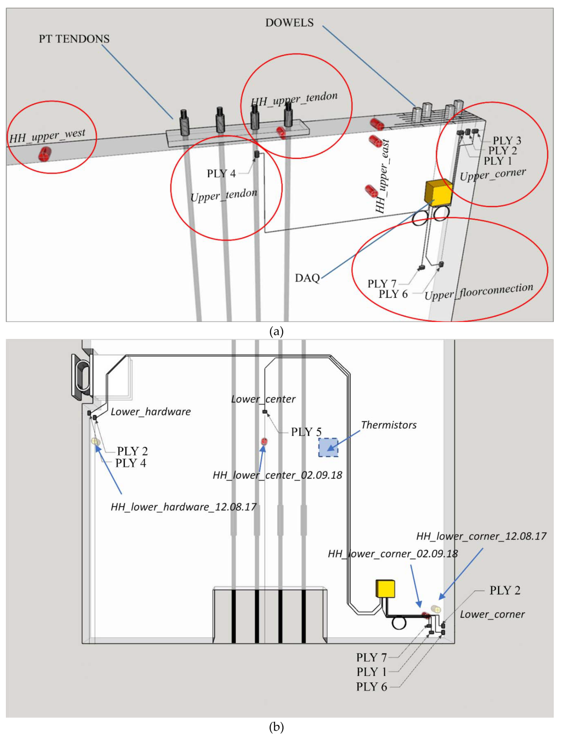
2.4. Hygrothermal Monitoring Locations
2.5. Post-Processing and Analysis of Moisture Content Data
3. Results
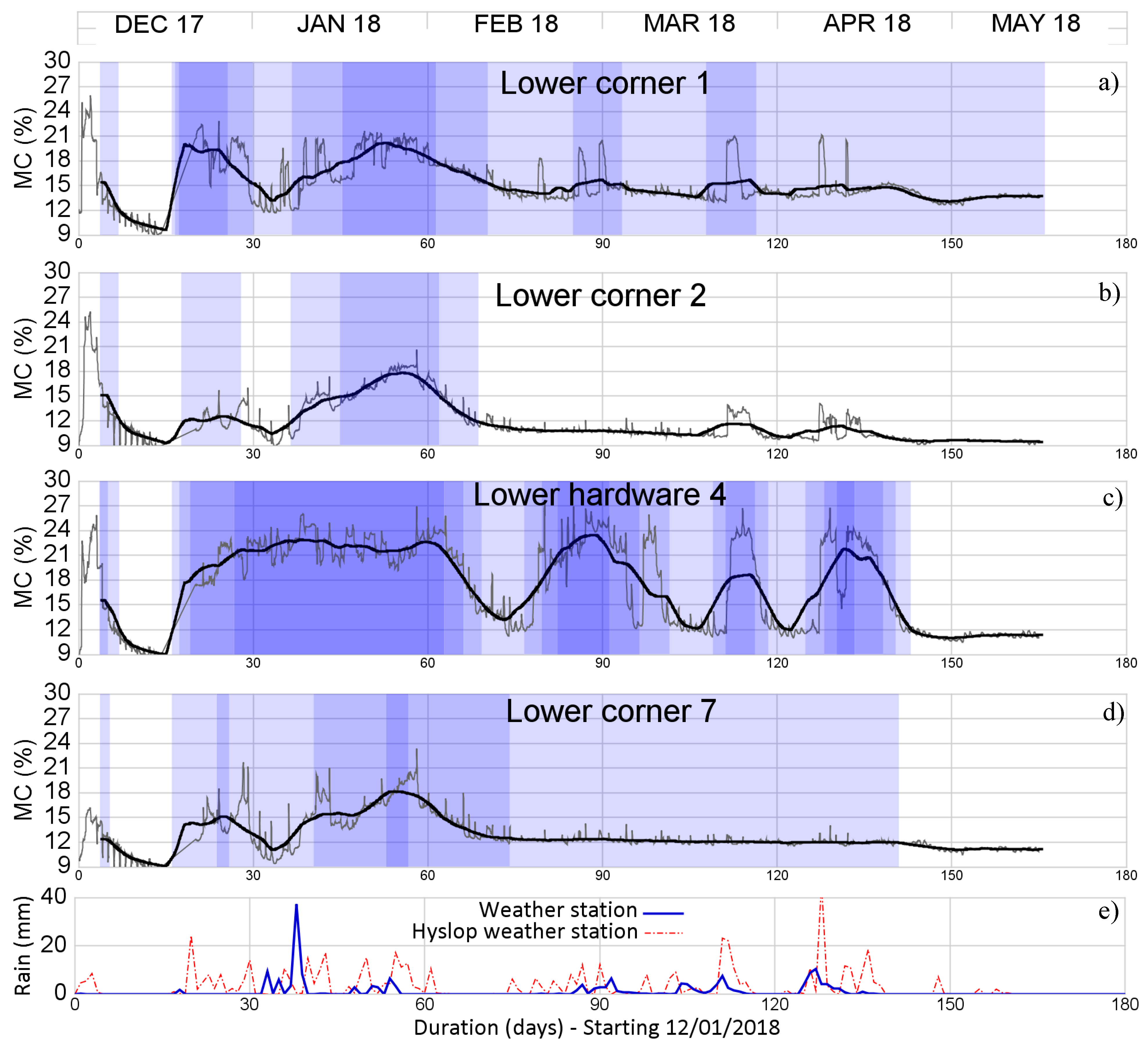
3.1. Weather
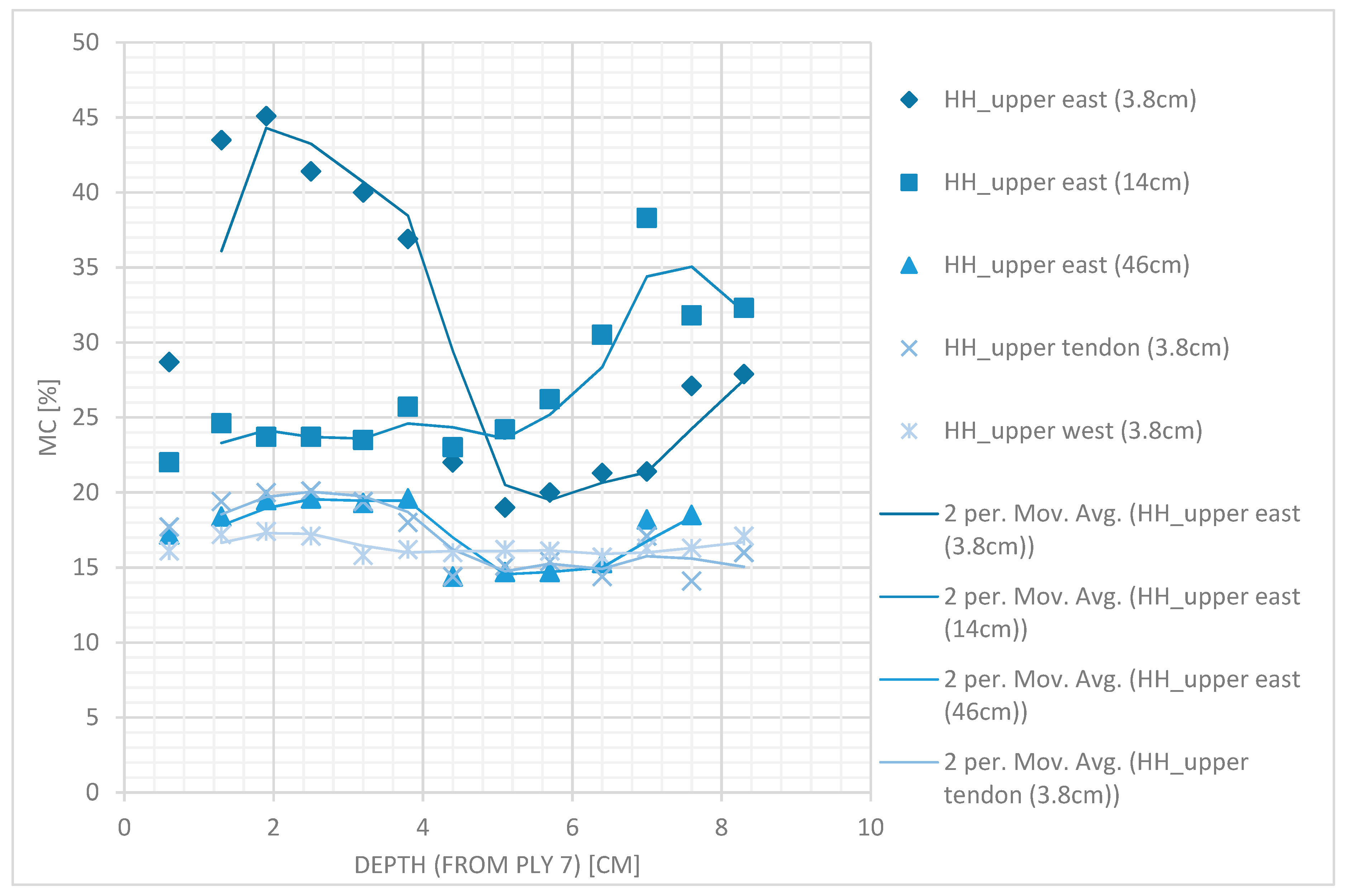
3.2. CLT Shear Wall Moisture Content
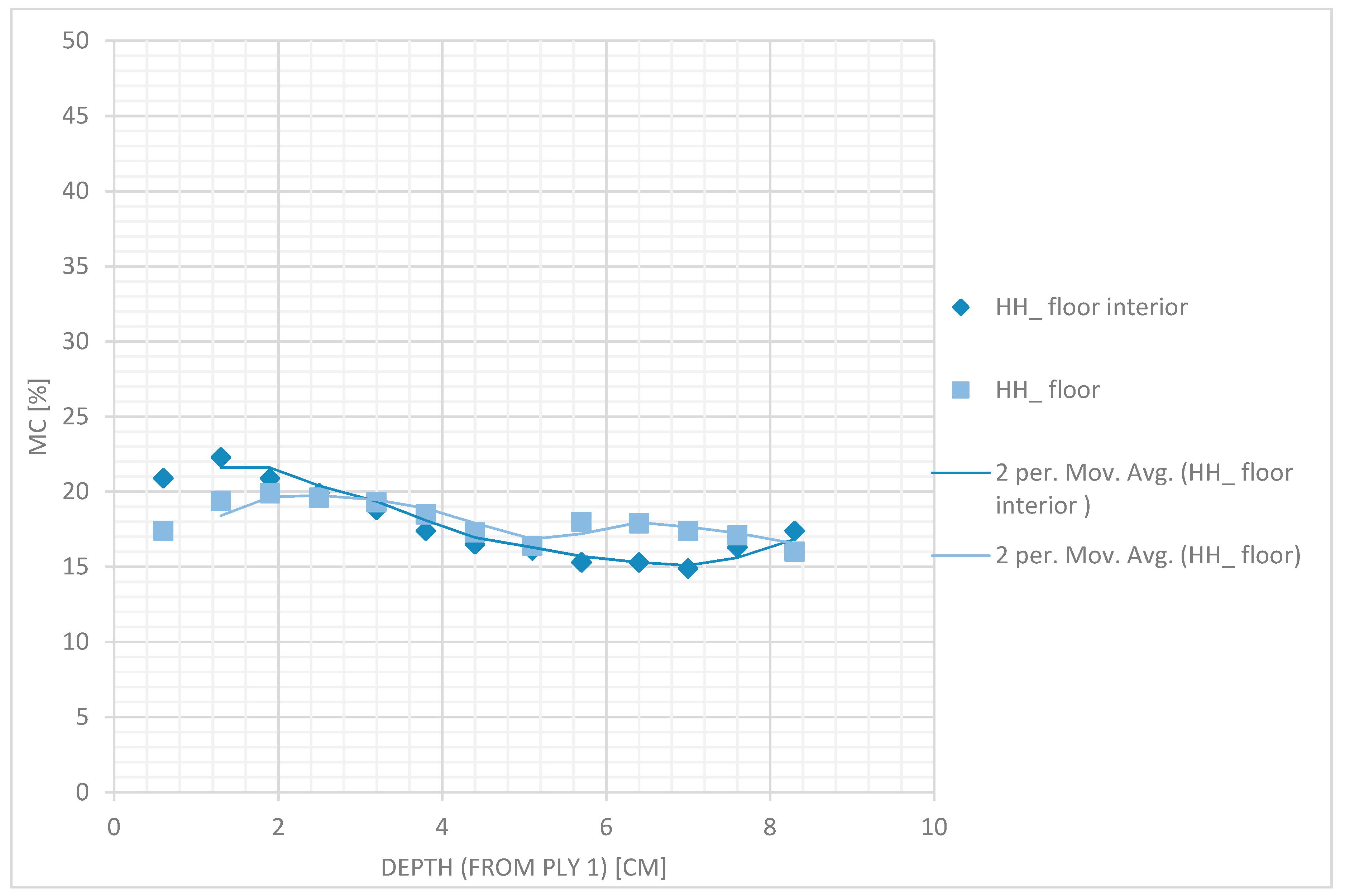
3.3. CLT floor Moisture Content
4. Discussion and Recommendations
4.1. Moisture Content in the CLT Shear Wall and Floor
4.2. Moisture Mitigation Considerations for Design and Construction
4.3. Data analysis and Hygrothermal Monitoring Considerations
5. Conclusions
Author Contributions
Funding
Acknowledgments
Conflicts of Interest
References
- Pei, S.; Rammer, D.; Popovski, M.; Williamson, T.; Line, P.; van de Lindt, J.W. An overview of CLT Research and Implementation in North America. In Proceedings of the WCTE 2016, Vienna, Austria, 22–25 August 2016. [Google Scholar]
- Gasparri, E.; Lucchini, A.; Mantegazza, G.; Mazzucchelli, E.S. Construction management for tall CLT buildings: From partial to total prefabrication of façade elements. Wood Mater. Sci. Eng. 2015, 10, 256–275. [Google Scholar] [CrossRef]
- Finnish Standards Association. Execution of Timber Structures, Rules for Load-Bearing Structures of Buildings; Finnish Standards Association, Confederation of Finnish Construction Industries RT: Helsinki, Finland, 2012. [Google Scholar]
- DIN 68800: 2012. Wood preservation—Part 2: Preventive Constructional Measures in Buildings; German Institute for Standardisation (Deutsches Institut für Normung), Beuth Verlad: Berlin, Germany, 2012. [Google Scholar]
- Wang, J. Guide for On-Site Moisture Management of Wood Construction; FPInnovations: Pointe-Claire, QC, Canada, 2016. [Google Scholar]
- Wang, J.W.; Stirling, R.; Morris, P.I.; Taylor, A.; Lloyd, J.; Kirker, G.; Lebow, S.; Mankowski, M.E.; Barnes, H.M.; Morrell, J.J. Durability of mass timber structures: A review of the biological risks. Wood Fiber Sci. 2018, 50, 110–127. [Google Scholar] [CrossRef]
- Viitanen, H. Factors Affecting the Development of Mould and Brown Rot Decay in Wooden Material and Wooden Structures. Effect of Humidity, Temperature and Exposure Time. Ph.D. Thesis, University of Uppsala, Uppsala, Sweden, 1996. [Google Scholar]
- Viitanen, H.; Vinha, J.; Salminen, K.; Ojanen, T.; Peuhkuri, R.; Paajanen, L. Moisture and bio-deterioration risk of building materials and structures. J. Build. Phys. 2010, 33, 201–224. [Google Scholar] [CrossRef]
- Isaksson, T.; Brischke, C.; Thelandersson, S. Development of decay performance models for outdoor timber structures. Mater. Struct. 2012, 46, 1209–1225. [Google Scholar] [CrossRef]
- Gülzow, A.; Richter, K.; Steiger, R. Influence of wood moisture content on bending and shear stiffness of cross laminated timber panels. Eur. J. Wood Wood Prod. 2011, 69, 193–197. [Google Scholar] [CrossRef]
- Schmidt, E.L.; Riggio, M.; Barbosa, A.R.; Mugabo, I. Environmental response of a CLT floor panel: Lessons for moisture management and monitoring of mass timber buildings. Build. Environ. 2019, 148, 609–622. [Google Scholar] [CrossRef]
- Schmidt, E.; Riggio, M.; Laleicke, P.F.; Barbosa, A.; van den Wymelenberg, K. How monitoring CLT buildings can remove market barriers and support designers in North America: An introduction to preliminary environmental studies. Rev. Port. Eng. Estrut. 2018, 7, 41–48. [Google Scholar]
- Nairn, J.A. Cross laminated timber properties including effects of non-glued edges and additional cracks. Eur. J. Wood Wood Prod. 2017, 75, 973–983. [Google Scholar] [CrossRef]
- Gamper, A.; Dietsch, P.; Merk, M.; Winter, S. Building Climate—Long-term measurements to determine the effect on the moisture gradient in large-span timber structures|Gebudeklima—Langzeitmessung zur Bestimmung der Auswirkungen auf Feuchtegradienten in Holzbauteilen. Bautechnik 2013, 90, 508–519. [Google Scholar] [CrossRef]
- Niklewski, J.; Isaksson, T.; Hansson, E.F.; Thelandersson, S. Moisture conditions of rain-exposed glue-laminated timber members: The effect of different detailing. Wood Mater. Sci. Eng. 2018, 13, 129–140. [Google Scholar] [CrossRef]
- Grossman, P.U.A. Requirements for a model that exhibits mechano-sorptive behavior. Wood Sci. Technol. 1976, 10, 163–168. [Google Scholar] [CrossRef]
- Holzer, S.M.; Loferski, J.R.; Dillard, D.A. A review of creep in wood: Concepts relevant to develop long-term behavior predictions for wood structures. Wood Fiber Sci. 1989, 21, 376–392. [Google Scholar]
- Granello, G.; Leyder, C.; Palermo, A.; Frangi, A.; Pampanin, S. Design Approach to Predict Post-Tensioning Losses in Post-Tensioned Timber Frames. J. Struct. Eng. 2018, 144, 04018115. [Google Scholar] [CrossRef]
- Nguyen, T.T.; Dao, T.N.; Aaleti, S.; Hossain, K.; Fridley, K.J. Numerical Model for Creep Behavior of Axially Loaded CLT Panels. J. Struct. Eng. 2019, 145, 04018224. [Google Scholar] [CrossRef]
- D’Ayala, D.; Aktas, Y.D. Moisture dynamics in the masonry fabric of historic buildings subjected to wind-driven rain and flooding. Build. Environ. 2016, 104, 208–220. [Google Scholar] [CrossRef] [Green Version]
- Dedesko, S.; Siegel, J.A. Moisture parameters and fungal communities associated with gypsum drywall in buildings. Microbiome 2015, 3, 71. [Google Scholar] [CrossRef] [PubMed]
- Bedon, C. Diagnostic analysis and dynamic identification of a glass suspension footbridge via on-site vibration experiments and FE numerical modelling. Compos. Struct. 2019, 216, 355–378. [Google Scholar] [CrossRef]
- Marques, L.F.R.L.; Lourenço, P.B.; de Roeck, G.; Campos-Costa, A.; Roque, J. Monitoring historical masonry structures with operational modal analysis: Two case studies. Mech. Syst. Signal Process. 2010, 24, 1291–1305. [Google Scholar] [Green Version]
- Tannert, T.; Berger, R.; Müller, A. Remote moisture monitoring of timber bridges: A case study. In Proceedings of the 5th International Conference on Structural Health Monitoring of Intelligent Infrastructure (SHMII-5) 2011, Cancun, Mexico, 11–15 December 2011; pp. 1–9. [Google Scholar]
- Björngrim, N.; Hagman, O.; Wang, X.A. Moisture content monitoring of a timber footbridge. BioResources 2016, 11, 3904–3913. [Google Scholar] [CrossRef]
- Koch, J.; Simon, A.; Arndt, R.W. Monitoring of Moisture Content of Protected Timber Bridges. In Proceedings of the WCTE 2016 World Conference Timber Engineering, Vienna, Austria, 22–25 August 2016. [Google Scholar]
- Sorin, E.; Lanata, F.; Boudaud, C. Behaviour of Timber Structures Under Variable Environment Through Long-Term Monitoring. In Proceedings of the WCTE 2016 World Conference Timber Engineering, Vienna, Austria, 22–25 August 2016. [Google Scholar]
- Jorge, L.; Dias, A.; Costa, R. Performance of X-Lam panels in a sports center with an indoor swimming-pool. J. Civ. Struct. Health Monit. 2015, 5, 129–139. [Google Scholar] [CrossRef]
- Leyder, A.F.C.; Chatzi, E. Structural health monitoring of an innovative timber structure. In Proceedings of the Second International Conference on Performance-Based and Life-Cycle Structural Engineering, Brisbane, Australia, 9–11 December 2015; Volume 6, No. 0974. pp. 102–108. [Google Scholar]
- Wang, J.; Karsh, E.; Finch, G.; Chen, M. Field Measurement of Vertical Movement and Roof Moisture Performance of the Wood Innovation and Design Centre. In Proceedings of the WCTE 2016 World Conference Timber Engineering, Vienna, Austria, 22–25 August 2016; No. Lvl. pp. 2–3. [Google Scholar]
- Mustapha, G.; Khondoker, K.; Higgins, J. Moisture Performance and Vertical Movement Monitoring of Pre-Fabricated Cross Laminate Timber—Featured Case Study: Ubc Tallwood House. In Proceedings of the 15th Canadian Conference on Building Science and Technology, Vancouver, BC, Canada, 6–8 November 2017; pp. 1–15. [Google Scholar]
- Mustapha, G.; Khondoker, K. Structural performance monitoring technology and data visualization tools and techniques—Featured case study: UBC Tallwood House. In Proceedings of the 1st International Conference on New Horizons in Green Civil Engineering, Victoria, BC, Canada, 25–27 April 2018. [Google Scholar]
- Kordziel, S. Study of Moisture Conditions in a Multi-Storey Mass Timber Building Through the Use of Sensors and WUFI Hygrothermal Modeling. Master’s Thesis, Colorado School of Mines, Golden, CO, USA, 2017. [Google Scholar]
- Zelinka, S.; Kordziel, S.; Pei, S.; Glass, S.V.; Tabares-Velasco, P.C. Moisture monitoring throughout the construction and occupancy of mass timber buildings. In Proceedings of the 1st International Conference on New Horizons in Green Civil Engineering, Victoria, BC, Canada, 25–27 April 2018; No. 3. pp. 25–28. [Google Scholar]
- Alsayegh, G.; Mukhopadhyaya, P.; Wang, J.; Zalok, E.; van Reenen, D. Preliminary Characterization of Physical Properties of Cross-Laminated-Timber (CLT) Panels for Hygrothermal Modelling. Adv. Civ. Eng. Mater. 2013, 2, 472–484. [Google Scholar] [CrossRef]
- Lepage, R. Moisture Response of Wall Assemblies of Cross-Laminated Timber Construction in Cold Canadian Climates. Master’s Thesis, University Waterloo, Waterloo, ON, Canada, 2012; p. 139. [Google Scholar]
- McClung, R.; Ge, H.; Straube, J.; Wang, J. Hygrothermal performance of cross-laminated timber wall assemblies with built-in moisture: Field measurements and simulations. Build. Environ. 2014, 71, 95–110. [Google Scholar] [CrossRef]
- Wang, J. Wetting and Drying Performance of Wood-Based Assemblies Related to On-Site Moisture Management. In Proceedings of the WCTE 2016 World Conference Timber Engineering, Vienna, Austria, 22–25 August 2016; No. 2. pp. 1–22. [Google Scholar]
- Lepage, R.; Finch, G. Moisture uptake testing for CLT floor panels in a tall wood building in Vancouver. In Proceedings of the 15th Canadian Conference on Building Science and Technology, Vancouver, BC, Canada, 6–8 November 2017; No. Mc. pp. 1–17. [Google Scholar]
- Sarti, F.; Palermo, A.; Pampanin, S. Simplified design procedures for post-tensioned seismic resistant timber walls. In Proceedings of the 15th WCEE, Lisbon, Portugal, 24–28 September 2012. [Google Scholar]
- van de Lindt, J.W.; Furley, J.; Aminic, M.O.; Pei, S.; Tamagnone, G.; Barbosa, A.R.; Rammer, D.; Line, P.; Fragiacomo, M.; Popovski, M. Experimental seismic behavior of a two-story CLT platform building. Eng. Struct. 2019, 183, 408–422. [Google Scholar] [CrossRef]
- Ortiz, E. Mass Plywood Panels: Designing with the Newest Mass Timber Structural Product. Available online: http://www.woodworks.org/wp-content/uploads/presentation_slides-ORTIZ-Mass-Plywood-Panels-WSF-180425.pdf (accessed on 24 September 2018).
- Riggio, M.; Alhariri, N.; Hansen, E. Paths of innovation and knowledge management in timber construction in North America: A focus on water control design strategies in CLT building enclosures. Archit. Eng. Des. Manag. 2019. [Google Scholar] [CrossRef]
- Dietsch, P.; Franke, S.; Franke, B.; Gamper, A.; Winter, S. Methods to determine wood moisture content and their applicability in monitoring concepts. J. Civ. Struct. Health Monit. 2014, 5, 115–127. [Google Scholar] [CrossRef]
- Hyslop Weather Station Archives. Available online: https://agsci.oregonstate.edu/corvallis-farm-unit/weather/weather-data (accessed on 5 June 2018).
- American National Standard /The Engineered Wood Association. Standard for Performance-Rated Cross-Laminated Timber; ANSI/APA PRG 320-2018; American Psychological Association: New York, NY, USA, 2018. [Google Scholar]
- Wengert, G.; Bois, P. Evaluation of electric moisture meters on kiln-dried lumber. For. Prod. J. 1997, 47, 60–62. [Google Scholar]
- Wilson, P. Accuracy of a capacitance-type and three resistance-type pin meters for measuring wood moisture content. For. Prod. J. 1999, 49, 29–32. [Google Scholar]
- James, W.L. Electric Moisture Meters for Wood; USDA-FS FPL-GTR-6; U.S. Department of Agriculture, Forest Service, Forest Products Laboratory: Madison, WI, USA, 1988.
- Riggio, M.; Anthony, R.W.; Augelli, F.; Kasal, B.; Lechner, T.; Muller, W.; Tannert, T. In Situ assessment of structural timber using non-destructive techniques. Mater. Struct. 2014, 47, 749–766. [Google Scholar] [CrossRef]
- Sandberg, K.; Pousette, A. Moisture Conditions in Coated Glulam Beams and Columns During Weathering. In Proceedings of the International Conference on Durability of Building Materials and Components, Porto, Portugal, 12–15 April 2011; pp. 1–8. [Google Scholar]
- Eugene: Monthly and Annual Climate. Administration, National Oceanic and Atmospheric. Available online: https://www.wrh.noaa.gov/pqr/eugclimate/pg67.pdf (accessed on 5 June 2018).
- Serrano, E. Limnologen—Experiences from an 8-Storey Timber Building Limnologen Potpourri—Praktische Erfahrungen von Immeubles en Bois de Huit Étages; Internationales Holzbau-Forum: Garmisch, Germany, 2009; pp. 1–12. [Google Scholar]
- Beebe, K.; Kam-Biron, M. Five Ds of Moisture Management: Deflection, Drainage, Drying, Distance, and Durable Materials. In Proceedings of the SEAC 2016, Montpellier, France, 21–22 October 2016. [Google Scholar]


© 2019 by the authors. Licensee MDPI, Basel, Switzerland. This article is an open access article distributed under the terms and conditions of the Creative Commons Attribution (CC BY) license (http://creativecommons.org/licenses/by/4.0/).
Share and Cite
Schmidt, E.; Riggio, M. Monitoring Moisture Performance of Cross-Laminated Timber Building Elements during Construction. Buildings 2019, 9, 144. https://doi.org/10.3390/buildings9060144
Schmidt E, Riggio M. Monitoring Moisture Performance of Cross-Laminated Timber Building Elements during Construction. Buildings. 2019; 9(6):144. https://doi.org/10.3390/buildings9060144
Chicago/Turabian StyleSchmidt, Evan, and Mariapaola Riggio. 2019. "Monitoring Moisture Performance of Cross-Laminated Timber Building Elements during Construction" Buildings 9, no. 6: 144. https://doi.org/10.3390/buildings9060144