Article

Advanced Seismic Retrofit of a Mixed R/C-Steel Structure

1
Department of Civil and Environmental Engineering, University of Florence, 50139 Florence, Italy
2
Polytechnic Department of Engineering and Architecture, University of Udine, 33100 Udine, Italy
*
Author to whom correspondence should be addressed.
Buildings 2019, 9(12), 241; https://doi.org/10.3390/buildings9120241
Submission received: 30 October 2019 / Revised: 19 November 2019 / Accepted: 26 November 2019 / Published: 29 November 2019

Abstract

:
A study concerning the performance assessment and enhanced retrofit of public buildings originally designed without any anti-seismic provisions is presented herein. A representative structure belonging to this class was demonstratively examined, i.e., a school built in Italy in the early 1970s, before a coordinate national Seismic Standard was issued. The building is characterized by a mixed reinforced concrete (ground storey)–steel (first and second storey) frame skeleton. An extensive on-site experimental investigation was developed in the first step of the study, which helped identify the mechanical characteristics of the constituting materials, and re-draw the main structural details. Based on these data, and relevant updates of the finite element model of the structure, the seismic assessment analyses carried out in current conditions highlighted several performance deficiencies, in both the reinforced concrete and steel members. An advanced seismic retrofit hypothesis of the building was then designed, consisting of the installation of a set of dissipative braces incorporating fluid viscous dampers as protective devices. This solution makes it possible to attain an elastic structural response up to the maximum considered normative earthquake level, while at the same time causing more limited architectural intrusion and lower costs as compared to conventional rehabilitation strategies.

1. Introduction

In spite of their modern conception as compared to traditional masonry buildings, reinforced concrete (R/C) and steel frame structures designed in Italy before the issue of a coordinate national Seismic Standard [1,2] have methodically shown poor response capacities to earthquakes, even of low-to-moderate intensity [3], in the last few decades. This has caused government authorities to grant financial incentives for the reduction in the seismic vulnerability of private buildings with a frame structure [4]. At the same time, several regional and municipal authorities have promoted performance assessment campaigns and systematic retrofit interventions of public buildings with R/C and steel structure, with special care to schools. Indeed, the latter have always been among the most severely damaged stocks of public buildings with frame structure, as recently confirmed also by the 2016 central Italy earthquake [5].
The seismic retrofit strategies adopted for schools are increasingly oriented to the use of supplemental energy dissipation systems, in view of their high performance capacities and low architectural intrusion characteristics. Several types of dissipaters may be adopted, belonging to the classes of metallic yielding, friction, visco-elastic, and fluid viscous dampers. Among these four basic categories, fluid viscous devices are currently the most widely utilized due to their combined high performance/undamaging response capacities, as also witnessed by the numerous latest research and design achievements in this field [6,7,8,9,10,11,12,13,14,15,16,17,18,19,20,21,22,23,24,25,26,27].
The study presented in this article belongs to this line of activity. By developing and expanding a preliminary investigation recently carried out by the authors [4], attention is focused on a representative building, i.e., a school built in Florence in the early 1970s. The frame structure is of mixed type, constituted by a reinforced concrete (R/C) frame skeleton on the ground storey, and reticular steel beams and columns on the first and second storeys. A detailed seismic assessment analysis carried out in current conditions showed noticeably unsafe stress states in the R/C and steel members, starting from the normative basic design earthquake (BDE) level.
This prompted the proposition of a retrofit solution for the building, consisting of the installation of a special dissipative bracing system incorporating fluid viscous (FV) devices. So far, this technology, conceived, implemented, and experimentally tested by the first and fourth author [28,29], has been developed for application to various types of R/C [30,31,32,33] and steel [34,35] structures, and is studied for the first time for mixed R/C-steel buildings herein. The design objective of the intervention is represented by the attainment of an undamaged response of the structure, as well as of the non-structural components, up to the maximum considered earthquake (MCE) normative level.
Details on the geometrical and structural characteristics of the building, as derived from a careful preliminary investigation campaign, as well as of the performance assessment analyses, the retrofit hypothesis, and its design process, are offered in the next sections.

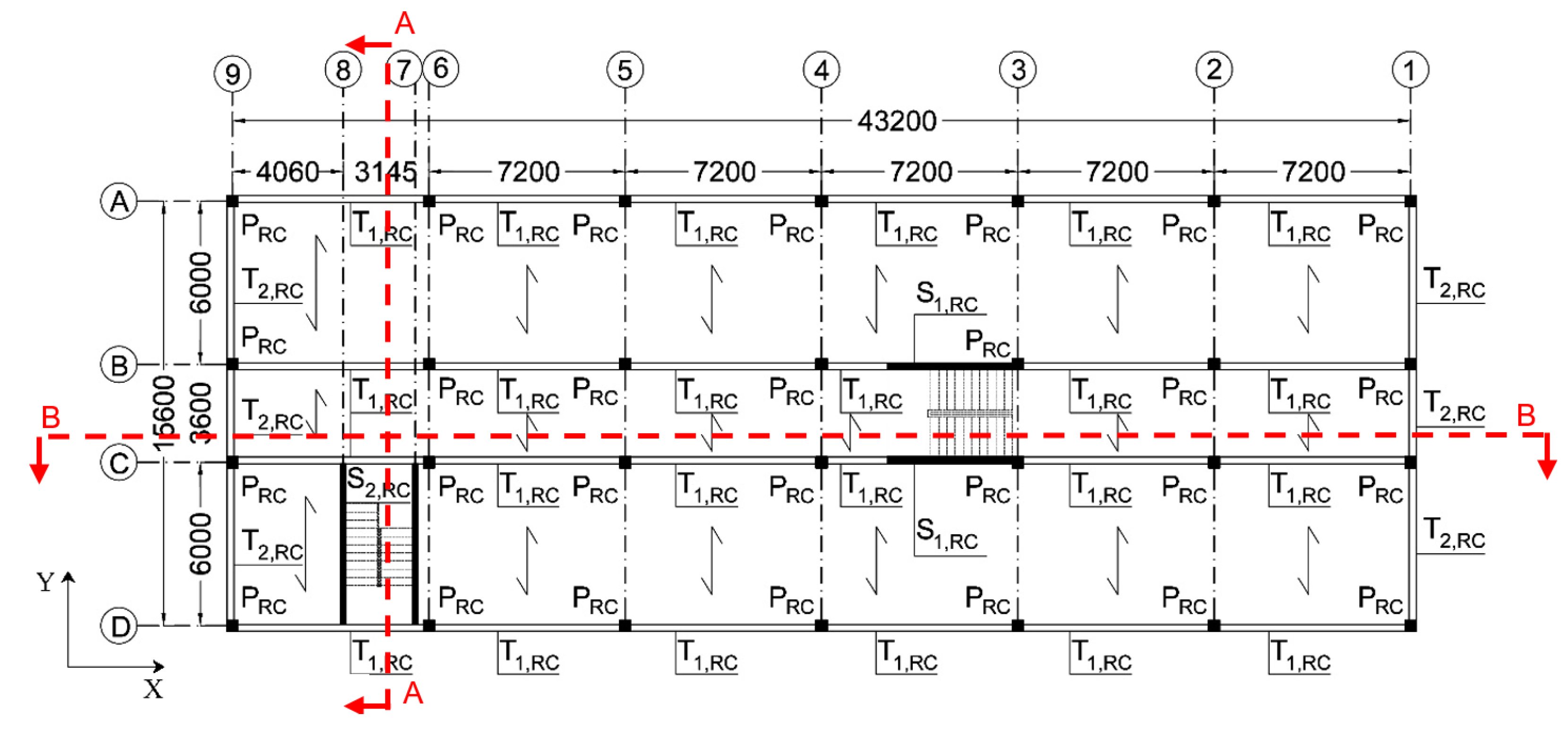
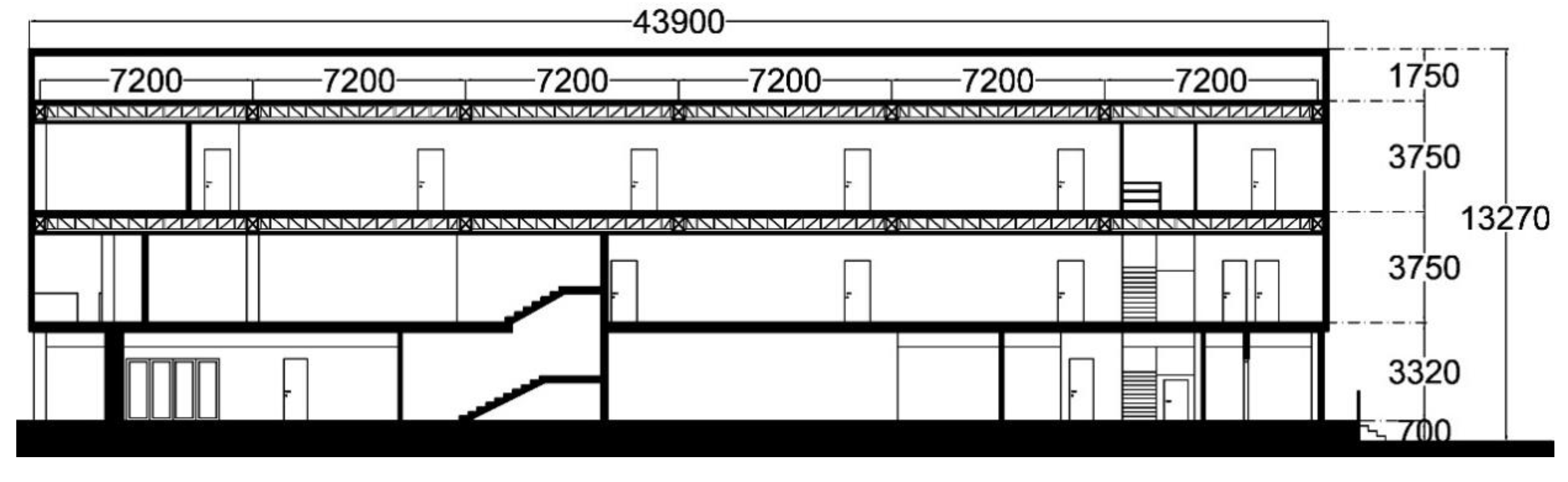
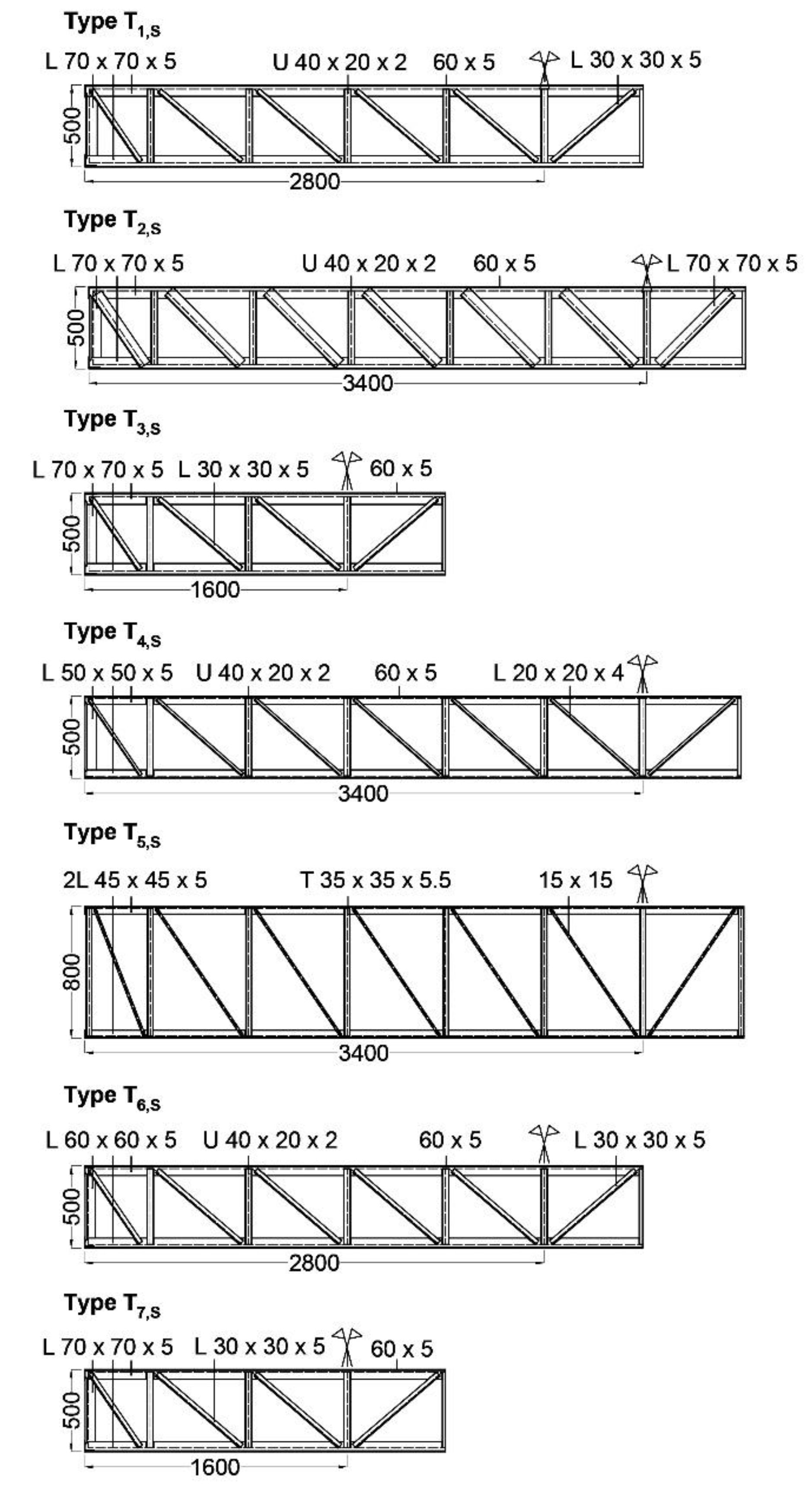
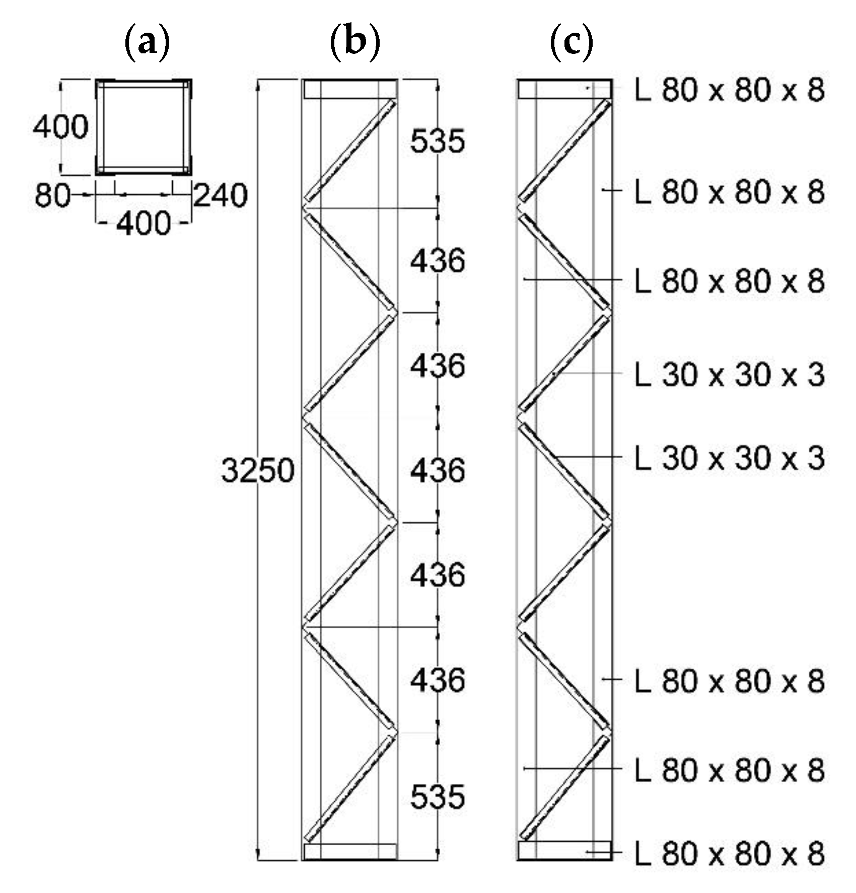
2. Case Study School Building

Figure 1 shows the first-floor plan, with maximum external dimensions of (43.9 × 16.3) m2. The total area of the three floors is about 2100 m2 and the total volume of the building is 8300 m3. As highlighted by the cross sections in Figure 2 and Figure 3, storey heights are equal to 3.30 m (ground storey) and 3.75 m (upper storeys). According to the nomenclature in Figure 1, and as illustrated in Figure 4, R/C beams T1,RC have cross section of (250 × 740) mm2 and are reinforced by ϕ12 circular bars and square bars (indicated by a square symbol in the drawing) with sides of 10 mm, and 8 mm square stirrups; R/C beams T2,RC have section of (250 × 740) mm2, with 18 mm square bars and 8.5 mm square stirrups. R/C columns have section of (400 × 400) mm2, with 18 mm square bars and 8 mm square stirrups; R/C walls S1,RC have section of (5900 × 200) mm2 with ϕ12 vertical bars and ϕ8 transversal bars. The floors are of R/C “Predalles” type on the ground floor, and constituted by prefab joists on the upper floors. The foundation is made of grade beams at the base of the R/C columns and two slabs situated below the stairwell R/C walls. The second and third floor plans are shown in Figure 5 and Figure 6. The seven different types of reticular steel beams numbered in these drawings are displayed in Figure 7. A single type of reticular steel column is present, detailed in Figure 8. The roof is made of light prefab R/C purlins supported by Mohnié-type steel trusses.

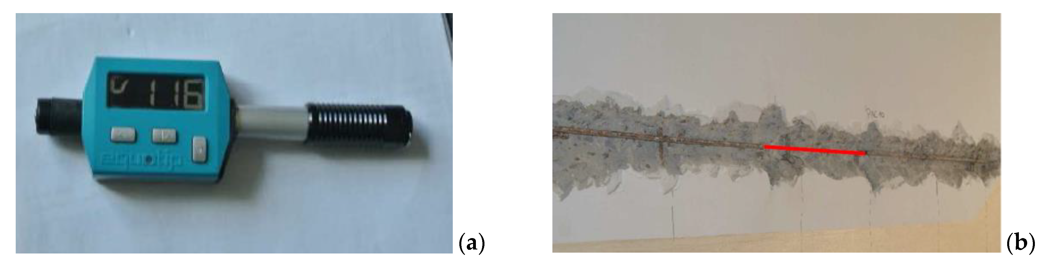
3. On-Site Testing Campaign

An extensive on-site testing campaign was carried out on the building to identify the mechanical characteristics of the constituting materials and re-draw the main structural details, starting from the original design documentation. The on-site testing programme consisted of: core drillings, pacometer tests, and extraction of steel reinforcement samples on the ground storey R/C members; and micro-durometer tests for the steel members, plus magnetic particle inspection tests on their welded joints.
The plans in Figure 9 illustrate the type and positions of the on-site characterization tests carried out on the three storeys.
The following nomenclature is used in Figure 9 to denote the testing activities: C—core drillings, developed to determine the compression strength of concrete by laboratory tests on the samples obtained; Pac—pacometer tests, to measure the cover thickness, and detect the rebar positions and spacing, as well as to estimate their diameter (circular bars) or side (square bars); S—drilled holes, to check the results of the pacometer tests by a direct visualization of little internal portions of members; P—extraction of steel bars, to determine the reinforcing steel tensile strength by laboratory tests on the samples obtained; D—micro-durometer tests, to derive an indirect estimate of the tensile strength of the steel bars by means of the Vickers’ hardness parameter; CS—magnetic particle inspection tests on welded joints, to detect their surface and shallow subsurface discontinuities and cracks, aimed to evaluating their residual strength.
Some images taken during the development of the testing campaign are collected in Figure 10 and Figure 11. In particular, the pictures show: the placement of the core drill on a column of the ground storey (Figure 10a) and an example of extracted concrete core (Figure 10b); a pacometer used in the tests (Figure 10c) and the resulting positions of vertical bars and stirrups traced out on a column face (Figure 10d); a micro-durometer used in the tests (Figure 11a); and a steel bar before the cut of a portion of it, highlighted in red, after the concrete cover removal (Figure 11b).
The following main mechanical properties of the constituting materials resulted from the characterization tests: mean cubic compressive strength of concrete equal to 21.5 N/mm2; yield stress of reinforcing steel equal to 421 MPa; yield stress of the steel members equal to 235 MPa.
The information gained from the testing campaign made it possible to reach the highest “knowledge level” (named LC3) established by the current Italian Technical Standards [36,37] in the structural assessment analysis of existing buildings. The corresponding value of the “confidence factor”, FC, is equal to 1.

4. Assessment Analysis in Current Conditions

4.1. Modal Analysis

The finite element model of the structure was generated by the SAP2000NL calculus program [38], using frame type elements for the R/C columns and beams and the steel reticular members, and shell elements for the R/C walls. Figure 12 offers a global view of the model, which represents an upgraded and much more detailed version of the model used for the preliminary investigation carried out on the building [3], as mentioned in the Introduction, and a zoomed-in view of a steel beam-to-column joint. The steel trusses of the roof were modelled and checked separately, so as to avoid burdening the computational effort of the solution process. The resultant forces at truss ends derived from their separate analysis were applied to the top sections of relevant supporting perimeter columns in the model of Figure 12. Moreover, the prefab cladding panels of the façades, having simply pinned connections to the beams, were considered as equivalent concentrated loads at their ends.
The results of the modal analysis show four main vibration modes. The first one is mixed translational along Y–rotational around Z, with a period of 0.61 s, and effective modal mass (EMM) equal to 48.5% of the total seismic mass in Y and 35.7% around Z; the second is purely translational along X, with a period of 0.29 s and EMM of 31.2%; the third is purely rotational around Z, with a period of 0.24 s and EMM of 14.9%; and the fourth is purely translational along Y, with a period of 0.22 s and EMM of 11.9%. A total of 50 modes was needed to activate 100% of the total seismic mass along X and Y and around Z, due to the complexity of the model, which produced several secondary modes associated to the local deformation of single elements and/or limited portions of the structure, rather than to its overall response.

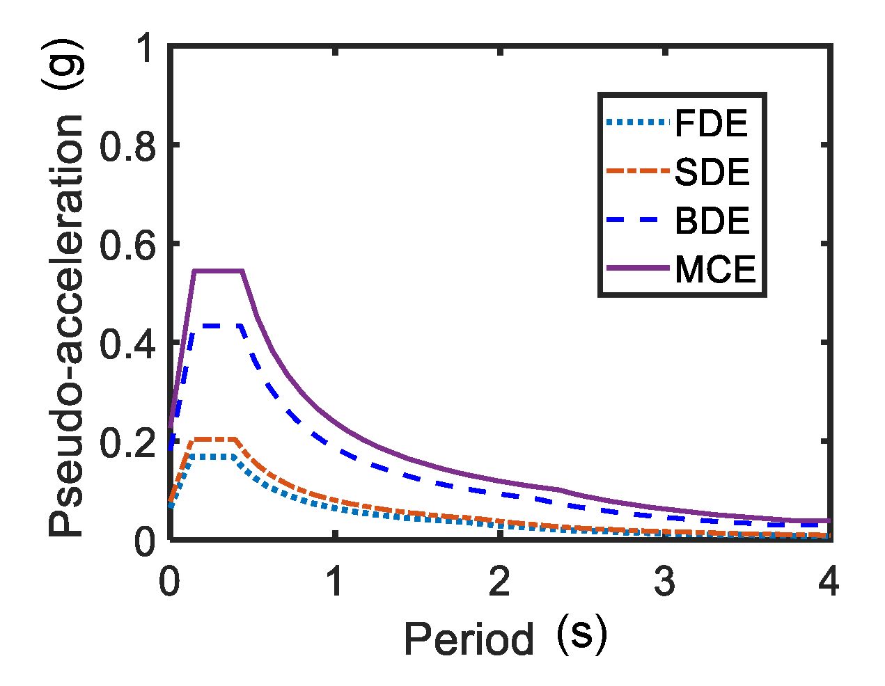
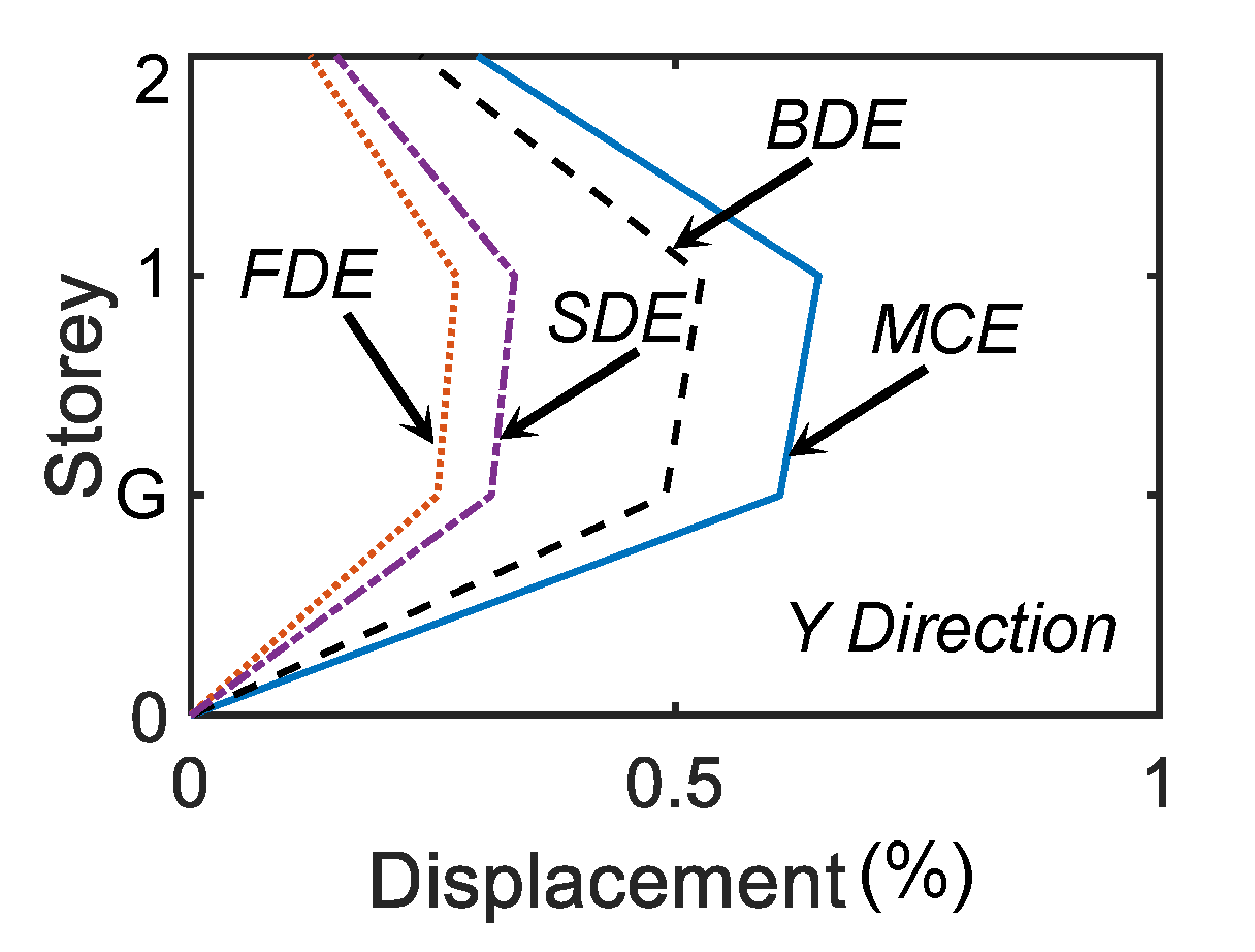
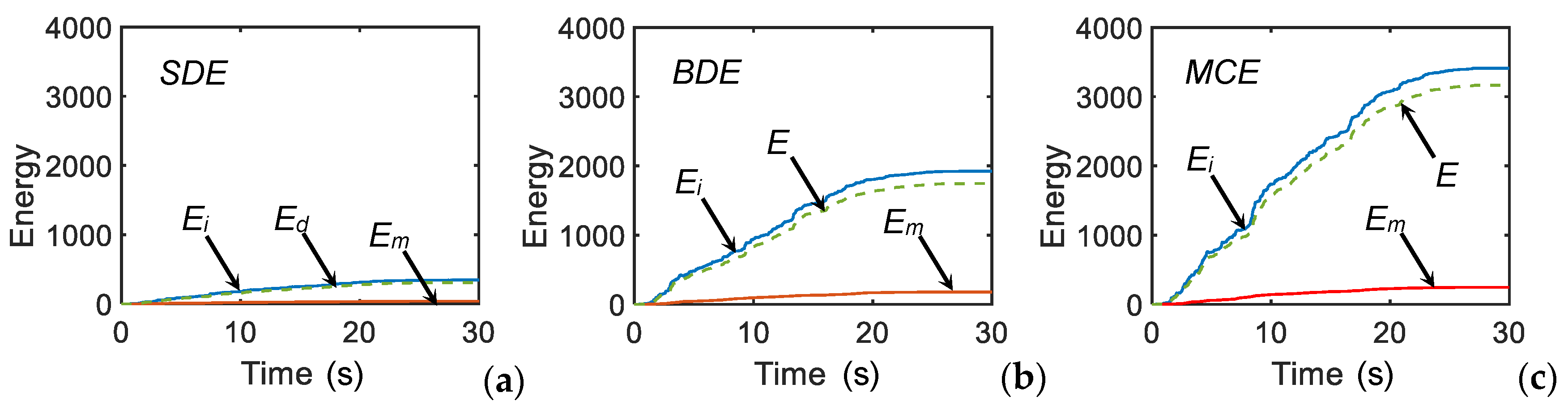
4.2. Time-History Verification and Performance Assessment Analysis

The performance evaluation analysis was carried out for the four reference seismic levels fixed in the Italian Standards [36], that is, frequent design earthquake (FDE, with 81% probability of being exceeded over the reference time period VR); serviceability design earthquake (SDE, with 50%/VR probability); basic design earthquake (BDE, with 10%/VR probability); and maximum considered earthquake (MCE, with 5%/VR probability). The VR period was fixed at 75 years, which was obtained by multiplying the nominal structural life VN of 50 years by a coefficient of use Cu equal to 1.5, imposed to the design of school buildings or the assessment analysis of existing ones. By referring to topographic category T1 (flat surface), and B-type soil, the resulting peak ground accelerations for the four seismic levels for the city of Florence are as follows: 0.065 g (FDE), 0.078 g (SDE), 0.181 g (BDE), and 0.227 g (MCE). For the development of the time-history analyses, two families of seven accelerograms were generated by SIMQKE-II software [39] from the pseudo-acceleration elastic response spectra for Florence, plotted in Figure 13. In each time-history analysis the accelerograms were applied in groups of two simultaneous components, with the first one selected from the first generated family of seven motions, and the second one selected from the second family.
The results of the analyses were assessed in terms of maximum inter-storey drift ratio (i.e., the ratio of the maximum inter-storey drift to the inter-storey height), IDmax, and maximum stress states in the structural members.
The IDmax envelopes obtained for the four seismic levels, plotted in Figure 14 for the weakest direction Y, were below the immediate occupancy level-related threshold IDIO, equal to 0.5% [36,37], for the FDE and SDE limit states. IDIO was slightly exceeded at the BDE, where IDmax reached 0.54% on the first storey, and more appreciably at the MCE, with a IDmax value of 0.66% on the same storey.
The stress states-based performance evaluation highlighted unsafe response, starting from the BDE, both of R/C and steel columns. For the former, the bending moment-axial force checks were not met in several alignments, with maximum non-safety factors of 2.53 at the MCE, as discussed in the next section. Concerning the steel members, the axial force buckling (i.e., Eulerian stability-related) limits computed for the vertical and diagonal L-type profiles were exceeded in several elements. This is symbolically represented in Figure 15, by way of example, for a perimeter column, whose portion containing the profiles in unsafe conditions is highlighted in red. The most stressed elements were affected by buckling-related unsafe factors at the MCE equal to 1.6—vertical profiles—and 2.22—diagonal profiles.
By summarizing the results of the assessment study, the combined good performance in terms of drifts and poor performance in terms of stress states emerging from the time-history analysis prompts the adoption of a retrofit strategy with limited stiffening/high damping characteristics, as discussed in the following section.

5. Retrofit Solution

The intervention hypothesis consists of the installation of a dissipative bracing system incorporating FV spring-dampers along both directions in the plan, and namely, in the following vertical alignments (according to the nomenclature in Figure 1, Figure 5 and Figure 6): A9-A6, A5-A4, A4-A3, A2-A1, D9-D6, D5-D4, D4-D3, D2-D1 in X, and 9A-9B, 9B-9C, 9C-9D, 1A-1B, 1B-1C, 1C-1D in Y, on the ground storey; A9-A6, A5-A4, A4-A3, A2-A1, D9-D6, D5-D4, D4-D3, D2-D1 in X, and 9A-9B, 9C-9D, 1A-1B, 1C-1D in Y, on the first and second storeys. A view of the finite element model including the protection system is shown in Figure 16.

5.1. Mechanical Characteristics of the FV Dampers

According to the general layout of the protective system [28], conceived with the aim of adjusting to various types of structures and infrastructures, the FV devices were installed in pairs at the tip of the supporting diagonal trusses, with inverted V-shaped layout. This is illustrated for the case study building in the drawing on the right of Figure 16, which also shows the trapezoidal steel plates welded to the upper reticular beam, to safely absorb the local stress states induced by the action of the dampers.
Unlike other classes of dissipaters, FV devices provide a very high damping action with small stiffening effects, which represents an effective property for structures like the one examined here, as observed above.
The mechanical behaviour of the FV spring-dampers is characterized by the following damping and elastic response force components [40]:
F d = c · s g n [ x ˙ ( t ) ] | x ˙ ( t ) | γ ,
F n e ( t ) = k 2 x ( t ) + ( k 1 k 2 ) [ 1 + | k 1 ( t ) F 0 | 5 ] 1 5 x ( t ) ,
where t = time variable; c = damping coefficient; sgn(·) = signum function; x ˙ (t) = velocity; |·| = absolute value; = fractional exponent, ranging from 0.1 to 0.2; F0 = static pre-load; k1, k2 = stiffness of the response branches situated below and beyond F0; and x(t) = displacement.

5.2. Sizing Design Procedure of FV Dampers and Performance Verification Analysis in Retrofitted Conditions

The FV dissipaters were sized by applying the procedure proposed in [41]. Based on its open formulation, it can be easily extended to reticular steel elements, like the ones constituting the skeleton of the two upper storeys of the case study building, which are mainly affected by low axial force buckling limits of the constituting profiles.
The procedure starts by assuming prefixed reduction factors, αs, of the most critical response parameters in current conditions, which are set as equal to the maximum non-safety factors determined by the preliminary assessment analysis. Simple formulas relating the αs factors to the equivalent viscous damping ratio of the dampers, ξeq, allow the calculation of the ξeq values that guarantee the achievement of the target αs values. Finally, the energy dissipation capacity of the devices is deduced from ξeq, finalizing their sizing process.
What makes the application of the procedure to the examined structure peculiar is that, as observed above, in this case αs must be computed by considering also the possible axial instability of the profiles composing the reticular steel members. Hence, said M j a the maximum moment calculated from the analysis in current conditions for the most stressed R/C member and N j a the maximum axial force in a reticular steel member profile belonging to the j-th storey, and M R ,     N c r   the corresponding limit resistance moment and axial force buckling limit, the αs ratio is given by:
α s = M j a M R   or   α s = N j a N c r .
By introducing these relations in the ξ e q equation formulated in [41]:
ξ e q = 2 ( α s 1 ) π · α s ,
and substituting ξ e q in the dissipated energy expression [41]:
E D = 2 π α s F e ξ e q I D e ,
where Fe = elastic storey shear limit, and IDe = elastic inter-storey drift limit, the energy dissipation capacity of the FV dampers, ED, can be estimated, and then the devices with the nearest mechanical characteristics, can be selected, as identified from the manufacturer’s catalogue [42].
The assessment analysis in the current conditions highlighted that the most stressed columns of all storeys were 1B for the flexural response around Y, and 1C around X. In the theoretical hypothesis of indefinitely elastic behaviour of the material, for the MCE-scaled seismic action the M j a value on the ground storey, M G S a , was equal to 68 kNm in column 1B around Y ( M G S , Y a ), and 290.9 kNm in column 1C around X ( M G S , X a ) .   The corresponding ultimate values intercepted on the boundary of the biaxial moment safe domain of columns were as follows: M G S , Y R = 26.9 kNm (computed for the concurrent axial force NS = 390.2 kN), and M G S , X R = 128.2 kNm (NS = 403.6 kN). The most critical conditions on the first storey were checked in the diagonal trusses of column 1C, with maximum calculated axial force values N I S , Y a = 73.9 kN along Y and N I S , X a = 51.6 kN along X, and a corresponding axial force buckling limit, N d i a g c r , of 33.3 kN. Concerning the second storey, the most demanding axial force conditions were surveyed in the vertical profiles of column 1C, equal to N I I S , X a = 450.6 kN in X and N I I S , Y a = 399.1 kN in Y, in comparison to the axial force buckling limit N v e r t c r = 279.6   kN.
Based on the results of the analysis, the following reduction factors αs were computed for the three storeys and the two directions in the plan: αs,GSM,X = 2.53, αs,GSM,Y = 2.26 (ground storey); αs,ISN,X = 2.22, αs,ISM,Y = 1.55 (first storey); and αs,IISN,X = 1.6, αs,IISN,Y = 1.42 (second storey). The corresponding equivalent viscous damping ratios of the sets of FV spring-dampers to be installed on the three levels, calculated by means of Equation (4), were: ξeq,GS,X = 0.38, ξeq,GS,Y = 0.35, ξeq,IS,X = 0.35, ξeq,IS,Y = 0.23, ξeq,IIS,X = 0.24, and ξeq,IIS,Y = 0.3. The ED energy dissipation capacities of the spring-dampers were consequently computed by Equation (5), for the following values of the elastic shear limit of the j-th storey (given by the sum of the elastic limit shear forces of all columns belonging to the same storey) in X, Fej,X, and Y, Fej,Y: FeGS,Y = 3502 kN, FeGS,Y = 4098 kN, FeIS,X = FeIS,Y = FeIIS,X = FeIIS,Y = 4288 kN, and the corresponding elastic drift limits: IDeSG = 16 mm; IDeSI = IDeSII = 19 mm. Therefore, the following tentative ED values were estimated: EDGS,X = 395 kJ, EDGS,Y = 278 kJ, EDIS,X = 397 kJ, EDIS,Y = 182 kJ, EDIIS,X = 409 kJ, EDIIS,Y = 196 kJ.
The design of the spring-dampers was finalized by referring to the total dissipated energy in the two directions: EDtot,X = EDGS,X + EDIS,X + EDIIS,X = 1201 kJ, EDtot,Y = EDGS,Y + EDIS,Y + EDIIS,Y = 656 kJ. By dividing these values by the number of devices placed in X and Y, equal to 48 and 28, respectively, the maximum energy dissipation capacity EDdev,X,max , EDdev,Y,max that should be assigned to each one of them to reach the target performance at the MCE was as follows: EDdev,X,max = 24.8 kJ, EDdev,Y,max = 23 kJ. Assuming these two similar energy values as sizing limits, the spring-damper type with the nearest nominal energy dissipation capacity En to EDdev,X,dmax, EDdev,Y,dmax has the following mechanical properties, as drawn from the manufacturer’s catalogue [42]: En = 24 kJ; stroke smax = ±50 mm; damping coefficient c = 38 kN(s/mm)γ, with γ = 0.15; F0 = 60 kN; and k2 = 1.55 kN/mm.
Based on this assumption, a final seismic performance verification analysis in retrofitted conditions was carried out, which highlighted the attainment of the planned performance improvements. In terms of drifts, this was demonstrated by the maximum envelopes in Figure 17, reduced far below the IDIO limit of 0.5% for all storeys. Moreover, it can be noted that all drifts also fell below the limit assumed by Italian Standards for the Operational performance level, IDOP, equal to 0.33%, which guarantees a completely undamaged response of non-structural elements, in addition to structural members, up to the MCE.
Concerning the stress states-related response, the maximum moments and axial forces in the current state, mentioned above and recalled here for direct comparison, were reduced to the following values in retrofitted conditions, identified by the additional lower index r:   M r G S , Y a = 40 kNm (against M G S , Y a = 68 kNm) in column 1B around Y; M r G S , X a = 91.9 kNm (against M G S , X a = 290.9 kNm) in column 1C around X; N r I S , X a = 28.2 kN (against N I S , X a = 73.9 kN) in the diagonal profiles of column 1C on the first storey, and N r I I S , X a = 268.3 kN (against N I I S , X a = 450.6 kN) in the vertical profiles of column 1C on the second storey. All these values are below the corresponding strength or buckling limits indicated above.
By way of example of the response in terms of energy balance, the input (Ei), FV-dissipated (Ed) and modal (Em) energy time-histories deriving from the analyses carried out with the most severe SDE, BDE, and MCE-scaled input accelerograms are plotted in Figure 18. These curves assess that the FV spring-dampers were already activated at the SDE, and their contribution ranged from 90% (SDE) to 85% (MDE) of the total input energy.
Thanks to the combined low stiffening/high damping capacity of the dissipative bracing system, the stress states in retrofitted conditions are safely absorbed in the foundation members up to the MCE, and thus no strengthening intervention is required on them.
The estimated cost of the structural works amounts to about 250 Euros/m2, i.e., about the same as that computed for buildings with different structural characteristics examined in previous steps of this research [30,31,33,35]. At the same time, the cost is approximately 30% lower than the typical cost of a conventional rehabilitation intervention carried out on public buildings with R/C or steel frame skeleton, located in a site of comparable seismicity to the case study one. The duration of the structural works is about nine months, which translates to one school-year of interruption of usage only, including any working uncertainties.

6. Conclusions

The study carried out on the selected school building, representative of the wide Italian stock of public edifices designed before a coordinate national Seismic Standard was issued, confirmed the high seismic vulnerability of this class of structures. At the same time, the peculiar characteristics of the building, represented by the uncommon presence of a mixed R/C-steel skeleton, determines a relatively high lateral stiffness of the structural system.
This prompted the adoption of a retrofit strategy with limited stiffening/high damping properties, that is, a dissipative bracing technology incorporating FV spring-dampers as protective devices. This technology, conceived and implemented in previous studies for installation in various types of R/C or steel structures and infrastructures, was for the first time applied to a case study with this special mixed structural configuration.
The design method adopted for sizing the spring-dampers, originally devised for frame structures with poor shear and/or bending moment strength of columns and beams, was extended to the reticular steel elements constituting the first and second storey skeleton with no need for conceptual or operational modification.
The results of the analyses in the current conditions highlighted maximum non-safety factors, set as equal to the response reduction factors imposed in the design procedure, ranging from about 2.5, for the ground storey R/C columns, to 2.2 and 1.6 for the first and second storey reticular steel columns, respectively.
The retrofit intervention makes it possible to reach an elastic and safe response of all structural members, as well as reduce the inter-storey drifts below the operational performance level-related limit, at the MCE, with lower costs, structural works duration, and architectural intrusion, as compared to conventional seismic rehabilitation alternatives.
This study also proves the effectiveness of the sizing method of the FV spring-dampers in directing the design process towards an optimal cost-to-benefit final solution.

Author Contributions

Conceptualization, G.T. and S.S.; methodology, G.T. and S.S.; software, C.B. and I.C.; validation, C.B., I.C., G.T. and S.S.; formal analysis, C.B.; investigation, G.T., C.B. and I.C.; resources, P.S.; data curation, G.T. and P.S.; writing—original draft preparation, S.S.; writing—review and editing, S.S.; funding acquisition, P.S.

Funding

Financial support from ReLUIS-DPC Project 2019-2021 (Work Package 15: Normative Contributions for Isolation Project 9–protocol nr. 60–05/02/2019–grant nr. 1100004434, 10.13039/50) is gratefully acknowledged.

Conflicts of Interest

The authors declare no conflict of interest.

References

  1. Ministry of Public Works. Technical Provisions for Constructions, with Special Prescriptions for Seismic Zones; Law no. 64, 2 February 1974. Ordinary supplement to G.U. no. 76, 21 March 1974; Ministry of Public Works: Rome, Italy, 1974. (In Italian)
  2. Ministry of Public Works. Approval of Technical Standards for Constructions in Seismic Zones; Ministerial Decree, 3 March 1975. Ordinary supplement to G.U. no. 93, 8 April 1975; Ministry of Public Works: Rome, Italy, 1975. (In Italian)
  3. Terenzi, G.; Bazzani, C.; Costoli, I.; Sorace, S.; Spinelli, P. Seismic assessment and retrofit design of a school building in Florence. In IOP Conference Series: Materials Science and Engineering, Proceedings of the 4th World Multidisciplinary Civil Engineering-Architecture-Urban Planning Symposium, WMCAUS 2019, Prague, Czech Republic, 17–21 June 2019; IOP Publishing: Bristol, UK, 2019; Volume 603, Paper No. 032003. [Google Scholar]
  4. Ministry of Infrastructure and Transport. Guidelines for the Classification of Seismic Risk of Constructions and Relevant Annexes; Ministerial Decree no. 65, 7 March 2017, Ordinary supplement to G.U. no. 65, 18 March 2017; Ministry of Infrastructure and Transport: Rome, Italy, 2017. (In Italian)
  5. Di Ludovico, M.; Digrisolo, A.; Graziotti, F.; Moroni, C.; Belleri, A.; Caprili, S.; Ferracuti, B.; Ferretti, D.; Fiorentino, G.; Mannella, A.; et al. The contribution of ReLUIS to the usability assessment of school buildings following the 2016 central Italy earthquake. Boll. Geofis. Teor. Appl. 2017, 58, 353–376. [Google Scholar]
  6. Hwang, J.S.; Lin, W.C.; Wu, N.J. Comparison of distribution methods for viscous damping coefficients to buildings. Struct. Infrastruct. Eng. 2013, 9, 28–41. [Google Scholar] [CrossRef]
  7. Weng, D.G.; Zhang, C.; Lu, X.L.; Zeng, S.; Zhang, S.M. A simplified design procedure for seismic retrofit of earthquake-damaged RC frames with viscous dampers. Struct. Eng. Mech. 2013, 44, 611–631. [Google Scholar] [CrossRef]
  8. Palermo, M.; Muscio, M.; Silvestri, S.; Landi, L.; Trombetti, T. On the dimensioning of viscous dampers for the mitigation of the earthquake-induced effects in moment-resisting frame structures. Bull. Earthq. Eng. 2013, 11, 2429–2446. [Google Scholar] [CrossRef]
  9. Foti, D. Response of frames seismically protected with passive systems in near-field areas. Int. J. Struct. Eng. 2014, 5, 326–345. [Google Scholar] [CrossRef]
  10. Foti, D. Local ground effects in near-field and far-field areas on seismically protected buildings. Soil Dyn. Earthq. Eng. 2015, 74, 14–24. [Google Scholar] [CrossRef]
  11. Guo, T.; Xu, J.; Xu, W.; Di, Z. Seismic upgrade of existing buildings with fluid viscous dampers: Design methodologies and case study. J. Perform. Const. Facil. 2015, 29, 04014175. [Google Scholar] [CrossRef]
  12. Magar Patil, H.R.; Jangid, R.S. Numerical study of seismic performance of steel moment-resisting frame with buckling-restrained brace and viscous fluid damper. IES J. Part A Civ. Struct. Eng. 2015, 8, 165–174. [Google Scholar] [CrossRef]
  13. Mazza, F. Comparative study of the seismic response of RC framed buildings retrofitted using modern techniques. Earthq. Struct. 2015, 9, 29–48. [Google Scholar] [CrossRef]
  14. Dall’Asta, A.; Tubaldi, E.; Ragni, L. Influence of the nonlinear behavior of viscous dampers on the seismic demand hazard of building frames. Earthq. Eng. Struct. Dyn. 2016, 45, 149–169. [Google Scholar] [CrossRef]
  15. Dong, B.; Ricles, J.M.; Sause, R. Seismic performance of steel MRF building with nonlinear viscous dampers. Front. Struct. Civ. Eng. 2016, 10, 254–271. [Google Scholar] [CrossRef]
  16. Golzar, F.G.; Rodgers, G.W.; Chase, J.G. Design and experimental validation of a re-centring viscous dissipater. Structures 2016, 13, 193–200. [Google Scholar] [CrossRef]
  17. Impollonia, N.; Palmeri, A. Seismic performance of buildings retrofitted with nonlinear viscous dampers and adjacent reaction towers. Earthq. Eng. Struct. Dyn. 2018, 47, 1329–1351. [Google Scholar] [CrossRef]
  18. Lu, Z.; Wang, Z.; Zhou, Y.; Lu, X. Nonlinear dissipative devices in structural vibration control: A review. J. Sound Vib. 2018, 423, 18–49. [Google Scholar] [CrossRef]
  19. Naeem, A.; Kim, J. Seismic performance evaluation of a spring viscous damper cable system. Eng. Struct. 2018, 176, 455–467. [Google Scholar] [CrossRef]
  20. Xu, L.-H.; Xie, X.-S.; Li, Z.-X. A self-centering brace with superior energy dissipation capability: Development and experimental study. Smart Mater. Struct. 2018, 27, 095017. [Google Scholar] [CrossRef]
  21. Bahmani, M.; Zahrai, S.M. Application of a comprehensive seismic retrofit procedure for steel buildings using nonlinear viscous dampers. Int. J. Civ. Eng. 2019, 17, 1261–1279. [Google Scholar] [CrossRef]
  22. De Domenico, D.; Ricciardi, G.; Takewaki, I. Design strategies of viscous dampers for seismic protection of building structures: A review. Soil Dyn. Earthq. Eng. 2019, 118, 144–165. [Google Scholar] [CrossRef]
  23. Dadkhah, H.; Mohebbi, M. Performance assessment of an earthquake-based optimally designed fluid viscous damper under blast loading. Adv. Struct. Eng. 2019, 22, 3011–3025. [Google Scholar] [CrossRef]
  24. Dadpour, O.; Banazadeh, M. Probabilistic seismic response models for risk assessment and design of steel moment frames with linear viscous dampers. Earthq. Spectra 2019, 55, 267–288. [Google Scholar] [CrossRef]
  25. Kariniotakis, K.; Karavasilis, T.L. Limits for the interstorey drift sensitivity coefficient θ of steel MRFs with viscous dampers designed according to Eurocode 8. Soil Dyn. Earthq. Eng. 2019, 117, 203–215. [Google Scholar] [CrossRef]
  26. Sonda, D.; Pollini, A.; Cossu, M. Seismic retrofit of an industrial building using damping devices. Struct. Eng. Int. 2019. [Google Scholar] [CrossRef]
  27. Xiang, N.; Alam, M.S. Displacement-based seismic design of bridge bents retrofitted with various bracing devices and their seismic fragility assessment under near-fault and far-field ground motions. Soil Dyn. Earthq. Eng. 2019, 119, 75–90. [Google Scholar] [CrossRef]
  28. Sorace, S.; Terenzi, G. Seismic protection of frame structures by fluid viscous damped braces. J. Struct. Eng. ASCE 2008, 134, 45–55. [Google Scholar] [CrossRef]
  29. Sorace, S.; Terenzi, G.; Fadi, F. Shaking table and numerical seismic performance evaluation of a fluid viscous-dissipative bracing system. Earthq. Spectra 2012, 28, 1619–1642. [Google Scholar] [CrossRef]
  30. Sorace, S.; Terenzi, G. Dissipative bracing-based seismic retrofit of R/C school buildings. Open Constr. Build. Technol. J. 2012, 6, 334–345. [Google Scholar] [CrossRef]
  31. Sorace, S.; Terenzi, G. Motion control-based seismic retrofit solutions for a R/C school building designed with earlier Technical Standards. Bull. Earthq. Eng. 2014, 12, 2723–2744. [Google Scholar] [CrossRef]
  32. Sorace, S.; Terenzi, G.; Mori, C. Passive energy dissipation-based retrofit strategies for R/C frame water storage tanks. Eng. Struct. 2016, 106, 385–398. [Google Scholar] [CrossRef]
  33. Sorace, S.; Terenzi, G. Existing prefab R/C industrial buildings: seismic assessment and supplemental damping-based retrofit. Soil Dyn. Earthq. Eng. 2017, 94, 193–203. [Google Scholar] [CrossRef]
  34. Sorace, S.; Terenzi, G.; Bertino, G. Viscous dissipative, ductility-based and elastic bracing design solutions for an indoor sports steel building. Adv. Steel Constr. 2012, 8, 295–316. [Google Scholar]
  35. Sorace, S.; Terenzi, G.; Licari, M. Traditional and viscous dissipative steel braced top addition strategies for a R/C building. Int. J. Struct. Eng. 2015, 6, 332–353. [Google Scholar] [CrossRef]
  36. Ministry of Infrastructure and Transport. Update of Technical Standards for Constructions; Ministerial Decree, 17 January 2018. Ordinary supplement to G.U. no. 42, 20 February 2018; Ministry of Infrastructure and Transport: Rome, Italy, 2018. (In Italian)
  37. Ministry of Infrastructure and Transport. Instructions for the Application of the Update of Technical Standards for Constructions; Circular no. 7, 21 January 2019. Ordinary supplement to G.U. no. 35; Ministry of Infrastructure and Transport: Rome, Italy, 2019. (In Italian)
  38. SAP2000NL. Theoretical and Users’ Manual; Release 20.05; Computers & Structures Inc.: Berkeley, CA, USA, 2019. [Google Scholar]
  39. Vanmarcke, E.H.; Fenton, G.A.; Heredia-Zavoni, E. SIMQKE-II—Conditioned Earthquake Ground Motion Simulator: User’s Manual, version 2.1; Princeton University: Princeton, NJ, USA, 1999; Available online: http://nisee.berkeley.edu/documents/SW/SIMQKE-II-V2-1.pdf (accessed on 22 June 2019).
  40. Sorace, S.; Terenzi, G. Non-linear dynamic modelling and design procedure of FV spring-dampers for base isolation. Eng. Struct. 2001, 23, 1556–1567. [Google Scholar] [CrossRef]
  41. Terenzi, G. Energy-based design criterion of dissipative bracing systems for seismic retrofit of framed structures. Appl. Sci. 2018, 8, 268. [Google Scholar] [CrossRef] [Green Version]
  42. Jarret, S.L. Shock-Control Technologies. 2019. Available online: http://www.introini.info (accessed on 5 July 2019).
Figure 1. First floor plan with alphanumerical alignment identification and reinforced concrete (R/C) beam numbering.
Buildings 09 00241 g001
Figure 2. Transversal section (denoted as A–A in Figure 1).
Buildings 09 00241 g002
Figure 3. Longitudinal section (denoted as B–B in Figure 1).
Buildings 09 00241 g003
Figure 4. T1,RC, (a,b) and T2,RC (c,d) beam sections at half-span (ac) and at the ends (bd); PRC column section (e); S1,RC wall section (f).
Buildings 09 00241 g004
Figure 5. Second floor plan with alphanumerical alignment identification and steel beam numbering.
Buildings 09 00241 g005
Figure 6. Third floor plan with alphanumerical alignment identification and steel beam numbering.
Buildings 09 00241 g006
Figure 7. Reticular steel beams: lateral view and constituting profiles.
Buildings 09 00241 g007
Figure 8. Reticular steel columns: cross section (a), lateral view (b), and constituting profiles (c).
Buildings 09 00241 g008
Figure 9. Positions in plan and type of tests carried out on the ground (a), first (b), and second storeys (c).
Buildings 09 00241 g009
Figure 10. Tests on the R/C members: placement of the core drill on a ground storey column (a); a concrete core after extraction (b); a pacometer used in the tests (c); resulting bar and stirrup positions traced out on a column (d).
Buildings 09 00241 g010
Figure 11. Tests on the reinforcing steel bars: a microdurometer used in the tests (a); a steel bar of a ground storey wall before the extraction of a portion, highlighted in red (b).
Buildings 09 00241 g011
Figure 12. View of the finite element model of the structure and detail of a steel beam-to-column joint.
Buildings 09 00241 g012
Figure 13. Normative pseudo-acceleration elastic response spectra for Florence.
Buildings 09 00241 g013
Figure 14. Maximum inter-storey drift ratio envelopes for the four seismic levels.
Buildings 09 00241 g014
Figure 15. Portion of a perimeter column containing the profiles in buckling-related unsafe conditions at the Basic Design Earthquake level, highlighted in red.
Buildings 09 00241 g015
Figure 16. Finite element model of the structure, including the dissipative bracing system and installation details of the latter.
Buildings 09 00241 g016
Figure 17. Maximum inter-storey drift ratio envelopes for the Maximum Considered Earthquake level in retrofitted conditions, and comparison with the corresponding graph in current state.
Buildings 09 00241 g017
Figure 18. Energy time-histories obtained from the most demanding Serviceability Design Earthquake (a), Basic Design Earthquake (b), and Maximum Considered Earthquake (c) scaled groups of input accelerograms.
Buildings 09 00241 g018

