
Flexural Performances of Novel Wet Joints with Sleeve Connections in Precast Composite Floor System
Abstract
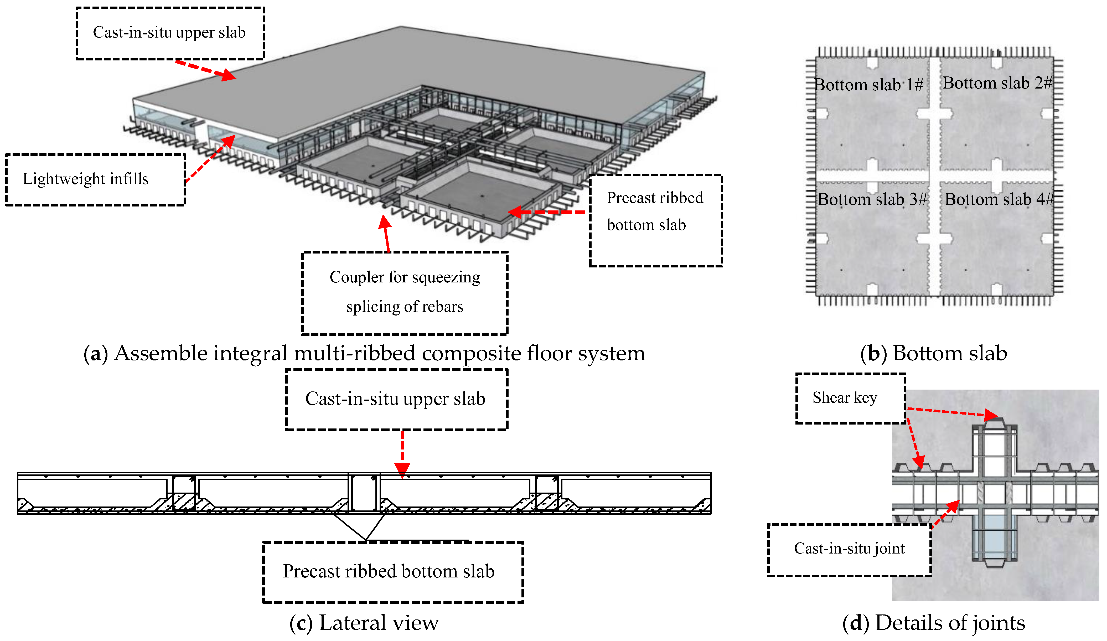
:1. Introduction
2. Experimental Program
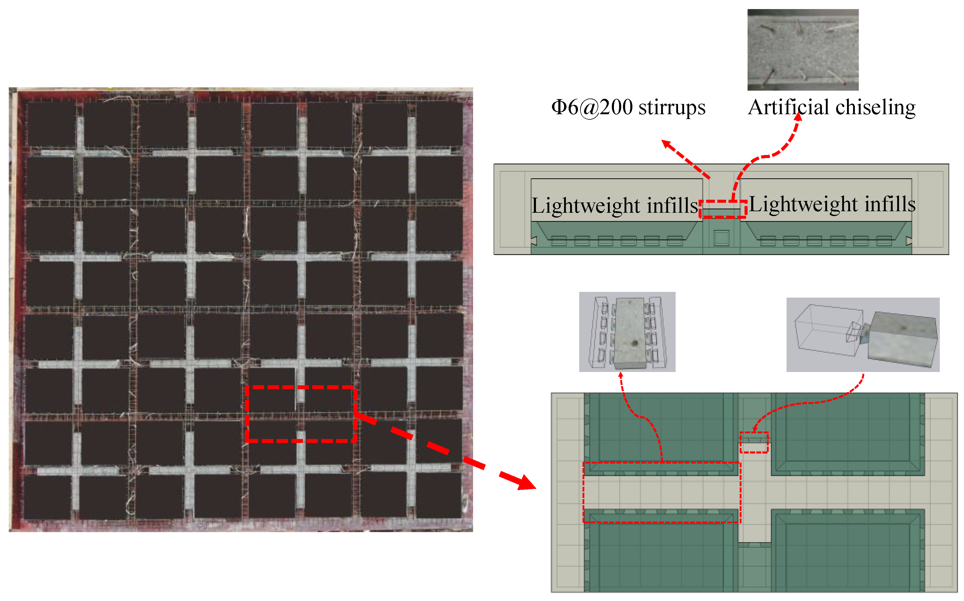
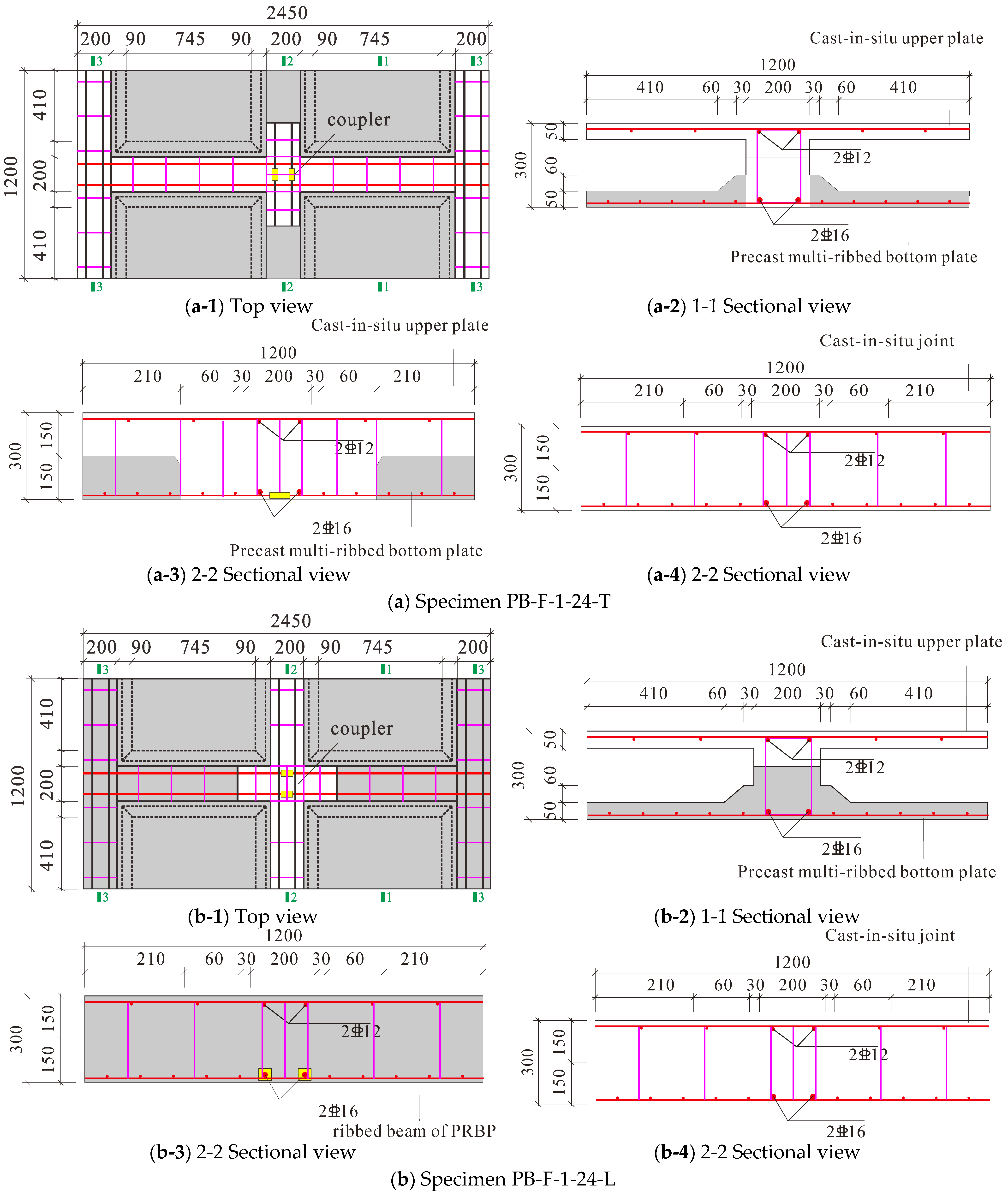
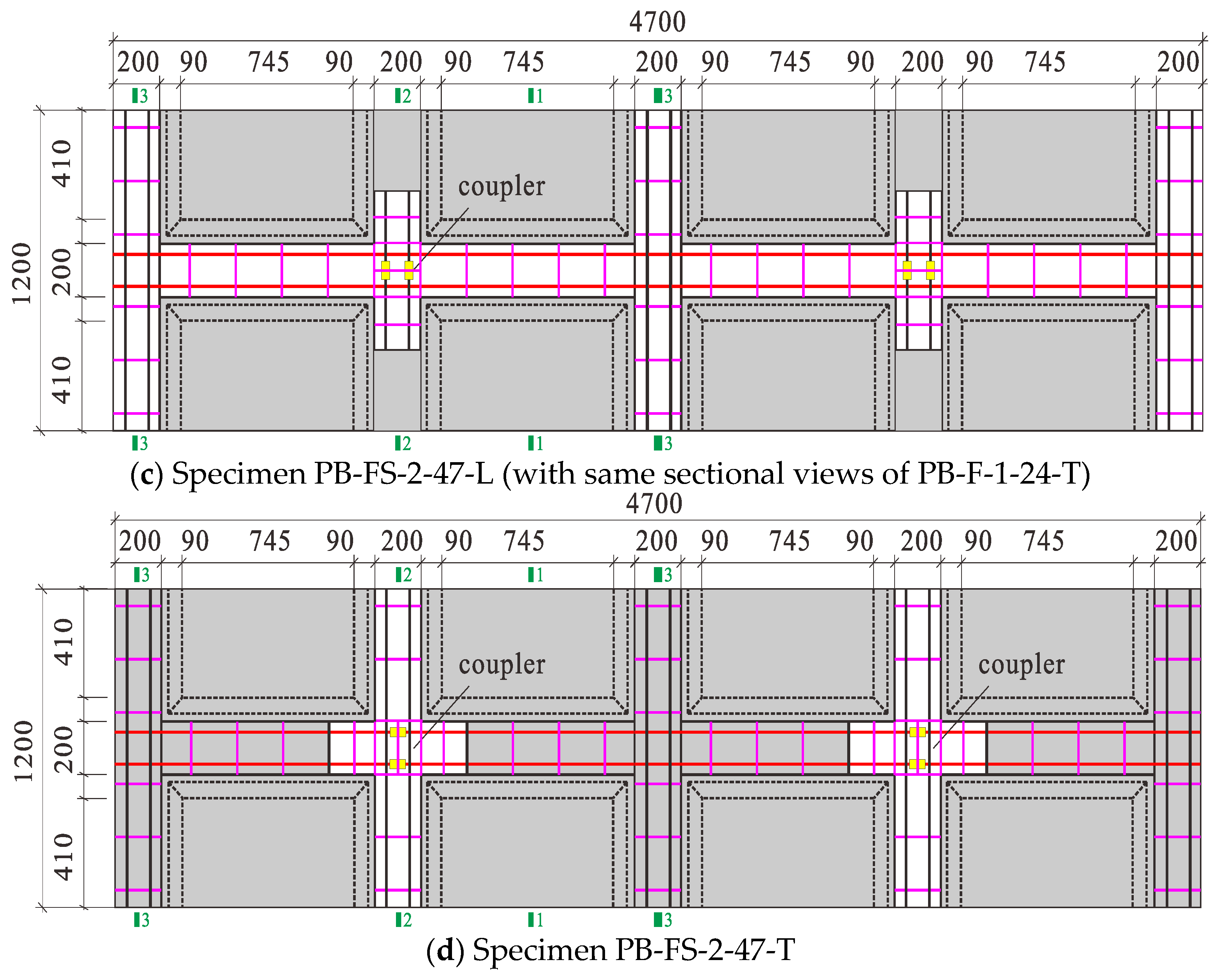
2.1. Specimen Details and Material Properties
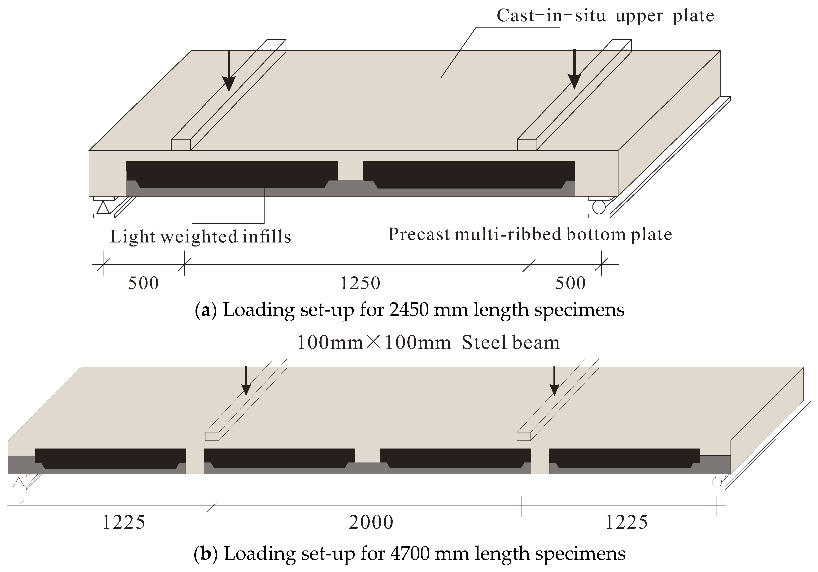
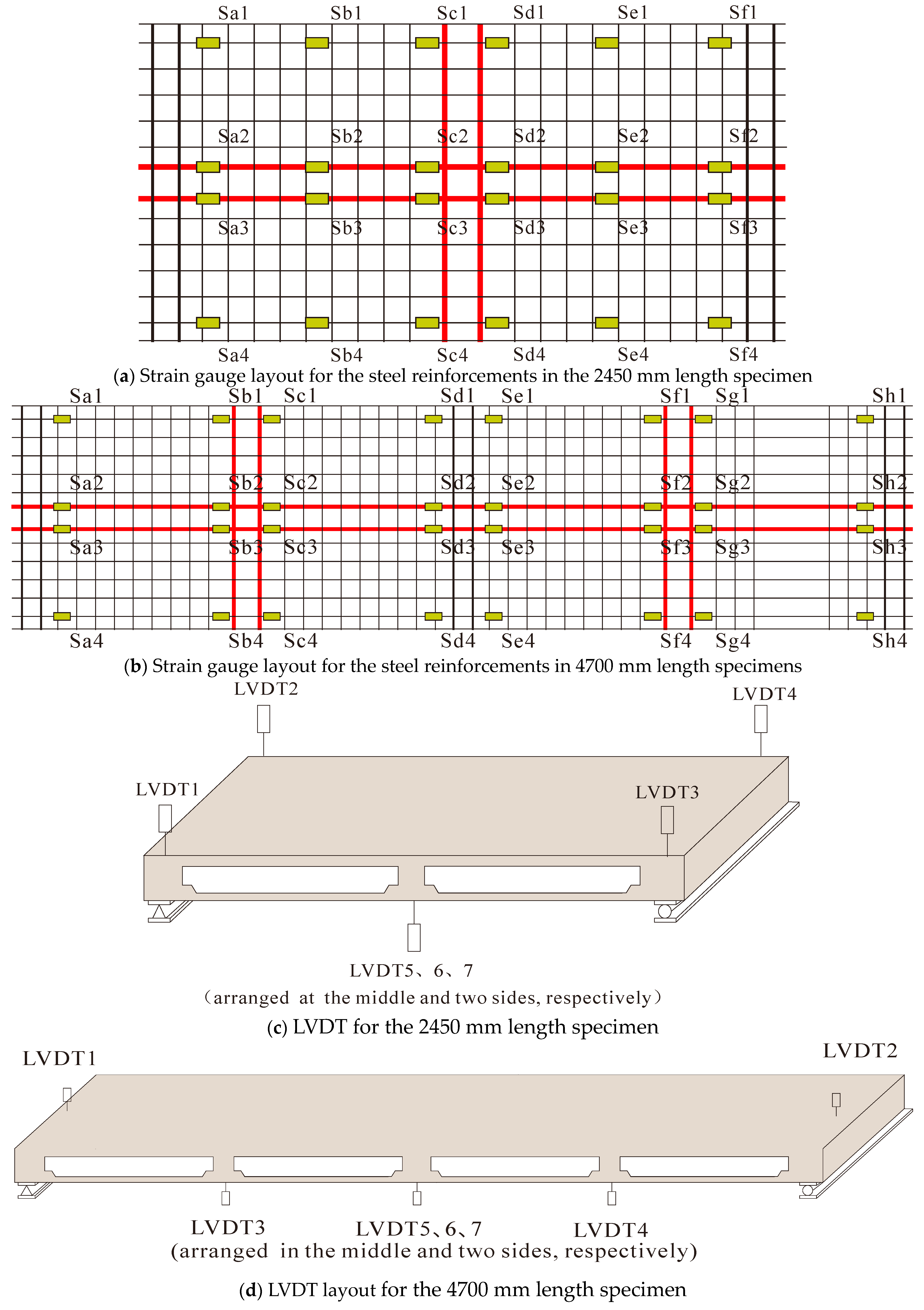
2.2. Test Setup and Measuring System
3. Results and Discussion
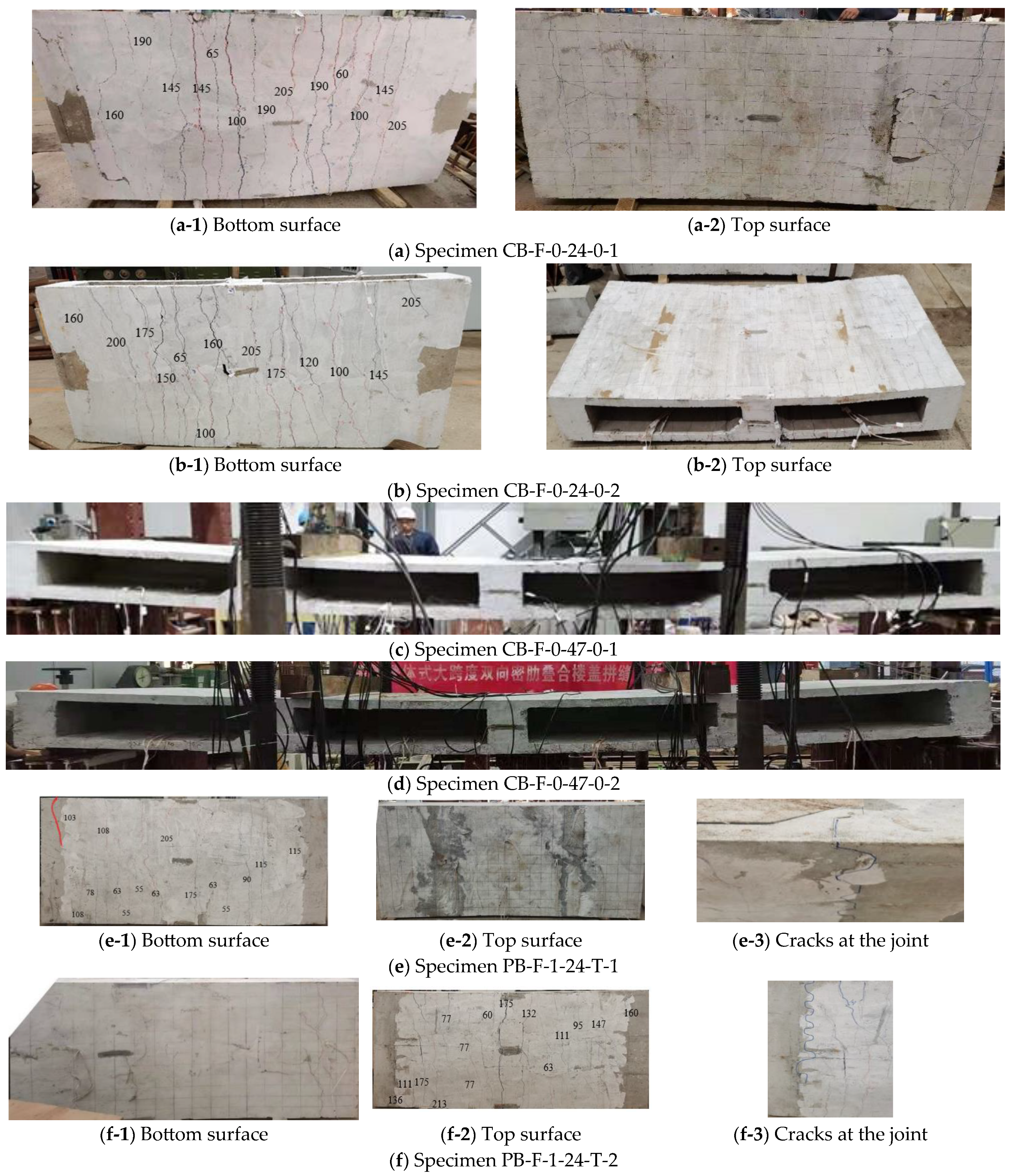
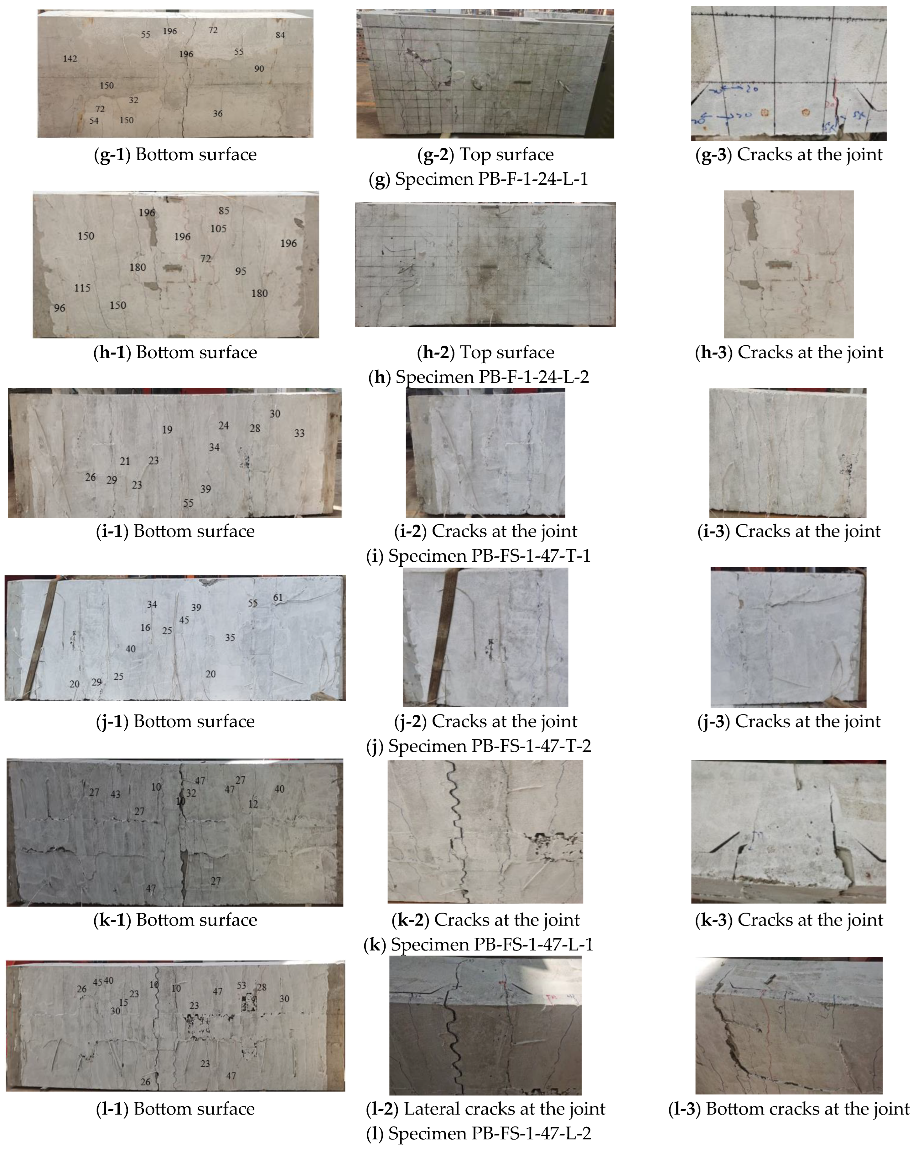
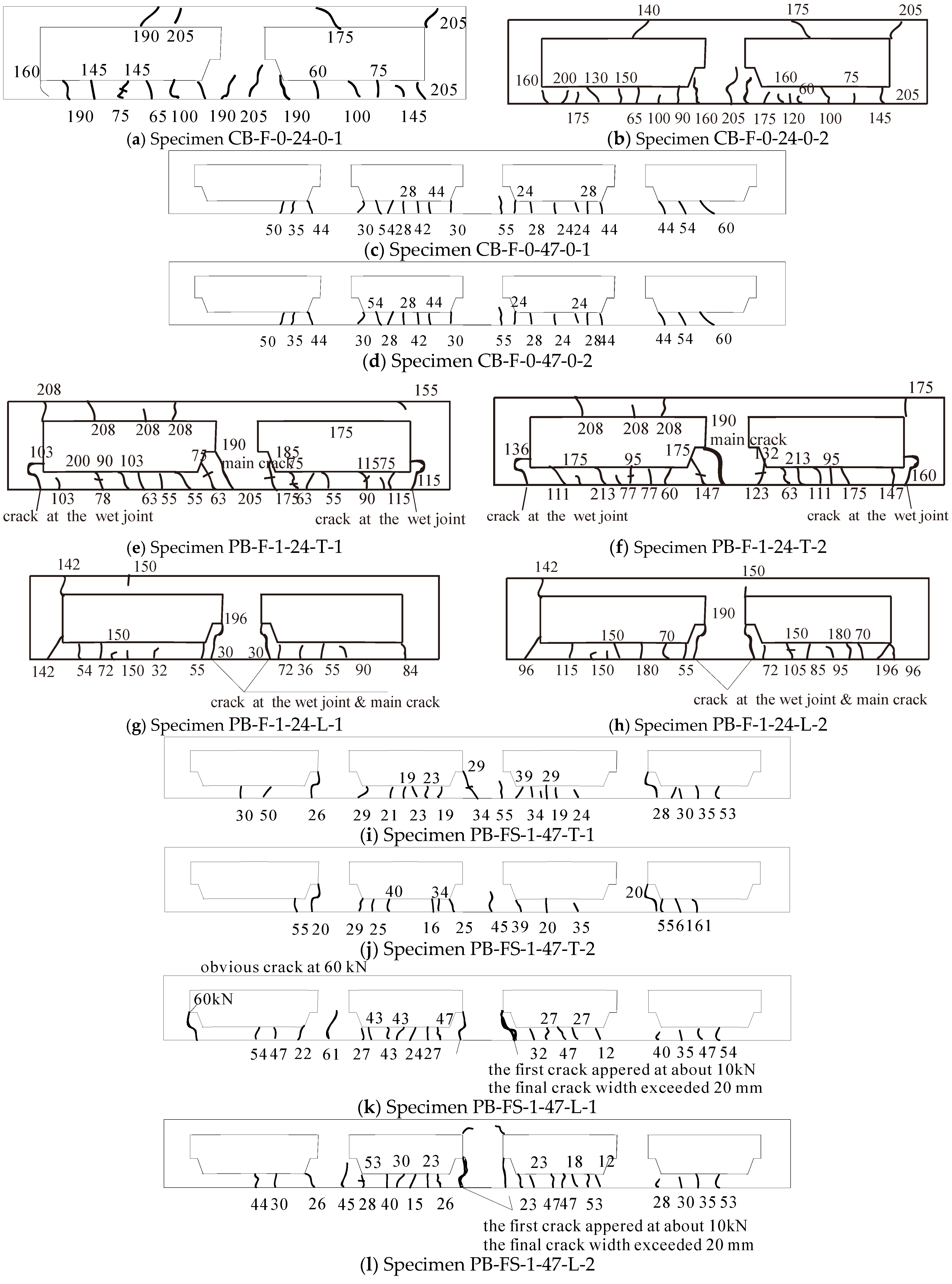
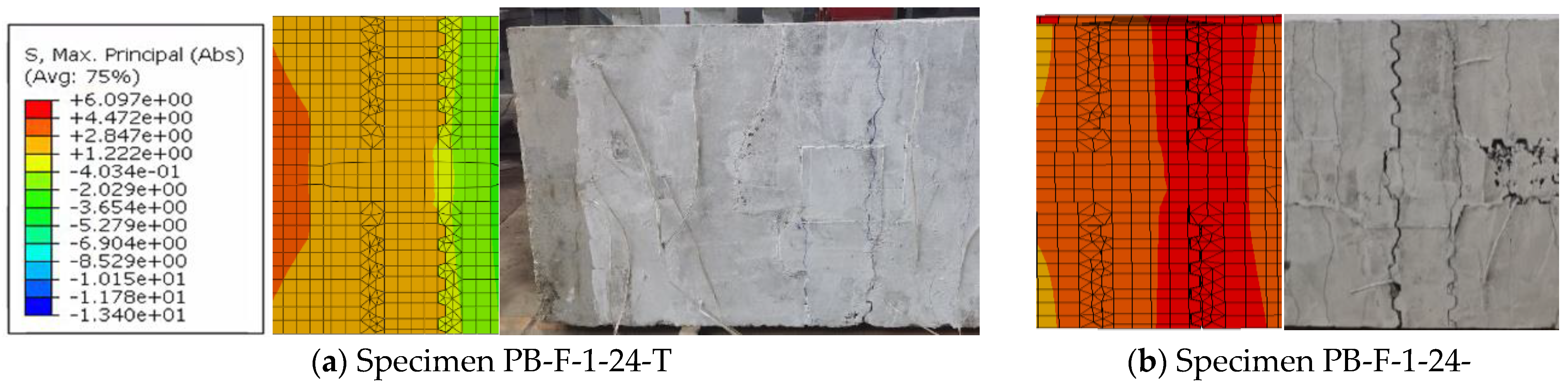
3.1. Failure Modes and Crack Patterns
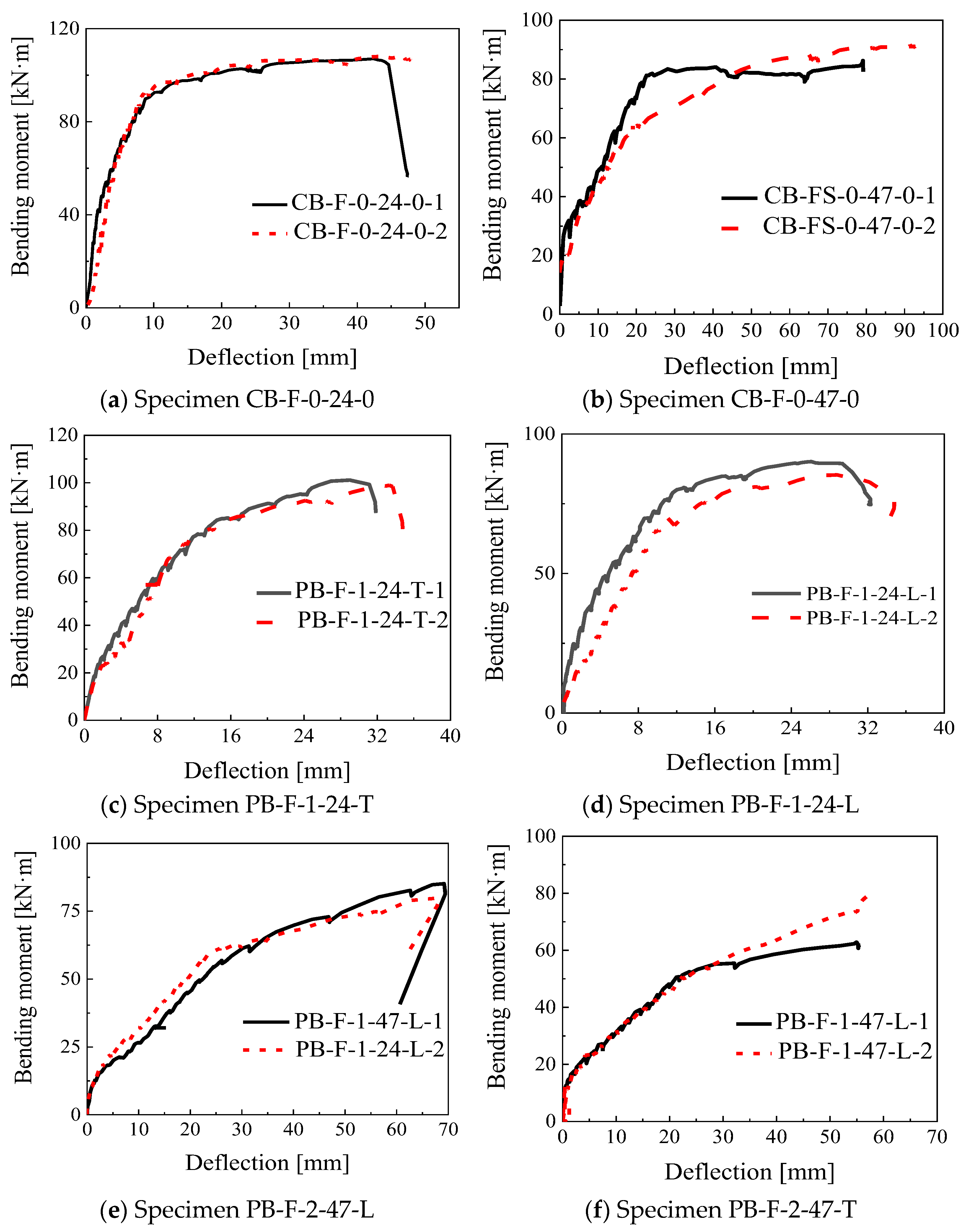
3.2. Moment–Midspan Deflection Relationships
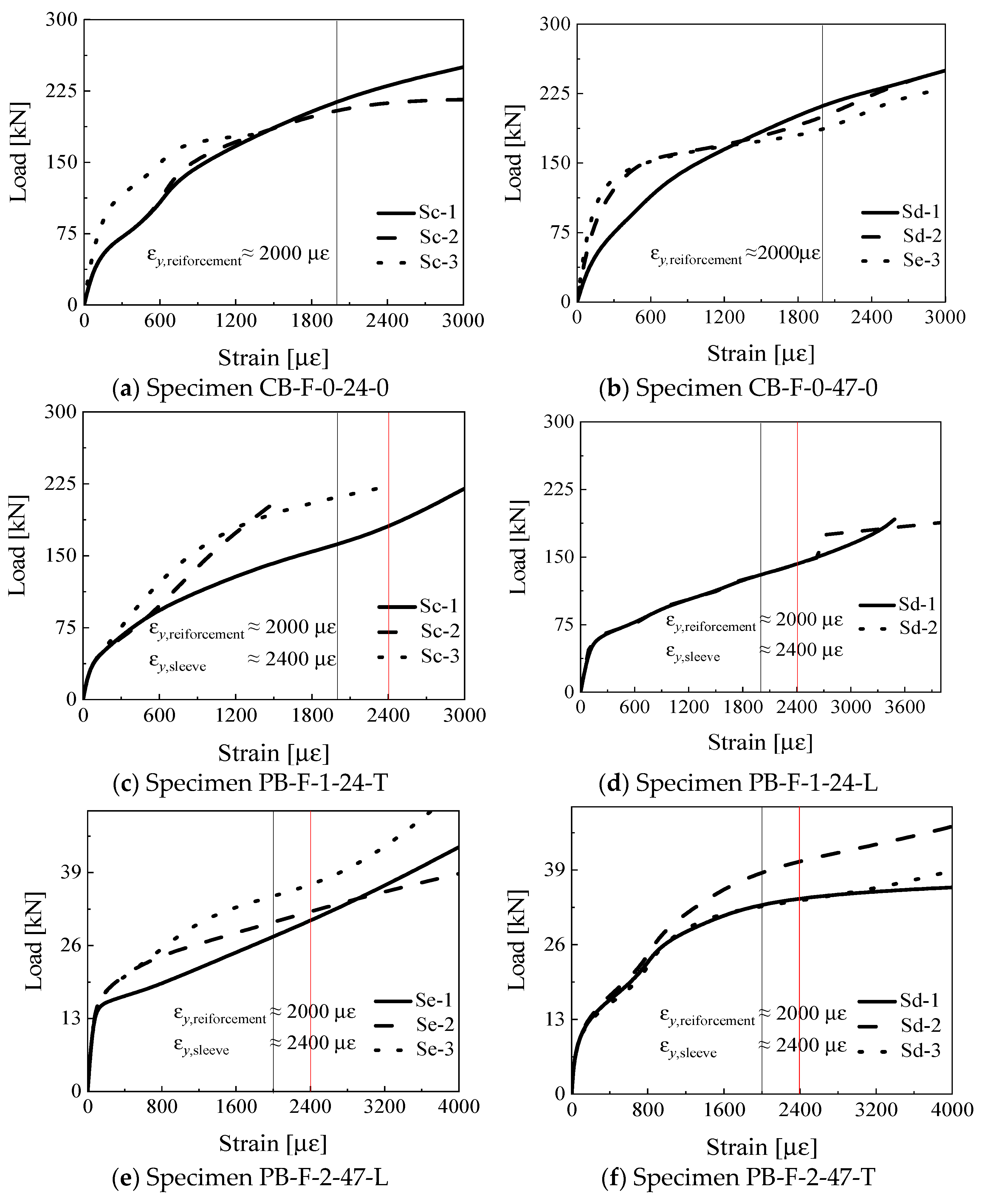
3.3. Strains in the Sleeves and Steel Reinforcements
4. Evaluation of Ultimate Bearing Capacity
5. Finite Element Analysis of Assembly Integral Floor System
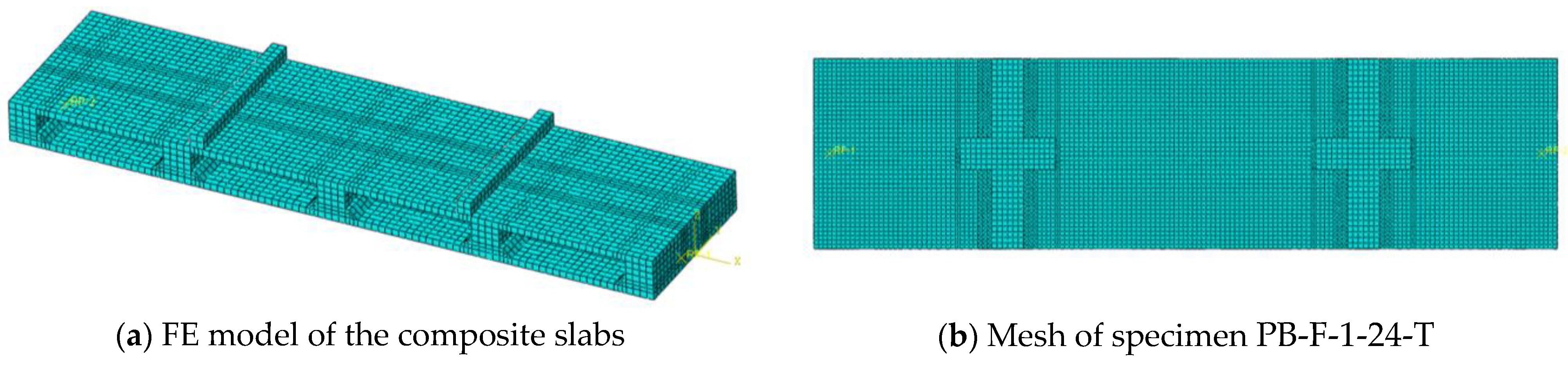
5.1. Finite Element Model
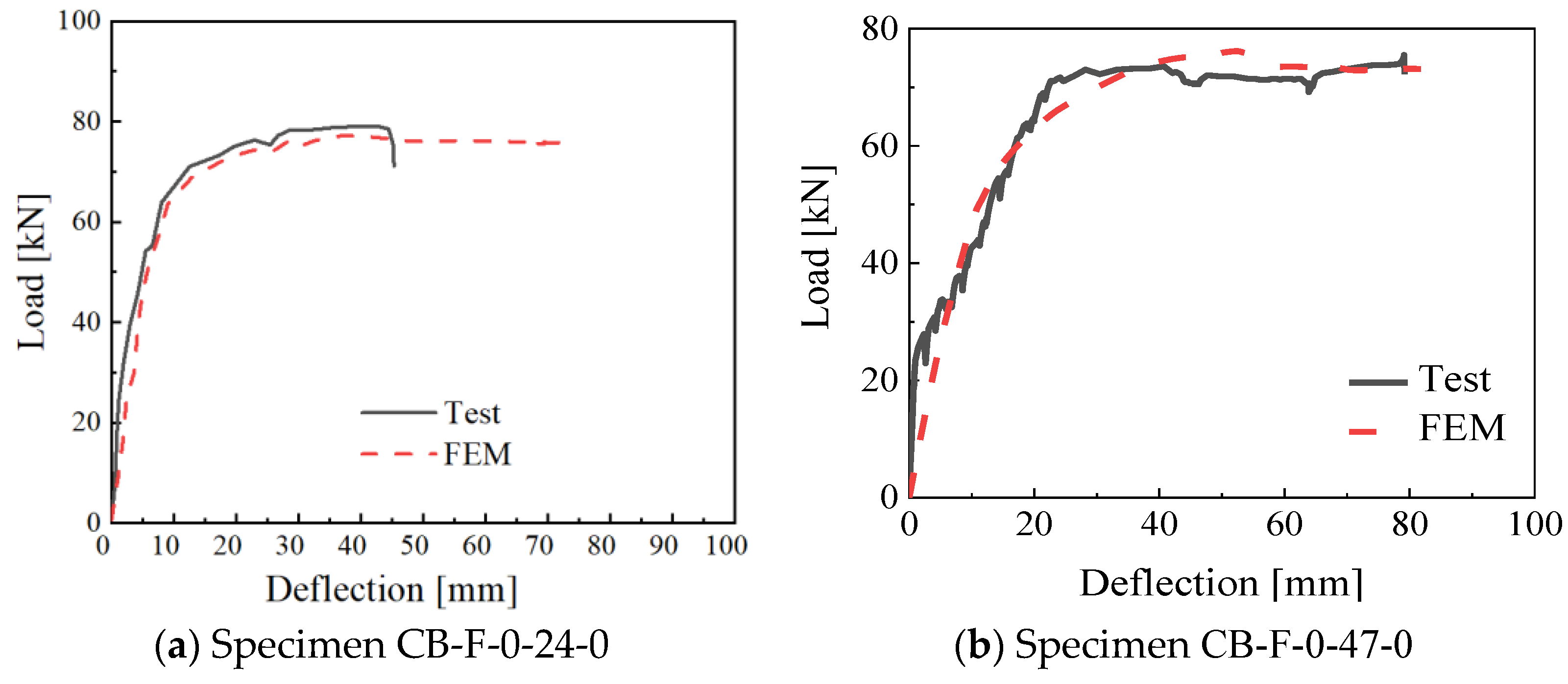
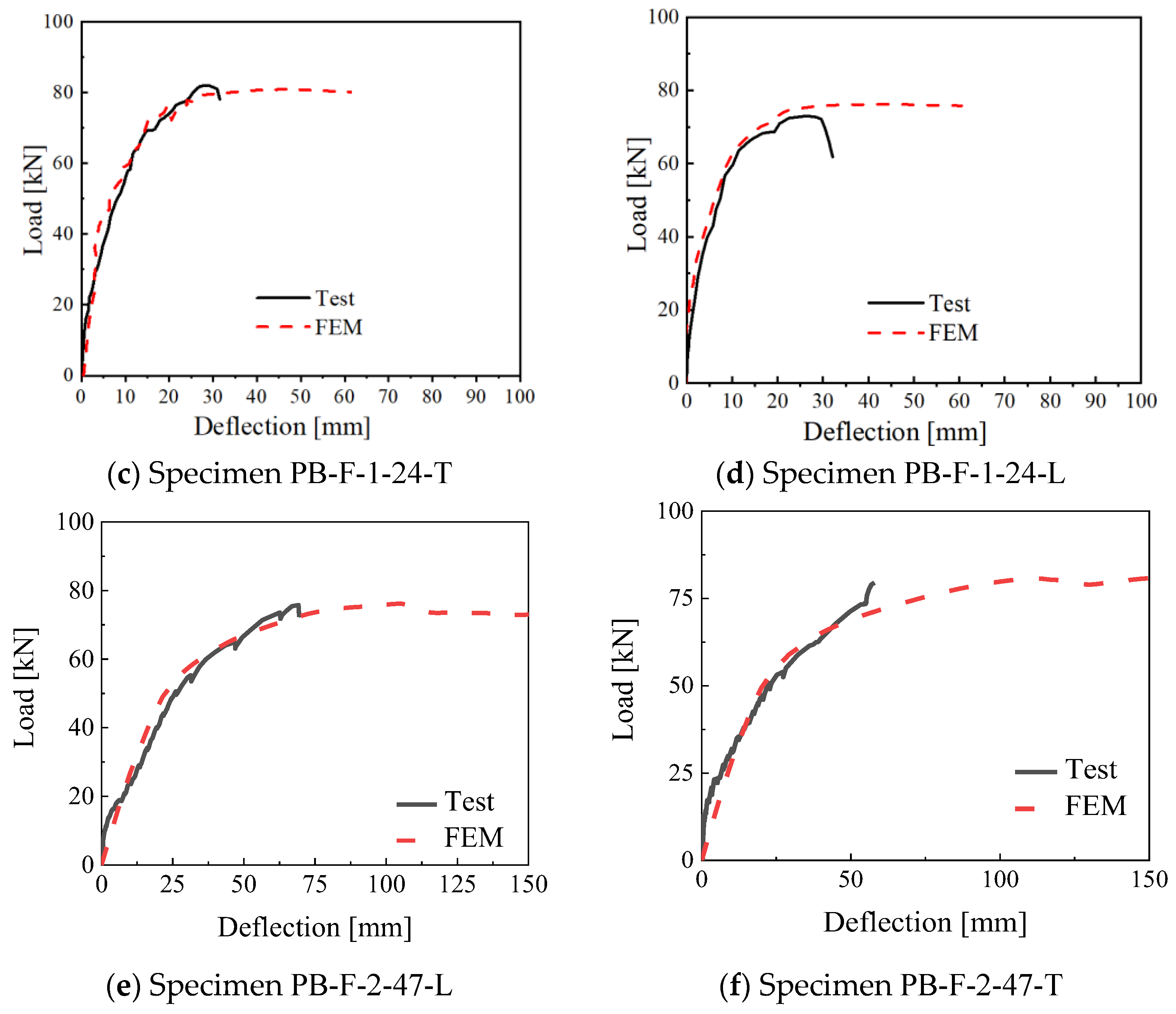
5.2. FE Model Validation and Discussion
6. Conclusions
- (1)
- The precast composite slabs with steel sleeve connections in the joints could provide an ultimate bearing capacity comparable to the cast in situ concrete slabs. The cracks at the cast in situ and precast concrete interface and slip along the longitudinal steel reinforcements led to a smaller cracking load and larger midspan deflection.
- (2)
- The 2450 mm length composite slabs failed in flexural shear, while the flexural failure occurred for 4750 mm length composite slabs, characterized by the maximum crack width. Relative to the cast in situ concrete slabs, the precast composite slab had a relatively lower flexural capacity and stiffness due to interfacial splitting cracks.
- (3)
- No strain difference in the steel sleeves and longitudinal steel reinforcements was observed, and no failure occurring at the wet joints indicated that the proposed sleeve connection ensured reliable load transfer. The sleeve perpendicular to the moment had a minor influence on the interfacial cracking.
- (4)
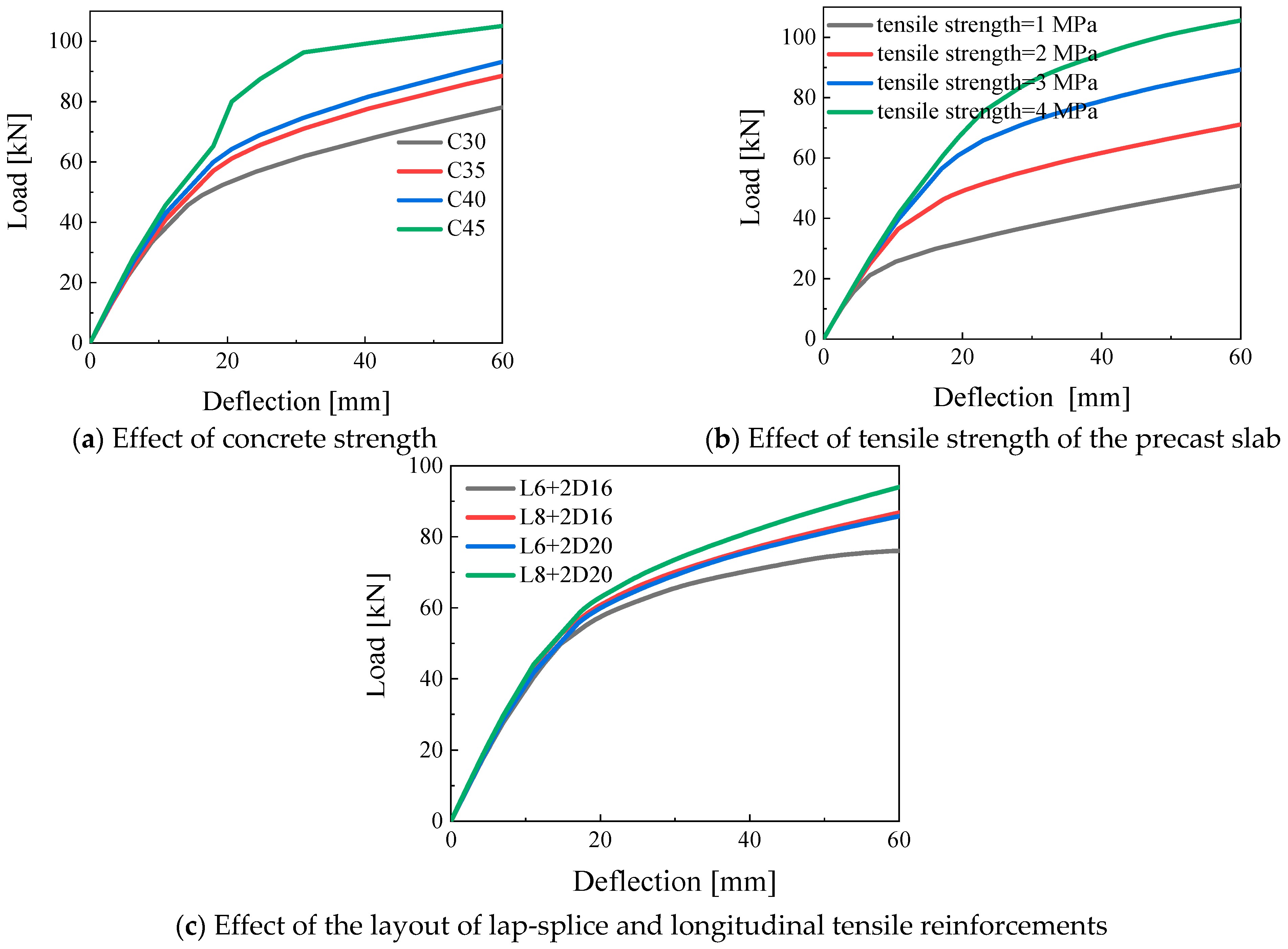
- The tested ultimate moment was about 1.9 times the obtained design values calculated by the Chinese code. FE results indicated the tensile strength in the bottom precast slabs had a more significant influence on the ultimate bearing capacity than the influences of concrete compressive strength and wet joint strength when the connection strength was ensured.
Author Contributions
Funding
Data Availability Statement
Acknowledgments
Conflicts of Interest
References
- Pecce, M.R.; Ceroni, F.; Maddaloni, G. In-plane deformability of RC floors: Assessment of the main parameters and influence on dynamic behaviour. Bull. Earthq. Eng. 2019, 17, 297–311. [Google Scholar] [CrossRef]
- Ahmed, I.M.; Tsavdaridis, K.D. The evolution of composite flooring systems: Applications, testing, modelling and eurocode design approaches. J. Constr. Steel Res. 2019, 155, 286–300. [Google Scholar] [CrossRef]
- Bai, L.; Li, Y.; Hou, C.; Zhou, T.; Cao, M. Longitudinal shear behaviour of composite slabs with profiled steel sheeting and ECC. Eng. Struct. 2020, 205, 110085. [Google Scholar] [CrossRef]
- Cao, X.; Li, X.; Zhu, Y.; Zhang, Z. A comparative study of environmental performance between prefabricated and traditional residential buildings in China. J. Clean. Prod. 2015, 109, 131–143. [Google Scholar] [CrossRef]
- Hou, H.; Liu, X.; Qu, B.; Ma, T.; Liu, H.; Feng, M.; Zhang, B. Experimental evaluation of flexural behavior of composite beams with cast-in-place concrete slabs on precast prestressed concrete decks. Eng. Struct. 2016, 126, 405–416. [Google Scholar] [CrossRef]
- Owolabi, D.; Loss, C. Experimental and numerical study on the bending response of a prefabricated composite CLT-steel floor module. Eng. Struct. 2022, 260, 114278. [Google Scholar] [CrossRef]
- Wang, H.; Liu, X.; Yue, Q.; Zheng, M. Shear resistance of a novel wet connection for prefabricated composite beams under shear-bending coupling loading. J. Build. Eng. 2022, 45, 103636. [Google Scholar] [CrossRef]
- Elamary, A.; Ahmed, M.M.; Mohmoud, A.M. Flexural behaviour and capacity of reinforced concrete–steel composite beams with corrugated web and top steel flange. Eng. Struct. 2017, 135, 136–148. [Google Scholar] [CrossRef]
- Fahmy, M.F.M.; Sayed, A.H.; Farghal, O.A.; Ahmed, A.-E.M. Flexural Behavior of New Hybrid Profiled Steel-FRP T-Beams Filled with Concrete: Development and Validation. J. Compos. Constr. 2020, 24, 04020005. [Google Scholar] [CrossRef]
- Ibrahim, I.S.; Elliott, K.S.; Abdullah, R.; Kueh, A.B.H.; Sarbini, N.N. Experimental study on the shear behaviour of precast concrete hollow core slabs with concrete topping. Eng. Struct. 2016, 125, 80–90. [Google Scholar] [CrossRef]
- Lam, S.S.E.; Wong, V.; Lee, R.S.M. Bonding assessment of semi-precast slabs subjected to flexural load and differential shrinkage. Eng. Struct. 2019, 187, 25–33. [Google Scholar] [CrossRef]
- Machado, W.G.; da Silva, A.R.; das Neves, F. de A. Dynamic analysis of composite beam and floors with deformable connection using plate, bar and interface elements. Eng. Struct. 2019, 184, 247–256. [Google Scholar] [CrossRef]
- Baran, E. Effects of cast-in-place concrete topping on flexural response of precast concrete hollow-core slabs. Eng. Struct. 2015, 98, 109–117. [Google Scholar] [CrossRef]
- Adawi, A.; Youssef, M.A.; Meshaly, M.E. Experimental investigation of the composite action between hollowcore slabs with machine-cast finish and concrete topping. Eng. Struct. 2015, 91, 1–15. [Google Scholar] [CrossRef]
- Yardim, Y.; Waleed, A.M.T.; Jaafar, M.S.; Laseima, S. AAC-concrete light weight precast composite floor slab. Constr. Build. Mater. 2013, 40, 405–410. [Google Scholar] [CrossRef]
- Pang, R.; Zhang, Y.; Dang, L.; Zhang, L.; Liang, S. Experimental and numerical investigation on the vertical bearing behavior of discrete connected new-type precast reinforced concrete floor system. Adv. Struct. Eng. 2020, 23, 2276–2291. [Google Scholar] [CrossRef]
- Li, S.; Chen, W.; Zhang, Y. Flexural behavior of precast, prestressed, lightweight aggregate concrete-conventional concrete composite beams. Constr. Build. Mater. 2021, 274, 121926. [Google Scholar] [CrossRef]
- Qi, J.; Yang, H.-C. Improvement of a Truss-Reinforced, Half-Concrete Slab Floor System for Construction Sustainability. Sustainability 2021, 13, 3731. [Google Scholar] [CrossRef]
- Ghayeb, H.H.; Razak, H.A.; Ramli Sulong, N.H. Performance of dowel beam-to-column connections for precast concrete systems under seismic loads: A review. Constr. Build. Mater. 2020, 237, 117582. [Google Scholar] [CrossRef]
- Chen, Y.; Shi, H.-R.; Wang, C.-L.; Wu, J.; Liao, Z.-Q. Flexural mechanism and design method of novel precast concrete slabs with crossed bent-up rebar. J. Build. Eng. 2022, 50, 104216. [Google Scholar] [CrossRef]
- Huang, Y.; Yang, J.; Zhong, C. Flexural performance of assembly integral floor structure voided with steel mesh boxes. J. Build. Eng. 2022, 54, 104693. [Google Scholar] [CrossRef]
- Deng, B.-Y.; Tan, D.; Li, L.-Z.; Zhang, Z.; Cai, Z.-W.; Yu, K.-Q. Flexural behavior of precast ultra-lightweight ECC-concrete composite slab with lattice girders. Eng. Struct. 2023, 279, 115553. [Google Scholar] [CrossRef]
- Zeng, X.; Feng, Y.; Ruan, S.; Xu, M.; Gong, L. Experimental and Numerical Study on Flexural Behavior of a Full-Scale Assembled Integral Two-Way Multi-Ribbed Composite Floor System. Buildings 2023, 13, 2517. [Google Scholar] [CrossRef]
- GB 50010-2010; Design Code for Concrete Structure. China Architecture & Building Press: Beijing, China, 2017.
- GB/T 50152-2012; Standard for Test Method of Concrete Structures. China Architecture & Building Press: Beijing, China, 2012.
- ABAQUS. Documentation 6.14; Dassault System: Vélizy-Villacoublay, France, 2013. [Google Scholar]
- Figiel, Ł.; Kamiński, M. Numerical Probabilistic Approach to Sensitivity Analysis in a Fatigue Delamination Problem of a Two Layer Composite. Appl. Math. Comput. 2009, 209, 75–90. [Google Scholar] [CrossRef]


| Specimen ID | Joint Amount | Dimension/mm | Sleeve Direction | Loading Type | Casting Method | Duplicate | Sd/mm |
|---|---|---|---|---|---|---|---|
| CB-F-0-24-0 | 0 | 2450 | - | F | Cast in situ | 2 | 1250 |
| CB-FS-0-47-0 | 0 | 4700 | - | FS | Cast in situ | 2 | 2050 |
| PB-F-1-24-T | 1 | 2450 | Transverse | F | Precast | 2 | 1250 |
| PB-F-1-24-L | 1 | 2450 | Longitudinal | F | Precast | 2 | 1250 |
| PB-FS-2-47-L | 2 | 4700 | Longitudinal | FS | Precast | 2 | 2050 |
| PB-FS-2-47-T | 2 | 4700 | Transverse | FS | Precast | 2 | 2050 |
| Specimen ID | CB-F-0-24-0 | CB-FS-0-47-0 | PB-F-1-24-T | PB-F-1-24-L | PB-FS-2-47-L | PB-FS-2-47-T |
|---|---|---|---|---|---|---|
| Ultimate moment/Mu | 111.16 | 105.46 | 103.58 | 96.46 | 99.98 | 95.95 |
| Predicted moment/Mc | 50.28 | 50.28 | 50.28 | 50.28 | 50.28 | 50.28 |
| Mu/Mc | 2.21 | 2.09 | 2.06 | 1.92 | 1.99 | 1.91 |
| Group | Parameters | Values |
|---|---|---|
| G-C-30 | Concrete compressive strength fc (MPa) | fc = 30 |
| G-C-35 | fc = 35 | |
| G-C-40 | fc = 40 | |
| G-C-45 | fc = 45 | |
| G-T-1 | Precast ribbed slab tensile strengths ft (MPa) | ft = 1 |
| G-T-2 | ft = 2 | |
| G-T-3 | ft = 3 | |
| G-T-4 | ft = 4 | |
| G-L6 + 2D16 | Diameter of lap-splice steel rebars (L) and tensile steel reinforcements (D) (mm) | L6 + 2D16 |
| G-L6 + 2D20 | L6 + 2D20 | |
| G-L8 + 2D16 | L8 + 2D16 | |
| G-L8 + 2D20 | L8 + 2D20 |
Disclaimer/Publisher’s Note: The statements, opinions and data contained in all publications are solely those of the individual author(s) and contributor(s) and not of MDPI and/or the editor(s). MDPI and/or the editor(s) disclaim responsibility for any injury to people or property resulting from any ideas, methods, instructions or products referred to in the content. |
© 2024 by the authors. Licensee MDPI, Basel, Switzerland. This article is an open access article distributed under the terms and conditions of the Creative Commons Attribution (CC BY) license (https://creativecommons.org/licenses/by/4.0/).
Share and Cite
Zhang, W.; Feng, Y.; Zeng, X.; Xu, M.; Gong, L.; Rui, L. Flexural Performances of Novel Wet Joints with Sleeve Connections in Precast Composite Floor System. Buildings 2024, 14, 822. https://doi.org/10.3390/buildings14030822
Zhang W, Feng Y, Zeng X, Xu M, Gong L, Rui L. Flexural Performances of Novel Wet Joints with Sleeve Connections in Precast Composite Floor System. Buildings. 2024; 14(3):822. https://doi.org/10.3390/buildings14030822
Chicago/Turabian StyleZhang, Wenbin, Yan Feng, Xiangqiang Zeng, Ming Xu, Liang Gong, and Lijun Rui. 2024. "Flexural Performances of Novel Wet Joints with Sleeve Connections in Precast Composite Floor System" Buildings 14, no. 3: 822. https://doi.org/10.3390/buildings14030822