Figure 1.
Cooperative modular steel building.
Figure 1.
Cooperative modular steel building.
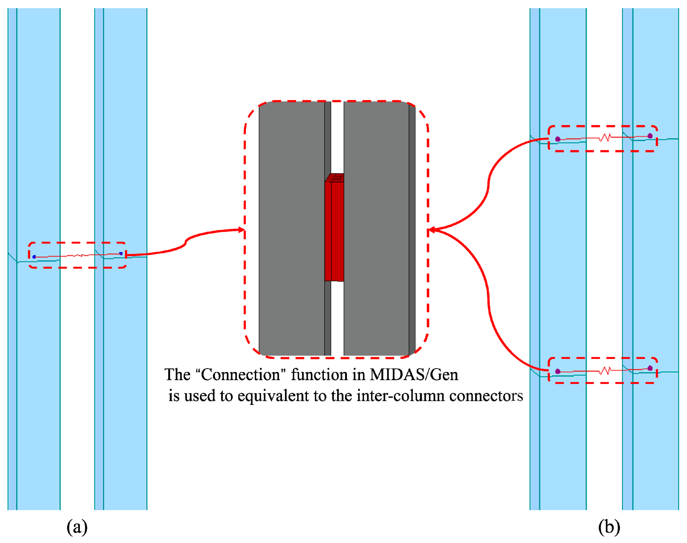
Figure 2.
Connection process of the modular unit columns with an inter-column connector.
Figure 2.
Connection process of the modular unit columns with an inter-column connector.
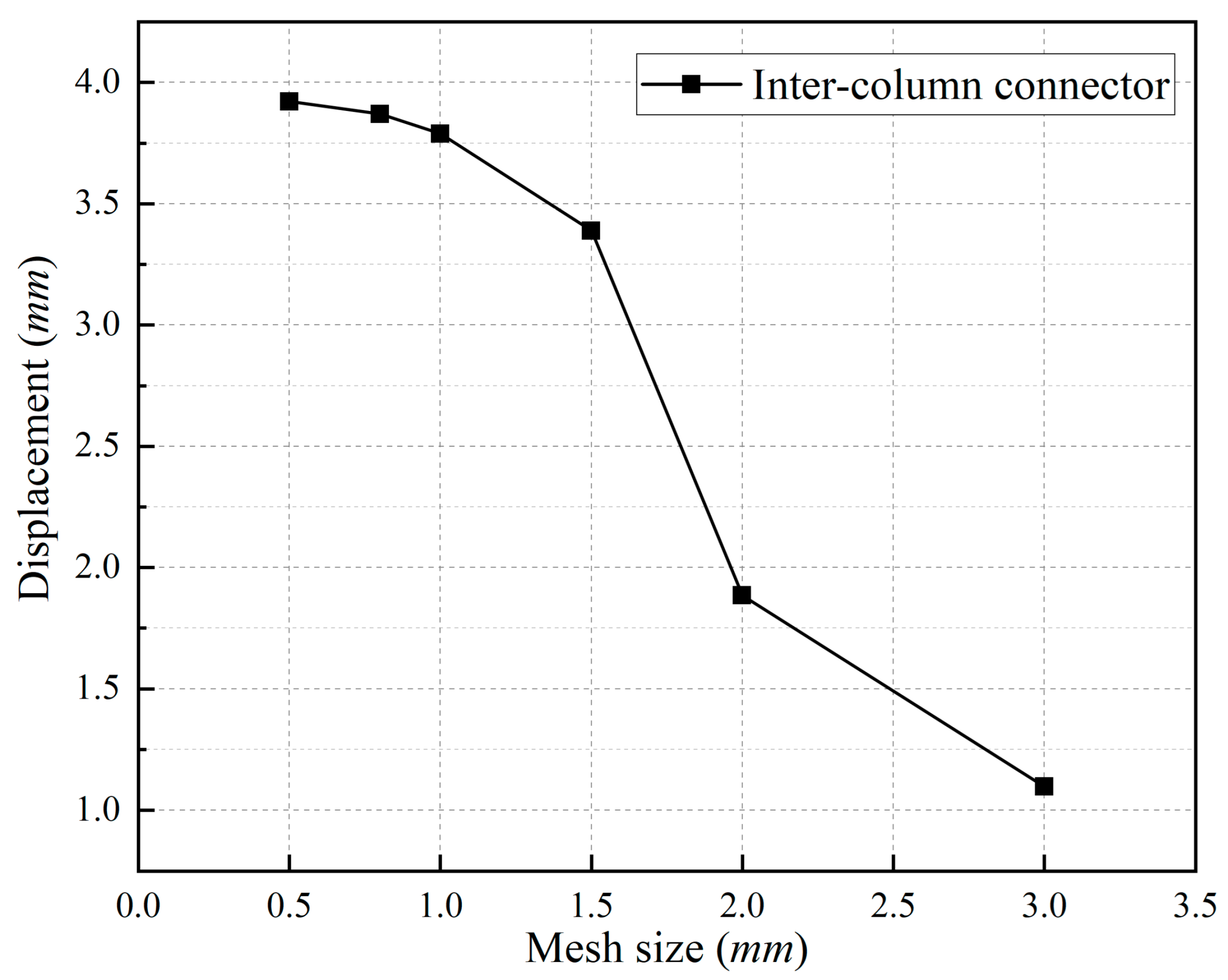
Figure 3.
The change in the final displacement of the convex connector with the change in mesh density.
Figure 3.
The change in the final displacement of the convex connector with the change in mesh density.
Figure 4.
A finite element model of an inter-column connector.
Figure 4.
A finite element model of an inter-column connector.
Figure 5.
Dimensions of an inter-column connector.
Figure 5.
Dimensions of an inter-column connector.
Figure 6.
The connection mode of vertical modular units in MIDAS/Gen.
Figure 6.
The connection mode of vertical modular units in MIDAS/Gen.
Figure 7.
The connection mode of the horizontal modular unit in MIDAS/Gen: (a) The number of arrangements is one; (b) The number of arrangements is two.
Figure 7.
The connection mode of the horizontal modular unit in MIDAS/Gen: (a) The number of arrangements is one; (b) The number of arrangements is two.
Figure 8.
Cooperative modular steel building standard floor layout.
Figure 8.
Cooperative modular steel building standard floor layout.
Figure 9.
Types of modular units: (a) Module-1; (b) Module-2; (c) Module-3.
Figure 9.
Types of modular units: (a) Module-1; (b) Module-2; (c) Module-3.
Figure 10.
Time history curve of seismic wave: Frequent earthquake: (a) Elcent–h; (b) RH2TG055; (c) Artificial. Rare occurrence earthquake: (d) Elcent–h; (e) RH2TG055; (f) Artificial.
Figure 10.
Time history curve of seismic wave: Frequent earthquake: (a) Elcent–h; (b) RH2TG055; (c) Artificial. Rare occurrence earthquake: (d) Elcent–h; (e) RH2TG055; (f) Artificial.
Figure 11.
Comparison of the first three modes of the structure: (a) The first vibration mode: translation in the X-direction; (b) The second vibration mode: translation in the X-direction; (c) The third vibration mode: torsion.
Figure 11.
Comparison of the first three modes of the structure: (a) The first vibration mode: translation in the X-direction; (b) The second vibration mode: translation in the X-direction; (c) The third vibration mode: torsion.
Figure 12.
Inter-story displacement angle of a modular steel building with different seismic fortification intensities: (a) 7-degree (0.10 g) in the X-direction; (b) 7-degree (0.15 g) in the X-direction; (c) 8-degree (0.20 g) in the X-direction; (d) 7-degree (0.10 g) in the Y-direction; (e) 7-degree (0.15 g) in the Y-direction; (f) 8-degree (0.20 g) in the Y-direction.
Figure 13.
The inter-story displacement angle of the modular steel building when the peak acceleration of the earthquake is 35 cm/s2: (a) Elcent–h wave in the X-direction; (b) RH2TG055 wave in the X-direction; (c) Artificial wave in the X-direction; (d) Elcent–h wave in the Y-direction; (e) RH2TG055 wave in the Y-direction; (f) Artificial wave in the Y-direction.
Figure 14.
The inter-story displacement angle of the modular steel building when the peak acceleration of the earthquake is 55 cm/s2: (a) Elcent–h wave in the X-direction; (b) RH2TG055 wave in the X-direction; (c) Artificial wave in the X-direction; (d) Elcent–h wave in the Y-direction; (e) RH2TG055 wave in the Y-direction; (f) Artificial wave in the Y-direction.
Figure 15.
The inter-story displacement angle of the modular steel building when the peak acceleration of the earthquake is 70 cm/s2: (a) Elcent–h wave in the X-direction; (b) RH2TG055 wave in the X-direction; (c) Artificial wave in the X-direction; (d) Elcent–h wave in the Y-direction; (e) RH2TG055 wave in the Y-direction; (f) Artificial wave in the Y-direction.
Figure 16.
The top displacement of the modular steel building when the seismic peak acceleration is 220 cm/s2: (a) Elcent–h; (b) RH2TG055; (c) Artificial.
Figure 16.
The top displacement of the modular steel building when the seismic peak acceleration is 220 cm/s2: (a) Elcent–h; (b) RH2TG055; (c) Artificial.
Figure 17.
The top displacement of the modular steel building when the seismic peak acceleration is 310 cm/s2: (a) Elcent–h; (b) RH2TG055; (c) Artificial.
Figure 17.
The top displacement of the modular steel building when the seismic peak acceleration is 310 cm/s2: (a) Elcent–h; (b) RH2TG055; (c) Artificial.
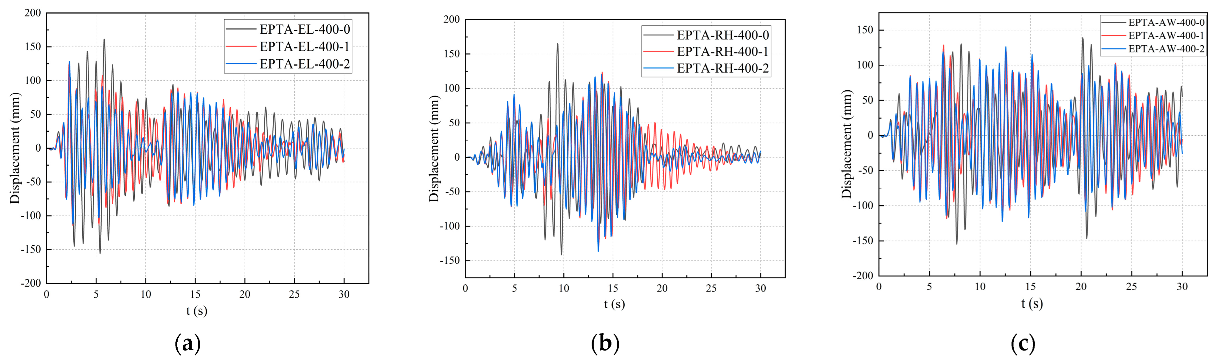
Figure 18.
The top displacement of the modular steel building when the seismic peak acceleration is 400 cm/s2: (a) Elcent–h; (b) RH2TG055; (c) Artificial.
Figure 18.
The top displacement of the modular steel building when the seismic peak acceleration is 400 cm/s2: (a) Elcent–h; (b) RH2TG055; (c) Artificial.
Figure 19.
The inter-story displacement angle of the modular steel building when the peak acceleration of the earthquake is 220 cm/s2: (a) Elcent–h; (b) RH2TG055; (c) Artificial.
Figure 19.
The inter-story displacement angle of the modular steel building when the peak acceleration of the earthquake is 220 cm/s2: (a) Elcent–h; (b) RH2TG055; (c) Artificial.
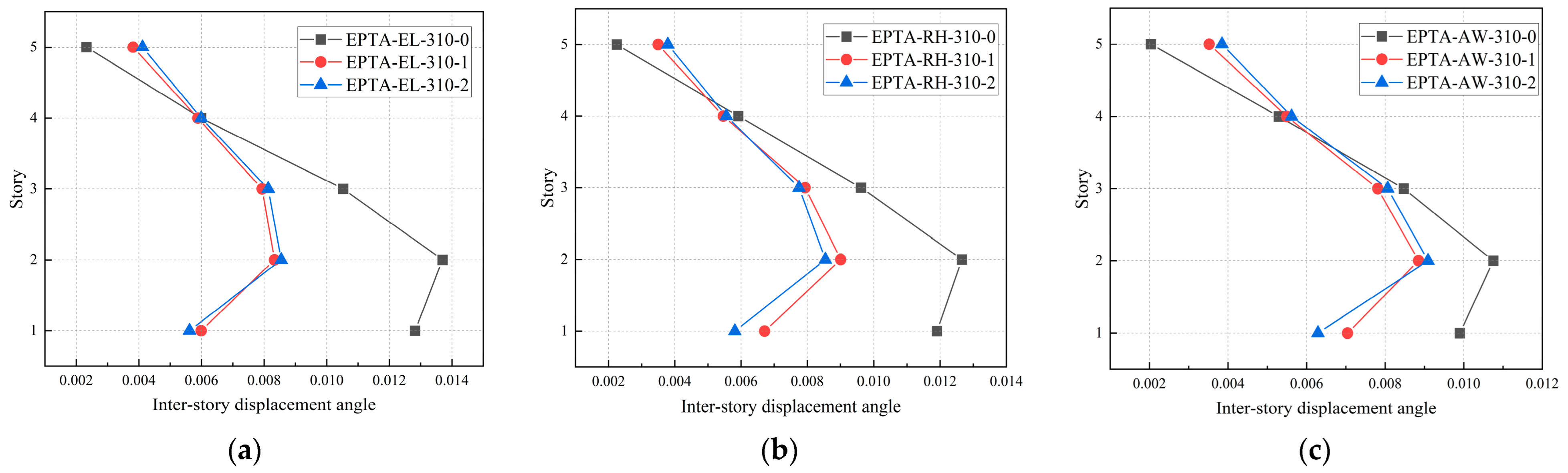
Figure 20.
The inter-story displacement angle of the modular steel building when the peak acceleration of the earthquake is 310 cm/s2: (a) Elcent–h; (b) RH2TG055; (c) Artificial.
Figure 20.
The inter-story displacement angle of the modular steel building when the peak acceleration of the earthquake is 310 cm/s2: (a) Elcent–h; (b) RH2TG055; (c) Artificial.
Figure 21.
The inter-story displacement angle of the modular steel building when the peak acceleration of the earthquake is 400 cm/s2: (a) Elcent–h; (b) RH2TG055; (c) Artificial.
Figure 21.
The inter-story displacement angle of the modular steel building when the peak acceleration of the earthquake is 400 cm/s2: (a) Elcent–h; (b) RH2TG055; (c) Artificial.
Figure 22.
The base shear of the modular steel building when the peak acceleration of the earthquake is 220 cm/s2: (a) Elcent–h; (b) RH2TG055; (c) Artificial.
Figure 22.
The base shear of the modular steel building when the peak acceleration of the earthquake is 220 cm/s2: (a) Elcent–h; (b) RH2TG055; (c) Artificial.
Figure 23.
The base shear of the modular steel building when the peak acceleration of the earthquake is 310 cm/s2: (a) Elcent–h; (b) RH2TG055; (c) Artificial.
Figure 23.
The base shear of the modular steel building when the peak acceleration of the earthquake is 310 cm/s2: (a) Elcent–h; (b) RH2TG055; (c) Artificial.
Figure 24.
The base shear of the modular steel building when the peak acceleration of the earthquake is 400 cm/s2: (a) Elcent–h; (b) RH2TG055; (c) Artificial.
Figure 24.
The base shear of the modular steel building when the peak acceleration of the earthquake is 400 cm/s2: (a) Elcent–h; (b) RH2TG055; (c) Artificial.
Figure 25.
Modular steel building standard-story module layout.
Figure 25.
Modular steel building standard-story module layout.
Figure 26.
Variation of interlayer displacement angle when the number of connectors is one: (a) HA-7-1; (b) HA-7.5-1; (c) HA-8-1.
Figure 26.
Variation of interlayer displacement angle when the number of connectors is one: (a) HA-7-1; (b) HA-7.5-1; (c) HA-8-1.
Figure 27.
Variation of the maximum stress ratio when the number of connectors is one: (a) HA-7-1; (b) HA-7.5-1; (c) HA-8-1.
Figure 27.
Variation of the maximum stress ratio when the number of connectors is one: (a) HA-7-1; (b) HA-7.5-1; (c) HA-8-1.
Figure 28.
Variation of interlayer displacement angle when the number of connectors is two: (a) HA-7-1; (b) HA-7.5-1; (c) HA-8-1.
Figure 28.
Variation of interlayer displacement angle when the number of connectors is two: (a) HA-7-1; (b) HA-7.5-1; (c) HA-8-1.
Figure 29.
Variation of the maximum stress ratio when the number of connectors is two: (a) HA-7-1; (b) HA-7.5-1; (c) HA-8-1.
Figure 29.
Variation of the maximum stress ratio when the number of connectors is two: (a) HA-7-1; (b) HA-7.5-1; (c) HA-8-1.
Table 1.
Model parameter design.
Table 1.
Model parameter design.
| Model Parameter | Load Direction | Load Displacement |
|---|
| M1 | U1 | 1 mm |
| M2 | U2 | −1 mm |
| M3 | U3 | 1 mm |
| M4 | UR1 | 0.01 rad |
| M5 | UR2 | 0.01 rad |
| M6 | UR3 | 0.01 rad |
Table 2.
The initial stiffness of each degree of freedom of the inter-column connector.
Table 2.
The initial stiffness of each degree of freedom of the inter-column connector.
| Direction of Freedom | Initial Stiffness |
|---|
| Dx | 4309.1 × 103 kN/m |
| Dy | 3543.5 × 103 kN/m |
| Dz | 2556.3 × 103 kN/m |
| Rx | 47,541.4 kN·m/rad |
| Ry | 77,080.9 kN·m/rad |
| Rz | 1123.8 kN·m/rad |
Table 3.
Structural section size.
Table 3.
Structural section size.
| Type of Member | Section Dimensions
(mm) | Materials Chosen |
|---|
| Modular columns | 200 × 200 × 8 | Q345 |
| Floor beams | 220 × 140 × 6 | Q345 |
| Ceiling beams | 150 × 100 × 6 | Q345 |
| Support | 140 × 140 × 4 | Q235 |
| Ceiling | 20 (board thickness) | C30 |
| Floor | 120 (board thickness) | C30 |
Table 4.
Model parameters of response spectrum analysis.
Table 4.
Model parameters of response spectrum analysis.
| Model Number | Seismic Fortification Intensity | Number of Inter-Column Connectors |
|---|
| RSA-7-0 | 7 degrees (0.10 g) | 0 |
| RSA-7-1 | 7 degrees (0.10 g) | 1 |
| RSA-7-2 | 7 degrees (0.10 g) | 2 |
| RSA-7.5-0 | 7 degrees (0.15 g) | 0 |
| RSA-7.5-1 | 7 degrees (0.15 g) | 1 |
| RSA-7.5-2 | 7 degrees (0.15 g) | 2 |
| RSA-8-0 | 8 degrees (0.20 g) | 0 |
| RSA-8-1 | 8 degrees (0.20 g) | 1 |
| RSA-8-2 | 8 degrees (0.20 g) | 2 |
Table 5.
Model parameters of time history analysis.
Table 5.
Model parameters of time history analysis.
| Model Number | Seismic Wave Number | Maximum Value of the Seismic Acceleration (cm/s2) | Number of Inter-Column Connectors | Model Number | Seismic Wave Number | Maximum Value of the Seismic Acceleration (cm/s2) | Number of Inter-Column Connectors |
|---|
| ETA-EL-35-0 | EL | 35 | 0 | EPTA-EL-220-0 | EL | 220 | 0 |
| ETA-EL-35-1 | EL | 35 | 1 | EPTA-EL-220-1 | EL | 220 | 1 |
| ETA-EL-35-2 | EL | 35 | 2 | EPTA-EL-220-2 | EL | 220 | 2 |
| ETA-RH-35-0 | RH | 35 | 0 | EPTA-RH-220-0 | RH | 220 | 0 |
| ETA-RH-35-1 | RH | 35 | 1 | EPTA-RH-220-1 | RH | 220 | 1 |
| ETA-RH-35-2 | RH | 35 | 2 | EPTA-RH-220-2 | RH | 220 | 2 |
| ETA-AW-35-0 | AW | 35 | 0 | EPTA-AW-220-0 | AW | 220 | 0 |
| ETA-AW-35-1 | AW | 35 | 1 | EPTA-AW-220-1 | AW | 220 | 1 |
| ETA-AW-35-2 | AW | 35 | 2 | EPTA-AW-220-2 | AW | 220 | 2 |
| ETA-EL-55-0 | EL | 55 | 0 | EPTA-EL-310-0 | EL | 310 | 0 |
| ETA-EL-55-1 | EL | 55 | 1 | EPTA-EL-310-1 | EL | 310 | 1 |
| ETA-EL-55-2 | EL | 55 | 2 | EPTA-EL-310-2 | EL | 310 | 2 |
| ETA-RH-55-0 | RH | 55 | 0 | EPTA-RH-310-0 | RH | 310 | 0 |
| ETA-RH-55-1 | RH | 55 | 1 | EPTA-RH-310-1 | RH | 310 | 1 |
| ETA-RH-55-2 | RH | 55 | 2 | EPTA-RH-310-2 | RH | 310 | 2 |
| ETA-AW-55-0 | AW | 55 | 0 | EPTA-AW-310-0 | AW | 310 | 0 |
| ETA-AW-55-1 | AW | 55 | 1 | EPTA-AW-310-1 | AW | 310 | 1 |
| ETA-AW-55-2 | AW | 55 | 2 | EPTA-AW-310-2 | AW | 310 | 2 |
| ETA-EL-70-0 | EL | 70 | 0 | EPTA-EL-400-0 | EL | 400 | 0 |
| ETA-EL-70-1 | EL | 70 | 1 | EPTA-EL-400-1 | EL | 400 | 1 |
| ETA-EL-70-2 | EL | 70 | 2 | EPTA-EL-400-2 | EL | 400 | 2 |
| ETA-RH-70-0 | RH | 70 | 0 | EPTA-RH-400-0 | RH | 400 | 0 |
| ETA-RH-70-1 | RH | 70 | 1 | EPTA-RH-400-1 | RH | 400 | 1 |
| ETA-RH-70-2 | RH | 70 | 2 | EPTA-RH-400-2 | RH | 400 | 2 |
| ETA-AW-70-0 | AW | 70 | 0 | EPTA-AW-400-0 | AW | 400 | 0 |
| ETA-AW-70-1 | AW | 70 | 1 | EPTA-AW-400-1 | AW | 400 | 1 |
| ETA-AW-70-2 | AW | 70 | 2 | EPTA-AW-400-2 | AW | 400 | 2 |
Table 6.
Structural natural vibration period of different models.
Table 6.
Structural natural vibration period of different models.
| Seismic Fortification Intensity | Model Number | Natural Vibration Period (s) |
|---|
| 7 degrees (0.10 g) | RSA-7-0 | 0.830 |
| RSA-7-1 | 0.659 |
| RSA-7-2 | 0.636 |
| 7 degrees (0.15 g) | RSA-7.5-0 | 0.830 |
| RSA-7.5-1 | 0.659 |
| RSA-7.5-2 | 0.636 |
| 8 degrees (0.20 g) | RSA-8-0 | 0.830 |
| RSA-8-1 | 0.659 |
| RSA-8-2 | 0.636 |
Table 7.
Top displacement of modular steel buildings with different seismic fortification intensities.
Table 7.
Top displacement of modular steel buildings with different seismic fortification intensities.
| Seismic Fortification Intensity | Model Number | Top Displacement (mm) |
|---|
| X-Direction | Y-Direction |
|---|
| 7 degrees (0.10 g) | RSA-7-0 | 14.16 | 10.77 |
| RSA-7-1 | 11.86 | 9.90 |
| RSA-7-2 | 11.62 | 9.65 |
| 7 degrees (0.15 g) | RSA-7.5-0 | 21.24 | 16.15 |
| RSA-7.5-1 | 17.79 | 14.85 |
| RSA-7.5-2 | 17.43 | 14.47 |
| 8 degrees (0.20 g) | RSA-8-0 | 28.32 | 21.53 |
| RSA-8-1 | 23.72 | 19.80 |
| RSA-8-2 | 23.24 | 19.29 |
Table 8.
Model parameters suitable for height analysis.
Table 8.
Model parameters suitable for height analysis.
| Model Number | Seismic Fortification Intensity | Number of Inter-Column Connectors |
|---|
| HA-7-1 | 7 degrees (0.10 g) | 1 |
| HA-7.5-1 | 7 degrees (0.15 g) | 1 |
| HA-8-1 | 8 degrees (0.20 g) | 1 |
| HA-7-2 | 7 degrees (0.10 g) | 2 |
| HA-7.5-2 | 7 degrees (0.15 g) | 2 |
| HA-8-2 | 8 degrees (0.20 g) | 2 |
Table 9.
The maximum applicable height of the cooperative modular steel building system.
Table 9.
The maximum applicable height of the cooperative modular steel building system.
| Number of Inter-Column Connectors | Seismic Fortification Intensity | Number of Stories | Applicable Height
(m) |
|---|
| 1 | 7 degrees (0.10 g) | 7 | 21 |
| 7 degrees (0.15 g) | 7 | 21 |
| 8 degrees (0.20 g) | 4 | 12 |
| 2 | 7 degrees (0.10 g) | 7 | 21 |
| 7 degrees (0.15 g) | 7 | 21 |
| 8 degrees (0.20 g) | 4 | 12 |
Table 10.
The maximum applicable height of the modular steel building stipulated in the T/CECS 507-2018
technical specification for steel structure modular buildings [
18].
Table 10.
The maximum applicable height of the modular steel building stipulated in the T/CECS 507-2018
technical specification for steel structure modular buildings [
18].
| Seismic Fortification Intensity | Number of Stories | Applicable Height
(m) |
|---|
| 7 degrees (0.10 g) | 3 | 9 |
| 7 degrees (0.15 g) | 3 | 9 |
| 8 degrees (0.20 g) | 1~2 | 3~6 |


