Article

Reduced Volume Approach to Evaluate Biaxial Bubbled Slabs’ Resistance to Punching Shear

1
Department of Civil Engineering, College of Engineering, University of Baghdad, Baghdad 17001, Iraq
2
Department of Civil Engineering, College of Engineering, University of Kirkuk, Kirkuk 36001, Iraq
3
L2MGC—Civil Engineering Mechanics and Materials Laboratory, CY Cergy-Paris University, 95031 Neuville-sur-Oise, France
*
Author to whom correspondence should be addressed.
Buildings 2024, 14(3), 676; https://doi.org/10.3390/buildings14030676
Submission received: 31 January 2024 / Revised: 22 February 2024 / Accepted: 1 March 2024 / Published: 3 March 2024
(This article belongs to the Special Issue Advances in Building Materials and Methods)

Abstract

:
The bubbled slab, a type of reinforced concrete (RC) slab with plastic voids, is an innovative design that employs a biaxial distribution of voiding formers within the slab to reduce the slab’s self-weight while preserving a load-carrying capacity that is approximately comparable to that of solid slabs. This paper presents a new approach for figuring out the effective critical shear perimeter of voided slabs using the reduced-volume concept of concrete. This approach aims to reduce the coefficient of variation of the current design standards, namely the ACI 318-19 and Eurocode 2, for assessing the slabs’ resistance to punching shear. Our experimental program investigated the impact of voiding former patterns and the location of an opening near a column on the punching shear resistance of biaxial hollow slabs. The factors under consideration included the opening’s size, location, and distance from the loaded area, as well as the voiding formers’ placement concerning the critical shear boundaries. The results of experiments on 10 full-scale, 2000 × 2000 × 230 mm, reinforced concrete biaxial voided slabs with an opening are presented in this study. Two design expressions were used to estimate the biaxial hollow slabs’ shear strength. These expressions take into account the reduced volume of concrete and the distribution of voiding formers up to the section 4 d from the periphery of the column. The proposed approach to determine the effective punching shear perimeter has the lowest coefficient of variation among the methods suggested by these standards. This indicates the validity of our proposed expressions. The coefficient of variation of the proposed expressions does not exceed 0.057.

1. Introduction

Large areas for interior circulation are frequently required in the construction of commercial and industrial structures. Thus, it is crucial to increase the spacing between columns in the building layout to increase the gap between slab supports.
By minimizing the structure’s self-weight, void slabs aim to maximize the benefits of concrete slab construction while reducing the disadvantages of solid slabs [1]. It is not feasible to replace all of the internal concrete because the aggregate interlock plays a vital role in shear resistance. The concrete in the top area of the slab forms the compression block necessary for flexural resistance. Additionally, the concrete in the tension zone of the slab needs to bond with reinforcement to enhance the effectiveness of the reinforcement for flexural resistance [2,3,4]. The flanges at the top and bottom of the section are preserved, as high stresses can be generated there.
Accordingly, plastic voiding formers are used to replace the ineffective concrete in the middle of the slab cross-section, which has a limited effect on and contribution to the slab’s strength to resist an applied load, allowing for longer spans with the same load capacity. Using inverted plastic injection-molded elements (Airdeck), elliptical and tour hollow plastic elements (Cobiax), U-boot voiding elements, the Unidome system, Bee plate system, or hollow plastic sphere (bubble) technologies, the voiding formers may become spheres, ellipses, cubes, or other shapes [5,6,7,8].
The biaxial hollow deck module was first developed in Europe in the 1990s by Danish structural Engineer Jorgen Breuning [9]. It is based on a flat slab that extends in two directions and is voided. The entire slab is then supported by various supporting structures at different points, while a solid portion is retained to transfer the load from the hollow slab to the supporting structures. This slab system can effectively function under both positive and negative bending moments [10,11].

2. Literature Review on the Strength of Biaxial Voided Slabs

2.1. Punching Shear Strength of Biaxial Voided Slabs

To evaluate the punching shear capacity of reinforced concrete flat slabs, extensive research has been conducted in the past and continues to be carried out. Many researchers have investigated the performance of solid reinforced concrete flat slabs when a punching failure has occurred under their point loads [12,13,14,15,16,17,18,19,20]. Studies have indicated that a cone-shaped perforation is created during punching shear failure, with the angle varying from 26.6 to 45 degrees with regard to the base. The critical shear perimeter calculation technique is largely dependent on how the failure cone is defined. This in turn influences the punching shear strength calculation techniques, which can differ based on the cone’s definition [12,14,21]. The possibility of a brittle failure at the column periphery can compromise the structural integrity of reinforced concrete flat slabs, leading to gradual collapse.
The hollow formers’ shape, which is included when generating the required cavities, determines the punching shear behavior of such structural slabs [21,22]. Increasing the level of hollowness of biaxial hollow slabs has impacts on their overall stiffness, affecting their capability to withstand loads, deformability, and resistance to cracking [23].
One of the most significant and interesting features of biaxial hollow slabs is their punching shear resistance. Zones subjected to concentrated loads, particularly the slab–column connection area, are the most vulnerable and crucial areas of the biaxial hollow slab. In comparison to solid slabs, experimental research on biaxial hollow slabs has shown that the punching shear region’s perimeter drastically decreased during failure [15,21,24,25,26,27].
The building practice codes currently in use [28,29] contain empirical equations that help in predicting the punching shear resistance of reinforced concrete flat slabs. The statistical fitting of experimental data available at the time of the codes’ development serves as their foundation. As a result, various formulas have been presented to estimate the strength of solid slabs against punching shear.
The critical shear perimeter is defined at ( 0.5 d ) from the column face in the ACI 318-19 code [28]. The Eurocode 2 [29] has adopted almost the farthest critical perimeter, which is advised to be ( 2 d ) from the column’s face, see Figure 1.
Calculations for the critical shear perimeter and, in turn, the punching shear resistance of a solid cross-sectional slab cannot be used directly for voided reinforced concrete slabs. A calculation approach to a biaxial hollow slab’s punching shear resistance needs to be suggested and refined through theoretical and experimental investigations [13,16,30].
Numerous factors can impact a biaxial voided slab’s punching shear capacity, including the void’s size, pattern, shape, and distance from the column face [1,2,3,5,6,9,10,11,15,21,23,24,25,26,27,31,32,33,34].
A study by Valivonis et al. [21,22] examined six biaxial reinforced concrete voided slabs both theoretically and experimentally. Three sets of two void slab specimens were constructed and tested until they failed. In the first group, the regions that were predicted to be punching shear-prone were solid and void-free; nevertheless, in the second group, these were equipped with voiding formers. Meanwhile, the third set of slabs was filled with solid cross-shaped beams and voids. Based on the design codes for solid concrete slabs (the ACI 318-19 and Eurocode 2), the theoretical punching shear strength of voided slabs was determined. A thorough analysis was performed to compare the theoretical and experimental findings. After modifications to account for the presence of voiding formers in the punching shear zone, it was obvious that techniques for evaluating a solid RC slab’s punching shear capacity might also be used for voided slabs. Using the TNO Diana 2011 software, a numerical simulation using the finite element method was carried out to investigate the slab’s stress condition. A computer model of the tested voided slab was built to precisely represent the steel in the tension and compression zones as well as the voiding formers. The bottom flange of the slab has a substantial impact on its punching shear strength, as seen by the finite element method’s results. Consequently, Valivonis et al. [21,22] proposed an approach for calculating the punching shear perimeter for biaxial hollow slabs that assesses the impact of the concrete flanges that exist over voids inside the punching zone. Upon comparing the experimental outcomes with the predicted punching shear capacities, estimated using the Eurocode 2 and ACI 318-19 design code, it was evident that the modifications made to the European design code accurately captured the punching shear performance of biaxial hollow slabs. There was only an average 4.3% discrepancy between the theory and the punching shear capacities recorded in the experiment.
The impact of ball shapes (elliptical or spherical) and ball spacing (25 or 70 mm) on slab behavior and strength was investigated in a study by Ibrahim et al. [34]. Five 1850 × 460 × 110 mm slabs were cast and tested using recycled plastic balls. The study’s findings proved that, in comparison to solid slabs, voided slabs exhibited 90–96% of the maximum load of solid RC slabs, as well as greater deflection (7.8–21%) at their ultimate load and a smaller first cracking load (6.7–16%). Furthermore, even with the same volume of concrete reduction, slabs with spherical-shaped balls demonstrated a higher bearing efficiency than slabs with elliptical-shaped voiding formers.
Oukaili and Hussein [35] conducted a detailed experimental and analytical investigation of the performance of self-compacting RC biaxial voided slabs exposed to concentric or eccentric loads. Static testing was performed on 24 half-scale square specimens that were constructed with a side length of 1500 mm and a thickness of 100 or 130 mm. The primary factors were the diameter of the plastic voiding formers, the concrete’s compressive strength, the location of the applied load about the column stub’s longitudinal axis (i.e., load with or without eccentricity), and the distribution pattern of the voiding formers in relation to the adopted critical shear section (i.e., farther than d or 2 d from the column stub’s face). The punching shear resistance of the biaxial voided slabs in this investigation was found to be lower than that of solid RC slabs. Nonetheless, this decrease was around 4–20% and 15–29% in voided slabs with voiding formers distributed farther than the section 2 d from and the section d from the column stub’s border, respectively.
An analytical investigation was carried out by Bhagat and Parikh [15] to compare solid flat slabs and reinforced concrete voided slabs. SAP2000–Version 15.0.1 integrated software was utilized for both the structural analysis and design. Slabs with a square configuration were investigated, which had an interior span ranging from 6 m to 14 m, an overall thickness ranging from 280 mm to 600 mm, and voiding formers’ diameters ranging from 180 mm to 450 mm. The same procedure implemented for solid RC slabs was applied to simulate and model the voided specimens. The test results showed that the RC bubbled specimens were less stiff than the solid slabs. For specific bubbled slabs, a reduction factor for stiffness and the solid region of the critical shear perimeter were therefore calculated. It was observed that the stiffness of the voided slabs decreases with increasing slab thickness. Additionally, the stiffness reduction factor was discovered to lie between 0.8 and 0.9, indicating that the insertion of plastic spheres resulted in a stiffness reduction of approximately 10–20%.
Gajewski et al. [36] successfully achieved the optimal design of bubbled deck slabs, minimizing concrete usage while meeting Eurocode serviceability standards. The combination of numerical homogenization and sequential quadratic programming proved efficient, reducing concrete weight by 23%. The approach had demonstrated computational advantages, providing accurate results in a few hours without the need for computationally expensive finite element methods. This method preserves the complex structure of bubble deck slabs without relying on less accurate shape simplifications.

2.2. Impact of Opening on Strength of Flat Slabs

It should be noted that, occasionally, slab openings are necessary to allow for the installation of pipes and utility ducts. The formation of an opening near to a column removes a portion of the effective concrete that resists shear forces, which further reduces the column–slab connection’s punching shear capacity. Numerous investigations were carried out to examine the performance of solid RC slabs with openings by Hognestad et al. [37], Broms [12,38], El-Salakawy et al. [39], Teng et al. [40], Borges et al. [18], Hegger et al. [13], and Oukaili and Al-Gasham [41]. The detrimental impact of forming these openings needs to be counteracted. Openings reduce the overall (shear and flexural) stiffness as well as the ductility of the slab by eliminating a portion of its concrete volume, which lowers the shear strength of the slab–column connection. While substantial experimental studies have been conducted on reinforced concrete flat slabs with openings that perforate close to columns [18,40,42,43,44], there remains a lack of comprehensive research regarding their punching strengths.
To account for the impact of openings close to supports, the ACI 318-19 [28] deducts the lengths between lines that radiate from the support’s central point and tangent to the openings’ extremities, reducing the control perimeters’ lengths. The method is the same in the Eurocode 2 [29], except l 2 is substituted with ( l 1 l 2 ) if the opening’s dimension in the transversal direction ( l 2 ) is larger than its dimension ( l 1 ) in the radial direction. Despite being extremely straightforward, this radial projection technique may not make much sense [14]. It seems unlikely that an opening of a given size would occur on the long side of a rectangular support, where the shear would be more detrimental since the shear stress is anticipated to be concentrated close to the short sides. This technique also does not account for any negative effects that can result from the uneven shear imposed by an asymmetrical arrangement of openings. According to the findings of Borges et al. [18], the direct projection of opening widths onto the control shear perimeters yielded more reliable strength predictions for slabs without shear reinforcement than any other type of radial projection when determining the reductions in the concrete’s contributions to resisting punching. Nonetheless, it is likely essential to take into account the eccentricity effects between the column (support) and the residual shear perimeter if utilizing a straight projection.
El-Shafiey et al.’s study [45] analyzed the influence of opening parameters on the punching behavior of RC flat slabs. Ten two-way slabs of 1600 × 1600 × 120 mm were subjected to static loads. The purpose of the study was to determine how shear performance was affected by an opening’s size, shape, and position. The adjacent openings to the column measured 200 × 200 mm, 300 × 300 mm, and 400 × 400 mm. Three different spacings were considered for the opening border and column faces: 100 mm, 200 mm, and 300 mm. Slabs with circular openings were tested to explore the impact of the opening shape. These data were compared with the square openings’ areas. The diameters of the openings were 250, 350, and 450 mm. According to the test data, when the size of the opening increased, the slabs’ capacity and stiffness significantly reduced. However, by employing a circular opening or extending the distance between the column and the opening, the scale of this decrease can be lowered. Comparing the experimental shear capabilities of tested specimens with openings to the results of the ACI318-19 [28] and Eurocode 2 [29] codes’ equations revealed that the Eurocode 2 has lower factors of safety than the ACI 318-19 code.
To inspect the critical opening location and the control shear perimeter, Al-Rousan and Alnemrawi [46] investigated a variety of code rules about shear resistance in RC two-way flat slabs without using shear reinforcement. The impact of various opening sizes and locations on twenty-one simulated models was investigated using a nonlinear finite element evaluation conducted using ABAQUS 2020 software. The analysis considered opening positions at z e r o , 0.25 d , 0.5 d , 2 d , 4 h , 5.5 d , and 6 d , in addition to opening sizes of 100, 200, and 300 mm. According to the findings, the critical punching perimeter’s suggested value of 0.5 d is the most reliable. Furthermore, the point at which the impact of an opening, regardless of its size, can be ignored was found to be sufficiently determined by a value of 4 h , where h is the tested slab’s total thickness. The research findings indicate that the accuracy of the punching shear capacity estimations by various codes is greatly influenced by the column/opening ratio (C/O). When the C/O value was higher, the predictions tended to be more accurate. When the C/O was doubled, the ultimate deflection increased by, on average, 22%. The exceptions were cases where the C/O value was less than 0.5, in which case the rise was as high as 13%. Additionally, the Eurocode 2 [29] tended to underestimate, with accurate predictions at a 2 d opening location from the face of the column, but the ACI 318-19 [28] consistently overestimated in all cases. Notably, the ACI 318-19 displayed the best accuracy considering both the control shear perimeter ( 0.5 d ) and the critical position of the opening ( 4 d ).
Hammood et al. [47] examined the influence of openings on the hollow slab–column connections’ structural responses. A total of seven slabs were fabricated with dimensions of 1100 × 1100 × 100 mm and voids across their surface area. Six slabs had circular openings added after construction and one slab served as a control specimen. One opening measuring 100 mm by 150 mm in diameter was present in two specimens. Two openings with a diameter of 100 were present in the other four, but they were positioned parallel, perpendicular, on a diagonal on the slab and the same side of the column, respectively. Until failure, the slabs were exposed to point loads. In comparison to the control slab, the outcomes of the study demonstrated that all column–slab connections were damaged because of punching failure, and that, as the opening diameter increased to 150 mm, the strength reduction also increased until it reached a critical threshold of 35%. Moreover, openings reduced the specimens’ stiffness by 33.5% and their energy absorption capacity by about 48.1–74%. Additionally, specimens with openings lost between 34.4% and 51.4% of their ductility. By positioning two openings on the slab diagonal, the optimal opening configuration was found; this resulted in a strength drop of just 4.7%, which was less than when one opening was positioned in front of the column.
To determine the punching resistance of RC bubbled slabs, Oukaili and Merie [48] developed a straightforward equation for assessing the effective shear perimeter. This equation should be used in conjunction with the procedures that major codes recommend for predicting the impact of creating an opening adjacent to a column. In contrast to their experimental results, the suggested strategy for calculating the effective critical shear perimeter demonstrated an acceptable range of punching shear resistance compatibility, which was determined utilizing the methods applied by the ACI 318-19 [28] and the Eurocode 2 [29]. The average ratio of the test results, with a standard deviation ranging from 0.039 to 0.186 and a coefficient of variation from 0.038 to 0.131, was found to be between 1.007 and 1.417 in relation to the estimated punching shear resistance determined according to the approach that was suggested.

2.3. Investigated Parameters and Objectives of the Present Work

The behavior of RC biaxial voided slabs with openings is currently poorly investigated in the international literature due to a lack of research in this field of study. It appears that there have been very few studies carried out to investigate the shear strength of biaxial voided slabs with openings [47,48]. With a few minor adjustments to their punching shear perimeter calculations, the shear resistance of these slabs with openings may be predicted using the same techniques as for solid slabs with openings, as the biaxial voided slab system is a kind of flat slab.
The purpose of this study is to close the information gaps regarding the approach to predicting the shear resistance of biaxial voided slabs. The focus is on destructive experimental inquiry to determine the behavior of RC voided slabs, both with and without openings. The principal objectives of this work are to study punching shear capacity, verify conformity with existing international design requirements, and identify necessary changes. The size, location, and the distance of a square opening from a column stub’s face, as well as the position of the voiding formers concerning the shear perimeter, are the parameters that will be evaluated. The two proposed and validated expressions for the punching shear perimeter calculation, which is utilized to determine the shear capacity of two-way RC bubbled slabs, constitute the novelty of this study. The suggested expressions, which are based on the concept of a reduced volume of concrete, take into consideration the distribution pattern of voiding formers up to the section that is 4 d away from the column face.

3. Experimental Program and Test Matrix

3.1. Description of Tested Specimens, Test Setup, and Instrumentation

Nine reinforced concrete voided slabs measuring 2000 × 2000 mm and with an average thickness of 230 mm, as well as one solid slab with the same overall dimensions, were tested in an experimental program. During testing, each experimental voided slab was supported at all four edges and exposed to a single, short-term, concentrated static load in the middle of the slab, achieving a shear slenderness value (shear span/effective depth ratio) of 4.9. By permitting angular displacement at one end and horizontal and angular displacement of the test specimen at the other, the supports imitated a simply supported layout in both main directions. The test was conducted using a 1000 kN actuator in a closed loop under a load control regime. The test configuration facilitated a clear observation of the punching failure and cracking progress. In this program, the solid slab (S0) was adopted as the control specimen for comparison purposes. The other specimen was the voided slab without an opening (B0). In this slab, the entire region was filled with hollow plastic spheres with a diameter of 180 mm, except for the zone right beneath the column. In this region, the spheres were spaced with a minimum web width of 20 mm. High-density polyethylene (HDPE), a recycled plastic that does not react chemically with steel or concrete, was used to produce the hollow plastic spheres. Voided slabs with openings comprised the remaining specimens. They were divided into two groups according to how the voiding formers were arranged. The hollow plastic spheres were placed throughout the specimen in the first group, excluding the space underneath the column, and beyond the critical shear perimeter in the second group. Each group comprises four specimens (Figure 2). The cross-sectional configuration, reinforcement details, and fabrication of the tested voided slabs are shown in Figure 3. The concrete slab webs lacked any shear reinforcement. In the design and categorization of the experimental voided slabs, it was assumed that the control shear perimeter was located ( 2 d ) away from the column stub’s face. This choice aligns with the guidelines of the Eurocode 2 [29], which is considered a more suitable code of practice for these slab systems. Table 1 shows the specimens’ designation and details.
Following the order in which they appear in the designation of the experimental specimens, the primary factors under consideration in this investigation are indicated by the following symbols in parenthesis:
  • The type of slab specimen [biaxial voided (B) or solid (S)];
  • The dimensions of the opening that was created [300 × 300 mm (1) or 450 × 450 mm (2)];
  • The opening-to-column-stub-face distance [0 mm (0) or 200 mm (2)];
  • The placement of the opening with respect to the column stub [in front of (F) or in the column’s corner (C)]; and
  • The arrangement of voiding formers in relation to the control shear perimeter [voiding formers across all regions (I) or only outside the critical section (O)].
During the testing, the middle of the slab and the quarters of the span were the three locations where the vertical displacement was measured. To accomplish this, three dial gauges with a sensitivity of 0.01 mm were employed. Additionally, six strain gauges with a base length of 60 mm were used to record the strain of the extreme compression concrete fibers at each loading step. These gauges were positioned in radial and orthogonal directions, at a distance of ( d ) and ( 2 d ) from the column stub’s circumference. Furthermore, four strain gauges with a base length of 6 mm were used to measure the strain of the steel layer, serving as the bottom’s tensile reinforcement. These gauges were placed at the previously designated locations in both orthogonal directions. Additional information on the test’s setup and instrumentation may be found in [48,49].

3.2. Concrete and Reinforcement Materials

Throughout this experimental program, experimental specimens were fabricated with ordinary Portland cement type (I), graded crushed gravel with a maximum size of 10 mm, and fine river sand. With a water-to-cement ratio of 0.42, the weight mixing fractions for the aggregate, sand, and cement were 1:0.888:0.371. In accordance with ASTM C39/C39M21 [50], three standard concrete cylinders measuring 150 × 300 mm were tested to identify the compressive strength of the concrete ( f c ) for each tested specimen. The average of three tests was recorded as ( f c ). The range of the concrete compressive strengths ( f c ) was 25.7 to 29.5 MPa [49]. The tested slabs were reinforced with mild steel bars of varying sizes. The bottom reinforcement layer, in all experimental specimens, utilized bars of Ø12 mm at 100 mm c/c in both directions with a yield strength of f y = 568.12 MPa, while the top layer used Ø6 mm steel bars spaced 100 mm c/c in both major directions with a yield strength ( f y ) of 466.42 MPa.
There was no shear reinforcement in any of the tested slabs. The nominal effective depths of the bottom tensile steel layer were 200 and 188 mm, respectively, in two different directions (i.e., the nominal mean effective depth was 194 mm).
A column stub measuring 300 × 300 mm was added to every test specimen to replicate an actual punching scenario and reinforced longitudinally with six steel bars, including four of 16 mm diameter with f y = 569.67 MPa and two of 12 mm with f y = 568.12 MPa. The transverse reinforcement of the column stub was performed using closed stirrups of Ø10 mm at 150 mm bars with f y = 623.96 MPa. The mechanical properties of the steel bars that were used in this experimental program were evaluated in compliance with ASTM A615 [51]. Additional information on the mechanical properties of the concrete and steel may be found in [48,49].

4. Theoretical Evaluation of the Critical Shear Perimeter in Biaxial Voided Slabs

4.1. General

Braestrup et al. [52] suggested a curve connected by a straight line as the failure surface of solid concrete. Salim and Sebastian [53] recommended replacing this with a straight-line failure surface, causing a larger disparity between predicted results and experimental data. Biaxial voided slabs have a similar punching failure to flat slabs, but their shear resistance is reduced due to the loss of a significant part of their failure surface. International structural concrete codes like the ACI 318-19 [28] and Eurocode 2 [29] use a control failure surface approach to design solid RC flat slabs against punching shear failure.
The design standards for evaluating the punching shear resistance at the critical shear perimeter of a biaxial hollow slab recommend considering the web area alone and disregarding the influence of the compression zone’s concrete flange (Figure 4). Nonetheless, studies indicate that a punching shear failure in solid flat slabs happens when severe tangential squeezing, caused by global flexural curvature, distresses the compression concrete fibers close to the column region [12,38,54,55]. Incorporating the flange’s impact into compression improves accuracy and reduces the disparities between experimental and numerical results [11,19,21,24,49,56]. Valivonis et al. [21] conducted experimental work using the TNO Diana 2011 Finite Element Software to study the stress distribution in a biaxial hollow slab during loading. They suggested an expression to predict the effective shear perimeter in the punching zone, based on the Eurocode 2’s equation for solid slabs [29], with adjustments for voids that overlap the critical section.

4.2. Modification of the Critical Shear Perimeter to Consider Cavities

Consider a solid RC flat slab with a rectangular-in-form punching shear zone of dimensions ( a × b ), in which
b = ω × a
where ω is the ratio of the dimensions of the shortest ( b ) to the longest ( a ) edge of the critical shear perimeter, ω 1 .
Based on the approaches adopted by the previously stated international codes of practice for determining the punching shear resistance at the control shear section of a solid slab, the perimeter of the critical section can be determined by the following:
b o = 2 a + b = 2 a   1 + ω      
u 1 = 2 a   1 + ω 4   d   4 π = 2 a   1 + ω 3.43   d        
Indices: b o —the square or rectangular critical shear perimeter for solid flat slabs at a distance of ( 0.5 d ) from the column’s face, which is recommended by the ACI 318-19 [28]; u 1 the square or rectangular basic control shear perimeter with rounded corners for solid flat slabs, which is situated ( 2 d ) away from the face of the column, as adopted by the Eurocode 2 [29]; and d —the slab’s effective depth.
For biaxial hollow slabs, these codes advise against taking into account the influence of the flange in the cross-sectional compression zone and instead focus exclusively on the area of the individual webs (Figure 4), so Equations (2) and (3) take the following forms:
b o = b w ( a ) + b w ( b )
u 1 = b w ( a ) + b w ( b )  
where b w a —the smallest width between voiding formers along the critical shear perimeter’s longest edges; b w b —the smallest width between voiding formers along the shear perimeter’s shortest edges.
Determining the resistance to punching shear of biaxial voided slabs requires accurately defining the critical shear perimeter. It is thought that the solid portion of the shear zone determines the slab’s resistance to punching shear. In the case of these slabs, the volume of the solid part is determined by the area that is lost, which establishes the volume subjected to shear forces. This volume is smaller than that of flat solid slabs. The effective (i.e., solid) volume of the concrete inside the square or rectangular basic control shear perimeter ( b o ) with square corners ( V s c p ) and the volume of concrete inside the perimeter ( u 1 ), but with rounded corners ( V r c p ), can be determined as follows:
V s c p = ω · a 2 · d
V r c p = ω · a 2 ·   d 3.43   d 3
Rearranging Equations (6) and (7) will lead to
a = V s c p ω · d
a = V r c p ω · d + 3.43   d 2 ω
Accordingly, Equations (2) and (3) for determining the effective control perimeter of the punching shear region can be reformed in the following shapes:
b o = 2 a   1 + ω = 2 ω + 2 ω   V s c p d
u 1 = 2 a   1 + ω 3.43   d = 2 ω + 2 ω   V r c p d + 3.43   d 2   3.43   d
It is essential to precisely measure the volume of concrete inside the critical shear boundary to ensure the structural integrity of the voided slab. This can be achieved by deducting the void volume from the concrete volume, taking into account the location of the voids in relation to the critical section. By using Equations (10) and (11), it is possible to estimate the effective control perimeter of the punching shear region in biaxial voided slabs using the following expressions:
b o = 2 ω + 2 ω   ω ·   a 2 i = 1 m V h f i d j = 1 n V p h f j d  
u 1 = 2 ω + 2 ω   ω · a 2 i = 1 m V h f i d j = 1 n V p h f j d   3.43   d
where m —the number of voiding formers found inside the control shear perimeter boundaries; n —the number of voiding formers that the critical shear perimeter intersects; V h f i —the total extracted volume of the ith voiding former; V p h f j —the portion of the jth voiding former’s volume extracted from the concrete when the critical shear perimeter intersects the voiding element.

4.3. Design Recommendations

According to an experimental test carried out at the University of Calgary, Birkle and Dilger [17] suggest that the maximum ductility of RC flat slabs can be attained by providing shear reinforcement up to the section that is ( 4 d ) away from the column’s face. They justified their proposal by pointing out that while increasing the shear strength would result in the reinforcement being two times as far away from the column’s face as its effective depth ( 2 d ), it would not change the brittle mode of failure because the failure surface would still be outside the ( 2 d ) section.
The authors recommend that buildings located in areas prone to earthquakes, where ductility and post-failure strength are crucial, should reinforce the punching shear zone of their slabs up to the section that is four times the effective depth, ( 4 d ), away from the column’s face. This reinforcement helps ensure that any punching failure occurs inside the column’s perimeter (i.e., 4 d from the column’s face).
According to the Eurocode 2 [29], a maximum distance of ( 2 d ) from the column’s face should be considered when determining the shear capacity of a reinforced concrete flat slab. If reinforcement against shear is required, it recommends placing a perimeter where the resistance is sufficient without the need for shear reinforcement. Figure 5 illustrates the crack pattern and the punching zone at the bottom surface of the tested slabs (the tension surface). The crack pattern during failure indicates the extension of the voiding formers’ impact on the punching shear perimeter. All tested specimens failed similarly.
It was observed that, in slab specimens without any openings, marked as (S0) and (B0), the perimeter configuration of the failure region was semi-circular. However, in all other voided slabs with an opening, the perimeter of the failure region was asymmetrical. This was influenced by the dimensions, location, and position of the opening relative to the adjacent column.
To compare the specimens, various perimeters were drawn on the tension surfaces of each one. These perimeters were defined by solid, colored lines that were similar in shape to the boundary of the column. They were drawn at distances of ( 0.5 d ) and ( 2 d ) from the column’s edges, following the same configuration as the critical perimeters recommended by the ACI 318-19 [28] and Eurocode 2 [29], respectively. Additionally, another perimeter, similar in topology to the column area, was depicted on the soffit of the slabs (on the tension surface) at the sections located ( 1.5 d ), ( 3 d ), and ( 4 d ) from the faces of the column.
According to the results shown in Figure 5, all tested slabs experienced cracks that extended beyond the section that was ( 2 d ) from the borders of the column during the failure stage. This indicates that the critical shear perimeter’s assigned location could be altered depending on the location of the voiding formers. Furthermore, the intensity of the cracks dramatically decreased in the regions that exist beyond the section at ( 3 d ). It is clear from the experimental data that only a few cracks extended further, to the section ( 3 d ) from the column faces. Additionally, it was rare for the section ( 4 d ) away from the column boundaries to experience the propagation of cracks. This experimental evidence highlights the need for an accurate revision of the space of the effect of voiding formers on the punching shear resistance of biaxial voided slabs.
A numerical investigation was carried out to support this concept theoretically. The finite element program ANSYS was utilized to simulate the experimental slabs and generate the stress distribution in all regions of the tested biaxial voided slabs during the loading process until they failed [49]. A dense mesh was created using the SOLID-65 element for concrete and LINK-180 element for steel bars to perform numerical modeling. The experimental physical and mechanical properties of the steel bars and concrete, as well as the topology and dimensions of the experimental slabs and their reinforcement ratio, were utilized for the modeling. More information about the finite element modeling and outcomes for the tested slabs may be found in [49].
The findings of the finite element analysis showed that the stress distribution in the voided slab’s cross-sections gradually decreased from its maximum value in the section next to the column’s perimeter to a negligible value in the section four times the effective depth from the column face, as illustrated in Figure 6. It has been shown that approaches that just take into account the voiding formers crossing the control shear perimeter might not provide reliable estimations. Such approaches were shown to be particularly erroneous, especially for the punching strength of biaxial voided slabs, as the voiding formers were positioned beyond the control shear perimeter [25]. Based on the arguments mentioned above, it is advised to include a section situated at a distance of ( 4 d ) from the column’s perimeter in the zone of impact that voiding formers are thought to have on the shear resistance of biaxial voided slabs.
In the punching zone, there are voiding elements that create hollows within the critical shear perimeter. This results in a significant reduction in the volume of concrete within these boundaries. In this study, it is assumed that the voiding elements used up to section ( 4 d ) from the column face are relatively effective in reducing the concrete volume inside the critical shear perimeter. Their effectiveness varies depending on their location.
Consequently, the following expressions will be used to reform Equations (10) and (11):
b o = 2 ω + 2 ω   ω · a 2 i = 1 m V h f i d j = 1 n V p h f j d ξ   l = 1 n n V h f l d
u 1 = 2 ω + 2 ω   ω · a 2 i = 1 m V h f i d j = 1 n V p h f j d ξ   l = 1 n n V h f l d 3.43   d
where n n —the number of voiding formers found beyond the critical shear perimeter up to ( 4 d ) from the borders of the column; V h f l —the total volume of the lth voiding former found beyond the adopted control shear perimeter up to a ( 4 d ) distance from the column’s face; and ξ —the volume-based reduction coefficient that is applied to void formers outside of the designated control shear perimeter but up to a ( 4 d ) distance from the column’s edges.
It is important to note that using hollow plastic spheres, or bubbles, as voiding formers reduces the structure’s self-weight, extends its span, and yields a number of other advantages. These bubbles are created from waste plastic material. Among the numerous types of biaxial hollow slabs, this technology gained popularity because of these benefits. Equations (14) and (15) can be rearranged to determine the effective control shear perimeter of the punching region for bubbled slabs:
b o = 2 ω + 2 ω ω   a 2 i = 1 m 1 6 π d s i 3 d j = 1 n π h v a r j d d v a r j 2 8 + h v a r j 2 6 k = 1 m m 1 6 π d s k 3 d π h v a r k d d v a r k 2 8 + h v a r k 2 6 ξ l = 1 n n 1 6     π   d s l 3 d
u 1 = 2 ω + 2 ω ω     a 2 i = 1 m 1 6 π d s i 3 d j = 1 n π h v a r j d d v a r j 2 8 + h v a r j 2 6 k = 1 m m 1 6 π d s k 3 d π h v a r k d d v a r k 2 8 + h v a r k 2 6 ξ l = 1 n n 1 6 π d s l 3 d 3.43 d
where m —the number of voided plastic spheres found inside the control shear perimeter’s boundaries; n —the number of voided plastic spheres at the intersection of the control shear perimeter, the spherical segments of the spheres with less than half their total volume inside the critical section are emptied of concrete (i.e., h v a r < r s ), see Figure 7a for a visual representation; m m —the number of voided plastic spheres at the control shear perimeter’s intersection, the spherical cavities inside the critical section that are more than half of the sphere’s volume are emptied of concrete (i.e., h v a r < r s ), see Figure 7b; n n —the number of hollow plastic spheres outside the control shear perimeter up to a distance ( 4 d ) from the column’s face; d s —the diameter of the voided plastic spheres; r s —the radius of the voided plastic spheres; h v a r —the height of the spherical segment of one base; d v a r —the diameter of the spherical segment of one base for the voiding formers overlapping the adopted critical section.
Examining the experimental data that are currently available and has been gathered from multiple sources, it has been noted that the punching shear capacity of biaxial hollow RC slabs has not received enough attention, particularly when the voiding formers are positioned farther from the column’s border than the section ( 2 d ). The test results obtained from this investigation were statistically fitted, and some experimental data, from Held and Pfefer [11] and Valivonis et al. [21], on biaxial hollow slabs were also considered. Accordingly, the volume-based reduction factor that should be applied to hollow formers beyond the critical shear perimeter at up to a ( 4 d ) distance from the column’s face might be determined using the following empirical equation:
ξ = D c s 8 d 0.1
where D c s —the distance separating the adopted control punching shear section and the column’s border (i.e., = 0.5 d or 2 d as per the ACI 318-19 or Eurocode 2, respectively).
Noteworthy is the fact that the proposed equation for the volume reduction factor ( ξ ) requires more experimental data to back up the statistical analysis, which will definitively validate and confirm our suggested equation.

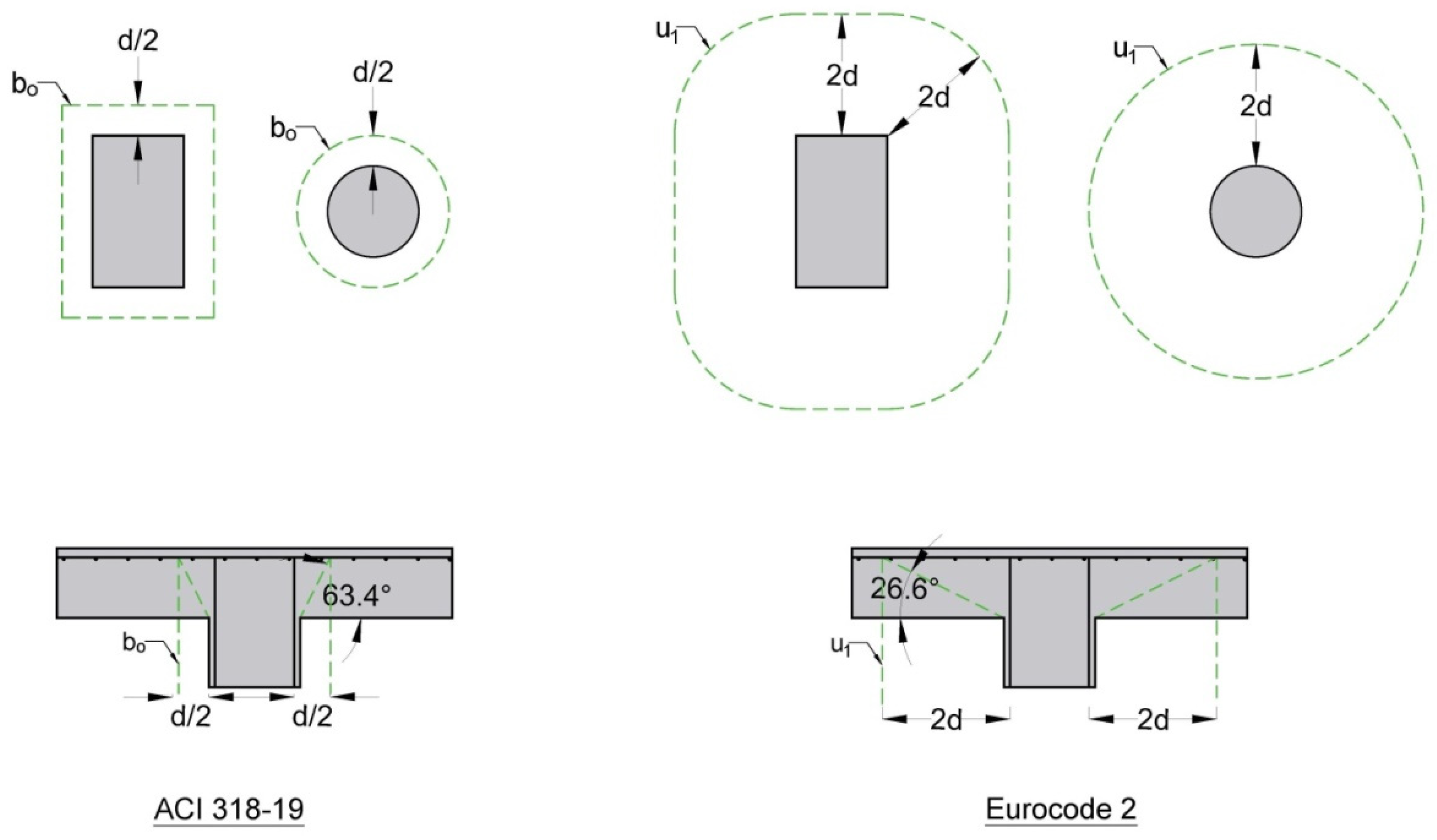
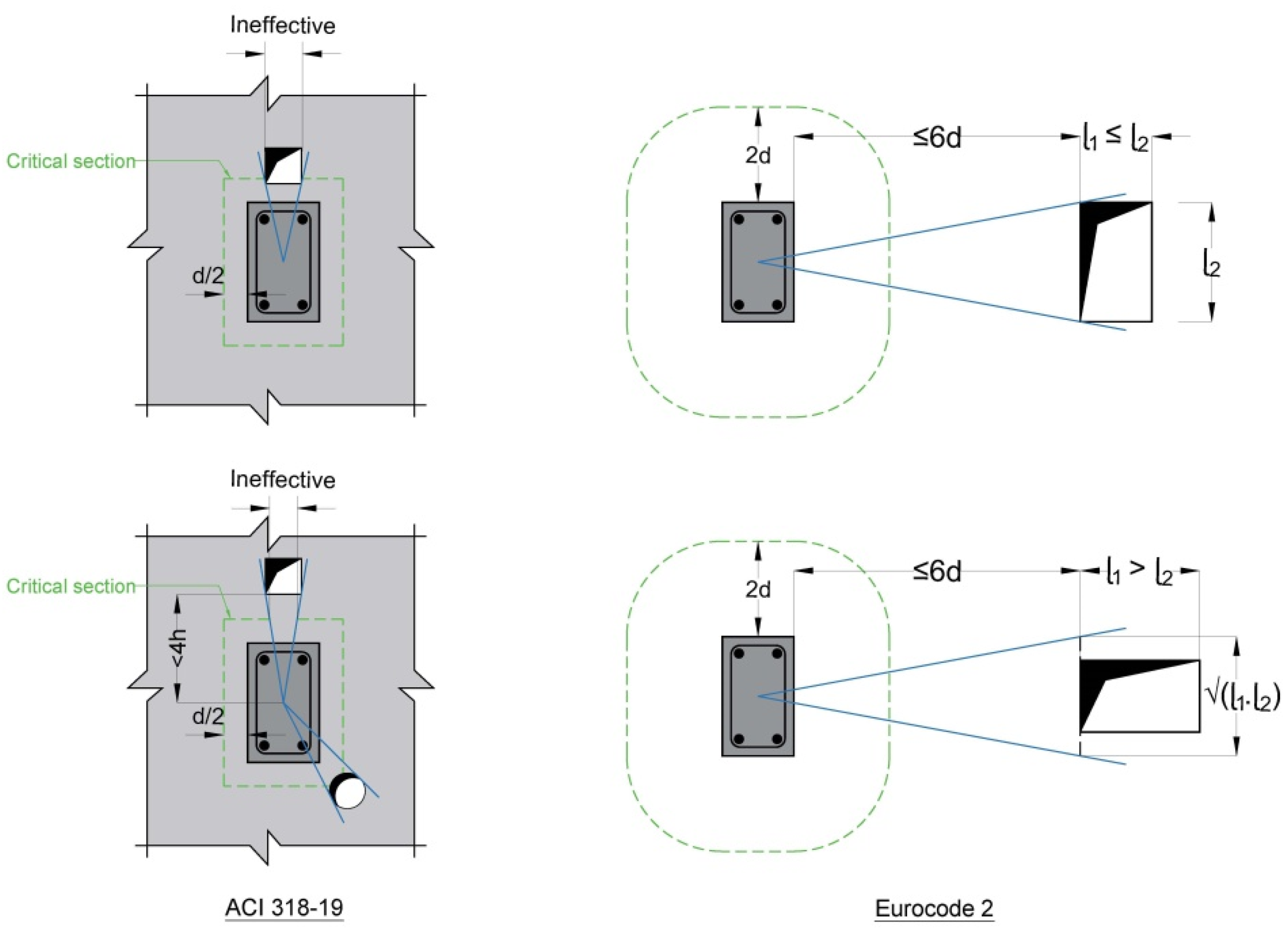
5. American and European Standards for the Punching Shear Resistance of Concrete Slabs

As previously stated, the international building codes adopted in this study are different in their determination of the concept and the shape of the punching shear region and the failure angle of slabs. Additionally, a code’s treatment of a column’s rectangularity, opening, and punching shear section placement may differ from another code’s [40].
The American code ACI 318-19 [28], mentioned in Section 22.6.5.2, determines the two-way shear resistance of solid RC flat slabs without shear reinforcement ( V c ) by checking the shear stress in the basic control shear section, which is situated ( 0.5 d ) away from the column’s perimeter (see Figure 1), where the smallest of the three Equations (19)–(21) must be selected, and that determines the V c .
V c = 0.33   ·   λ s   · λ   ·   f c   ·   b o   · d
V c = 0.083   · 2 + 4 β ·   λ s   · λ   ·   f c   ·   b o   · d
V c = 0.083   · 2 + α s   ·   d b o ·   λ s   ·   λ   ·   f c   ·   b o   · d
λ s = 2 1 + d 10         1.0
where V c —the concrete’s nominal shear resistance, N; λ s —the size effect modification factor; λ —the modification factor (=1.0 for normal-weight concrete), which reflects the decreased mechanical properties of light-weight concrete; f c —the concrete’s specified compressive strength, MPa; β —the rectangularity factor, which can be expressed as the reaction area, concentrated load, or the column’s ratio of the long to short side; and α s —a constant that is equal to 40 for inner columns, 30 for edge columns, and 20 for corner columns, depending on where the column is located.
The European code Eurocode 2 [29], mentioned in Section 6.4, calculates the solid RC flat slabs’ resistance to punching shear without shear reinforcement along the control section ( V R d , c ) at ( 2 d ) from the column’s face using the following expressions (see Figure 1):
V R d , c = 0.18 γ c   · k   ·   100   ·   ρ l   ·   f c k 3 ·   u 1   · d               V m i n
V m i n = 0.035   ·   k 3   ·   f c k   ·   u 1   · d
k = 1 + 200 d       2.0                                                                                                         d   i n   m m
ρ l = ρ l y ·   ρ l z       0.02    
where V R d , c —the design punching shear resistance, considering a slab with no punching shear reinforcement throughout the control section, N; γ c —the partial factor of safety for the concrete (=1.5); f c k —the concrete’s characteristic 28-day compressive cylinder strength, MPa; k —the size effect coefficient; ρ l —the longitudinal reinforcement ratio; and ρ l y , ρ l z —the critical section’s effective flexural reinforcement ratio in the ( y ) and ( z ) directions, respectively.
It is important to note that the ACI 318-19 [28] does not consider how flexural reinforcement affects the slab’s resistance to punching shear. Although the impact of flexural reinforcement is considered by the Eurocode 2 [29] using the value ( ρ l ), unlike the ACI 318-19, the Eurocode 2 disregards the impact of column rectangularity ( β ) on two-way shear resistance.

6. Adopted Treatments for Critical Openings in Concrete Slabs

Both international codes of practice share a similar approach when it comes to considering the impact of an opening in a RC flat slab near a column or loaded area on its shear resistance. The opening’s distance from the loaded area’s boundary is the main distinction between these codes.
According to Section 22.6.4.3 of the ACI 318-19 [28], if the distance between an opening and a reaction area or concentrated load is less than four times the slab’s thickness, the control shear perimeter ( b o ) may need to be reduced. This may be accomplished by disregarding the portion of the perimeter that is bounded by the projection lines that come from the reaction area, concentrated load, or column’s centroid, and are tangent to the opening’s borders, as shown in Figure 8.
If the column is close to an opening and the gap between the column’s boundary and the opening’s perimeter is not greater than six times the slab’s effective depth, then Section 6.4.2 of the Eurocode 2 [29] suggests certain rules for considering the influence of the opening on the punching shear resistance of the RC flat slab. It is advised to take into account the ineffectiveness of a portion of the control perimeter, which is delimited by two lines drawn from the loaded area’s center and its tangent to the opening’s outline. This part should be deducted from the basic control shear perimeter ( u 1 ), as depicted in Figure 8.
The Eurocode 2 provides more detailed guidelines for rectangular openings, particularly when the opening’s dimension in the radial direction ( l 1 ) exceeds its dimension in the transversal direction ( l 2 ). In such cases, the Eurocode 2 specifies that the dimension ( l 2 ) should be replaced with the new dimension ( l 1 · l 2 ), unlike the ACI 318-19.

7. Outcomes of This Study

7.1. Experimental Results and Discussion

During loading, the cracks’ initiation and propagation were carefully investigated on the freshly painted surfaces of the tested slabs. At every successive load stage, routine visual inspections were used to closely monitor the development of cracks on the surface of the concrete. Typically, the column stub or opening’s edges were usually where the first crack appeared. The cracking progress on the extreme bottom surface (tension), and then the top surface (compression), was reported when the bubbled slab was loaded. After the slab collapsed, the perimeter and area of the punched zone, as well as the punching angle, were recorded. The load imposed, steel strains, concrete strains, and deflection readings were taken immediately after each new loading level. Additional information on each of these measurements may be found in [48,49].
Table 2 displays our findings for the initial cracking and failure loads of the tested slabs. It is evident from the table that the use of plastic spheres that are hollow and the formation of an opening close to the loaded column stub had a major influence on the initial cracking load. In comparison to a solid slab (S0), the biaxial voided slab without any opening (B0) showed a reduction of 20% in its first cracking load. It has been observed that creating an opening close to the column in biaxial hollow slabs has a more significant influence on reducing its cracking load, compared to introducing hollow plastic spheres into specific regions. In the first group of specimens, bubbles were found all over the area except for the zone beneath the column stub. Depending on the dimensions, position, and separation of the opening from the column stub edge, the degree of the first cracking load reduction varied from 40% to 70%. For the same reasons, the first cracking load in specimens from the second group—where the bubbles were placed outside the section situated (2d) from the stub of the column—was reduced by 10 to 50%.
Compared to the solid control slab (S0), the punching shear resistance of the bubbled slab without openings (B0) was 37% less due to the loss of a significant portion of its failure surface, as the cracks reach the section with voids and/or openings. In the meantime, the punching shear strength decreased, ranging from 37 to 53% for slabs from the second group and from 53 to 66% for specimens from the first group due to the negative impact of the created openings combined with the presence of hollow plastic spheres in various slab regions.
After eliminating the areas of the bubbles that intersected with the corresponding control perimeter and the area of that portion of the perimeter which was enclosed by the projection planes that ran from the center of the column stub and the tangent to the boundaries of the opening, the area of the critical shear section, as defined by the ACI 318-19 and Eurocode 2, at sections situated ( 0.5 d ) and ( 2 d ), respectively, from the column’s stub perimeter, was determined.
Let us assess the net area factor ( Ω ) for sections situated ( 0.5 d ) and ( 2 d ) from the column face. This factor indicates the ratio of the critical section’s decreased area to the original shear perimeter’s area, as per the ACI 318-19 and Eurocode 2, respectively. Table 3 demonstrates that the variation of the net area factor ( Ω ) did not correspond to the punching shear resistance of the various experimental voided slabs. Unfortunately, even after subtracting the cross-sectional area of the voiding formers that overlapped the critical shear perimeters (i.e., decreasing the section punching area), the results calculated using these two design codes continued to be inaccurate. This was especially true for the bubbled slabs in the second group, where the voiding formers were outside of and did not overlap the critical sections that these codes specified. Accordingly, the overestimation obtained in calculating their shear capacity may be as high as 53%. This argument indicates that the adopted methodology for predicting the punching shear resistance based on the areas of the critical sections calculated according to the aforementioned international codes may lead to erroneous results that do not guarantee the accurate shear resistance of voided slabs.

7.2. Analytical Results and Discussion

In this section, a verification of the predicted shear capacity for all tested specimens was conducted, using in its calculations the experimental data for the slab dimensions, voiding formers’ dimensions, reinforcement ratio, and the concrete compressive strength. All computations were performed using real material properties and mathematical expressions for unfactored strengths. The concrete’s partial safety factor ( γ c ) was set equal to 1.0. Also, all experimental slabs in this study were cast using normal-weight concrete, i.e., (λ) is unity.
The ACI 318-19- and Eurocode 2-suggested methods are used to evaluate the experimental and estimated punching shear resistance, as shown in Table 4 and Table 5. The shear perimeters of a solid slab with the same depth to its cross-section and the bubbled slabs were the same, based on the first approach (i.e., voids are ignored). In contrast, the second approach considers the area of the web in addition to the influence of the concrete flange in the compression zone of the cross-section (i.e., voids are taken into consideration). Additionally, using the reduced-volume concept as a basis, the slabs’ punching shear capabilities were calculated using the suggested expressions for the effective shear perimeter: Equations (16) and (17).
It is important to note that the experimental punching shear resistance was exceeded by 28 to 86% and 23 to 75%, respectively, by the predicted punching shear capacity for tested bubbled slabs when voids were not taken into account, as per the ACI 318-19 and Eurocode 2.
As can be seen from Table 4 and Table 5, when the strength was calculated using these codes and taking into account the hollow plastic spheres distributed over all regions of the slab (i.e., specimens of the first group), the previously stated codes underestimated the punching shear resistance by 32 to 51% and 16 to 38%, respectively. However, when the strength was assessed using the same codes and when the area beyond the critical section ( 2 d ) from the column stub’s perimeter is where the voiding formers were embedded (i.e., specimens of the second group), the adopted procedures overestimated the punching shear strength by 28 to 34% and 23 to 27%, respectively.
It is important to notice from these data that, as the plastic bubbles approach the punching shear zone, the discrepancy between the experimental and predicted punching shear resistances becomes increasingly substantial. Additionally, it has been shown that the trend character—that is, the underestimation or overestimation character—of the difference between the estimated values and the data experimentally collected is significantly influenced by the position of the voiding formers. As a result, the computed data lacked a specific trend character and the shear resistance, as a function of the critical shear perimeter of the biaxial hollow slabs, was not consistently determined. Unfortunately, even when the voids were taken into account (i.e., subtracted), the estimated values provided by the ACI 318-19 and Eurocode 2 practice standards may not provide a precise punching shear resistance of the biaxial hollow slabs.
Since the punching shear resistance of the RC biaxial voided slabs is not taken into account by the present codes, it is unclear how the provisions pertaining to reinforced concrete solid flat slabs should be applied to biaxial hollow slabs when the voiding formers are situated inside or overlap with the control shear perimeter. Furthermore, in the case of biaxial hollow slabs, these clauses might not apply if the voiding formers extend beyond the critical area. Consequently, the effective shear perimeter was proposed to be applied using the derived Equation (16), to the ACI 318-19, and Equation (17), to the Eurocode 2 design approach, to determine the shear capability of punching.
Accordingly, the punching shear strength, which was estimated based on the suggested reduced-volume concept, was compared to the experimental results. Table 4 and Table 5 clearly show that there was a good correlation between the experimental findings of all biaxial hollow slabs and their theoretical punching shear capacities, which were calculated using the suggested effective shear perimeters (Equations (16) and (17)). The greatest discrepancy was found to be less than 11%. Based on the ACI 318-19 and Eurocode 2 practice codes, respectively, their punching shear capabilities were found to differ by as little as 4.2 and 4.3% on average between the theoretical and actual values.
According to the methods of the two international codes and the methodology proposed in this work, Table 6 displays the average values of the estimated ( V e s t ), in relation to the experimental ( V e x p ), punching shear strengths together with their standard deviations ( σ ) and coefficients of variation (CV). It is noteworthy that the two approaches suggested by the ACI 318-19 and Eurocode 2 did not produce satisfactory correlations or consistency for the estimated findings for these tested slabs, whether the continuous section slab concept or the voided section slab concept was taken into consideration. As can be shown in Table 6, the tested slabs’ coefficients of variation for the equations suggested in this study do not exceed 0.057. In contrast to alternative approaches, the suggested approach provided the smallest coefficient of variation of all the other approaches that these codes have previously suggested. This fact demonstrates the validity of the proposed equations. To verify the reduced volume approach to predicting the punching shear strength of different types of biaxial voided slabs and to investigate the effectiveness of the suggested Equations (14) and (15) in calculating the effective shear perimeter, comparisons were carried out between the theoretical results, calculated according to the approach proposed in this paper; the theoretical results of the approaches proposed by Held and Pfefer [11] and Valivonis et al. [21]; and the test outputs from the experimental work carried out by those authors.
Table 7 shows that the estimated punching shear capacities, calculated based on the methodology suggested by Held and Pfefer [11] for tested biaxial hollow slabs with plastic balls measuring 180 or 360 mm in diameter, were higher than the experimental punching resistances by 52 to 72%. Meanwhile, the results of the theoretical analysis using the aforementioned codes along with the approach proposed in this paper for the effective shear perimeter showed an appropriate range of correlation with the experimental data on the punching shear strength, where the range of discrepancy varied between 1 and 12% and 5 and 22% based on the practice codes for the ACI 318-19 and Eurocode 2, respectively.
Table 8 demonstrates that the difference between the experimental and estimated shear capacity, based on the effective shear perimeter equation proposed by Valivonis et al. [21], ranged between 2 and 8% using, respectively, the ACI 318-19 and Eurocode 2 calculation methods for tested biaxial voided slabs with plastic units of (350 × 350 × 180) mm dimensions. The effective shear perimeter equations provided in this study yielded a punching resistance that differed by 21 and 29%, respectively, between our experimental and theoretical findings.
It should be noted that the analysis and estimations were performed using a small sample of investigated specimens. The punching shear capacity of biaxial bubbled slabs has not been extensively studied, based on an analysis of the existing literature. More testing on more specimens is required to definitively confirm the suggested methodology for determining the effective punching shear perimeter.

8. Conclusions

The influence of inserting hollow plastic spheres and making openings adjacent to loaded column stubs on the punching shear resistance of biaxial bubbled slabs is the main subject of this study.
  • This article presents novel equations, which demonstrate substantial agreement with experimental findings, for computing the effective punching shear perimeter based on a reduced-volume concept.
  • This article draws attention to the fact that, when voids are taken into account, the traditional approaches of the ACI 318-19 and Eurocode 2 design codes may overestimate or underestimate the punching shear capabilities of biaxial voided slabs. When the hollow plastic spheres were arranged throughout the entire specimen, with the exception of the area beneath the column, the estimated punching shear strength according to the ACI 318-19 was 32% to 51% less than what the tested value was; when the spheres were arranged outside the critical shear perimeter of (2d), the calculated punching shear resistance was 28% to 34% higher than the test value. According to the Eurocode 2, these values were found to be 16% to 38% lower than the test values for the first group and 23% to 27% higher than the test values for the second group.
  • Our suggested approach provides increased precision and consistency for estimating the shear capacity of biaxial voided slabs. It was found that the biggest differences observed between the test results and the calculated shear strength were below 8% and 11%, respectively, as per the ACI 318-19 and Eurocode 2 methodologies.
  • It is important to accurately account for the presence and location of voiding formers in these analysis calculations to ensure the accurate prediction of punching shear resistance. Given that the coefficient of variation of the proposed expressions for the slabs investigated in the current study is not greater than 0.057, our recommended treatment of the influence of voiding formers in biaxial hollow slabs on the slabs’ shear capacity was found to be quite reasonable.
  • The suggested approach had the lowest coefficient of variation when compared to other approaches that had previously been advised by the aforementioned practice codes. This fact demonstrates that our proposed approach is trustworthy.

Author Contributions

Conceptualization, N.O. and H.M.; methodology, N.O. and A.A.; software, H.M. and A.A.; validation, N.O., H.M. and G.W.; formal analysis, N.O. and H.M.; investigation, N.O. and H.M.; resources, A.A. and G.W.; data curation, N.O. and G.W.; writing—original draft preparation, N.O. and H.M.; writing—review and editing, A.A. and G.W.; visualization, N.O.; supervision, N.O. and A.A.; project administration, N.O. and G.W.; funding acquisition, N.O. and H.M. All authors have read and agreed to the published version of the manuscript.

Funding

This research received no external funding.

Data Availability Statement

Data are contained within the article.

Acknowledgments

The authors appreciate and gratefully thank the Structural Laboratory staff of the Department of Civil Engineering at the University of Baghdad, Iraq, for their support during the experimental part of this research. In addition, the authors are grateful to and thank the Consulting Engineering Bureau at the University of Baghdad (CEB-UOB) for their assistance in completing the material tests.

Conflicts of Interest

The authors declare no conflicts of interest.

References

  1. Midkiff, C.J. Plastic Voided Slab Systems: Applications and Design. Master’s Thesis, Kansas State University, Manhattan, KS, USA, 2013. [Google Scholar]
  2. Marais, C.C. Design Adjustment Factors and the Economical Application of Concrete Flat-Slabs with Internal Spherical Voids in South Africa. Master’s Dissertation, University of Pretoria, Hatfield, South Africa, 2008. Available online: http://hdl.handle.net/2263/27476 (accessed on 2 October 2023).
  3. Marais, C.C.; Robberts, J.M.; van Rensburg, B.W.J. Spherical void formers in concrete slabs. J. S. Afr. Inst. Civ. Eng. 2010, 52, 2–11. [Google Scholar]
  4. Khouzani, M.A.; Zeynalian, M.; Hashemi, M.; Mostofinejad, D.; Farahbod, F.; Shahadifar, M. A numerical study on flexural behavior of biaxial voided slabs containing steel cages. J. Build. Eng. 2021, 44, 103382. [Google Scholar] [CrossRef]
  5. Hai, L.V.; Hung, V.D.; Thi, T.M.; Nguyen-Thoi, T.; Phuoc, N.T. The Experimental Analysis of BubbleDecK Slab Using Modified Elliptical Balls. In Proceedings of the Thirteenth East Asia-Pacific Conference on Structural Engineering and Construction (EASEC-13), Sapporo, Japan, 11–13 September 2013. G-6-1. [Google Scholar]
  6. Churakov, A. Biaxial hollow slab with innovative types of voids. Constr. Unique Build. Struct. 2014, 21, 70–88. [Google Scholar]
  7. Adil, A.I.; Hejazi, F.; Rashid, R.S.M. Voided Biaxial Slabs—State of Art. IOP Conf. Ser. Earth Environ. Sci. 2019, 357, 012004. [Google Scholar] [CrossRef]
  8. Gamal, M.; Heiza, K.; Hekal, G.M.; Nabil, A. Voided Slabs As A New Construction Technology-A Review. In Proceedings of the International Conference on Advances in Structural and Geotechnical Engineering, ICASGE’23, Hurghada, Egypt, 6–9 March 2023; 22p. [Google Scholar]
  9. Nasvik, J. On the bubble: Placing concrete around plastic voids increase efficiency and reduces costs. Concr. Constr.-World Concr. 2011, 56, 20–22. [Google Scholar]
  10. Wesley, N. Viscoelastic Analysis of Biaxial Hollow Deck Balls. Int. J. Comput. Aided Eng. 2013, 23, 1103–1110. [Google Scholar]
  11. Schnellenbach-Held, M.; Pfeffer, K. Punching Behavior of Biaxial Hollow Slabs. Cem. Concr. Compos. 2002, 24, 551–556. [Google Scholar] [CrossRef]
  12. Broms, C.E. Elimination of flat plate punching failure mode. ACI Struct. J. 2000, 97, 94–101. [Google Scholar] [CrossRef]
  13. Hegger, J.; Ricker, M.; Sherif, A.G. Punching Strength of Reinforced Concrete Footings. ACI Struct. J. 2009, 106, 706–716. [Google Scholar]
  14. Siburg, C.; Ricker, M.; Hegger, J. Punching Shear Design of Footings: Critical Review of Different Code Provisions. Struct. Concr. 2014, 15, 497–508. [Google Scholar] [CrossRef]
  15. Bhagat, S.; Parikh, K.B. Parametric Study of R.C.C Voided and Solid Flat Plate Slab using SAP 2000. IOSR J. Mech. Civ. Eng. 2014, 11, 12–16. [Google Scholar] [CrossRef]
  16. Arslan, G.; Polat, Z. Contribution of Concrete to Shear Strength of RC Beams Failing in Shear. J. Civ. Eng. Manag. 2013, 19, 400–408. [Google Scholar] [CrossRef]
  17. Birkle, G.; Dilger, W.H. Shear Strength of Slabs with Double-Headed Shear Studs in Radial and Orthogonal Layouts. Int. Concr. Abstr. Portal 2009, 265, 499–510. [Google Scholar]
  18. Borges, L.L.J.; Melo, G.S.; Gomes, R.B. Punching shear of reinforced concrete flat plates with openings. ACI Struct. J. 2013, 110, 547–556. [Google Scholar] [CrossRef]
  19. Vainiṹnas, P.; Popovas, V.; Jarmolajev, A. Punching Shear Behaviour Analysis of RC Flat Floor Slab-to-Column Connection. J. Civ. Eng. Manag. 2002, 8, 77–82. [Google Scholar] [CrossRef]
  20. AL-Mohammadi, A.; AL-Bayati, A. Punching Shear Strength of Voided Slab: Literature Review and Evaluation of Design Codes. Wasit J. Eng. Sci. 2022, 10, 131–145. [Google Scholar] [CrossRef]
  21. Valivonis, J.; Šneideris, A.; Šalna, R.; Popov, V.; Daugevicius, M.; Jonaitis, B. Punching Strength of Biaxial Voided Slabs. ACI Struct. J. 2017, 114, 1373–1383. [Google Scholar] [CrossRef]
  22. Valivonis, J.; Skuturna, T.; Daugevičius, M.; Sneideris, A. Punching shear strength of reinforced concrete slabs with plastic void formers. Constr. Build. Mater. 2017, 145, 518–527. [Google Scholar] [CrossRef]
  23. Valivonis, J.; Jonaitis, B.; Zavalis, R.; Skuturna, T.; Šneideris, A. Flexural Capacity and Stiffness of Monolithic Biaxial Hollow Slabs. J. Civ. Eng. Manag. 2014, 20, 693–701. [Google Scholar] [CrossRef]
  24. Albrecht, C.; Albert, A.; Pfeffer, K.; Schnell, J. Design and Construction of Two-Way Spanning Reinforced Concrete Slabs with Flattened Rotationally Symmetrical Void Formers. Concr. Reinf. Concr. Constr. 2012, 107, 2–12. [Google Scholar]
  25. Han, S.W.; Lee, C.S. Evaluation of Punching Shear Strength of Voided Transfer Slabs. Mag. Concr. Res. 2014, 66, 1116–1128. [Google Scholar] [CrossRef]
  26. Sakin, S.T. Punching Shear in Voided Slab. Civ. Environ. Res. 2014, 6, 36–43. [Google Scholar]
  27. Oukaili, N.K.; Husain, L.F. Punching Shear Strength of BubbleDecks under Eccentric Loads. In Proceedings of the Second International Conference on Science, Engineering & Environment, Osaka, Japan, 21–23 November 2016; pp. 222–227. [Google Scholar]
  28. ACI Committee 318. Building Code Requirements for Structural Concrete (ACI 318–19) and Commentary (ACI 318R–19); American Concrete Institute: Farmington Hills, MI, USA, 2019; p. 623. [Google Scholar]
  29. EN 1992-1-1; Eurocode 2—Design of Concrete Structures—Part 1: General Rules and Rules for Buildings. European Committee for Standardization: Brussels, Belgium, 2004; p. 225.
  30. Shaaban, I.G.; Hosni, A.H.; Montaser, W.M.; El-Sayed, M.M. Effect of premature loading on punching resistance of reinforced concrete flat slabs. Case Stud. Constr. Mater. 2020, 12, e00320. [Google Scholar] [CrossRef]
  31. Chung, J.H.; Choi, H.K.; Lee, S.C.; Choi, C.S. Punching Shear Strength of Biaxial Hollow Slab with Donut Type Hollow Sphere. Key Eng. Mater. 2011, 452–453, 777–780. [Google Scholar] [CrossRef]
  32. Sagadevan, R.; Rao, B.N. Experimental and analytical investigation of punching shear capacity of biaxial voided slabs. Structures 2019, 20, 340–352. [Google Scholar] [CrossRef]
  33. Sagadevan, R.; Rao, B.N. Punching shear capacity of RC biaxial voided slab—prediction by critical shear crack theory. In Proceedings of the 12th Structural Engineering Convention (SEC 2022), NCDMM, MNIT, Jaipur, India, 19–22 December 2022; pp. 411–415. [Google Scholar] [CrossRef]
  34. Ibrahim, A.; Ismael, M.; Abdul Hussein, H. The Effect of Balls Shapes and Spacing on Structural Behaviour of Reinforced Concrete Bubbled Slabs. J. Eng. Sustain. Dev. 2019, 23, 56–65. [Google Scholar] [CrossRef]
  35. Oukaili, N.; Hussein, L. Experimental and Analytical Study on Punching Shear Strength of BubbleDecks. ACI Struct. J. 2020, 117, 17–31. [Google Scholar] [CrossRef]
  36. Gajewski, T.; Staszak, N.; Garbowski, T. Optimal Design of Bubble Deck Concrete Slabs: Serviceability Limit State. Materials 2023, 16, 4897. [Google Scholar] [CrossRef] [PubMed]
  37. Hognestad, E.; Elstner, R.C.; Hanson, J.A. Shear Strength of Reinforced Structural Lightweight Aggregate Concrete Slabs. ACI J. Proc. 1964, 61, 643–656. [Google Scholar]
  38. Broms, C.E. Punching of Flat Plates—A Question of Concrete Properties in Biaxial Compression and Size Effect. ACI Struct. J. 1990, 87, 292–304. [Google Scholar] [CrossRef]
  39. El-Salakawy, E.F.; Polak, M.A.; Soliman, M.H. Reinforced Concrete Slab-Column Edge Connections with Openings. ACI Struct. J. 1999, 96, 79–87. [Google Scholar]
  40. Teng, S.; Cheong, H.K.; Kuang, K.L.; Geng, J.Z. Punching Shear Strength of Slabs with Openings and Supported on Rectangular Columns. ACI Struct. J. 2004, 101, 678–687. [Google Scholar]
  41. Oukaili, N.K.A.; Salman, T.S. Punching Shear Strength of Reinforced Concrete Flat Plates with Openings. J. Eng. Univ. Baghdad 2014, 20, 1–20. [Google Scholar] [CrossRef]
  42. Gomes, R.B.; Andrade, M.A.S. Punching in Reinforced Concrete Flat Slabs with Openings. Developments in Computer Aided Design and Modelling for Structural Engineering; Civil-Comp Press: Edinburgh, UK, 1995; pp. 185–193. [Google Scholar]
  43. Regan, P.E. Shear Reinforcement of Flat Slabs; TRITA-BKN Bulletin 57. In International Workshop Punching Shear Capacity of RC Slabs; Royal Institute of Technology: Stockholm, Sweden, 2000; pp. 97–107. [Google Scholar]
  44. Kuang, L.; Teng, S. Punching Shear Strength of Slabs with Openings and Supported on Rectangular Columns; School of Civil Engineering, Nanyang Technological University: Singapore, 2001; p. 298. [Google Scholar]
  45. El-Shafiey, T.F.; Atta, A.M.; Hassan, A.; Elnasharty, M. Effect of Opening Shape, Size and Location on the Punching Shear Behaviour of RC Flat Slabs. Structures 2022, 44, 1138–1151. [Google Scholar] [CrossRef]
  46. Al-Rousan, R.Z.; Alnemrawi, B.R. Punching Shear Code Provisions Examination Against the Creation of an Opening in Existed RC Flat Slab of Various Sizes and Locations. Structures 2023, 49, 875–888. [Google Scholar] [CrossRef]
  47. Hammood, H.J.; Esfandiari, J.; Movahednia, M.; Roudsari, M.T. Openings Effects on the Structural Behavior of Interior Voided Slab-Column Connections: An Experimental Study. Case Stud. Constr. Mater. 2023, 18, e01998. [Google Scholar] [CrossRef]
  48. Oukaili, N.; Merie, H. Reduced Area Approach for Predicting Punching Shear Resistance of Biaxial Hollow Slabs with Openings. Results Eng. 2023, 19, 101261. [Google Scholar] [CrossRef]
  49. Oukaili, N.; Merie, H. CFRP Strengthening Efficiency on Enhancement Punching Shear Resistance of RC Bubbled Slabs with Openings. Case Stud. Constr. Mater. 2021, 15, e00641. [Google Scholar] [CrossRef]
  50. ASTM C39/C39M-21; Standard Test Method for Compressive Strength of Cylindrical Concrete Specimens. ASTM International: West Conshohocken, PA, USA, 2021.
  51. ASTM 615/A615M-15; Standard Specifications for Deformed and Plain Carbon-Steel Bars for Concrete Reinforcement. ASTM International: West Conshohocken, PA, USA, 2015.
  52. Braestrup, M.W.; Nielsen, M.P.; Jensen, B.C.; Bach, F. Axisymmetric Punching and Reinforced Concrete; Report No. R-75; Structural Research Laboratory, Technical University of Denmark: Kongens Lyngby, Denmark, 1976; p. 33. [Google Scholar]
  53. Salim, W.; Sebastian, W.M. Plasticity Model for Predicting Punching Shear Strengths of Reinforced Concrete Slabs. ACI Struct. J. 2002, 99, 827–835. [Google Scholar]
  54. Santos, J.B.D.; de Sales Melo, G.; Ruiz, M.F. Punching performance of flat slabs with openings accounting for the influence of moment transfer and shear reinforcement. Eng. Struct. 2024, 303, 117461. [Google Scholar] [CrossRef]
  55. Kinnunen, S.; Nylander, H. Punching of Concrete Slabs without Shear Reinforcement. Trans. R. Inst. Technol. 1960, 158, 112. [Google Scholar]
  56. Al-Bayati, A.F.; Lau, T.L.; Clark, L.A. Concentric Punching Shear of Waffle Slab. ACI Struct. J. 2015, 112, 533–542. [Google Scholar] [CrossRef]
Figure 1. Punching shear perimeters suggested by ACI 318-19 and European practice codes.
Buildings 14 00676 g001
Figure 2. Experimental specimens—layout and dimensions.
Buildings 14 00676 g002
Figure 3. Cross-sectional configuration and reinforcement details of tested slabs.
Buildings 14 00676 g003
Figure 4. Cross-section in biaxial voided slabs with hollow spherical and elliptical balls [5].
Buildings 14 00676 g004
Figure 5. Crack pattern at failure of experimental specimens.
Buildings 14 00676 g005
Figure 6. Stress distribution in biaxial hollow slabs at their failure stage, according to ANSYS–Version (14.0) software.
Buildings 14 00676 g006
Figure 7. Intersection of the control shear perimeter and hollow plastic spheres. (a) Less than half of the volume of the spheres is inside the critical section. (b) More than half of the volume of the spheres is inside the critical section.
Buildings 14 00676 g007
Figure 8. Effective critical perimeter, as defined by two international codes, for slabs with openings.
Buildings 14 00676 g008
Table 1. Details of bubbles’ distribution and opening locations in experimental specimens.
Specimen DesignationDistribution Pattern of BubblesEdge Length of Square Opening (mm)Position of Opening in Relation to the ColumnColumn’s Distance from the Opening (mm)
GroupS0----
B0across all regions---
IB10CIacross all regions300at corner0
B10FI300in front0
B12FI300in front200
B20FI450in front0
IIB10COoutside the critical section300at corner0
B10FO300in front0
B12FO300in front200
B20FO450in front0
Table 2. Cracking load and punching shear strength of experimental slabs.
Specimen Compressive   Strength   f c
(MPa)
Cracking   Load   P c r
(kN)
P c r P c r ( S 0 )
(%)
P c r P c r ( B 0 )
(%)
Punching   Shear   Strength   V e x p
(kN)
V e x p V e x p   ( S 0 )
(%)
S026.6200100-760100
B025.51608010048063
B10CI26.31005062.534045
B10FI26.3804050.030039
B12FI25.71206075.036047
B20FI27.4603037.526034
B10CO28.71407087.546061
B10FO28.21206075.041054
B12FO29.518090112.548063
B20FO27.21005062.536047
Table 3. Experimental variations in punching shear resistance and the reduced area of the critical sections according to the adopted international standards.
Specimen Shear   Strength   V e x p (kN) V e x p V e x p   ( S 0 )
(%)
V e x p   ( g r o u p I I ) V e x p   ( g r o u p I )
(%)
Ratio   of   Net   Reduced   Area   to   Original   Area   of   Critical   Sec tions ,   Ω
(%)
ACI 318-19Eurocode 2
GroupS0760100-100100
B048063-6569
IB10CI34045-5861
B10FI30039-5358
B12FI36047-6064
B20FI26034-5053
IIB10CO46061135.3100100
B10FO41054136.7100100
B12FO48063133.3100100
B20FO36047138.5100100
Table 4. Punching shear capacity as calculated by the ACI 318-19, using the reduced-volume concept (Equation (16)).
Specimens V e x p (kN)Perimeter Used According to ACI 318-19Perimeter Used According to the Reduced-Volume Concept, Equation (16)
Voids Are Not ConsideredVoids Are Considered
b o (mm) V c (kN) V e x p V c V e x p (%) b o (mm) V c (kN) V e x p V c V e x p (%) b o (mm) V c (kN) V e x p V c V e x p (%)
S07602000681102000681+102000681+10
B04802000667−39704235+511327442+8
B10CI3401660562−65528179+471025347−2
B10FI3001500508−69528179+40869294+2
B12FI3601770592−64666222+381148384−7
B20FI2601400484−86508176+32775268−3
B10CO4601660587−281660587−281283454+1
B10FO4101500526−281500526−281123393+4
B12FO4801770634−321770634−321400502−5
B20FO3601400482−341400482−34985339+6
Table 5. Punching shear capacity as calculated by Eurocode 2, using the reduced-volume concept (Equation (17)).
Specimens V e x p (kN)Perimeter Used According to Eurocode 2Perimeter Used According to the Reduced-Volume Concept, Equation (17)
Voids Are Not ConsideredVoids Are Considered
u 1 (mm) V R d , c (kN) V e x p V R d , c V e x p (%) u 1 (mm) V R d , c (kN) V e x p V R d , c V e x p (%) u 1 (mm) V R d , c (kN) V e x p V R d , c V e x p (%)
S07603712680+113712680+113712680+11
B04803712671−401648297+382367428+11
B10CI3403012550−621542282+171806330+3
B10FI3002784508−691236226+251544282+6
B12FI3603212582−621290234+3519853600
B20FI2602462456−751182219+161387257+1
B10CO4603012566−233012566−232519474−3
B10FO4102784520−272784520−272291428−4
B12FO4803212609−273212609−272728518−8
B20FO3602462455−262462455−261997369−3
Table 6. Statistical evaluation of the theoretical punching shear strength of tested biaxial hollow slabs according to different methods.
StandardTreatment Concept Average   of   ( V e s t / V e x p ) Standard   of   Deviation   ( σ )Coefficient of Variation (CV)
ACI 318-19Continuous section concept1.4960.2180.146
Voided section concept0.9030.3850.427
Proposed reduced-volume concept 0.9950.050.05
Eurocode 2Continuous section concept1.4570.2120.145
Voided section concept0.9690.2830.292
Proposed reduced-volume concept 0.9970.0570.057
Table 7. Experimental and theoretical punching shear capacities, determined based on the perimeters calculated according to the reduced-volume concept for biaxial hollow slabs tested by Held and Pfefer [11].
Slab V e x p (kN)Perimeter According to Held and Pfefer MethodologyPerimeter According to Reduced-Volume Concept, Equation (16) or Equation (17)
ACI 318-19Eurocode 2
V e s t (kN) V e x p V e s t V e x p (%) V e s t (kN) V e x p V e s t V e x p (%) V e s t (kN) V e x p V e s t V e x p (%)
D1-24520840−62534−3431+17
D2-24580945−63571+2450+22
D3-24525893−70547-4438+17
D4-459351503−61888+51009−8
D5-459901701−721005−11095−11
D6-4511801795−521039121120+5
Average of ( V e s t / V e x p )1.632 0.983 0.929
Standard of deviation ( σ )0.071 0.060 0.139
Coefficient of variation (CV)0.044 0.061 0.150
Table 8. Experimental and analytical punching shear capabilities, determined based on the perimeters calculated according to the reduced-volume concept for biaxial voided slabs tested by Valivonis et al. [21].
Slab V e x p (kN)Perimeter According to Valivonis et al. MethodologyPerimeter According to Reduced-Volume Concept, Equation (16) or Equation (17)
ACI 318-19Eurocode 2
V e s t (kN) V e x p V e s t V e x p (%) V e s t (kN) V e x p V e s t V e x p (%) V e s t (kN) V e x p V e s t V e x p (%)
BP1-1773838−8810−57700
BP1-2801835−48010762+5
BP2-1443417+6491−11351+21
BP2-2451436+3580−294530
BP3-1630617+2697−11638−1
BP3-2658626+5717−96570
Average of ( V e s t / V e x p )0.994 1.106 0.959
Standard of deviation ( σ )0.057 0.097 0.085
Coefficient of variation (CV)0.057 0.088 0.088
Disclaimer/Publisher’s Note: The statements, opinions and data contained in all publications are solely those of the individual author(s) and contributor(s) and not of MDPI and/or the editor(s). MDPI and/or the editor(s) disclaim responsibility for any injury to people or property resulting from any ideas, methods, instructions or products referred to in the content.

