Article

Experimental Analysis of Mechanical Behavior of Timber-Concrete Composite Beams with Different Connecting Systems

by
Radovan Cvetković
1,*,
Slobodan Ranković
1,
Tatjana Kočetov Mišulić
2 and
Danijel Kukaras
2
1
Faculty of Civil Engineering and Architecture, University of Niš, 18000 Niš, Serbia
2
Faculty of Technical Sciences, University of Novi Sad, 21000 Novi Sad, Serbia
*
Author to whom correspondence should be addressed.
Buildings 2024, 14(1), 79; https://doi.org/10.3390/buildings14010079
Submission received: 29 October 2023 / Revised: 15 December 2023 / Accepted: 25 December 2023 / Published: 27 December 2023
(This article belongs to the Special Issue Advances in Composite Construction in Civil Engineering)

Abstract

:
Timber-concrete composite structures are innovative structural systems which have become the subject of extensive research and practical usage, primarily due to their attractive mechanical properties. This article deals with the experimental procedure and the analysis of the mechanical behavior of two different series of timber-concrete composite beams with the same span and geometry of cross-sections. In the first BF-series, the screws were used as a connecting system between the timber and concrete parts, whereas in the BN-series the combination of notches and screws, as a more complex system, was used for the same purpose. Both series were exposed to loading up to a failure by means of the standard four-point bending test. The mechanical behavior of the BF and BN-series beams was analyzed by a comparative analysis referring to: the correlation of the failure loading and the deflection, mechanisms of failure, the strain development across the height of mid-span’s and support’s cross-sections, the horizontal displacement in the timber-concrete interlayer at the support zones, the value of shear stresses and the calculated values of the effective bending stiffness of the beams. The differences in bearing capacity between both series of beams were negligible (about 5%), the effective bending stiffness of BF beams is lower for 32.86% compared to the BN-series and the average value of deflections in BF-series beams is twice as high than in the BN-series. The BN-series beams showed better mechanical behavior in aspects of development of shear stresses in support zones, exhibiting lower shear stress values with an average of 40%.

1. Introduction

Timber-concrete composite (TCC) structures are innovative structural systems which have become the subject of research and practical usage in developed countries (Scandinavian countries, Australia, and the USA), primarily due to their attractive mechanical properties [1,2]. In recent years, this type of structural system with numerous varieties is present worldwide in structural engineering, mostly while reconstructing floor structures in old buildings protected by cultural heritage law, Figure 1, but also as an effective system in the design of large-span floor structures in new buildings and TC bridges. This is due to the fact that timber has relatively high tension strength, and through its coupling with concrete which has a high level of compression strength, optimal usage of the mechanical properties of these two materials is achieved. Structural elements created in this way are of a lower weight compared to classical concrete elements, thus leading to a reduced total weight of built facilities and consequently, better performance of buildings under seismic loads and reduced workload related to design and shaping of the foundation. Compared to classical timber elements, the increased stiffness, reduced deflections, improved soundproofing and reduced sensitivity to vibrations are advantages of the TCC composite action. Besides, a concrete slab positioned over timber beams such as in bridge structures (that are protected from the sun and other negative weather effects such as rain, snow, ice, etc.) and in floor structures (protected from fires) contributes to the durability of these structures and represents the additional advantage of TCC structures. Generally, TCC structural elements nowadays can be found in new residential buildings and offices, industrial and sports facilities, bridge structures as well as in reconstructing and refurbishment of old building especially when a minimum modification of the structural system is required, thus preserving their authenticity [3,4].

Previous Experimental Research

In recent years, a certain number of authors have achieved and presented the results of their research work related to the mechanical performance of TCC structures exposed to static loading up to a failure. Varying the key components of load bearing systems (timber, concrete, and connecting systems) in different experimental campaigns, their research significantly contributed to the estimation of the achieved degree of composite action by different coupling means in TCC, defining the load at the limit state, as well as the mechanism of failure depending on a number of parameters. In order to get comparable results and to enlarge the data base, experimental analyses were conducted in accordance with the standards for the mechanical properties of used constitutive materials, fasteners or defined connecting systems, as well as according to prescribed loading protocols. The common method for defining the value of the slip modulus of a chosen connecting system [5] is the so called push-out test which is also necessary for the estimation of stiffness of the joint created by the timber and concrete part of the coupled cross section. The research most relevant to this is the following:
Clouston [6] examined, using the four-point bending test, the composite system created by glued-laminated (GL) timber and concrete (10 m span) with a continual steel mesh inserted in three rows along the whole length of the system used as a connecting system.
Ceccotti [7,8] tested a composite system which consists of two GL beams (with cross-section dimensions b/h = 125/500 mm) and a concrete slab (with cross-section dimensions bp/dp = 100/1400 mm), with a span of 6 m. A fastener connecting system, made of reinforcement bars with a diameter of 18 mm, was installed into previously drilled holes positioned with a spacing of 150–450 mm along the joint of the timber and concrete. The holes were filled with epoxy resin. Prior to the static test, the beams were exposed to constant long-term outdoor loading for 5 years, during which their performance was monitored. The failure occurred under a load of 2 P = 500 kN. The measured deflection in the mid-span was 33.2 mm and the interlayer timber-concrete slip in the support zone was 2.47 mm. The brittle failure due to excessive tension strength of the timber part of the tested TCC structure was caused by a 2.44 times higher value of the load in comparison to the original design. The degree of the composite action was reported in the range of 87–93%. The results of the experiment were compared with results obtained by the “γ”-procedure [9], in which the slip modulus values of fasteners Ko4, Ko6 and Ko8 defined by push-out test were used in the calculation and good matching of results was achieved.
Gutkowski [10,11,12,13,14,15] tested TCC beams with notches in the timber and screws in order to increase the friction in the interlayer of the two materials. A common four-point bending test up to failure was carried out on a model with a span of 3.51 m. The degree of composite action was reported in the range of 54.9–77%; the failure was caused by bending in the timber and by low mechanical behavior of notches caused by the concrete segregation.
Lukaszewska [16,17,18], examined 5 beams, 4.8 m long and with the triple “T” cross-section formed by GL beams over which a prefabricated concrete slab was connected by SST + S type connectors positioned at different inter-distances. The connection was completed with steel anchors previously built in the concrete slab and specially shaped U profiles, whose upper part was built in the slab before its prefabrication, while the lower part was connected to the upper part of the timber beams by nails.
According to the results from the two series of beams designed in the described way, but with two different systems of coupling, the authors concluded that the beams with screws and steel anchors had degree of composite actions of 60%, while the specimens where timber beams were connected to pre-fabricated concrete slab by nails, it was only 30%. In order to increase the efficiency of coupling, the concluding suggestion was to combine screws and steel anchors together with notches in the timber part of the composite cross-section, so that the shear force in the timber-concrete interlayer could be reduced.
Yeoh [19,20], obtained significant results while analyzing the performance of 11 beams with spans of 8.0 m and 10.0 m, coupled by screws and notches of particular geometry in timber (5 beams) and single-sided tooth metal plate with perforated holes at the top (6 beams), using the common four-point bending test. Six beams were designed for the common dead load of 3.0 kN/m2 (according to regulations), and the remaining five beams were designed for an underestimated load of 1.0 kN/m2. The achieved degree of composite action was in the range of 87.60–99.23%. Failure of the well-designed specimen-beams occurred when the loading was 2.29–2.91 times higher than the calculated one, while in the second case, that value was 1.17–2.31. The authors verified the results of experiments by calculation analysis based on a number of follow-up studies on connecting systems and the “γ“-procedure.
Dias et al. [21], within the framework of COST FP1402 Action WG4: Hybrid Structures summarized European research and practices in the field of TCC. The state-of-the-art given in this report reflects parts of the research and the discussions among experts, covering all relevant issues: material and loads as input values, different types of connection and their properties, methods of testing, available codes and guidelines, methods of evaluation and phenomena occurring in the analysis of short and long-term loading, design examples and methods for the design. This document directly influenced and contributed to preparation of FprCEN/TS 19103-Structural design of TCC structures.
Shan et al. [22] showed short-term bending tests conducted on glue-laminated bamboo (glubam) and concrete composite (BCC) beams. Four types of connection details were designed and tested: continuous steel mesh, screw connector, notch connector and pre-tightening notched connector. Experimental variables included length and numbers of connectors. Four-point bending tests to failure were performed on nine full-scale 8.0 m long BCC beams. All BCC beams with different connections showed satisfactory performance under short-term loading conditions. The 200 mm long notch connection is recommended for composite beams for higher load carrying capacity and composite action. The semi-prefabricated composite beam using the pre-tightening notched connector shows similar bending capacity compared with the corresponding BCC cast in situ.
In Yiang et al. [23], six groups of push-out tests were performed to investigate the shear performance of notched connectors for timber-concrete composite beams, with consideration of the varying concrete types, the shear length of the timber, and whether the notch was reinforced. From the test results, the notched connectors that corresponded to the shear failure of concrete or timber had low shear capacity and poor ductility. Notched connectors that simultaneously failed at the concrete slab (via shear force), as well as at the lag screw reinforcement point during bending exhibited the greatest shear capacity. Screw fasteners in the notch were shown to improve the strength, ductility, and post-peak behavior of the notched connectors.
Hu et al. [24], discussed behavior of a timber–lightweight–concrete (TLC) composite beam connected with a ductile connector made of a stainless–steel bolt anchored with nuts at both ends. Experimental testing was implemented to investigate the TLC composite specimen push–out results and bending performance. The shear specimen push–out results show that shear–slip curves exhibit good ductility and that their failure can be attributed to bolt buckling accompanied by lightweight concrete cracking. The effects of different bolt diameters on the strengthening effect of the TLC composite beams were studied through bending tests on ten TLC composite beams and two contrast (pure timber) beams. The results demonstrate that the TLC composite beams and contrast timber beams break on the timber fiber at the lowest edge of the TLC composite beam, and the failure mode is attributed to bending failure, while the bolt connectors and lightweight concrete have no obvious breakage. Moreover, the ductile bolt connectors show good connection performance until the TLC composite beams fail. The ultimate bearing capacities of the TLC composite beams increase 2.03–3.5 times compared to those of the contrast beams, while the mid-span maximum deformation decrease nearly doubled.
Mirdad et al. [25], present an analytical approach for designing a TCC floor system based on certain connection models with an aim to predict connection properties from basic connection component properties such as embedment and withdrawal strength/stiffness of the connector, without tests. The analytical approach leads to the calculation of effective bending stiffness, forces in the connectors, and extreme stresses in concrete and timber of the TCC system, and can be used in design to evaluate allowable floor spans under specific design loads and criteria. It was observed that the screw spacing and timber thickness remain the most important parameters which significantly influence the TCC system behavior.
Moench and Kuhlmann [26], present experiments on the fatigue behavior of notched connections on push-out tests and TCC beams (length of 4 m). The results of static and cyclic test series on TCC beam specimens with notched connections showed that the fatigue verification for timber in shear, already implemented in EN 1995-2, A.3 [27], may also be applied with sufficient safety for the fatigue verification of notched connections in TCC bridges. TCC-bridges with notched connections subjected to traffic loads may be designed economically and safely.
Gutierrez et al. [28], present a new timber-concrete composite flooring system with a connection that does not require adhesives or special metal elements. Four-point bending tests were performed on TCC flooring samples with spans of 6.0, 7.2 and 8.4 m. The experimental results showed that the lowest value of ultimate load obtained was 4.3 times higher than the total service load estimated for a building for public use (9 kN/m2). The maximum deflection of the total load was between L/573 and L/709 for the loads corresponding to a building for public use (9 kN/m2) and between L/1069 and L/1340 in the case of a residential-type building (5 kN/m2).
Wen et al. [29], observed the vibration performance of TCC beams with crossed inclined coach screw connectors using dynamic tests. The influence of the screw diameters and slab dimensions on the dynamic performance of the composite beams was evaluated. The test results demonstrated that TCC beams show good dynamic performance when used as a floor component and meet the preliminary requirements of floor vibration comfort for fundamental frequency. The fundamental frequency and damping ratio of TCC beams decreases with increases in slab dimensions. The bending stiffness and natural frequency of TCC beams decrease smoothly when reducing the screw diameter from 16 to 12 mm.
Ecological contribution of TCC structures to sustainable building could be evaluated in several ways. Life Cycle Cost Analysis (LCCA) is a comprehensive method for evaluating the total economic cost of a structure over its entire lifespan. It involves considering not only the initial construction costs but also the costs associated with operation, maintenance, repair, and eventual replacement or disposal [30,31]. By conducting a thorough LCAA, decision-makers can make informed choices that consider both short-term and long-term economic implications, leading to more sustainable and cost-effective structures. Life cycle assessment and life cycle cost analysis of timber-concrete composite floor slabs have been presented by Balasbaneh et al. [32].

2. Experimental Analysis of Composite Timber-Concrete Beams

The necessity for this experimental study came from the fact that, on one hand, there is no balanced standard policy concerning timber quality and strength grading in the region, and on the other, that the regional building market is looking for fast and practical solutions that have to be reliable and proven. In order to provide a documented basis for TCC application in the region, the models for experimental study were designed at the Faculty of Civil Engineering and Architecture and tested at the Faculty of Mechanical Engineering, University of Nis, Serbia [33].

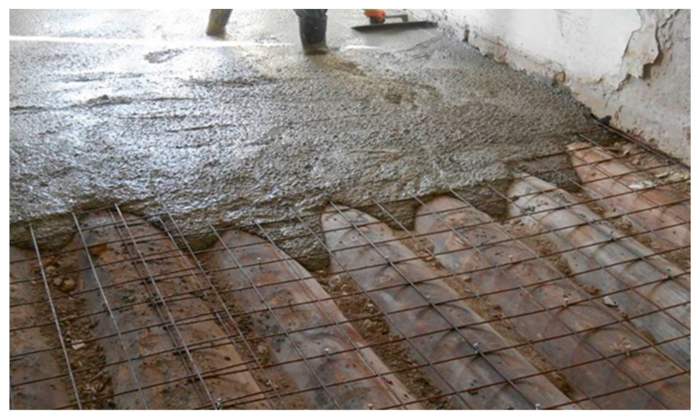
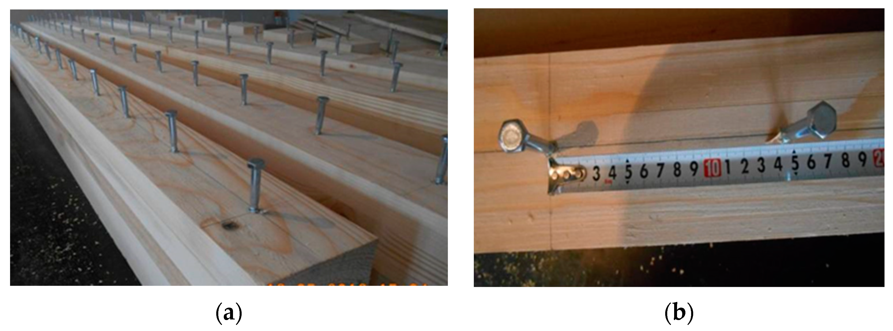
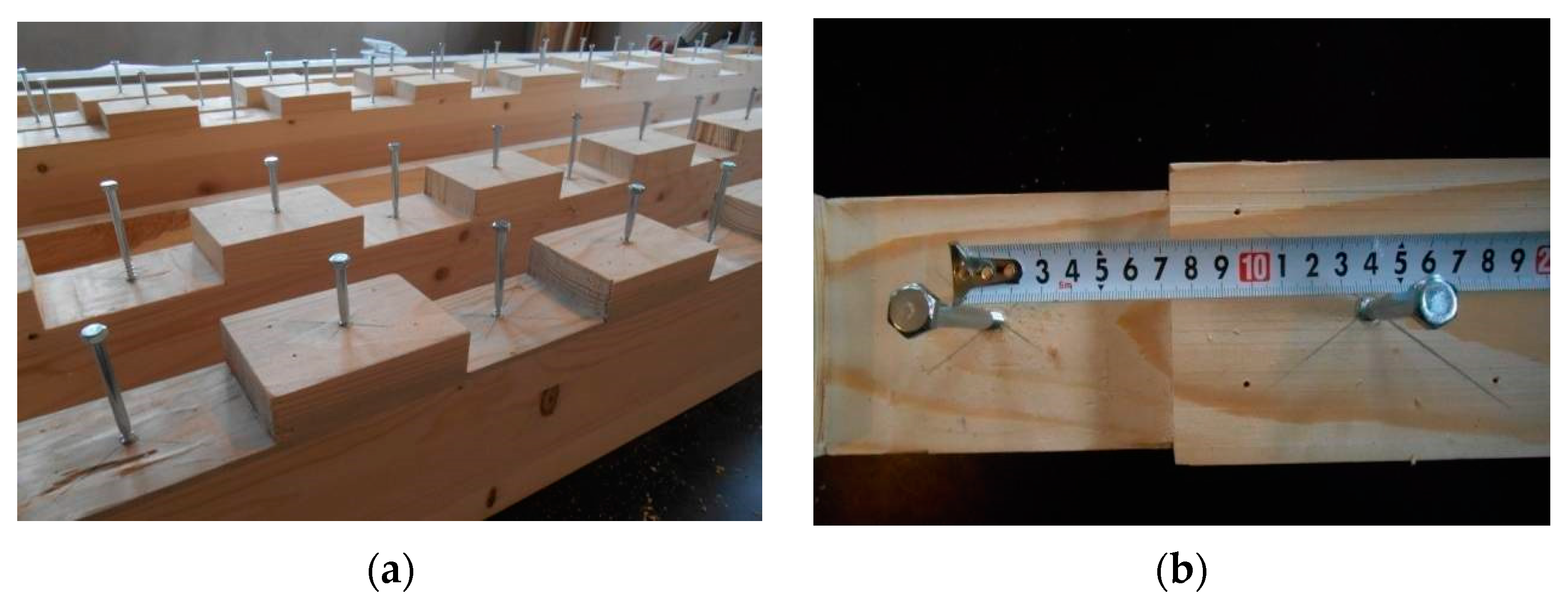
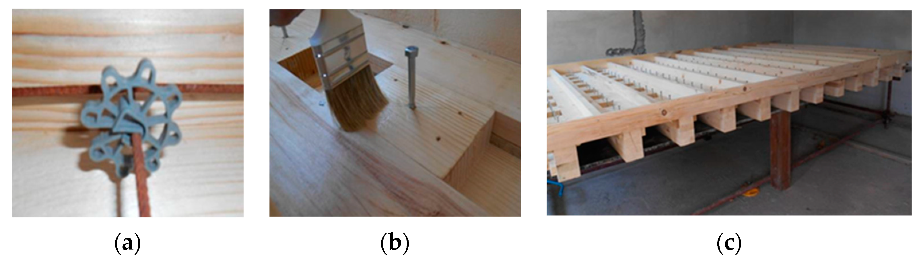
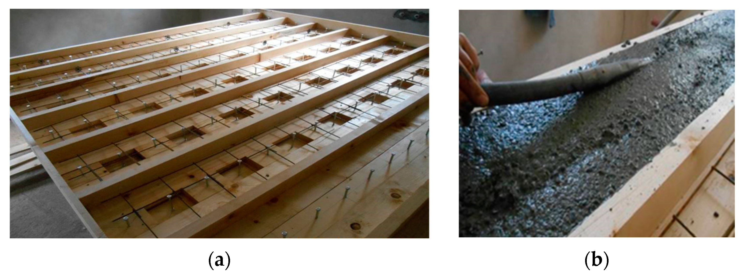
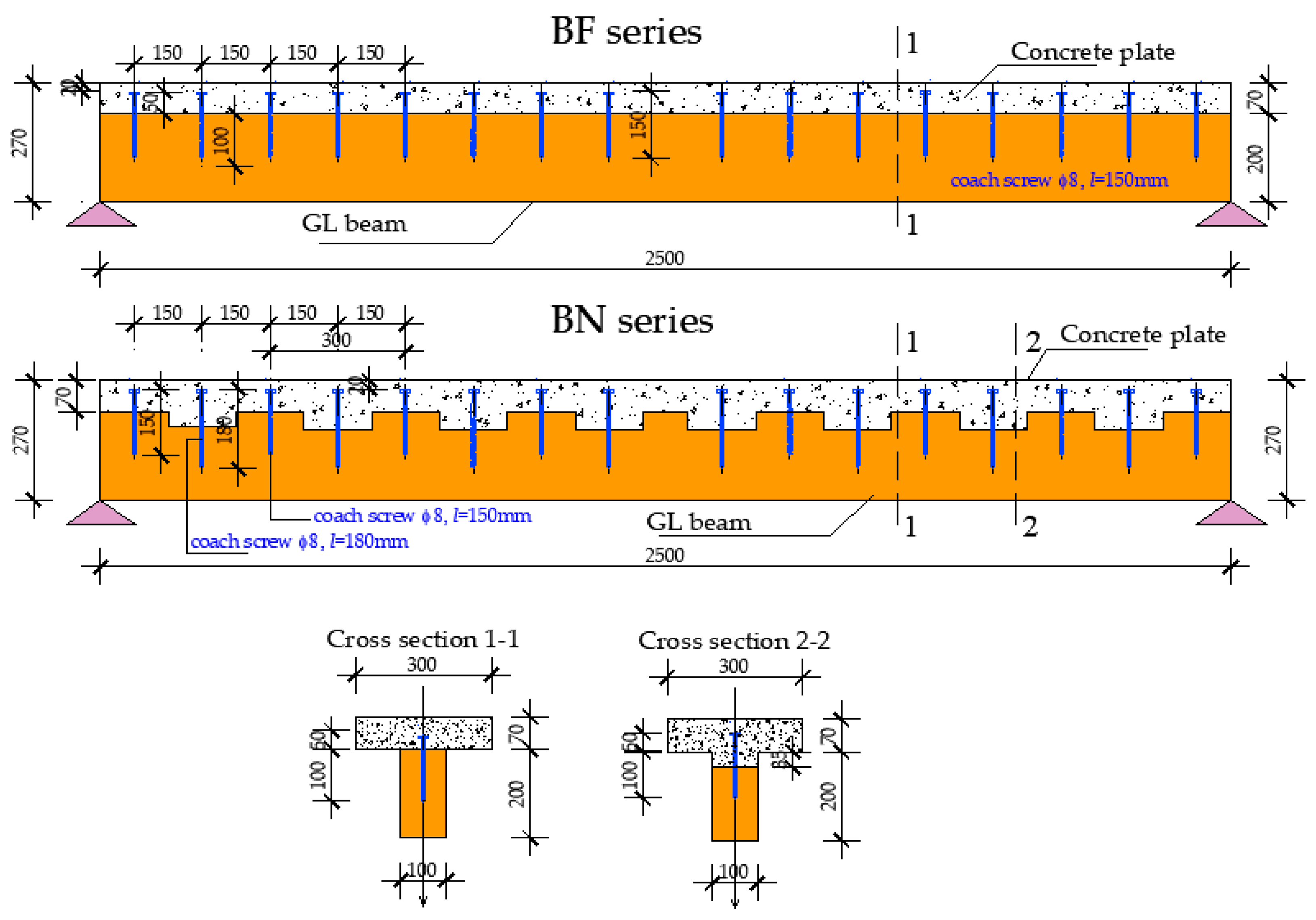
2.1. Materials and Models of TCC Beams for Experimental Study

Model specimens were designed as TCC simple beams with the total length of 2.60 m (clear static span 2.50 m), whose “T-type” cross-section was formed by coupling the GL beams (strength class GL24h-spruce) [34], and concrete slab (strength class C35/45), [35,36]. The cross-section dimensions of timber parts were 10/20 cm and of concrete 30/7 cm in both series.
The GL strength class was indirectly determined according to relevant EN standards for visual classification of coniferous timber and testing/determination of structural properties and density [37,38,39]. On the basis of the tested specimens (one sample for each property, 6 specimens) the three key parameters (density, bending strength and local modulus of elasticity) were determined. The average moisture of tested specimens was 13.71%, which was included in the result analysis. Testing results of key properties showed average density of 490 kg/m3 (characteristic 364 kg/m3, class C27), characteristic bending strength of 35.8 MPa (class C35) and characteristic bending modulus of elasticity parallel to the grains of 9.24 GPa (class C35). Additionally, 17 specimens with average moisture content of 10.03%, were tested by the tension test parallel to the grains [38]. Results showed that the characteristic tension strength was 24.97 MPa that led to class T24. Besides the fact that the strength class of the solid timber used is higher than C24, a conservative approach was applied due to the lack of possibilities to test the glued lines and finger joints. The glulam strength class of analyzed specimens was accepted as GL24h, according to EN 14080:2013 and EN 1912:2013 [39,40,41,42].
In order to choose the adequate concrete mixture, two mix designs were considered. The selected mixture contained wet aggregates in three fractions (0/4 = 40%, 4/8 = 25%, 8/16 = 5%), with fresh concrete density of 2325 kg/m3. The compression test with the corresponding test for determination of the modulus of elasticity was realized according to ISO 4012:2000 and ISO 6784:2000 on two samples with 3 specimens in each. The estimated strength class was C35/45 [43,44].
TCC model beams were designed in two ways, depending on the selected connection system between timber and concrete parts. Two series of model beams BF and BN (fasteners or notches with fasteners) consist of three specimens each.
The first series of beams (BF) was made in the traditional manner, using mechanical fastener-coach screws (inner/outer diameter 8/5.8 mm, total length l = 150 mm, S355) [45]. Coach screws are installed at the spacing of 15 cm along the whole length of the timber-concrete contact surface. Screws were driven into the timber part up to 100 mm deep, Figure 2, while the remaining 50 mm was in the concrete part of the cross-section.
The second series of beams (BN) was created by coupling of timber and concrete with a more complex connecting system that consisted of combination of parallelepiped notches and additional screws. Parallelepiped notches were cut at distance of 30 cm along the beam taking up the whole width, with dimensions depth/length/width= 35/150/100 mm. In the middle of each notch, coach screws with the outer diameter of 8 mm and length l = 180 mm were used, while in between notches, shorter coach screws d/l = 8/150 were applied. Using a connecting system made of two screws of different lengths screwed in the notches and on top of the timber beams, the screws were at a distance of 150 mm like in the BF-series, but participating in shear force resistance alternately-directly in timber/concrete interlayer or together with the notch filled with concrete, Figure 3.
The screws are screwed into previously drilled holes with 10% smaller diameter than the screw itself. The attempt to install screws without previously drilled holes led to screw failure due to high timber quality (GL24h) and low moisture content of the timber. The formwork for casting the concrete slab was positioned on a previously prepared elevated stable steel frame platform, Figure 4.
The formwork was made at the same time for all 12 beams, Figure 5. Before casting concrete into the formwork over timber beams, the screws were installed and notches were cut according to the previously described pattern. In order to prevent water transfer from concrete into timber, a transparent polish is applied over the upper parts of timber beams and the bottom and sides of the formwork. In this way, the adhesion between timber and concrete parts is reduced to a minimum, that is, the friction coefficient in the adherent surface of timber and concrete composite cross-section is reduced. The result of the reduced friction was that the biggest part of shear force in the adherent surface was being taken over by the connecting systems.
The concrete part of the cross-section was reinforced by a steel mesh (Q 131, MAR 500/560), positioned 20 mm from the bottom of the concrete flange using reinforcement spacers. During casting the concrete was vibrated so that notches were filled in a compact way, Figure 6. Particular care was taken to prevent concrete segregation because of per-vibrator usage and the fact that the concrete slab was only 7 cm thick.
The final geometry of the tested beams of BF and BN-series is given in Figure 6.

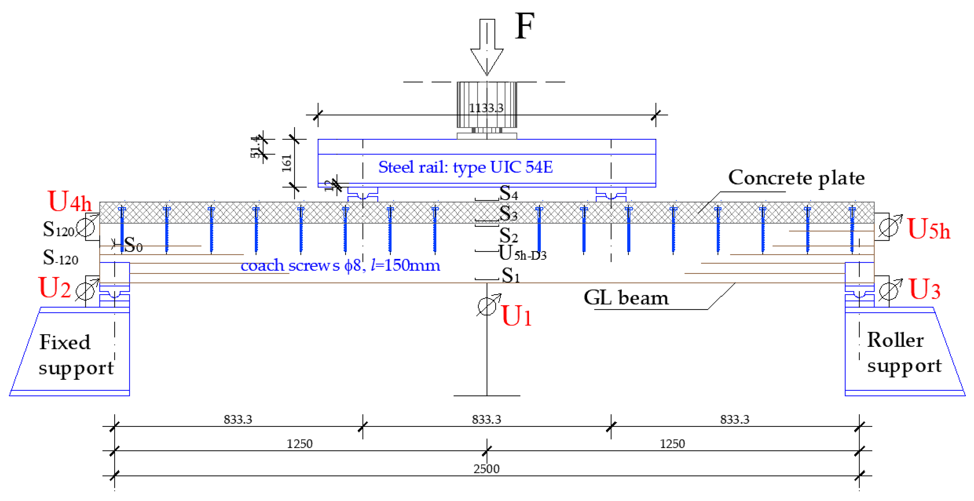
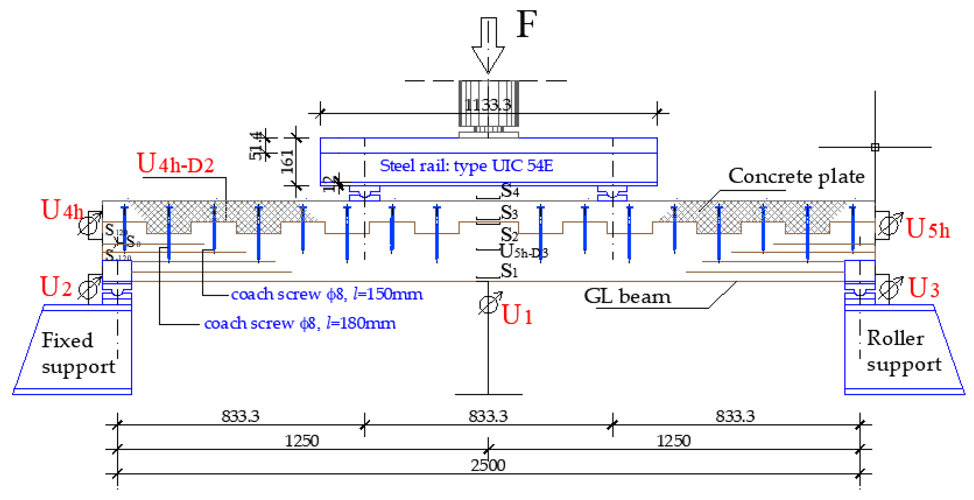
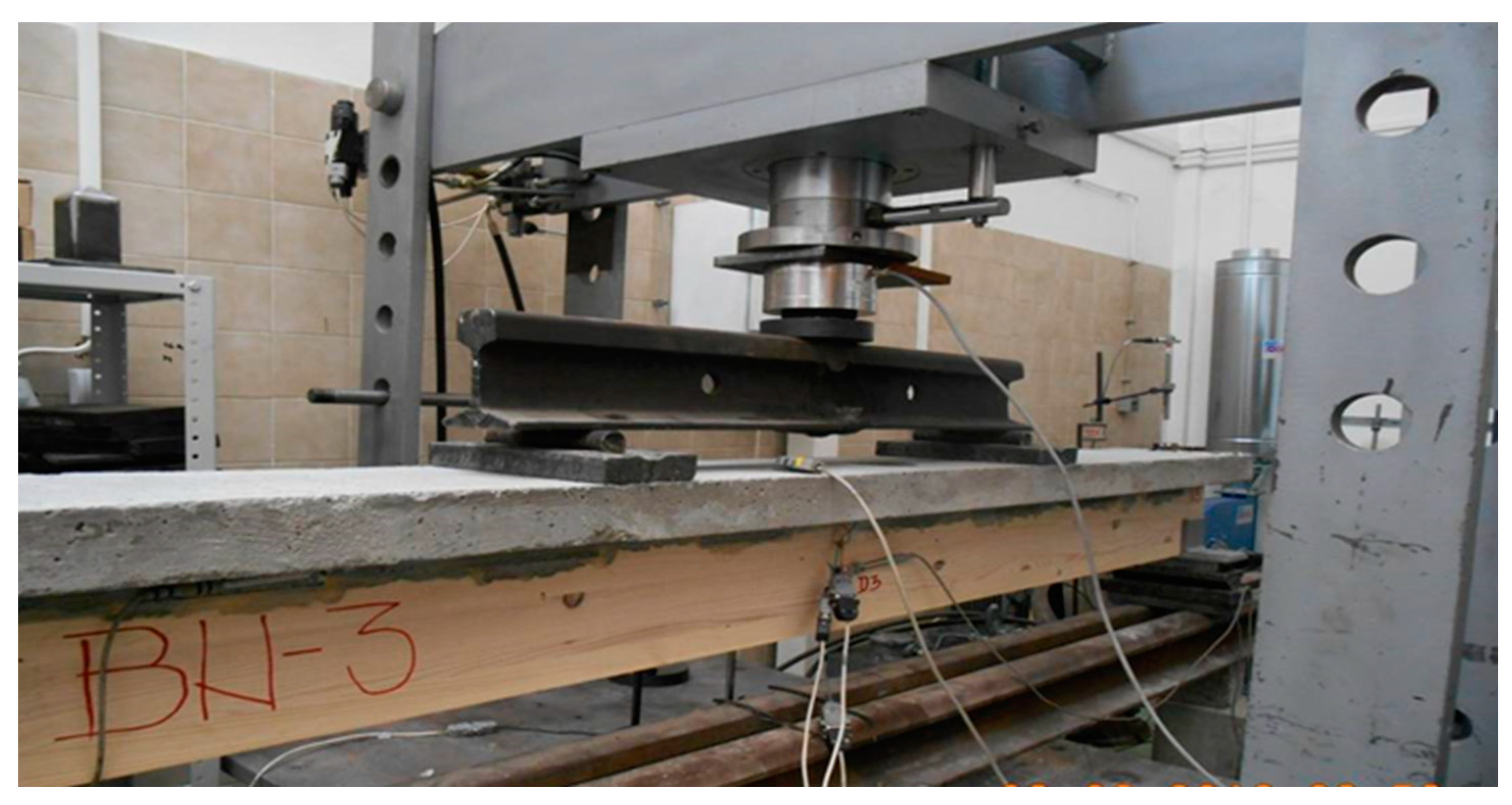
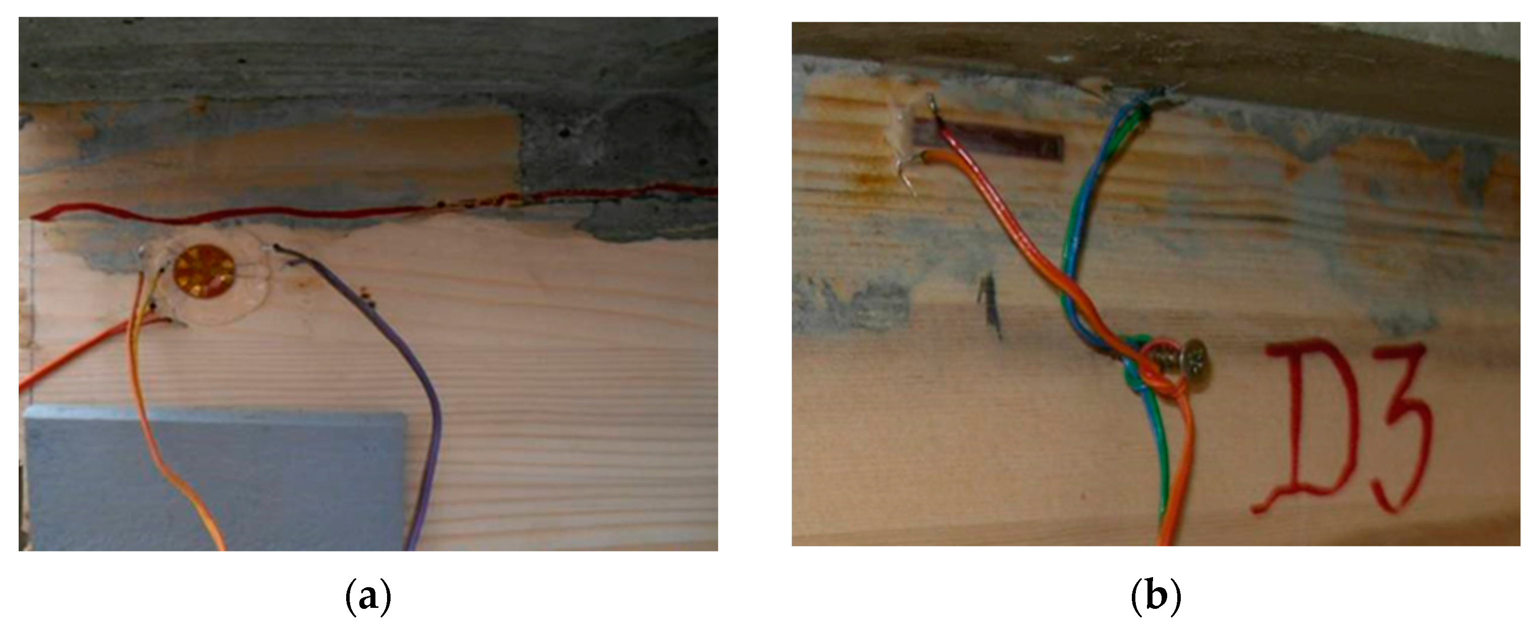
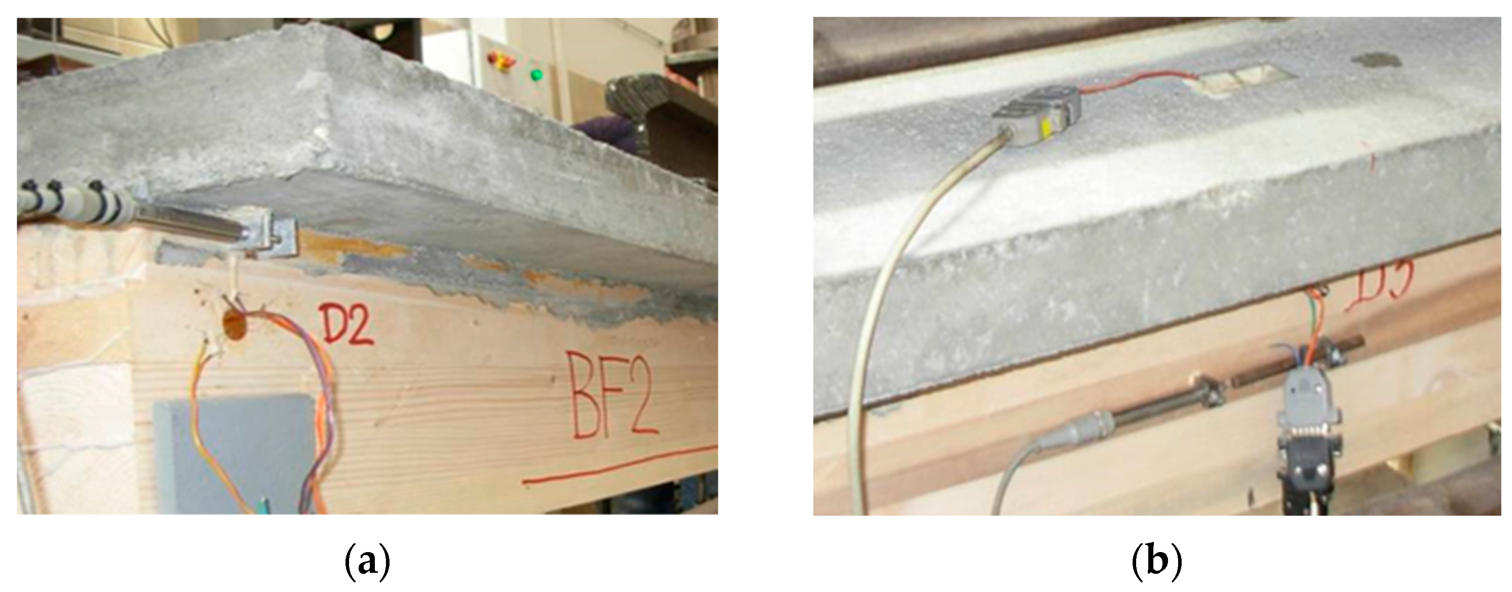
2.2. Testing Program and Setup of the Experimental Study

Testing of the bending performances of all six TCC beams of the BF and BN-series was carried out under a short-term monotonic loading up to failure, using laboratory measurement equipment described and presented below.
Load was applied by a hydraulic device, while load transfer on the TCC beam was done by means of 1.13 m steel rail. The distance between load points was 833 mm, which creates a symmetrically loaded beam in the thirds of span [38]. The fixed pin and roller support were done using 100 mm wide and 300 mm long steel plates and a steel roll with a diameter of 30 mm positioned in between. The beam was supported by steel contact plates with the same geometry and secured using vertical steel plate anchors necessary to provide the position of “T” cross-section beams and to avoid torsion. The load was applied within 300 ± 120 s until failure, with a constantly increasing rate of 1 mm/min.
The details about the test setup as well as about the position and description of instruments and measurement points used in experimental study of the TCC beams of BF-series are given on Figure 7 and Table 1, while for beams of BN-series on Figure 8 and Table 2.
Global deformations of the beam (displacements) were monitored by: LVDT-linear variable displacement transducers W50 for measuring deflections at mid-span and above the supports. LVDT was used for registration of horizontal displacement in the interlayer of timber and concrete. Measuring strain in the corresponding zones of concrete and timber parts of the cross-section mid-span, as well as in the support zone, was conducted using “Hottinger” strain gauges, having electrical resistance of 120 Ω with the various base lengths. Strain gauges were directly glued on the surface of concrete and timber using two-component glue X60.
The interesting details about test setup, measuring points and instruments during the experiments are illustrated through Figure 9, Figure 10 and Figure 11.

3. Results

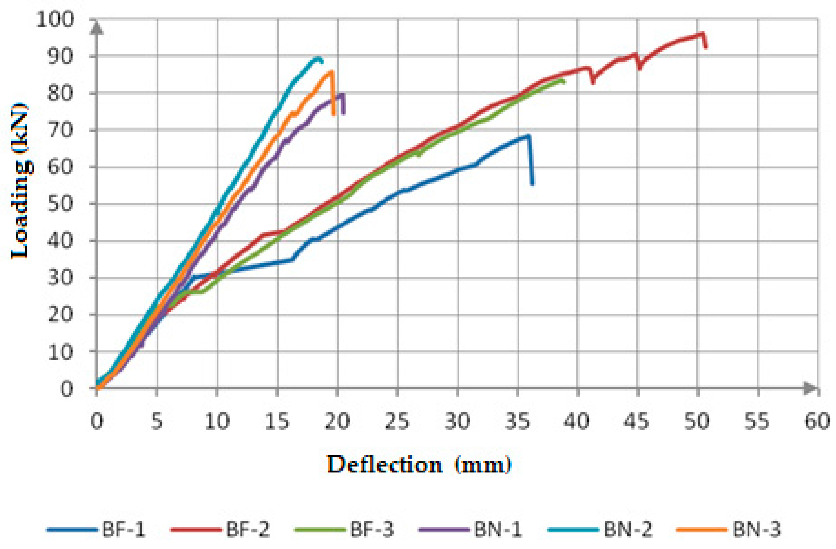
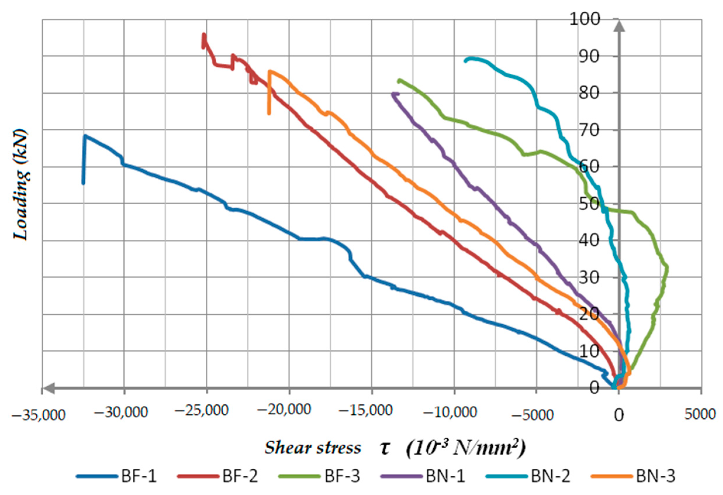
3.1. The Load-Deflection Diagrams of BF and BN-Series Beams

In Figure 12, the load–mid-span deflection diagrams of all TCC beams are shown. In the case of BF-series, the first tested specimen BF-1, showed an obvious discontinuation at the beginning of the test, but later regularly continued up to the explicit failure. This result influenced the average value of the max load for BF-series, as well as the average deflection in middle span. The max load for BF-series was in the range of 68.19–90.33 kN, Figure 13, while deflections were in the range of 35.73–44.74 mm (i.e., L/70-L/55.87, expressed in relation to span L), Figure 14. Despite an observed irregularity in first specimen’s behavior, the exhibited load-deflection relation could be considered as approximately linear up to the failure point, which indicates linear-elastic behavior of TCC beams of BF-series.
In the case of BN-series, Figure 12, all tested specimens showed a very steady performance related to mechanical and deformity parameters. Max load for BN-series was in the range of 79.67–89.43 kN, Figure 13, while deflections were in the range of 18.36–20.42 mm (i.e., L/136-L/122.42, expressed in relation to span L), Figure 14. This series of TCC beams exhibited an almost perfectly linear load-deflection relation so the BN-series could be considered to have ideal linear-elastic behavior up to failure. The reasons for such a phenomenon lie in the choice of the connecting systems used in TCC coupling, the high value of achieved stiffness and the fact that beams of a short span were used in the experiment.
Comparison of loading intensity which caused failure (max load values Fmax) for both series, Figure 13, expressed over average values in Table 3, show that mean Fmax = 80.65 kN for BF specimens is only about 5% lower than for BN specimens where mean Fmax = 84.96 kN.
Comparison of max mid-span deflections for both series, Figure 13, expressed over average values in Table 3, shows that BF-series specimens achieve a deflection mean value of Umax = 39.78 mm, while BN-series achieve a mean of Umax = 19.43 mm, which indicates about twice the average deflection in series of TCC beams connected only with fasteners.

3.2. Stiffness of the BF and BN-Beams Series

In order to compare the exhibited stiffness of TCC beams of both series during testing, beam stiffness was calculated from the corresponding load-deflection curves for each specimen in the linear range between 0.1 Fmax and 0.4 F max [38]. According to the equation for the calculation of deflection in the middle of the simple beam loaded by two concentrated forces in the thirds of the span, the bending stiffness El can be calculated as:
E I = 23 1296 ( F 2 F 1 ) L 3 ( w 2 w 1 )
where: F1: loading which corresponds to 0.1 Fmax value, F2: loading which corresponds to 0.4 Fmax value, w1: deflection value measured for the 0.1 Fmax loading value, w2: deflection value measured for the 0.4 Fmax loading value. L: beam span.
The calculated values of bending stiffness for all test specimens (BF and BN-series) are presented in Figure 15 and summarized with other relevant data in Table 3.

3.3. Comparative Analysis of the TCC Beams Results for BF and BN-Series

In order to summarize the measured and calculated data necessary for explanation of mechanical behavior of tested TCC beams of both series, Table 3 was created. Data about failure force, deflection value in the middle of the span, bending stiffness for each specimen and mean values for specific series, are given, together with specific measurements necessary for discussion.
The lower bending capacity of specimen BF-1 was expected, due to the nature of timber and could be explained by non-uniform quality of glulam in the region.
Small differences of Fmax mean values between BF and BN series indicate similar bearing capacity of analyzed beam series, but the two times lower average deflection in series BN indicates expected lower bending stiffness for BF series (32.86%). The calculation of characteristic values in the presented comparative analysis is omitted because of the small number of specimens in the sample (series). Certainly, for a proper application of complex connecting system applied in BN-series, an extensive investigation is needed.
Bearing in mind the span of tested composite beams as well as the shear force occurring in the connection plane of the timber and concrete elements, the influence on the behavior of the connecting systems, and ultimately on the level of the achieved coupling effect, special attention was paid to the state of strain, stresses and displacements in support zones. Three strain gauges in the form of a “rosette” (at angles to the horizontal plane of 0°, 120° and −120°) were placed (Figure 7 and Figure 8) in order to measure corresponding strains in the specified directions.
Based on the strain values obtained in the specified directions, (α = 0°, 120° and −120°), it is possible to calculate the values of main strains, ε1 and ε2 in the observed points of the support sections, using the expression:
ε 1 / 2 = ε 0 + ε 120 + ε 120 3 ± 1 3 ( 2 ε 0 ε 120 ε 120 ) 2 + 3 ( ε 120 ε 120 ) 2
The angle, at which main strains occur, in respect to the horizontal line, is determined by the equation:
t g 2 φ 0 = ε 120 ε 120 2 ε 0 ε 120 ε 120 3
Values of main stresses σ1, σ2 and shear stress, τ12 can be calculated using:
σ 1 = ε 1 ν ε 2 1 ν 2 E ,   σ 2 = ε 2 ν ε 1 1 ν 2 E ,   τ 12 = σ 1 + σ 2 2 .
where: E: is the value of the timber modulus of elasticity obtained experimentally, ν: is the Poisson’s coefficient (approximate value for spruce timber is 0.4).
By using Equations (2)–(4) and experimentally obtained values for strain in the support zone, relations indicating development of main strains and shear stress states in the function of incrementally increased load can be established.
Shear stress states in the support zones of simple beams are important because they are loaded with transversal intensity. This primarily defines the load bearing capacity of the timber part of the cross-section and then defines the shear force transfer through the connecting system. As important factors for mechanical analysis, the measurement and calculation of shear stress through the rosette of strain gauges (Table 1 and Table 2) at a fixed support are given through a comparative presentation of the shear stress-load increase relation at the support zones for each tested beam separately in Figure 16. The values of shear stress in the BN-series beams ranges from 10–20 N/mm2 and in the BF-series beams, from 15–35 N/mm2.
A comparison of experimentally obtained and calculated values of load-bearing capacity and stiffness according to the EC5 requirements was done in [33]. BF beams, when calculated with estimated slip modulus for screws given in EC5, showed a direct relationship with tested specimens, i.e., the bearing capacity is about 28% lower than obtained during the tests (due to the application of partial safety factors for materials γm = 1.25 and of the modification factor, kmod = 0.9 in calculation). This refers to the rather well-estimated values of the slip modulus for screws in the standard. For the serviceability limit state, the stiffness calculated for the service load with deflections limits of l/300 corresponds to the experimental one, while the max ultimate mid-span deflection is 4.65 times higher than prescribed ones, which indicates the “reserve” in bending stiffness of about 27%.
For BN beams it was not possible to make such a direct comparison according to estimated values, so, in order to get the input parameters for an analytical comparison, the connecting screws-notches system was experimentally tested according to EN 26891. The obtained values of the slip modulus were used in the calculation, together with estimated values for screws without notches according to EC5 and its verification procedure. Opposite to the BF series, calculated values for bearing capacity and stiffness expressed through the theoretical value of Fmax on the basis of EC5 equations were higher than obtained in the test. The overestimation of about 40% indicates that the EC5 procedure is not applicable for verification of the complex system with notches and screws even in approximate manner [33].

4. Discussion

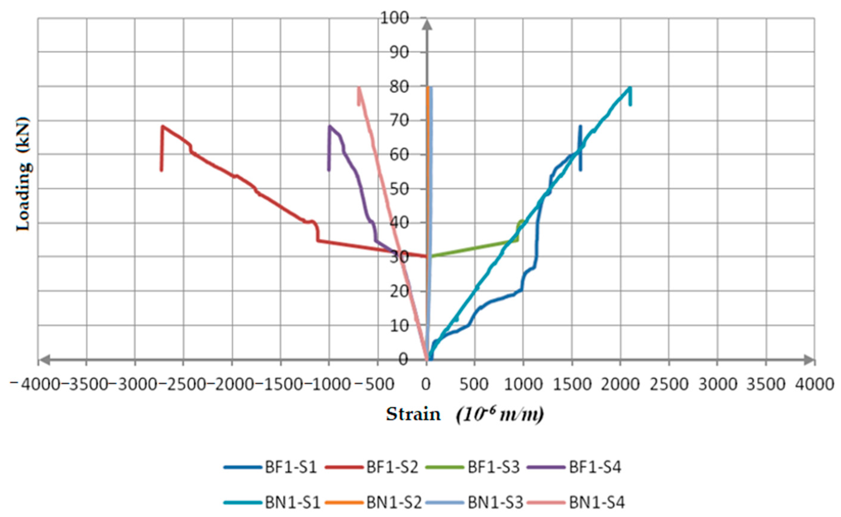
4.1. Strain Distribution in BF and BN-Series Beams

The development and change of stress states during the load application were monitored by strain measuring according to the detailed description given in Figure 7 and Table 1, as well as in Figure 8 and Table 2. Strains were monitored up to final steps of maximum loading for both series.
The development of strains in the bottom and top sides of the mid-span cross-section is presented in Figure 17 for both series BF and BN. These diagrams show strain in pressure and in tension as negative and positive values. Acquired data through measuring points S1, S2, S3, S4 in the time interval of 1 s, make it possible to present strain distribution per height of the coupled cross-section for any level of loading.
BF-series: The distribution of strains across the height of the cross-section is expressed as elastic, i.e., the strain development is approximately linear. The strain values in adjacent fibers, bottom side of concrete and top side of a timber cross-section (measuring points S2 and S3) have almost the same absolute values which indicate the co-acting of the elements of a composite beam and the existence of the real effect of coupling achieved by built-in fasteners. Such a development of strains in the bottom and top sides of timber and concrete is present up to a level of 20–30% of Fmax, and after that, due to excessive tension strength in concrete (crack development) there is a failure of the measuring point S3. All three tested beams of the BF-series are characterized by such a development of strain in the bottom, tensioned concrete zone and it indicates a low level of crack initiation which begins with the development of micro-cracks in concrete. The fact is that beams have a stable performance up until the failure for which an additional 70–80% of load application is needed.
It could be said that the BF beams, in the first, elastic phase, with a lower loading level, act as rigidly coupled. After that, there is a phase characterized by an elastic coupling followed by the failure of screws due to the development of shear force in the interlayer. There is crack propagation in the tensioned concrete zone and increased strains in the bottom and top sides (measuring points S1, S2 and S4).
According to the achieved results and the presented diagrams of the load–strain relationship in the bottom and top sides of the timber and concrete parts of the coupled cross-section, it can be concluded that:
  • At the bottom side of the timber beam, there is a tension strain (the blue line), with values in the range of 2–4‰.
  • At the top side of the timber part, the pressure strain (the red line), is in the range of 2.7–3.2‰. The development of this dilatation in all three tested samples is approximately linear and steady.
  • At the bottom side of the concrete part (the green line) and the top side of the timber part, the measuring points S2 and S3 have an almost identical progress up to the level of 20–30% of Fmax. After that level of applied load, there is a very short tension strain development in bottom side of the concrete, up to the failure of the strain gauge. In continuation, diagrams separated regards to the stress, i.e., the pressure at the top side of timber (S2) and tension at the bottom side of concrete (S3). Thus, it can be concluded that after approximately 30% of Fmax, there is a horizontal displacement in the interlayer of timber and concrete, and creation of two neutral axes. The BF beams, are characterized by a high deflection in the middle of the span, Table 3, by propagation of micro-cracks which is clear proof of concrete failure in tension.
  • The pressure strain at the top side of concrete (the purple line) has a steady, almost linear development and its value is within the range of 1–2‰. It is lower than the value of the ultimate strain due to the pressure in concrete of 3.5‰ which means that there is no concrete plasticization in that zone.
BN-series: The development of strain in the bottom and top sides of timber-concrete parts of BN beams has an approximately linear form up to the failure. The measured strains at the top side of the timber (S2) and the bottom side of the concrete parts (S3) have approximately the same absolute values. This indicates the co-acting of elements and the existence of a high degree of coupling realized by applied connecting systems. The measured strain values are almost equal to zero and have a steady development during the load application up to the point of failure. These results lead to the conclusion that BN-series beams act as homogeneous sections and could be described as rigid coupling representatives.
The values of the corresponding measured strains and their development up to the failure point, both in timber and concrete, in all three test specimens, are almost the same.
On the basis of the acquired results, it could be concluded:
  • At the bottom side of the timber part there is a tension strain (the blue line) and its value for the BN-series ranges from 1.4–2.1‰;
  • At the top side of the timber part, the development of the pressure strain (the red line), is in the range of 0–0.5‰;
  • The strains at the bottom side of the concrete part (the green line) and the top side of timber part (the red line), have an almost identical development during the load application. The neutral axis of the TCC cross-section, during the higher levels of loading, is near the timber-concrete interlayer. Almost equal values of strains in adjacent bottom and top sides of timber and concrete parts indicate a high level of coupling, that is, a low level of slip in the timber-concrete interlayer,
  • The pressure strain at the top side of concrete (the purple line), up to the failure has a steady, linear development, and its value ranges from 0.6–0.7‰. It is far below the value of ultimate strain of the pressure in concrete of 3.5‰, which means that there is no brittle concrete failure.
The quality and quantity analysis of the strain development while applying load on the BN-series beams indicates a linear performance up to the failure. This proves a high level of stiffness of the beams, and, consequently, their low ductility, which, in some cases of extreme dynamic loading, could be a disadvantage. The changes in the strain values in the compressed concrete zone and tensioned timber zone are small, what indicates the stiffness of the fastening systems and homogeneity of the cross-section.

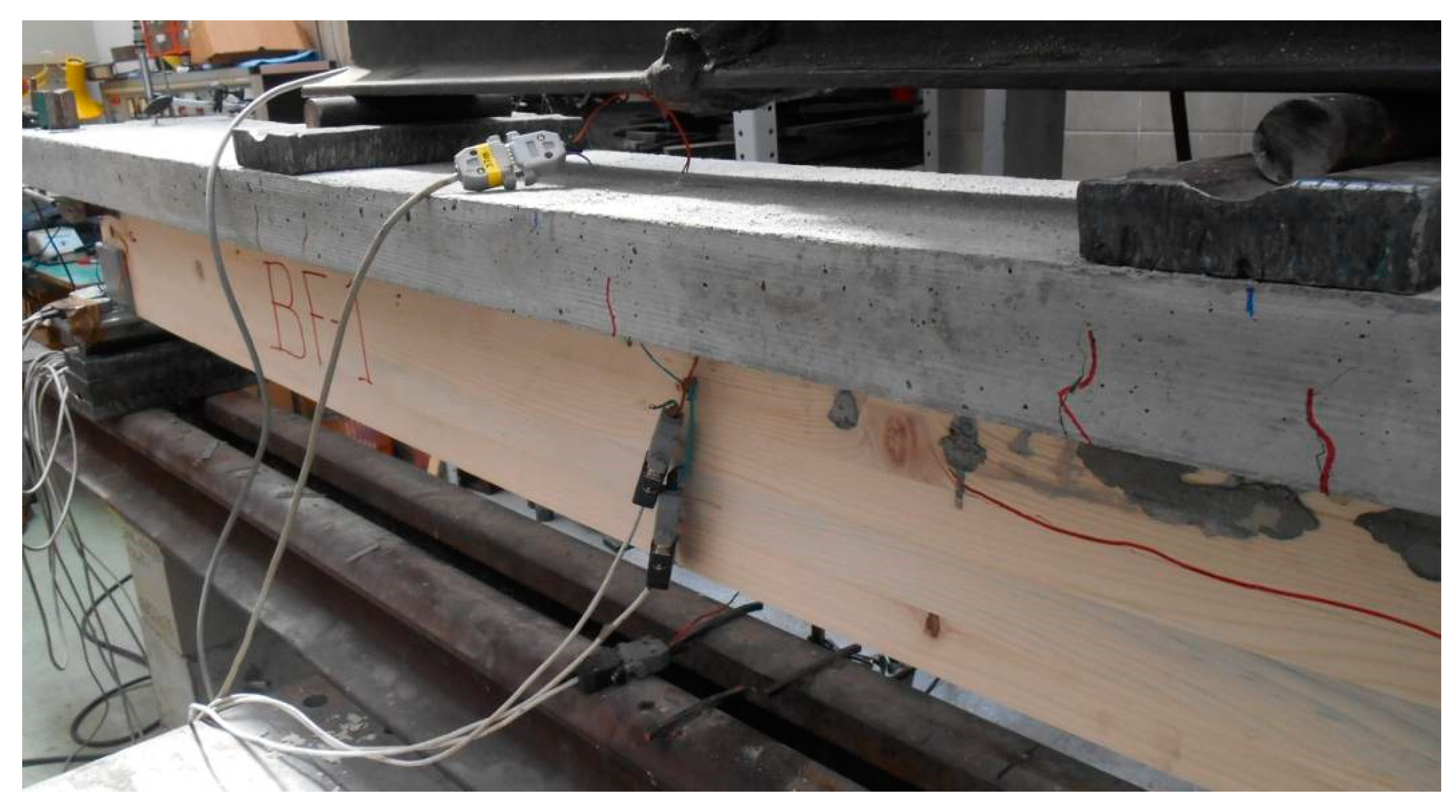
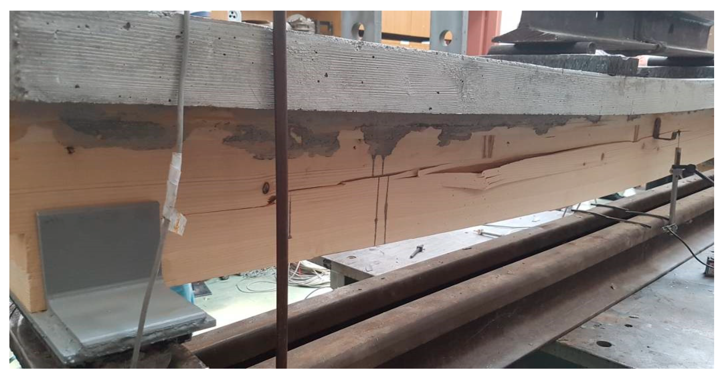
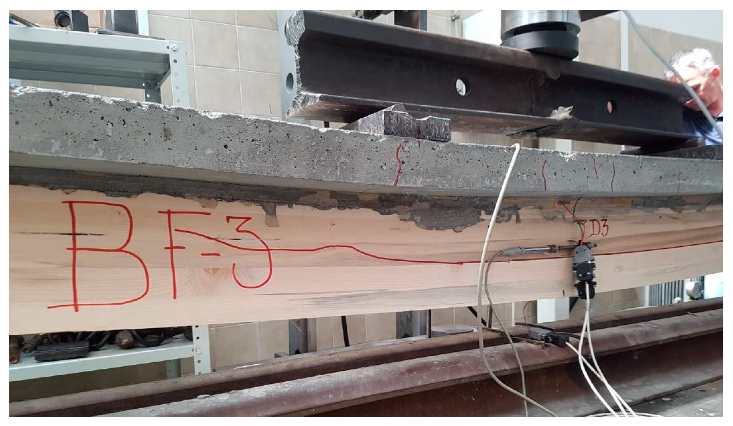
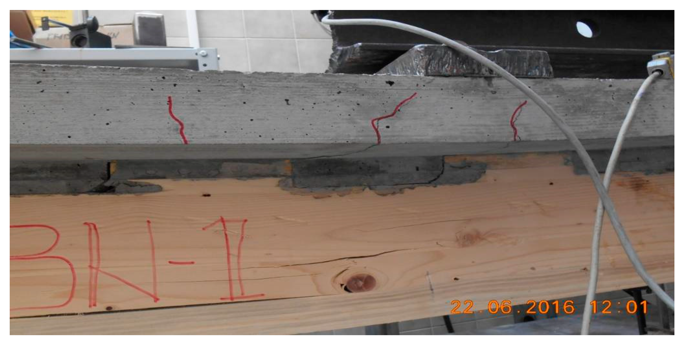
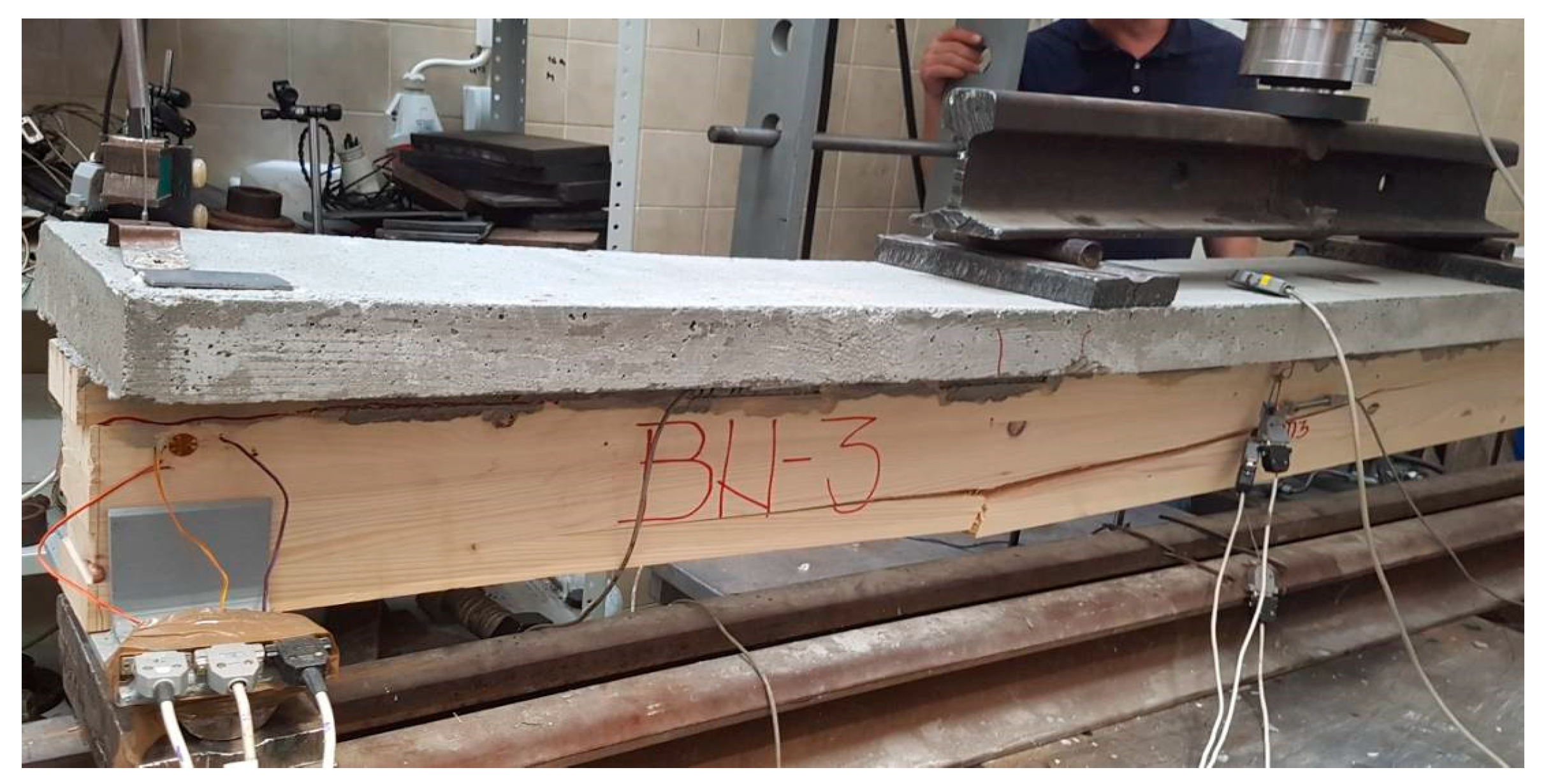
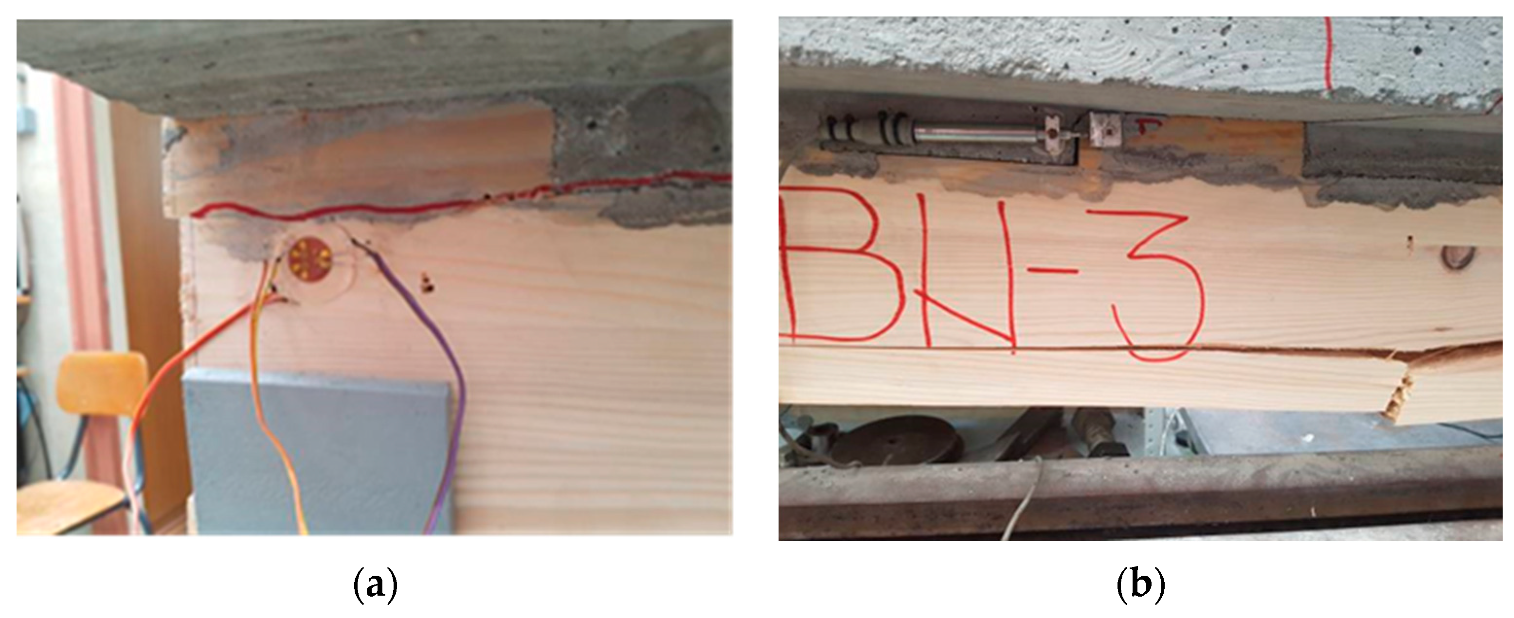
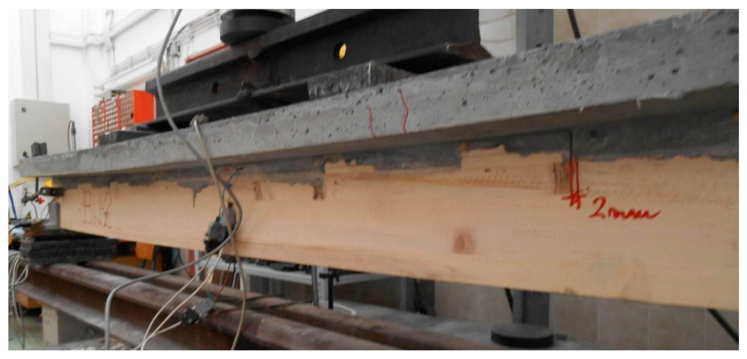
4.2. Failure Mechanisms of BF and BN-Series Beams

BF-series: Composite beams of the BF-series (BF-1, BF-2 and BF-3), showed nearly linear-elastic behavior which is obvious from the load-deflection diagram, Figure 12.
Failure mechanisms due to timber tension stress in the middle third of the span and at the bottom side of the concrete slab, followed by sound and sudden brittle failure, are dominant for BF-series. The failure of the connecting systems (screws), due to embedding strength of the timber and bending stress of the screw (failure mode II, [46]), is an additional element in completing the picture of failure mechanisms of the tested BF specimens. In the support zone, there was a 4–4.5 mm horizontal displacement in the timber-concrete interlayer which is a direct consequence of the fastener failure mode.
The failure of the beams always occurred in the zone of the timber defects (knots, the lamellas with inclined angle of grains, in regard to the longitudinal direction). It was observed that, after the initial crack, a horizontal splitting at the position of the neutral axes progressively advanced with an increase of loading up to the support. This, among other factors, is the consequence of the small span of the tested beams. At the same time, this indicates that load bearing capacity of the tested BF-series beams is completely consumed by reaching the limit values of the shear stress.
The failure of beam BF-1, which occurred in the support zone due to a horizontal shear in the middle of the timber height and outside the glued lines (10 mm long), is an explicit example of shear failure. Before the failure in the timber part, the cracks occurred in bottom side of the concrete part in the zone of load points, Figure 18. The development of the cracks is obvious, but with openings smaller than the permitted crack width (a < 0.3 mm). None of the tested beams showed signs of plasticization in the compressed zone of the concrete part of the cross-section. There was no failure in the concrete part of the cross-section during loading, and the first cracks were observed just before the timber failure i.e., prior to reaching the maximum deflection of the beam.
In Figure 19, the beam BF-2 is shown after the failure. The failure mechanisms imply failure was due to reached tension and shear strength limits in timber, with a pronounced splitting in the mid-span of the timber beam and cracking close to a neutral plane along the whole length of the beam. Also, there were indications of cracks in the bottom side of the concrete part. The beam BF-3, Figure 20, had a failure mechanism very similar to BF-2.
None of the tested beams showed any signs of plasticization in the compressed parts of the glue-laminated timber in mid-span, except certain plasticization in timber due to the compression strength perpendicular to the grain in the support zones of the coupled beams that occurred in late phases of loading.
BN-series: Composite beams of the BN-series (BN-1, BN-2 and BN-3), showed linear-elastic behavior up to failure with a high level of similarity between specimen behaviors, which can be seen from the load-deflection diagrams, Figure 12.
Despite the similar level of max applied load Fmax, the failure modes of BN beams were different.
In the tested BN-1 and BN-3 beams, the failure occurred due to the initial failure in the tensioned part of the laminated timber in the middle third of the beam span. It happened suddenly, followed by a loud and abrupt failure of timber, which is a sign of tension failure in timber. The initial failure occurred in the timber part in zones of defects (knots, the glued lamellas with grains inclined along longitudinal direction), Figure 21.
With increasing load and taking into consideration the beam span, further failure development occurs in the form of horizontal or inclined crack lines which go towards the supports, but do not reach them, Figure 22. Due to exceeded tension strength in mid-span of the beam there was pronounced development of cracks in the concrete slab strengthened by the concrete notches reinforced by screws. From that zone to the right and left, there is failure in the notch joint of timber and concrete which grows bigger as it approaches the support.
In the left support of the BN-3 specimen, there was a total destruction of the end notch and surrounding timber caused by shear and the horizontal displacement of 12 mm, Figure 23a,b. Compared to BF-series, beams of BN-series have a higher stiffness level. Failure due to excessive tension strength parallel to the grains occurs in the mid-span, but in the lower third of timber cross-section height. With increasing load, the neutral line goes upwards, stresses are transferred to the timber-concrete joint zone and horizontal displacement of the elements of the connecting system was observed. Simultaneous failure occurs due to excessive timber tension strength in the middle third of the span, timber shear strength in the support notches and concrete tension strength in the notch zone.
It is necessary to emphasize that the failure always occurred in timber and never in glued lines of lamellas. This indicates that the load bearing capacity of the tested BN-1 and BN-3 beams is achieved completely by reaching the shear stress in the support cross-sections.
BN-2 beam, with an approximately equal level of applied max loading and reached deflection, shows completely different behavior, i.e., shows behavior similar to the BF specimens. The failure occurred in the right support zone due to an excess of shear stresses and the cracks develop horizontally towards the left support. There is a noticeable symmetric horizontal displacement in the notch joints rising up to the failure point in the middle of the span.
Prior to the failure in the timber part of the beam, concrete cracks in the zone of load points were detected in the thirds of the beam span. The crack development was obvious, going up to the half of the height of the concrete slab, Figure 24. In the notch zone they have perpendicular direction in regard to longitudinal direction of the composite beam. None of the tested beams had any signs of plasticization in the compressed zone of the concrete part or in the compressed zone of the glued laminated timber, except in the support zone due to excessive compression strength perpendicular to the grains in timber (plasticization of 3–5 mm noticed in final steps of loading). No significant plasticization was noticed between the concrete notches and the timber notches due to specific local stresses because of the previously caused timber shear failure parallel to the grains.

5. Conclusions

On the basis of experimental results, observed mechanical behavior and failure modes of tested beams BF and BN-series, as well as their comparative analysis, the following could be concluded:
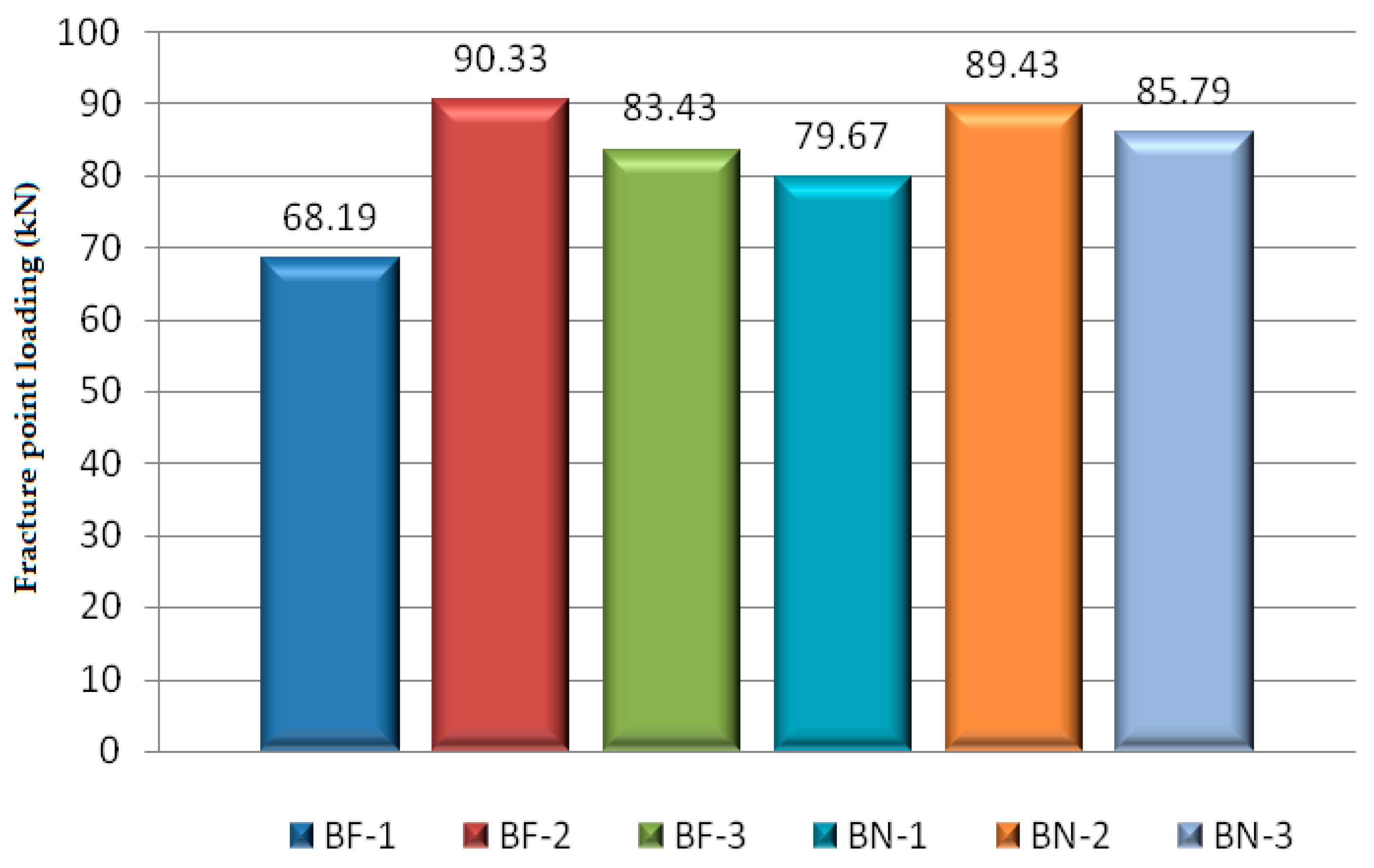
  • The average bearing capacity of two beam series, BF and BN, with the same spans and cross-section geometry, but with different coupling system, differs by a negligible 5%.
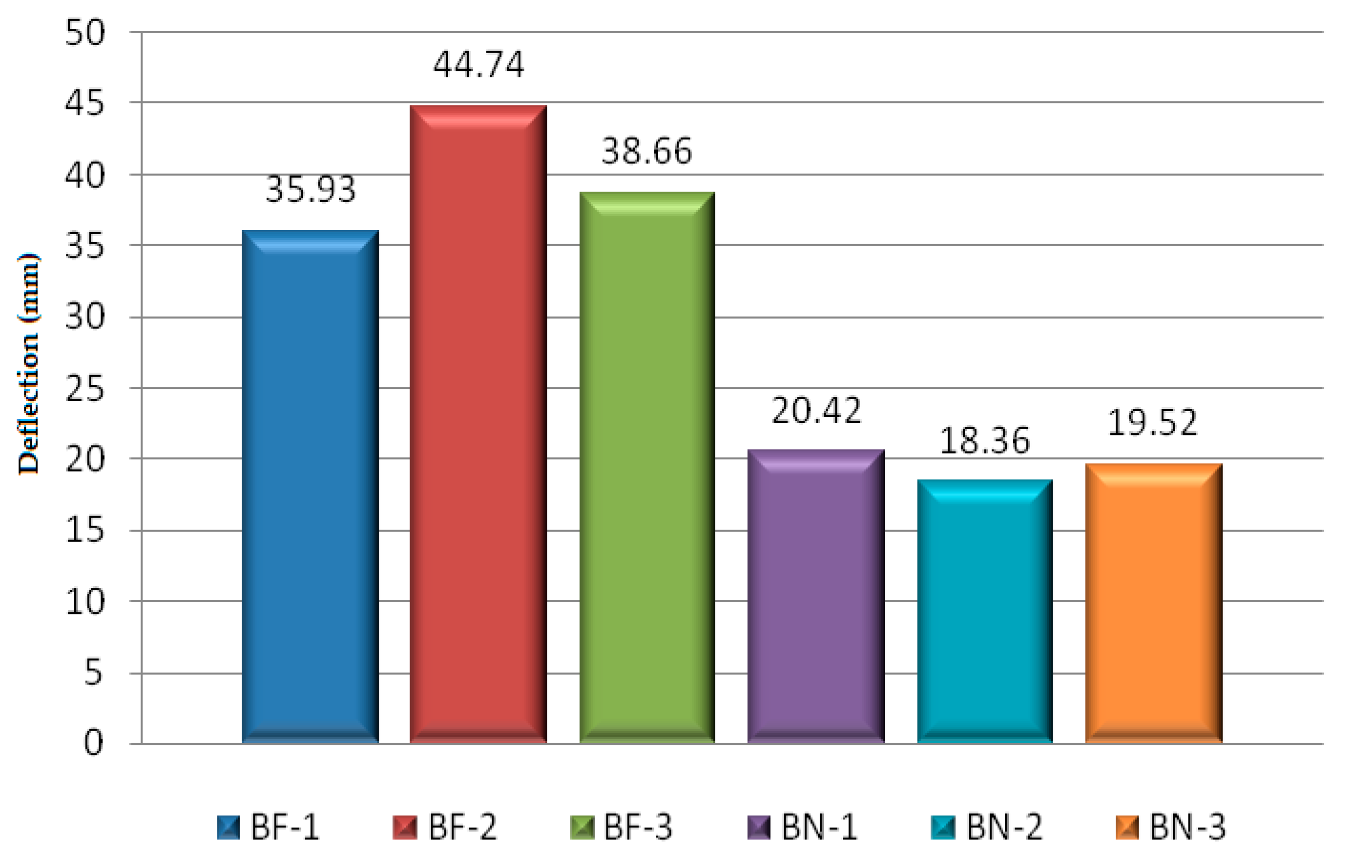
  • BN beams coupled with screws and notches show twice as low average deflection compared to BF beams where only screws were applied.
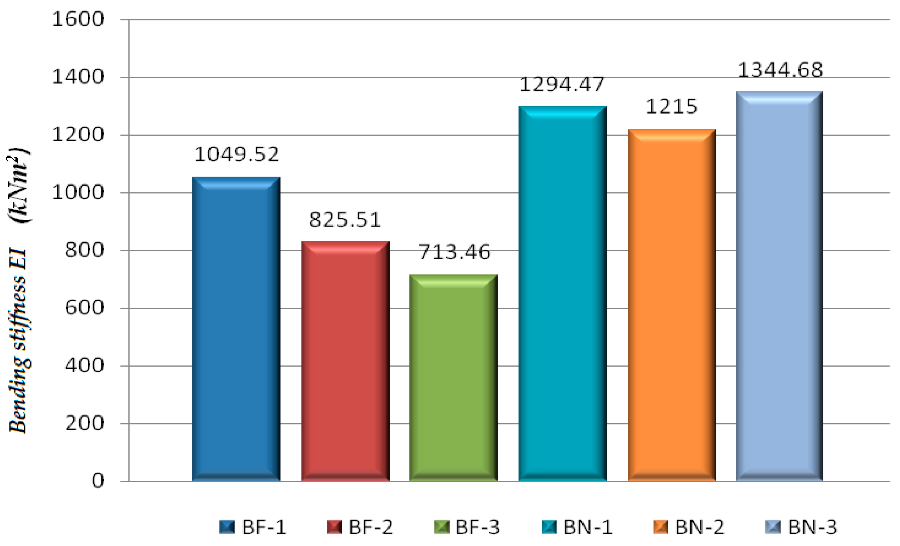
  • Recorded load-deflection curves for both beam series could be considered as linear-elastic, while behavior of BN-series could be taken as ideal. The calculated average effective bending stiffness of BF and BN-series differs 32.85%, in favor of BN beams.
  • Comparative analysis of measured load-bearing capacity and stiffness with design calculation according to EC5, indicates good coincidence for BF-series where only screws were applied, while for BN-series with screws and notches leads to overestimation of 40%.
  • “Rigid” coupling in BN-series was evaluated by analysis of strain development in beam mid-span cross-sections, where linear strain behavior (almost equal to zero with a steady development) in the timber-concrete interlayer was recorded. The BF-series beams, after about 30% of max loading, showed signs of “softening” of connecting system and horizontal displacement in the timber-concrete interlayer.
  • Failure mechanism of BF-series is dominantly achieved by tension strength of timber in middle third of span, while in BN-series simultaneous failure occurred due to tension and shear parallel to the grains. The average values of the horizontal interlayer displacements (U4h) measured in the support zones of the BN-series are about six times lower than the ones in the BF-series, which is the direct consequence of the connecting system used in each sample.
The presented research was conducted as a preliminary one, with the aim of a detailed inside view and comparison of the behavior of TCC beams with screws only or with the screws and notches, in order to estimate the possibilities of practical application in the design and rehabilitation of structures in the region, with locally graded timber.
The limitations of the presented research certainly lie in the small number of examined specimens, as well as in relatively short beam span (due to available funds, testing equipment and laboratory space) and therefore cannot be used for generalization of conclusions. It would be more suitable for the research itself if a third group of samples was included: specimens with only notches reinforced with screws, without application of screws at the mid-spacing between the notches. In that case, the research would have a more consistent character, would be comparable with the literature’s results and would have more data for comparative analysis between samples. In that case the verification by the EC5 gamma procedure would probably be more precise for the BN-series (the combination of the coupling with the screws and notches reinforced by screws).
However, the experience gained through these experiments was beneficial in regard to the significance of quality of built-in materials, as well as in regard to detailed analysis of failure modes and the contributions of particular components to composite action. The locally available timber showed high quality in laboratory tests on small specimens, but the structural size specimens showed inconsistency of visual classification. The screws in mid-spacing of notches additionally contributed to the rigidity of the connecting system and TCC beam stiffness, but their participation compared to screws only or notches only reinforced by screws was not evaluated.
Although the future directions of the research in the field of TCC structures could be numerous, the prospects for our future research are:
  • Variation of connecting systems with the aim of finding the optimal and suitable types with the adequate degree of composite action, which will be easy to make and reliable in solving of various structural problems, especially rehabilitation and strengthening of timber floor structures (widely present in the region);
  • Application of lightweight and “green” concrete (based on agricultural waste widely present in the region) for coupling with timber beams;
  • Experimental campaigns in laboratory and in situ conditions, with observed long-term load behavior,
  • Collection, processing and innovation of experimentally determined knowledge and experience, with calculation and numerical modeling procedures, with the intention of implementation into national standards.

Author Contributions

Validation, S.R.; Formal analysis, T.K.M.; Writing—original draft, R.C.; Supervision, D.K. All authors have read and agreed to the published version of the manuscript.

Funding

This research received no external funding.

Data Availability Statement

Data are contained within the article.

Conflicts of Interest

The authors declare no conflict of interest.

References

  1. Cvetković, R. Behavior of Composite Timber-Concrete Structures with Bending Actions. Master’s Thesis, Ruhr University, Bochum, Germany, 2002. [Google Scholar]
  2. Stevanović, B. Analysis of Composite Timber-Concrete Structures. Ph.D. Thesis, University of Belgrade, Belgrade, Serbia, 2003. [Google Scholar]
  3. Cvetković, R.; Stojić, D.; Marković, N.; Trajković, M.; Živković, D. Repair and Strengthening of Timber Floors of Pančevo Diocese by Timber–Concrete Coupling Technique. J. Tech. Gaz. 2018, 26, 1191–1198. [Google Scholar]
  4. Maslak, E.; Stojić, D.; Drenić, D.; Mešić, E.; Cvetković, R. Strengthening of Composite girders timber-concrete with presstresed reinforcement. Građevinar 2020, 72, 1001–1010. [Google Scholar]
  5. Dias, A.M.P.G. Mechanical Behavior of Timber-Concrete Joints. Ph.D. Thesis, University of Coimbra, Coimbra, Portugal, 2005. [Google Scholar]
  6. Clouston, P.; Bathon, L.; Schreyer, A. Shear and bending performance of a novel wood-concrete composite system. J. Struct. Eng. 2005, 131, 1404–1412. [Google Scholar] [CrossRef]
  7. Ceccotti, A.; Fragiacomo, M.; Giordano, S. Long-term and collapse tests on a timber-concrete composite beam with glued-in connection. Mater. Struct. 2006, 40, 15–25. [Google Scholar] [CrossRef]
  8. Deam, B.L.; Fragiacomo, M.; Gross, L.S. Experimental behavior of prestressed LVL-concrete composite beams. J. Struct. Eng. 2008, 134, 801–809. [Google Scholar] [CrossRef]
  9. EN 1995-2; Eurocode 5: Design of Timber Structures—Part 2: Bridges. European Committee for Standardization: Brussels, Belgium, 2004.
  10. Gutkowski, R.; Brown, K.; Shigidi, A.; Natterer, J. Investigation of notched composite wood concrete connections. ASCE J. Struct. Eng. 2004, 130, 1553–1561. [Google Scholar] [CrossRef]
  11. Balogh, J.; Fragiacomo, M.; Gutkowski, R.M.; Fast, R.S. Influence of repeated and sustained loading on the performance of layered wood-concrete composite beams. J. Struct. Eng. 2008, 134, 430–439. [Google Scholar] [CrossRef]
  12. Balogh, Z.; Gutkowski, R. Modelling of shear transfer in wood-concrete notch connections. In Proceedings of the 10th World Conference on Timber Engineering, Miyazaki, Japan, 2–5 June 2008. [Google Scholar]
  13. Fragiacomo, M.; Gutkowski, R.; Balogh, J.; Fast, R. Long-term behavior of wood-concrete composite floor/deck systems with shear key connection detail. J. Struct. Eng. 2007, 133, 1307–1315. [Google Scholar] [CrossRef]
  14. Gutkowski, R.; Brown, K.; Shigidi, A.; Natterer, J. Laboratory tests of composite wood-concrete beams. Constr. Build. Mater. 2008, 22, 1059–1066. [Google Scholar] [CrossRef]
  15. Balogh, J.; Fragiacomo, M.; Miller, N.; Gutkowski, R.; Atadero, R.; To, L. Testing of Wood-Concrete Composite Beams with Shear Key Detail. In Proceedings of the International Conference on Timber Bridges, Lillehammer, Norway, 12–15 September 2010. [Google Scholar]
  16. Lukaszewska, E. Development of Prefabricated Timber-Concrete Composite Floors. Ph.D. Thesis, Luleå University of Technology, Luleå, Sweden, 2009. [Google Scholar]
  17. Lukaszewska, E.; Fragiacomo, M. Static performance of prefabricated timber-concrete composite systems. In Proceedings of the 10th World Conference on Timber Engineering, Miyazaki, Japan, 2–5 June 2008. [Google Scholar]
  18. Lukaszewska, E.; Fragiacomo, M.; Johnsson, H. Laboratory tests and numerical analyses of prefabricated timber-concrete composite floors. J. Struct. Eng. 2010, 136, 46–55. [Google Scholar] [CrossRef]
  19. Yeoh, D. Behaviour and Design of Timber-Concrete Composite Floor System. Ph.D. Thesis, University of Canterbury, Canterbury, New Zealand, 2010. [Google Scholar]
  20. Yeoh, D.; Fragiacomo, M.; De Franceschi, M.; Buchanan, A. Experimental tests of notched and plate connectors for LVL-concrete composite beams. J. Struct. Eng. 2001, 137, 261–269. [Google Scholar] [CrossRef]
  21. Dias, A.; Schänzlin, J.; Dietsch, P. (Eds.) Design of Timber-Concrete Composite Structures: A State-of-the-Art Report by COST Action FP1402/WG 4; Shaker Verlag: Aachen, Germany, 2018. [Google Scholar]
  22. Shan, B.; Wang, Z.Y.; Li, T.Y.; Xiao, Y. Experimental and Analytical Investigations on Short-Term Behavior of Glubam-Concrete Composite Beams. J. Struct. Eng. 2020, 146, 04019217. [Google Scholar] [CrossRef]
  23. Jiang, Y.; Hu, X.; Hong, W.; Zhang, J.; He, F. Experimental study on notched connectors for glulam-lightweight concrete composite beams. BioResources 2020, 15, 2171–2180. [Google Scholar] [CrossRef]
  24. Hu, Y.; Wei, Y.; Chen, S.; Yan, Y.; Zhang, W. Experimental Study on Timber−Lightweight Concrete Composite Beams with Ductile Bolt Connectors. Materials 2021, 14, 2632. [Google Scholar] [CrossRef] [PubMed]
  25. Mirdad, M.A.H.; Khan, R.; Chui, Y.H. Analytical Procedure for Timber−Concrete Composite (TCC) System with Mechanical Connectors. Buildings 2022, 12, 885. [Google Scholar] [CrossRef]
  26. Simon, M.; Ulrike, K. Notched Connections for Timber-Concrete Composite Bridges—Investigations on the Fatigue Behavior. In Proceedings of the 4th International Conference on Timber Bridges, ICTB 2021 PLUS, Biel/Bienne, Switzerland, 9–12 May 2022. [Google Scholar]
  27. EN 1995-1-1:2004; Eurocode 5: Design of Timber Structures—Part 1-1: General-Common Rules and Rules for Buildings. European Committee for Standardization: Brussels, Belgium, 2004.
  28. Gutierrez, E.M.; Cimadevila, E.M.; Riestra, F.S.; Chans, D.O. Flexural behavior of a new timber-concrete composite structural flooring system. Full scale testing. J. Build. Eng. 2023, 64, 105606. [Google Scholar] [CrossRef]
  29. Wen, B.; Tao, H.; Shi, B.; Yang, H. Dynamic Properties of Timber–Concrete Composite Beams with Crossed Inclined Coach Screw Connections: Experimental and Theoretical Investigations. Buildings 2023, 13, 2268. [Google Scholar] [CrossRef]
  30. Lu, K.; Deng, X.; Jiang, X.; Cheng, B.; Tam, W.Y.V. A review on life cycle cost analysis of buildings based on building information modeling. J. Civ. Eng. Manag. 2023, 29, 268–288. [Google Scholar] [CrossRef]
  31. Liang, S.; Gu, H.; Bergman, R. Environmental Life-Cycle Assessment and Life-Cycle Cost Analysis of a High-Rise Mass Timber Building: A Case Study in Pacific Northwestern United States. Sustainability 2021, 13, 7831. [Google Scholar] [CrossRef]
  32. Balasbaneh, A.T.; Sher, W.; Yeoh, D.; Koushfar, K. LCA & LCC analysis of hybrid glued laminated Timber–Concrete composite floor slab system. J. Build. Eng. 2022, 49, 104005. [Google Scholar]
  33. Cvetković, R. Mechanical Behavior of Composite Structures Type Timber-Concrete. Ph.D. Thesis, University of Niš, Niš, Serbia, 2017. [Google Scholar]
  34. EN 338; Structural Timber—Strength Classes. European Committee for Standardization: Brussels, Belgium, 2016.
  35. EN 1992-1-1:2004; Eurocode 2: Design of Concrete Structures—Part 1-1: General Rules and Rules for Buildings. CEN-European Committee for Standardization: Brussels, Belgium, 2004.
  36. EN 1994-1-1:2004; Eurocode 4: Design of Composite Steel and Concrete Structures—Part 1-1: General Rules and Rules for Buildings. CEN-European Committee for Standardization: Brussels, Belgium, 2004.
  37. EN 384; Structural Timber—Determination of Characteristic Values of Mechanical Properties and Density. European Committee for Standardization: Brussels, Belgium, 2016.
  38. EN 408; Timber Structures—Structural Timber and Glued Laminated Timber—Determination of Some Physical and Mechanical Properties. European Committee for Standardization: Brussels, Belgium, 2012.
  39. EN 14081-1; Timber Structures—Strength Graded Structural Timber with Rectangular Cross Section—Part 1: General Requirements. European Committee for Standardization: Brussels, Belgium, 2016.
  40. EN 14080; Timber Structures—Glued Laminated Timber and Glues Solid Timber—Requirements. European Committee for Standardization: Brussels, Belgium, 2013.
  41. EN 14358; Timber Structures—Calculation and Verification of Characteristic Values. European Committee for Standardization: Brussels, Belgium, 2016.
  42. CEN/TS 19103; Eurocode 5: Design of Timber Structures–Structural Design of Timber-Concrete Composite Structures—Common Rules and Rules for Buildings. European Committee for Standardization: Brussels, Belgium, 2021.
  43. SRPS ISO 4012:2000; Concrete—Determination of Compressive Strength of Test Specimens. Technical Committee: ISO/TC 71; Institut za Standardizaciju Srbije: Belgrade, Serbia, 2000.
  44. SRPS ISO 6784:2000; Concrete—Determination of Static Modulus of Elasticity in Compression. Institut za Standardizaciju Srbije: Belgrade, Serbia, 2000.
  45. EN 26891; Timber Structures—Joints Made with Mechanical Fasteners—General Principles for the Determination of Strength and Deformation Characteristics. European Committee for Standardization: Brussels, Belgium, 1991.
  46. Swedish Forest Industries Federation. Design of Timber Structures: Structural Aspects of Timber Construction; Swedish Forest Industries Federation: Stockholm, Sweden, 2016; Volume 1, p. 117. [Google Scholar]
Figure 1. Strengthening of the existing timber floor structures of a building with cultural monument status, using the method of coupling with concrete [3].
Buildings 14 00079 g001
Figure 2. (a) Coupling system for BF-beams; (b) Coach screws positioned at spacing of 150 mm.
Buildings 14 00079 g002
Figure 3. (a) System of coupling for BN-beams; (b) Screw + notch reinforced by a screw.
Buildings 14 00079 g003
Figure 4. (a) Spacer for steel mesh; (b) Moisture protection of specimens; (c) Working platform with formwork for TCC beams of series BF and BN.
Buildings 14 00079 g004
Figure 5. (a) Formwork of TCC beams before casting concrete; (b) Per-vibrator usage.
Buildings 14 00079 g005
Figure 6. Geometric characteristics with positions of fasteners and notches of TCC beams BF and BN-series.
Buildings 14 00079 g006
Figure 7. Model of TCC beams BF-series. Load disposition and measuring points.
Buildings 14 00079 g007
Figure 8. Model of TCC beam BN-series. Load disposition and measuring points.
Buildings 14 00079 g008
Figure 9. Test setup of composite beams BN-series.
Buildings 14 00079 g009
Figure 10. (a) Position of rosettes and strain gauges in the zone of support; (b) Position of strain gauges in the middle beam zone in the top side of a timber and bottom side of concrete parts.
Buildings 14 00079 g010
Figure 11. (a) Dilatometer in the support zone; (b) Dilatometer in the middle of the beam.
Buildings 14 00079 g011
Figure 12. Load-deflection diagrams in mid-spans for all tested specimens (BF and BN-series).
Buildings 14 00079 g012
Figure 13. Comparative presentation of max load values for all tested beams (BF and BN-series).
Buildings 14 00079 g013
Figure 14. Comparative presentation of max deflection values for all tested beams (BF and BN-series).
Buildings 14 00079 g014
Figure 15. Comparative presentation of bending stiffness (EI) for all tested beams (BF and BN-series).
Buildings 14 00079 g015
Figure 16. Comparative presentation of F-τ relation of the tested beams.
Buildings 14 00079 g016
Figure 17. Comparative presentation of measured strains of BF-1 and BN-1 beams.
Buildings 14 00079 g017
Figure 18. Failure of BF-1 beam, cracks development in concrete and timber parts.
Buildings 14 00079 g018
Figure 19. Failure of BF-2 beam, crack development in concrete and timber parts.
Buildings 14 00079 g019
Figure 20. Failure of BF-3 beam, crack development in concrete and timber parts.
Buildings 14 00079 g020
Figure 21. Failure of BN-1 beam, crack development in concrete and timber.
Buildings 14 00079 g021
Figure 22. Failure of BN-3 beam, crack development in concrete and timber.
Buildings 14 00079 g022
Figure 23. (a) Failure of the timber part of the support notch of BN-3 beam; (b) Crack development in concrete and timber in the middle third of the span.
Buildings 14 00079 g023
Figure 24. Failure of BN-2 beam, crack development in concrete and timber.
Buildings 14 00079 g024
Table 1. Marking and description of measuring points for BF-i beams.
Beams BF-1, BF-2, BF-3
Measuring PointDescription of Measuring PointMeasured
Parameter
S1timber bottom side (the middle of a beam span)strain
S2timber top side (the middle of a beam span)strain
S3concrete bottom side (the middle of a beam span)strain
S4concrete top side (the middle of a beam span)strain
S0left supportstrain
S120left supportstrain
S−120left supportstrain
U1deflection in the middle of a spandisplacement
U2vertical displacement of a left supportdisplacement
U3vertical displacement of a right supportdisplacement
U4hhorizontal displacement in timber-concrete
interlayer-left support
displacement
U5hhorizontal displacement in timber-concrete
interlayer-right support
displacement
U5h-D3the middle of the cross-sectional height
of the timber part (BF-2-base 100 mm)
strain
DINdynamometerforce
Table 2. Marking and description of measuring points for BN-i beams.
Beams BN-1, BN-2, BN-3
Measuring
Point
Description of Measuring PointMeasured
Parameter
S1timber bottom side (the middle of a beam span)strain
S2timber top side (the middle of a beam span)strain
S3concrete bottom side (the middle of a beam span)strain
S4concrete top side (the middle of a beam span)strain
S0left supportstrain
S120left supportstrain
S−120left supportstrain
U1deflection in the middle of a spandisplacement
U2vertical displacement of a left supportdisplacement
U3vertical displacement of a right supportdisplacement
U4hhorizontal displacement in timber-concrete
interlayer-left support
displacement
U5hhorizontal displacement in timber-concrete
interlayer-right support
displacement
U4h-D2horizontal displacement in timber-concrete
interlayer-left support-(2. notch from the left of BN-3)
displacement
U5h-D3the middle of the cross-sectional height of the timber part (BN-3-base 25 mm)strain
DINdynamometerforce
Table 3. Summarized results (experiment and calculation) for TCC beams of BF and BN-series.
Test SpecimenFmax
[kN]
U1max
[mm]
U4h
[mm]
U5h-D3
[mm]
EI
[kN/m2]
BF-168.1935.934.270.011049.52
BF-290.3344.744.0950.05825.51
BF-383.4338.664.0950.002713.46
BN-179.6720.420.750.0181294.47
BN-289.4318.360.760.0201215.94
BN-385.7919.520.630.0231344.68
Mean values, BF-i80.6539.784.150.0207862.83
Mean values, BN-i84.9619.430.7130.02031285.03
Disclaimer/Publisher’s Note: The statements, opinions and data contained in all publications are solely those of the individual author(s) and contributor(s) and not of MDPI and/or the editor(s). MDPI and/or the editor(s) disclaim responsibility for any injury to people or property resulting from any ideas, methods, instructions or products referred to in the content.

