Article

Understanding the Factors and Consequences of Gas Deflagration Accident in Metro Shield Tunnel: Site Investigation and Numerical Analysis

1
Research Center of Highway Large Structure Engineering on Safety, Ministry of Education, Chang’an University, Xi’an 710064, China
2
Department of Geotechnical Engineering, College of Civil Engineering, Tongji University, Shanghai 200092, China
3
School of Mechanical Engineering, Nanjing University of Science and Technology, Nanjing 210094, China
*
Author to whom correspondence should be addressed.
Buildings 2024, 14(1), 56; https://doi.org/10.3390/buildings14010056
Submission received: 12 November 2023 / Revised: 12 December 2023 / Accepted: 22 December 2023 / Published: 24 December 2023

Abstract

:
This study aims to investigate the factors and consequences of gas deflagration accidents in metro shield tunnels based on on-site investigation and numerical analysis. We built a numerical model and detection process for an underground shield tunnel subjected to an internal explosion from an actual accident. The tunnel geometry under consideration is the same as that used for the metro line. Concerning the limitations of research on the failure and recovery mechanism of shield segmental linings under the action of internal explosion load, an explosion accident of a shield segmental lining under construction caused by the shield tunneling machine destroying natural gas pipelines was discussed, in which the structure failure characteristics during the explosion and the structure repair method after the explosion were investigated. An interval repair scheme was proposed, which provides experience for the treatment of similar engineering accidents. To investigate the gas explosion within the tunnel during the accident, the finite element software Ansys LS-DYNA with the arbitrary Lagrangian–Eulerian (ALE) technique was employed to simulate the explosion scenario. Dynamic analyses were carried out to reproduce the blast scenario. The stress distribution within the segmental lining as well as the lining’s deformation were calculated. The potential applications of the treatment and planning of comparable engineering mishaps were discussed in the study.

1. Introduction

The likelihood of an explosion disaster occurring in a tunnel is low, but if it does occur, the consequences are severe [1,2]. In some tunnel explosion occurrences, the internal explosive load severely destroys tunnel lining structures as well as casualties occurring, resulting in substantial social consequences. For example, in China’s Dabaoshan Tunnel explosion catastrophe in 2008, the tunnel lining was damaged along a 100 m stretch, resulting in seven fatalities; traffic was restored after nearly a month [3]. Another typical example is the 2014 Yanhou Tunnel in China. The collision of two methanol tankers caused the explosion, inducing serious damage to the tunnel linings, and it took about seven months to repair and recover the tunnel [4].
The mechanical responses of a tunnel under an internal explosion load have always been the focus of researchers. The methods for analyzing the mechanical responses under explosion include theoretical analysis, explosion experiments, and numerical simulation. In theoretical analysis, the tunnel structures were assumed to be homogeneous and isotropic, which is not consistent with the actual characteristics of concrete structures and cannot give an accurate prediction of tunnel blast response [5,6,7,8,9]. Compared with the theoretical method, the experimental results are more accurate. However, there are not many experimental studies related to internal explosions in tunnels because of the difficulty of simulating an explosion load. Zhao et al. [10] presented a full-scale test for a shield segmental lining and discussed its deformation and failure patterns. Liu and Nezili [11] carried out a centrifuge test to investigate the response of transit tunnels in saturated soils under internal blast loading. Prochazke and Jandekova [12] conducted reduced-scale model tests to study the effect of explosion source location on tunnel damage. Due to the limit of theoretical analysis and the difficulty of the explosion experiment, the numerical simulation was more commonly used for the structure analysis of tunnels under the action of explosion loads. Based on three-dimensional numerical analysis, the effects of soil–structure interactions, soil stiffnesses, buried depths, and locations of charge on dynamic responses of tunnel structures subjected to internal blasting loads have been frequently investigated [13,14,15,16]. In addition, Buonsantia and Leonardi [17] studied the behaviors of tunnel structures subject to the simultaneous actions of fire and blast loading. Considering the increase in application cases of rectangular tunnels, Kristoffersen et al. [18] and Wang et al. [19] conducted numerical studies analyzing the performance of rectangular tunnel structures under an explosion load.
There are few studies on shield tunnel structures under internal explosion loads among the above existing studies. For shield segmental linings, only Zhao et al. [10] proposed an engineering measure for improving the internal explosion resistance capacity of shield linings. Nowadays, the shield-driven method is widely used for the construction of highways, railways, rail transit, and municipal pipelines [20,21,22]. Shield tunnel linings are assembled by prefabricated segments, and there are a large number of joints in the structure. It has been proved that the failure of shield linings mostly starts from the longitudinal and circumferential joints [23,24]. Because the mechanical response and failure characteristics of shield linings under explosion load were not revealed, it cannot ensure the safety of shield lining structures with a large number of weak joints in explosion accidents. Furthermore, there is a dearth of research on the recovery mechanism and procedure for shield segmental linings after internal explosion action. Current research focuses on the reinforcement and restoration of shield tunnels following adjacent building disturbances, earthquakes, and fires [25,26]. Thin steel plates were frequently used to reinforce damaged shield linings by effectively connecting steel plates and tunnel structures to establish a new structural system [27,28,29,30]. However, it is unclear if steel plates can be used to replace damaged shield linings following an explosion.
As regards the investigated accident, the construction of the metro tunnel was performed to resolve the rail transit issue in one of the biggest cities in China. However, an explosion occurred during tunneling. The elevated temperatures and the high pressure induced by the blast resulted in serious damage to the machinery and structures inside. A discussion was held regarding an explosion accident involving a shield segmental lining that was under construction as a result of the natural gas pipelines being destroyed by the shield tunneling machine. The purpose of the discussion was to examine the characteristics of the structure failure during the explosion and the method of repairing the structure after the explosion, given the limitations of research on the failure and recovery mechanisms of shield segmental linings under the action of internal explosion loads. This study also used the finite element program Ansys LS-DYNA with the arbitrary Lagrangian–Eulerian (ALE) technique to simulate the explosion scenario to explore the gas explosion that occurred within the tunnel during the accident.
The structure of this paper is as follows. The examination of the gas explosion event is covered in Section 2. Numerical modeling based on the accident is presented in Section 3. Results and debates regarding the impact of gas explosion on the shield tunnel are presented in Section 4. The primary findings from the current investigation are presented in Section 5.

2. Accident Investigation

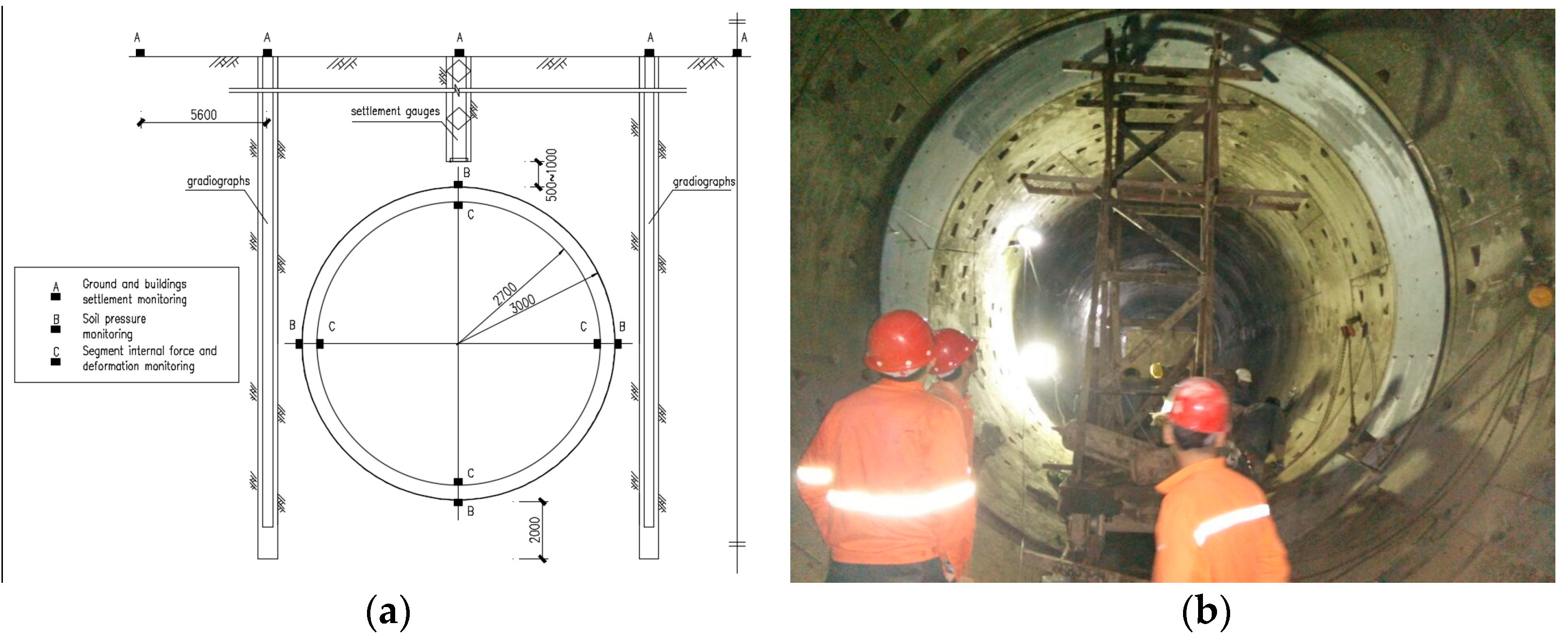
2.1. General Information

The left and right lines gradually progressed in the same direction, spaced roughly 200 m apart, using the double-line single-circle shield of this metro line. Three contact channels are positioned in the middle of the 1794 m long left line and 1782 m long right line. This period runs along the Yangtze River’s left bank or north bank. The site is situated on the Yangtze River’s submerged terrace. The field area has an open, level topography with a ground height ranging from 18.4 to 21.1 m. The strata engaged in interval crossing are (1-1) various fill soil, (1-3) silt, (3-1) clay, and (3-4) silt soil, as depicted in Figure 1.
The shield segmental liner has an outer diameter of 6.0 m and an interior diameter of 5.4 m. As seen in Figure 2, the entire ring is made up of six segments, which include one top block (K), two neighboring blocks (B1 and B2), and three standard blocks (A1, A2, and A3). The ring diameter is 1.5 m, and the section thickness is 300 mm. M27 curved bolts are used to connect the segments ring to ring and block to block, and a staggered joint assembly is used.
The shield tunneling machine accidentally broke the natural gas pipeline when advancing, and the natural gas leaked from the tail of the shield to the lining. Due to improper operation, it encountered an open fire, resulting in an explosion in the shield. In the enclosed space, the shockwave and thermal storm effect caused casualties, and equipment and structures were damaged to a certain extent, resulting in serious consequences. To avoid secondary disasters, we participated in organizing research on disposal options. As the staff of the subway company and related units actively cooperated, the emergency plan for accident rescue was carried out smoothly. Even so, the economic loss from the accident was still quite significant. After the accident, the third-party inspection unit conducted a comprehensive assessment of the safety situation of the tunnel, and each unit repaired the segments according to the inspection data and the actual situation on the spot.

2.2. Damage under Explosion

The gas explosion inside the tunnel is very likely to cause severe lining damage and, thus, threaten the stability of the tunnel [5]. According to the on-site investigation, the damage modes and mechanical responses can be mainly classified as leakage, cracks, and crushing of tunnel linings, bending and tensile failures of reinforcements, and exceeding deformation of the tunnel.

2.2.1. Leakage and Cracks

Figure 3 illustrates the 65 segments that exhibited water leakage. Of these, 21 locations had water leakage areas larger than 2000 cm2, indicating that they do not comply with secondary waterproofing criteria and must be closed. Of them, rings 1114–1118 had the most significant leak, and there might be a penetrating crack in the portion. The tunnel linings typically developed cracks as a result of the internal explosion’s rising radial expansion deformation and hoop tensile stress. However, as Figure 4 illustrates, longitudinal cracks in concrete linings were also seen adjacent to joints. There are similarities between the attitudes expressed by cracks in this study that are consistent with previous research [10,31]. Under internal explosion, the radial expansion of the tunnel ring can be attributed to the lining cracks that appeared near the impact [31]. According to an experimental study [10], the adjacent lining segments trended to be cracked at the joints due to stress concentration under internal explosion.

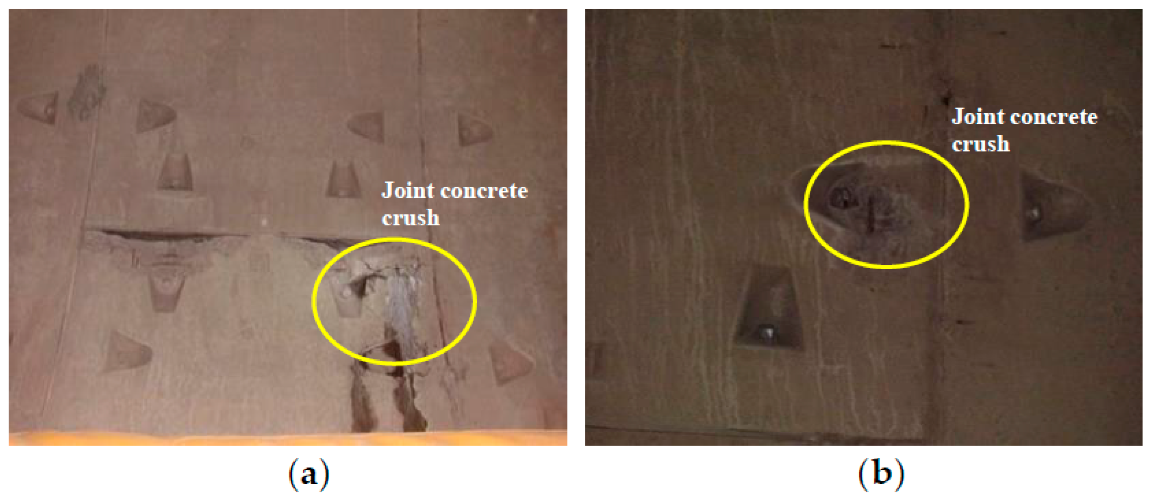
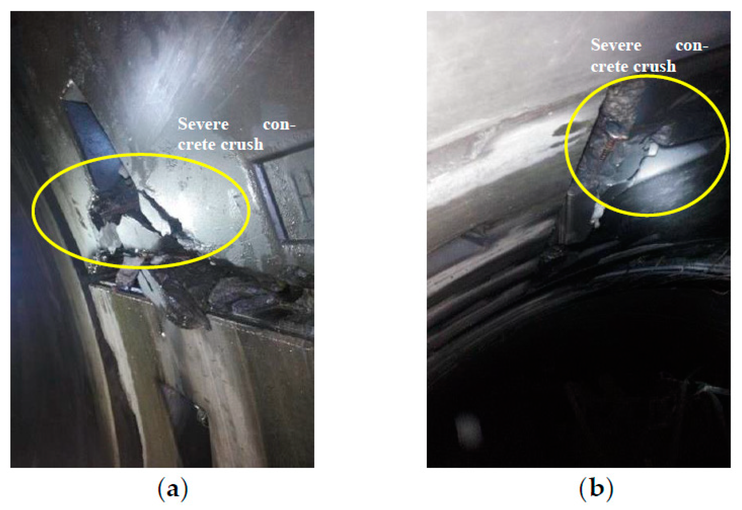
2.2.2. Concrete Crushing

According to the color of the concrete surface, the hammer reaction, the peeling condition, the strength of the concrete after the accident, as well as the shape and damage of some components on site, concrete crushing demonstrates major damage. After the accident, the measured results of dramatically decreased concrete strength showed that the surface of the concrete component was seriously deteriorated by the elevated temperature induced by the explosion [32]. The velocity of the wave blast wave generated in the left line was about 2000–3000 m/s, and the blast pressure was about 0.71–1.01 MPa as far as the highest temperature was estimated from 800 to 850 °C. As regards the surface of concrete members inspected on site, it was also found that the surface layer of some members’ collapsed and spared. The range of influence of the explosion was mainly the tunnel area of the left line of the metro line. The concrete fell off and exposed steel bars in many places, and the segments from ring 810 to ring 1121 were blackened by the smoke. The area from ring 880 to ring 1037 was also mainly blackened by the smoke. Minor damage and leakage occurred in some segments of the front section of ring 670. The concrete strength in rings 660 and 850 was slightly affected by the elevated temperature.
Because ring 733 was positioned at a turning angle, as shown in Figure 5, severe airflow caused significant concrete crush damage on the joint area. Meanwhile, the explosion had a noticeable impact on the area surrounding ring 851. This is also consistent with earlier findings [5], which demonstrate that severe crushing occurs at both the internal and external surfaces of the lining in the tunnel when it is subjected to internal explosions. Concrete crushing occurs on the interior surface as a result of the intensification of reflected compressive waves, and the crushing will progressively spread outward. As the reflected waves intensify the stress effect, the tunnel lining is crushed on the exterior surface. That may be attributed to the discrepancy of the wave impedance between the lining and surrounding soils; the compressive stress waves reflect again when the transmitted stress waves reach the interface of lining surroundings. As a result, the combined effect of the internal and external crushing of the lining may even induce the failure of the tunnel structure [5].

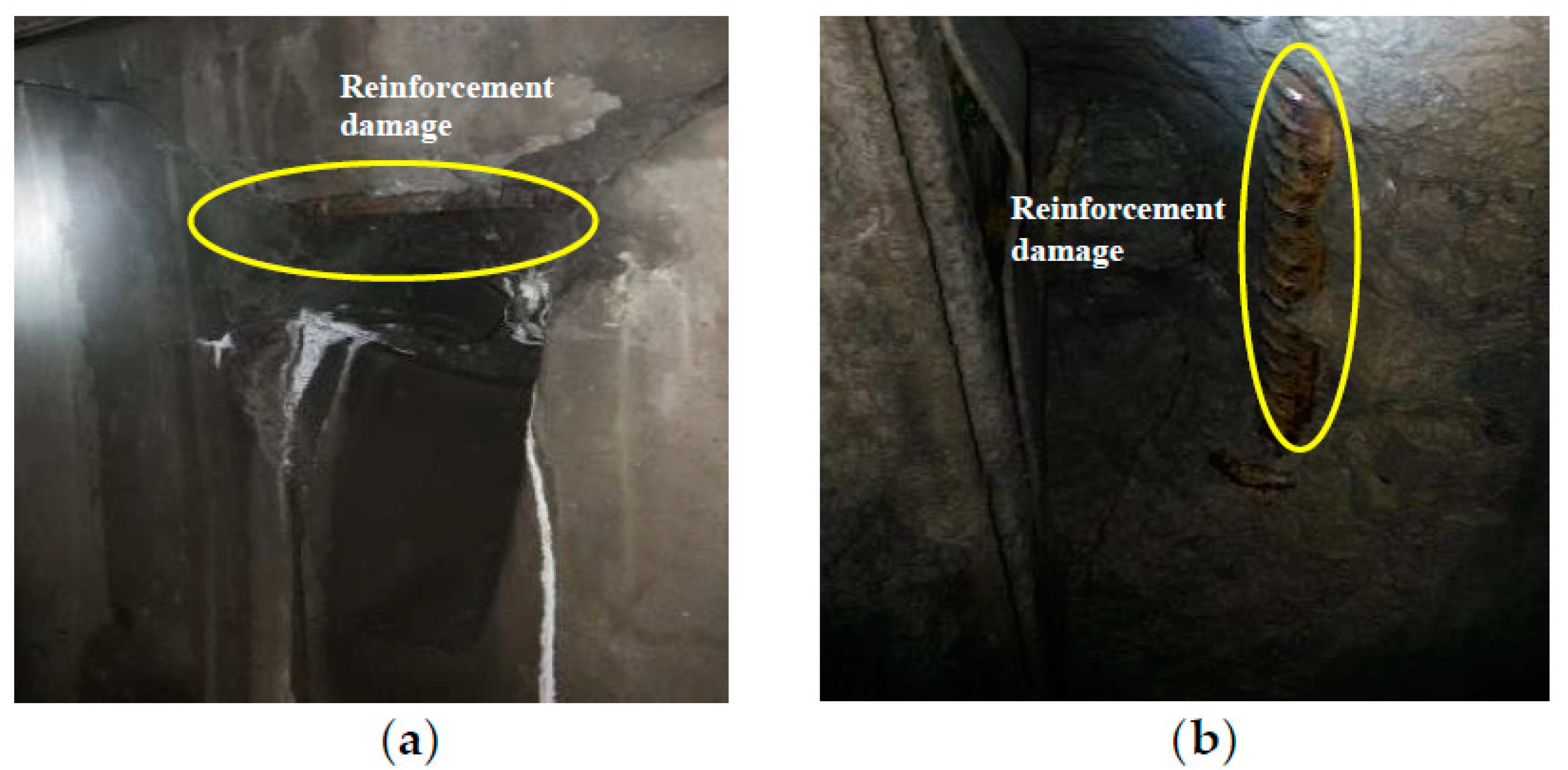
2.2.3. Damage of Reinforcement

Following the accident, the strength of the concrete and the steel reinforcement both diminished due to the combined effects of the collision and the elevated temperature. As the surface of the concrete members was impacted by the elevated temperatures and spalled off, the steel reinforcement was exposed to the effects of an explosion. The damage caused by fire to concrete segments is mostly blackening, concrete color changes, member surface cracking, local concrete spalling, concrete strength reduction, and oxidation of a portion of the steel bar. As shown in Figure 6a, under the effect of the explosion, the longitudinal and hoop reinforcements were severely damaged, especially at the junction of segments. At the same time, the hoop reinforcements were stretched to damage with the presence of longitudinal lining cracks, as shown in Figure 6b. According to the investigation report, it can be concluded that there are different degrees of damage in the reinforcement from rings 425 to 1121; however, the overall strength of the internal concrete was not affected and still satisfied the design requirements.

2.2.4. Exceeding Deformation

The segment was impacted by the explosion’s impact, as shown in Table 1, and a tiny amount of displacement occurred during the on-site assessment of the segment appearance for 30 rings. Notably, the misalignment of the segments in rings 889 and 890 at the contact channel exceeded the limit significantly. In addition, as seen in Figure 7, there was a 21 mm dislocation between ring 1118 and ring 1119. Several water leaks were also observed in the field. The union bolts revealed no symptoms of connection degradation after the segment structure was entirely constructed. According to observational research, if the exceeding deformation keeps growing, there may be a chance that the tunnel will fail. This finding broadly supports the work of other studies in this area. The uneven displacement is a significant factor in the development of the large tunnel deformation that might bring out collapse under an extensive internal explosion [3]. On the other hand, when an internal explosion occurs near the bottom lining, the top and bottom of the tunnel ring will expand outward while the two sides will deform inward [10].

2.3. Repair Measures

Based on the on-site investigation and monitoring data, the tunnel was restored following the accident, as seen in Figure 8, to reduce blast damage through passive mitigation techniques. The term “standard for restoration” refers to the pertinent technical material in the overall technical requirements for the deformation of the tunnel ring. Concrete underwent a rebound test at eighteen different places between rings 300 and 1055. The spot of deflagration was ring 1055. The direction of the hole was affected by airflow following deflagration. According to the test results, the average carbonation depth was between 1.5 and 3 mm, and the estimated strength value ranged from 42.2 to 53.6 MPa. The test results led to a reexamination of the section’s strength. As the original reinforcement and stress of the segment met the requirements, there was no need for structural strengthening. At the same time, considering that the carbonation depth is small, concrete durability meets the design requirements. As illustrated in Table 2, the repair scheme of the segment in this interval is classified as follows, considering the third-party testing data and the damage condition of a segment on site:
(1)
Rings 1–669 were not affected by the explosion; hence, they were not considered in the scope of the accident reparation.
(2)
Rings 670–764 were damaged slightly, and there was some leakage at the same time. The leakage locations were blocked, and the damaged locations were repaired according to the relevant specifications.
(3)
Rings 765–809 were also slightly damaged and burnt. Surface cleaning and essential minor repairs were required.
(4)
Rings 810–880 were damaged moderately, and there was a small amount of leakage. The repair and plugging of the damaged and leakage parts are required. As far as the overall structural deformation was concerned and the impact of the explosion was controlled, no structural strengthening measures were adopted for this section.
(5)
Rings 1114–1119 were seriously damaged, with a large area of joint leakage and the concrete crushing, which endangers the safety of the structure. After the completion of waterproof plugging and damage repair, additional reinforcement measures such as an inner steel ring should be taken.

2.4. Structural Response to Repair Measures

According to the monitoring reports, the strength of the segment was checked and calculated, and the results were in full accordance with the design requirements. At the same time, the deformation of the segment was well controlled. The current normal operation of the subway proves that the restoration plan is feasible. The sequence of repair stages can be investigated and determined based on the priority of ensuring the safety of the tunnel using structural reinforcement in future studies.

3. Numerical Modelling

As regards current analytical methods to express that the mechanical responses are not accurate enough due to the liner elastic wave assumption, most numerical studies consider the interaction between the blast wave and the structure under gas explosions. The universal numerical methods to analyze both static and dynamic responses of underground structures subjected to impact loads are mainly based on the coupled Eulerian–Lagrangian method [33,34]. In this study, concerning the mechanical behaviors of the tunnel exposed to the explosion, the ALE method was used in which the Eulerian meshes are applied to the soil, the air, and the trinitrotoluene (TNT), while the Lagrangian mesh is employed for the structure.

3.1. Geometry and Meshing

The model adopts the actual assembly of the tunnel at the explosion point of ring 1118. The dimensions and arrangement of segments and soil layers in the 3D model were the same as those in the actual engineering. As shown in Figure 9, the model involved the air, the soil, the bursting point, and the assembled tunnel segments with appropriate boundary conditions. To decrease the stress wave reflection, the non-reflection boundaries were applied on the two lateral sides and the bottom side of the soil, as shown in Figure 9. The base was fixed in all directions to present the surrounding soil, and a free boundary condition was set for the upper surface [33]. As can be seen in Figure 10, the segmental ring is assembled by six segments, i.e., K, B1, B2, A1, A2, and A3, as shown also in Figure 2. The top block is left at the top, and the explosion point is in the middle and lower part of the segmental lining, which is close to the actual situation.

3.2. Material Model

3.2.1. Soil

While geotechnical materials are heterogeneous, discontinuous, anisotropic rheological media with many flaws, the primary focus of this numerical research is how the explosion affects shield segments. Thus, the elastic model represents the soil. As illustrated in Figure 1, the geological survey report states that it is separated into four soil strata. The silt, clay, silt soil, and various fill soils have elastic modules of 0.6 MPa, 1 MPa, 0.8 MPa, and 2.4 MPa, respectively. Every soil layer has a Poisson’s ratio of 0.3.

3.2.2. Tunnel

Yang et al. [35] previously reported that the tunnel was modeled using (MAT_plastic_kinematic). Previous research widely used this model to simulate the tunnel structure subjected to explosion [35]. It is also accessible as a very effective model for the beam, shell, or solid elements. Based on the idea of comparable stiffness, the concrete and reinforcement are regarded as a whole. C50 constructed the lining concrete. The Young’s modulus is 34.5 GPa, and the Poisson’s ratio is 0.2. On the other hand, the CONTACT_AUTOMATIC_SINGLE_SURFACE contact was employed to define the interface between the segments [33,36]. The curved bolts were simulated as a chain of straight beam elements. Meanwhile, the bolts were modeled as the discrete elements immersed in the segment meshes using the CONSTRAINED_LAGRANGE_IN_SOLID coupling between the Lagrangian meshes and Eulerian meshes [33].

3.2.3. TNT

As a widely applied model in engineering calculations, the Jones–Wilkens–Lee (JWL) equation of state (EOS) describes the pressure released by the fuel energy during the explosion. The pressure is defined by the JWL EOS, as follows (Xie et al.) [37]:
p = A 1 w R 1 V e R 1 V + B 1 w R 2 V e R 2 V + w E V
where V is the relative volume of the explosive product, E is the internal energy per unit volume, and A, B, R1, R2, ω are the empirically derived constants for the explosive [36]. The explosive charge weight was modeled using (MAT_high_explosive_burn). Table 3 gives the parameters used for TNT [33]. According to the damage degree from the detection after the accident, the TNT equivalent was determined based on the maximum estimated overpressure (1.01 MPa). The details about how the TNT equation of state parameters was derived can also be checked in [33].

3.2.4. Air

With a linear polynomial equation of state, the air was modeled as [MAT_Null] [36]. The air pressure can be written as Equation (2) [34]:
p = ( γ 1 ) E V
where γ is the adiabatic constant for air behaving as an ideal gas, V (m3) is the volume of gas, and E (J) is the initial internal energy per volume.

3.3. Numerical Solver

As the ALE can handle problems with greater deformations of the mesh and provide greater resolution than other methods, an ALE solver is employed to assess the finite element model. The ALE Multi-Material formulation can also adopt a mixture of different materials in each mesh. Therefore, the soil, the air, and TNT are modeled as Eulerian meshes, while the tunnel structure is modeled using a Lagrangian mesh. Meanwhile, the coupling between the Eulerian meshes and Lagrangian meshes, i.e., Constrained_ Lagrange_In_Solid, is used as a penalty factor to govern the penetration of the explosive air volume fraction into the structure [36]. Furthermore, these modeling sets and rules have also been adopted in other studies [33,35,38,39,40]. Hence, the current study is considered to be reliable for studying the mechanical responses of a shield tunnel.

4. Results and Discussion

4.1. Gas Propagation

The initial set of analyses looked at how the gas explosion spread. Figure 11 depicts the preliminary analysis of explosive gas propagation within the tunnel in different timeframes. The gas propagation traveled further from the tipping point to the surrounding space in the tube as the severity of the explosion increased. The gas propagation grows rather swiftly and steadily at the start of the explosion. The gas propagation (GP) is accompanied by pressure produced by the chemical energy, especially within the first 0.3 ms, and a considerable variation in the range of explosive gas is noticed. Following the addition of an explosion, from 0.5 ms to 2 ms, a significant increase in the gas propagation is recorded. Surprisingly, only a minority of explosive gas propagates from 2 ms to 4 ms. According to the accident investigation in Section 2.2, the single most striking observation to emerge from the data comparison is that the influenced region of the tunnel accords with the damage situation. From 4 ms to 5 ms, with the peak pressure, the responses of the shield tunnel under the gas explosion load should be emphasized to verify the deformation characteristics of structures. The next section of the analysis was concerned with the development of principal stress and deformation. The maximum pressure of 1 MPa accords with the estimated value from detection after the accident based on the damage degree.

4.2. Development of Principal Stress

The results obtained from the preliminary analysis of the maximum principal stress variation in the tunnel during explosion versus time are presented in Figure 12.
From the curves, we can see that the compressive stress results in the highest value of 16.5 MPa, and the tensile stress results in the highest value of 5 MPa. There is a clear trend of decreasing for the compressive stress after 2.5 ms and for the tensile stress after 2 ms, as can be seen from Figure 12. Closer inspection of the figure shows that there is a significant time difference of 0.5 ms between the two groups.

4.3. Explosion Influence on the Joints

The results obtained from the preliminary analysis of maximum deformation variation in the tunnel and Joint A1-A2 and Joint A2-A3 during explosion versus time are presented in Figure 13. The general development and the maximum value of the results are comparable with the on-site investigation. According to the data in Figure 13, it is apparent that the length of impact time at the initial stage is 1.5 ms. At 3 ms, the plastic damage first occurs in the joints due to the stress concentration under gas explosion loads. When the gas explosive pressure propagates and increases, the maximum convergence deformation increases sharply and approaches 9 mm. Under the gas explosion load with peak pressure, the maximum convergence deformation of the tunnel is 15 mm and the openings of Joints A2-A3 and A1-A2 are 5 mm and 9 mm, respectively. That is to say, severe damage and cracks can be found in segments and joints. The bottom line in Figure 11 shows that the lower-right corner is the most immediate impacted position followed by left and top segments. The cracks and crushing of the concrete segmental joints reduce the constraint of segments, which makes the overall displacement of the tunnel develop quickly.
Explosion time history curves of joint openings are depicted in Figure 14. The general development and the maximum value of the results are comparable with the on-site investigation. From this figure, it can be seen that the displacement development of different joints is manifold. A closer inspection of the figure shows that 2 ms is the significant turning time point. After this point, the displacement of Joints B2-A3 and A2-A1 fluctuates, while there is a clear trend of increasing for Joints A1-B1, B1-K, and K-B2. Therefore, there has been continual growth in the overall deformation of the tunnel ring after the explosion. What can be seen is the phenomenal peak of Joints A3-A2 and A2-A1. From these data, we can see that the displacement of Joint A2-A1 reaches more than 3 mm, while Joint K-B2 only results in the highest value of 0.015 mm. This also accords with the explosive gas propagation process in Figure 11. These results may be taken to indicate that the longer-term impact can be assessed on the engineering scale.
With the increase in overpressure, cracks appear in the joints and subsequently extend along the joints. As shown in Figure 5, cracks occur in the area of the joint handhole. Cracks can be found in the joint area of the neighboring segment experiencing slight damage in the joints. And typical flexure failure of the reinforcement can be observed, as presented in Figure 6. The reinforcement in the joints ruptures under the destructive load, and the damage to the neighboring segments can be observed. These results show that the peak pressure induced the by gas explosion loads significantly governs the response of shield tunnels. It can also be concluded that the segmental joints towards the explosive granaries are quite vulnerable due to the stress concentration and the overall deformation. Taken together, these results suggest that there is a strong association between the joint deformation and the tunnel’s overall convergence. In practical engineering, additional protective measures that release the stress in the joints and improve the resistance of segments should be further taken into consideration.

5. Conclusions

In this paper, an explosion accident of a shield segmental lining under construction due to the destruction of the natural gas pipelines by the shield tunneling machine was discussed, in which the structure failure characteristics during the explosion and the structure repair method after the explosion were investigated. This study also used the finite element approach with the ALE technique to replicate the explosion scenario to explore the gas explosion within the tunnel during the accident. The following conclusions can be taken from the accident investigation and numerical analysis:
(1)
According to the site investigation, the tunnel structure under the explosion impact suffers from various damage, e.g., the leakages, cracks, and crushing of tunnel linings, bending and tensile failures of reinforcements, and exceeding deformation. It should be noted that the longitudinal and circumferential joints of the shield tunnel structure are more vulnerable under blast loads due to their relatively weak stiffness. Currently, assessment methods of shield tunnels have different limitations in quantifying the damage on the junctions of the structural members under blast loading. Therefore, there remains a requirement for developing reliable assessment methods to be recommended for further study.
(2)
The segment lining ring exhibits normal bending behavior under gas explosion loads. The gas propagation grows rather swiftly and steadily at the beginning of the explosion. Because of the concentration of stress under gas explosion loads, joints sustain the most severe damage as the gas explosive pressure increases. The maximum convergence deformation increases significantly as a result of the concrete segmental joints’ crushing and cracking, which lessens the segments’ constraint. Following the explosion, the tunnel ring’s total distortion will, likewise, continue to develop.
(3)
A number of repair options for the damaged tunnel have also been studied. According to monitoring data and on-site research, the damaged tunnel was restored mostly through passive methods to limit blast damage. However, most of these reliable methods are still under evaluation in engineering practice due to the high cost and immature technologies transferred from general tunnel reinforcement. As a result, there is still a significant research need for more effective and low-cost tunnel repair procedures following the explosion catastrophe.
This study was limited by the absence of other key variables of tunnels, e.g., the buried depth, cross-sectional dimension, etc., were not fully investigated and are recommended for further study. Notwithstanding this limitation, this study provides new insights into blast responses of tunnels under a real accident and certainly adds to our understanding of post-explosion repair. Further investigation and experimentation into shield tunnel structures in blast loads would help us to establish a greater degree of accuracy regarding this matter. Further parametric studies and validation works would be meaningful to improve the availability of the research results. Surveys and investigations on the stability and destruction of the segments and joints are also strongly recommended.

Author Contributions

Y.S.: Writing—original draft, formal analysis, funding acquisition. S.S.: Investigation, data curation, software. W.S.: Supervision, validation. L.Z.: Funding acquisition. Z.H.: Writing—review and editing, data curation, supervision. All authors have read and agreed to the published version of the manuscript.

Funding

This research was supported by the Fundamental Research Funds for the Central Universities, CHD (Research Center of Highway Large Structure Engineering on Safety, Ministry of Education, Grants No. 300102213527), Natural Science Foundation of Chongqing, China (No. CSTB2023NSCQ-MSX0808), and National Natural Science Foundation of China (Grants No. 52090083, 52008308, 52108381).

Data Availability Statement

Some or all data, models, or codes generated or used during the study are available from the corresponding author on request. The data are not publicly available due to privacy.

Conflicts of Interest

The authors declare no conflict of interest.

References

  1. He, S.Y.; Su, L.J.; Fan, H.B.; Ren, R. Methane explosion accidents of tunnels in SW China. Geomat. Nat. Hazards Risk 2019, 10, 667–677. [Google Scholar] [CrossRef]
  2. Yan, D.; Wu, Q.; Li, T.Y.; Ren, Y.Y. Investigation and Analysis on the Explosion Accident in the Mountain Tunnel. J. Eng. Sci. Technol. Rev. 2019, 12, 152–159. [Google Scholar] [CrossRef]
  3. Li, Z.P.; Wu, S.C.; Cheng, Z.Q.; Jiang, Y.B. Numerical Investigation of the Dynamic Responses and Damage of Linings Subjected to Violent Gas Explosions inside Highway Tunnels. Shock Vib. 2018, 2018, 1–20. [Google Scholar] [CrossRef]
  4. Kang, N. Study on a Comprehensive Model for Fire Risk Assessment in Road Tunnel Operation. Ph.D. Thesis, China University of Mining and Technology, Beijing, China, 2019. [Google Scholar]
  5. Cheng, R.S.; Chen, W.S.; Hao, H.; Li, J.D. A state-of-the-art review of road tunnels subjected to blast loads. Tunn. Undergr. Space Technol. 2021, 112, 103911. [Google Scholar] [CrossRef]
  6. Chen, H.L.; Jin, F.N.; Fan, H.L. Elastic responses of underground circular arches considering dynamic soil-structure interaction: A theoretical analysis. Acta Mech. Sin. 2013, 29, 110–122. [Google Scholar] [CrossRef]
  7. Gao, M.; Wang, Y.; Gao, G.Y.; Yang, J. An analytical solution for the transient response of a cylindrical lined cavity in a poroelastic medium. Soil Dyn. Earthq. Eng. 2013, 46, 30–40. [Google Scholar] [CrossRef]
  8. Li, C.J.; Li, X.B. Influence of wavelength-to-tunnel-diameter ratio on the dynamic response of underground tunnels subjected to blasting loads. Int. J. Rock Mech. Min. Sci. 2018, 112, 323–338. [Google Scholar] [CrossRef]
  9. Ming, T.; Li, Z.W.; Cao, W.Z.; Li, X.B.; Wu, C.Q. Stress redistribution of dynamic loading incident with arbitrary waveform through a circular cavity. Int. J. Numer. Anal. Methods Geomech. 2019, 43, 1279–1299. [Google Scholar]
  10. Zhao, Y.T.; Chu, C.; Yi, Y.J. Study on an engineering measure to improve internal explosion resistance capacity of segmental tunnel lining structures. J. Vibroeng. 2016, 18, 2997–3009. [Google Scholar] [CrossRef]
  11. Liu, H.B.; Nezili, S. Centrifuge Modeling of Underground Tunnel in Saturated Soil Subjected to Internal Blast Loading. J. Perform. Constr. Facil. 2016, 30, 06015001. [Google Scholar] [CrossRef]
  12. Prochazka, P.; Jandeková, D. Effect of explosion source location on tunnel damage. Int. J. Prot. Struct. 2020, 11, 448–467. [Google Scholar] [CrossRef]
  13. Han, Y.Z.; Zhang, L.; Yang, S.R. Soil-tunnel Interaction under Medium Internal Blast Loading. Procedia Eng. 2016, 143, 403–410. [Google Scholar] [CrossRef]
  14. Yu, H.T.; Wang, Z.B.; Yuan, Y.; Li, W.T. Numerical analysis of internal blast effects on underground tunnel in soils. Struct. Infrastruct. Eng. 2015, 12, 1090–1105. [Google Scholar] [CrossRef]
  15. Tiwari, R.; Chakraborty, T.; Matsagar, V. Dynamic Analysis of Tunnel in Soil Subjected to Internal Blast Loading. Geotech. Geol. Eng. 2017, 35, 1491–1512. [Google Scholar] [CrossRef]
  16. Prasanna, R.; Boominathan, A. Finite-Element Studies on Factors Influencing the Response of Underground Tunnels Subjected to Internal Explosion. Int. J. Geomech. 2020, 20, 04020089. [Google Scholar] [CrossRef]
  17. Buonsanti, M.; Leonardi, G. 3-D simulation of tunnel structures under blast loading. Arch. Civ. Mech. Eng. 2013, 13, 128–134. [Google Scholar] [CrossRef]
  18. Kristoffersen, M.; Minoretti, A.; Børvik, T. On the internal blast loading of submerged floating tunnels in concrete with circular and rectangular cross-sections. Eng. Fail. Anal. 2019, 103, 462–480. [Google Scholar] [CrossRef]
  19. Wang, S.P.; Li, Z.; Fang, Q.; Yan, H.C.; Chen, L. Performance of utility tunnels under gas explosion loads. Tunn. Undergr. Space Technol. 2021, 109, 103762. [Google Scholar] [CrossRef]
  20. Lee, W.F.; Ishihara, K. Forensic diagnosis of a shield tunnel failure. Eng. Struct. 2010, 32, 1830–1837. [Google Scholar] [CrossRef]
  21. Zhou, L.; Yan, Z.G.; Shen, Y.; Guan, L.X. Experimental study on the effect of ductile-iron panel stiffness on mechanical properties of segmental joints of shield tunnels. Undergr. Space 2022, 7, 1056–1067. [Google Scholar] [CrossRef]
  22. Zhou, L.; Shen, Y.; Guan, L.X.; Yan, Z.G.; Sun, W.; Li, Y.L. Full-scale experiment for segmental linings of deep-buried shield tunnels bearing high inner water pressure: Comparison of mechanical behaviors of continuous- and stagger-jointed structures. Undergr. Space 2023, 8, 252–266. [Google Scholar] [CrossRef]
  23. Zheng, G.; Cui, T.; Cheng, X.S.; Diao, Y.; Zhang, T.Q.; Sun, J.B.; Ge, L.B. Study of the collapse mechanism of shield tunnels due to the failure of segments in sandy ground. Eng. Fail. Anal. 2017, 79, 464–490. [Google Scholar] [CrossRef]
  24. Shen, S.; Lv, H.X.; Ma, S.L. Damage Detection and Evaluation for an In-Service Shield Tunnel Based on the Monitored Increment of Neutral Axis Depth Using Long-Gauge Fiber Bragg Grating Sensors. Sensors 2019, 19, 1840. [Google Scholar] [CrossRef] [PubMed]
  25. Zhang, T.; Zhang, Y.; Zhu, H.H.; Yan, Z.G. Experimental investigation and multi-level modeling of the effective thermal conductivity of hybrid micro-fiber reinforced cementitious composites at elevated temperatures. Compos. Struct. 2021, 256, 112988. [Google Scholar] [CrossRef]
  26. Shen, Y.; Ling, J.X.; Wang, W.Z.; Zhu, H.H.; Yan, Z.G. 3D numerical investigation on the response of shield tunnel under combined effects of fire and structural loading. Tunn. Undergr. Space Technol. 2022, 128, 104659. [Google Scholar] [CrossRef]
  27. Kiriyama, K.; Kakizaki, M.; Takabayashi, T.; Hirosawa, N.; Takeuchi, T.; Hajohta, H.; Yano, Y.; Imafuku, K. Structure and construction examples of tunnel reinforcement method using thin steel panels. Nippon. Steel Tech. Rep. 2005, 92, 45–50. [Google Scholar]
  28. Liu, D.J.; Wang, F.; Zhang, D.M.; Duan, K. Interfacial stresses of shield tunnel strengthened by a thin plate at the inner surface. Tunn. Undergr. Space Technol. 2019, 91, 103021. [Google Scholar] [CrossRef]
  29. Liu, D.J.; Wang, F.; Hu, Q.F.; Huang, H.W.; Zuo, J.P.; Tian, C.; Zhang, D.M. Structural responses and treatments of shield tunnel due to leakage: A case study. Tunn. Undergr. Space Technol. 2020, 103, 103471. [Google Scholar] [CrossRef]
  30. Zhang, D.M.; Zhai, W.Z.; Huang, H.W.; Chapman, D. Robust retrofitting design for rehabilitation of segmental tunnel linings: Using the example of steel plates. Tunn. Undergr. Space Technol. 2019, 83, 231–242. [Google Scholar] [CrossRef]
  31. Krone, E. Internal Blast Loading of Submerged Floating Tunnels in Concrete. Master’s Thesis, Norwegian University of Science and Technology, Trondheim, Norway, 2018. [Google Scholar]
  32. Teles, D.V.C.; Oliveira, M.C.; Amorim, D.L.N.F. A simplified lumped damage model for reinforced concrete beams under impact loads. Eng. Struct. 2020, 205, 110070. [Google Scholar] [CrossRef]
  33. Koneshwaran, S. Blast Response and Sensitivity Analysis of Segmental Tunnel. Ph.D. Thesis, Queensland University of Technology, Brisbane City, QLD, Australia, 2014. [Google Scholar]
  34. Mussa, M.H.; Mutalib, A.A.; Hamid, R.; Naidu, S.R.; Radzi, N.A.M.; Abedini, M. Assessment of damage to an underground box tunnel by a surface explosion. Tunn. Undergr. Space Technol. 2017, 66, 64–76. [Google Scholar] [CrossRef]
  35. Yang, Y.B.; Xie, X.Y.; Wang, R.L. Numerical simulation of dynamic response of operating metro tunnel induced by ground explosion. J. Rock Mech. Geotech. Eng. 2010, 2, 373–384. [Google Scholar]
  36. LS-DYNA. Keyword User’s Manual; Livermore Software Technology Corporation: Livermore, CA, USA, 2007. [Google Scholar]
  37. Xie, L.X.; Lu, W.B.; Zhang, Q.B.; Jiang, Q.H.; Wang, G.H.; Zhao, J. Damage evolution mechanisms of rock in deep tunnels induced by cut blasting. Tunn. Undergr. Space Technol. 2016, 58, 257–270. [Google Scholar] [CrossRef]
  38. Qian, H.; Zong, Z.; Wu, C.; Li, J.; Gan, L. Numerical study on the behavior of utility tunnel subjected to ground surface explosion. Thin-Walled Struct. 2021, 161, 107422. [Google Scholar] [CrossRef]
  39. Roy, T.; Matsagar, V. Mechanics of damage in reinforced concrete member under post-blast fire scenario. Structures 2021, 31, 740–760. [Google Scholar] [CrossRef]
  40. Huang, Z.K.; Ning, C.L.; Zhang, D.M.; Huang, H.W.; Zhang, D.M.; Argyroudis, S. PDEM-based seismic performance evaluation of circular tunnels under stochastic earthquake excitation. In Georisk: Assessment and Management of Risk for Engineered Systems and Geohazards; Taylor & Francis: Abingdon, UK, 2023; pp. 1–13. [Google Scholar]
Figure 1. General information of the explosion accident in the tunnel.
Buildings 14 00056 g001
Figure 2. The layout of the segmental ring and the explosion point.
Buildings 14 00056 g002
Figure 3. Leakage induced by explosion: (a) ring 671; (b) ring 836.
Buildings 14 00056 g003
Figure 4. Cracks caused by explosion: (a) ring 1409; (b) ring 1116.
Buildings 14 00056 g004
Figure 5. Joint concrete crush damaged by explosion: (a) ring 733; (b) ring 851.
Buildings 14 00056 g005
Figure 6. Damage of the reinforcements: (a) longitudinal reinforcement; (b) hoop reinforcement.
Buildings 14 00056 g006
Figure 7. Severe concrete crush induced by explosion: (a) ring 1118; (b) ring 1119.
Buildings 14 00056 g007
Figure 8. The layout of tunnel monitoring: (a) routine monitoring; (b) post-accident monitoring and reparation.
Buildings 14 00056 g008
Figure 9. Geometry of the profile of the numerical model.
Buildings 14 00056 g009
Figure 10. Layout of longitudinal joints and burst point: (a) cross-section; (b) isometric diagram.
Buildings 14 00056 g010
Figure 11. Explosive gas propagated within the tunnel at different times: (a) 0 ms; (b) 0.1 ms; (c) 0.2 ms; (d) 0.3 ms; (e) 0.5 ms; (f) 1 ms; (g) 2 ms; (h) 4 ms; (i) 5 ms.
Buildings 14 00056 g011
Figure 12. Maximum principal stress variation in the tunnel during explosion versus time.
Buildings 14 00056 g012
Figure 13. Maximum deformation variation of the tunnel and key joints during explosion versus time.
Buildings 14 00056 g013
Figure 14. Explosion time history curve of joint openings: (a) Joint B2-A3; (b) Joint A3-A2; (c) Joint A2-A1; (d) Joint A1-B1; (e) Joint B1-K; (f) Joint K-B2.
Buildings 14 00056 g014aBuildings 14 00056 g014b
Table 1. The detection result of tunnel interval impacted by the explosion.
Measure TypeValueNumberPercentage
Circumferential joint opening (mm)7310%
Longitudinal dislocation (mm)45 mm123%
21 mm1
<12 mm5
Table 2. Measures for tunnel after the explosion.
SectionNumber of RingsSeverityMeasure
1–669669No influenceNone
670–76495Slightly damaged and no burntMinor repair and local reinforce
765–80944Slightly damaged and burntSurface cleaning and local reinforce
810–88071Slightly damaged and slightly burntSurface cleaning and local reinforce
880–1113234Moderately damaged and burntSurface cleaning and local reinforce
1114–11196Severe damaged and burntMajor repair
Table 3. Parameters of the explosive state equation [33].
ρ (kg/m3)v (m/s)PCJ (GPa)A (GPa)B (GPa)R1R2wE0 (kJ/m3)V0
16007000213753.74.150.90.356 × 1061.0
Disclaimer/Publisher’s Note: The statements, opinions and data contained in all publications are solely those of the individual author(s) and contributor(s) and not of MDPI and/or the editor(s). MDPI and/or the editor(s) disclaim responsibility for any injury to people or property resulting from any ideas, methods, instructions or products referred to in the content.

