Article

Application of Fuzzy-ISM-MICMAC in the Risk Analysis Affecting Swivel Bridge Construction Spanning Existing Railway Lines: A Case Study

1
Department of Engineering Management, School of Civil Engineering, Central South University, Changsha 410075, China
2
Shandong Railway Investment Holding Group Co., Ltd., Jinan 25000, China
*
Author to whom correspondence should be addressed.
Buildings 2024, 14(1), 52; https://doi.org/10.3390/buildings14010052
Submission received: 13 October 2023 / Revised: 12 December 2023 / Accepted: 21 December 2023 / Published: 24 December 2023
(This article belongs to the Special Issue The Impact of Construction Projects and Project Management on Society)

Abstract

:
Swivel bridge construction (SBC) technology has significant advantages in building bridges that span existing railway lines (ERLs), but it also entails complex risks from ‘skylight’ windows and railway boundaries. A notable challenge is the relationships and interdependencies among these risks, which collectively increase safety hazards through mutual influence. Prior research has typically focused on mitigating the risks inherent in particular tasks or operations, with less emphasis on the risks from interdependencies. A novel framework was developed to explore this research gap by integrating fuzzy logic, interpretive structural modeling (ISM) and the cross-impact matrix multiplication applied to classification (MICMAC) approach (Fuzzy-ISM-MICMAC) to investigate the relationships and interdependencies among the risks of SBC spanning ERLs and the critical points of risk control. Furthermore, the data collected from a literature review, a case analysis and expert interviews resulted in 28 risk factors. Then, the application of ISM distilled complex risk relationships into a clear, multilevel hierarchy, accurately illustrating the complex interrelationships among risk factors. Combined with MICMAC analysis, the research findings indicate that preliminary works such as the selection of construction technology, scheme design, construction rehearsal and the provision of safety facilities are essential for preventing risks in SBC spanning ERLs. We applied these findings to the double T-structure swivel construction of the Xiaojizhuang Bridge, where its practicality and efficiency were thoroughly tested and validated. This research’s critical contribution is identifying, clarifying and visualizing the interrelationships of the complex risk factors of SBC spanning ERLs and providing specific solutions for safety management in similar bridge construction projects. The research results and risk control recommendations offer valuable insights for managing other swivel bridge construction risks.

1. Introduction

The evolution of swivel bridge construction (SBC) technology has achieved a significant level of maturity [1]. There is a growing trend toward the incorporation of multi-thousand-ton, exceptionally long cantilevered swivel bridges encompassing highway and railway infrastructure. SBC technology is becoming widespread [2,3,4], and the benefits of swivel technology in complex constructions are increasingly being recognized [5]. SBC proves indispensable under such circumstances, showcasing its unparalleled efficacy [6]. This construction method, unlike traditional railway bridge buildings, involves greater risks due to two main factors. First, the “skylight” window limits the available construction time. Second, the space for construction activities is restricted by the existing railway’s boundaries, complicating the task while ensuring ongoing traffic flow. Therefore, it is crucial to minimize disturbances to existing railway infrastructure and mitigate inherent safety hazards in the construction process [7]. How to assess and control the risk factors affecting SBC spanning ERLs effectively is a difficult problem that needs to be solved.
Before initiating SBC spanning ERLs, conducting a systematic and comprehensive exploration is imperative to understanding the risk factors associated with rotary construction thoroughly [8]. Existing research mainly targets bridge rotation technologies [9,10,11,12], with standards focusing on technical essentials [1,13]. Safety protocols are typically focused on mitigating the risks inherent in particular tasks or operations [14,15]. Some risks are interdependent and have multiple effects [16,17], and it becomes cumbersome for the project decision makers to trace the actual source of these risks [18]. However, a critical aspect remains unaddressed: the certain interdependencies among the risks, which collectively increase safety hazards through their mutual influence. Surprisingly, this has received limited attention in prior research.
It is crucial to analyze the interrelationships among these risk factors and categorize them into hierarchical levels. The formulation of precise and targeted control measures becomes necessary. This methodical and rigorous approach plays a pivotal role in providing substantial support for the safe execution of SBC spanning ERLs.
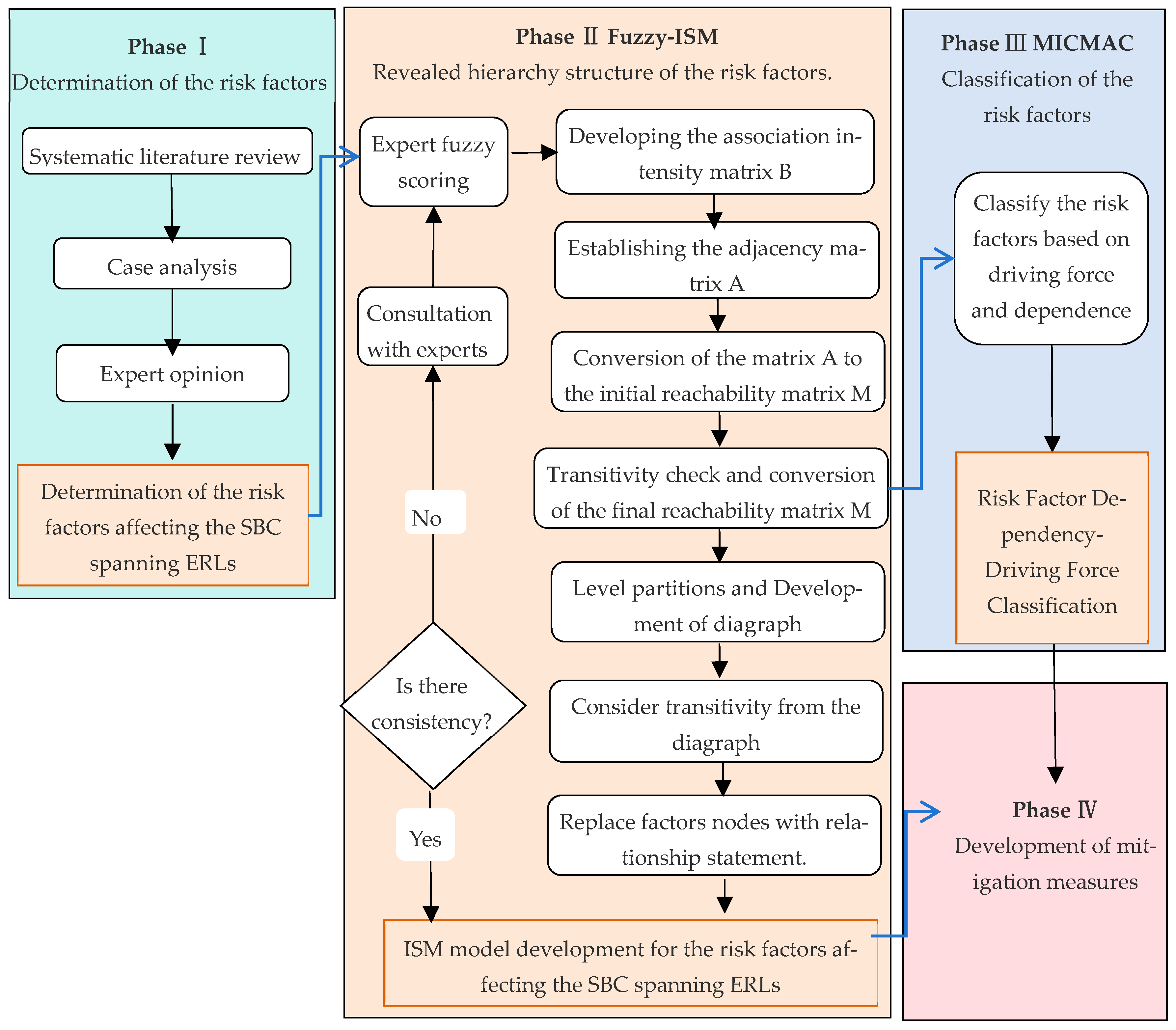
This study seeks to address this research gap by employing fuzzy logic, interpretive structural modeling (ISM) and the cross-impact matrix multiplication applied to classification (MICMAC) approach (Fuzzy-ISM-MICMAC) to investigate the relationships and interdependencies among these risks of SBC spanning ERLs and the critical points of risk control. The integration of fuzzy logic with ISM not only mitigates the subjectivity associated with expert judgments but also amplifies the adaptability of the model [19]. Combining the MICMAC method to hierarchically classify and determine the attributes of risk factors affecting SBC spanning ERLs significantly streamlines the analysis and assessment of pertinent risk factors [20]. The process involves three key steps: (1) determining the risk factors, (2) delineating the interrelationships and hierarchical structure of risk factors and (3) proposing corresponding optimization strategies.
This paper is organized as follows: Section 2 reviews the relevant literature on swivel bridge construction, the risk analysis of SBC and the inventory of risk factors aligned with the Fuzzy-ISM-MICMAC method. Section 3 introduces the research flowchart, detailing how the Fuzzy-ISM-MICMAC research methodology is implemented. Section 4 involves the identification of risk factors affecting SBC spanning ERLs and encompasses the establishment of an ISM model and MICMAC analysis. Finally, Section 5 and Section 6 provide a discussion of our findings and conclude the paper.

2. Literature Review

2.1. Swivel Bridge Construction

Swivel construction, first applied in the 1940s and known as the central bearing rotation method or the rotating deck construction method [21], provides an optimal construction method for building bridges. This method enables the construction of a bridge’s superstructure away from traffic, and it enables rotating it into its designated position through a swivel system. SBC often separates the main span of bridges into two sections, either parallel or perpendicular to the obstacle, and then rotates the superstructure into its final position for joining [22,23]. Usually, this method is used to cross obstacles such as rivers, valleys and railways, where assembling on temporary supports is impossible [24]. When contrasted with in situ casting and suspended basket building methods [21], SBC boasts several advantages [2,6]. It minimizes traffic disruption, enhances construction safety, shortens project timelines and optimizes costs [25,26,27]. Consequently, this method has become popular as a fast-track approach for building bridges in urban areas and over railways [28], and it has been effectively utilized in building hundreds of various types of bridges [26], including continuous girders [23], arches [29,30] and cable-stayed bridges [31,32], across North America, Australia, Europe and Asia.
The construction of swivel bridges has exhibited two clear trends: (1) Their use has become extensive following years of evolution. (2) Prior to the 2000s, the swivel tonnage was typically small, but it experienced a significant jump by around 2000, escalating from around 5.0 × 10⁶ kg to 1.5 × 10⁷ kg and even exceeding 4.6 × 107 kg by 2019 [2]. The escalation in swivel tonnage has introduced considerable challenges to the design and construction of swivel bridges, demanding innovative solutions and enhancements [26].
Furthermore, railways’ operational mileage in China increased from 98,000 km in 2012 to 155,000 km in 2022, during which high-speed rails expanded from 9000 km to 42,000 km. Against this backdrop, a substantial number of new routes are being constructed, and there are numerous instances of construction occurring adjacent to existing lines. Consequently, the number of bridge projects spanning existing railway lines is progressively increasing. Effectively employing swivel technology in bridge construction can efficiently address the conflict between building new bridges and operating existing railways [33].
Numerous scholarly studies have been conducted regarding the construction technology of bridge swiveling over ERLs. The primary focus of these studies includes the construction precision of swiveling large-span T-frame bridges [34]; the design and construction plans for the simultaneous rotation of a short-span, dual-span T-frame bridge [9]; a theoretical inquiry into the stability against toppling of heavy-tonnage T-frame bridges [10]; the technology for monitoring stress and deformation used on a T-frame bridge during its rotation [11]; the construction technology involved in the simultaneous rotation of both spans in T-frame bridges [12]; and an accurate model for predicting the condition of bridge decks developed to ensure their structural integrity [35]. However, existing research has primarily focused on rotary construction technology, with less emphasis on risk management for bridges spanning ERLs [2,36]. Therefore, assessing and controlling the risk factors impacting SBC spanning ERLs presents a complex challenge that requires thorough investigation.

2.2. Risk Analysis in Swivel Bridge Construction

Various methods are employed to analyze construction risks. A path analysis develops a project phase-based contingency adjustment framework, capturing the linkage effects of factors throughout the project [17]. A combined fuzzy DEMATEL-fuzzy ANP model assesses risk interrelations [37], and the ISM method creates a hierarchical model for fall risks. Integrated with the analytic hierarchy process (AHP), this approach elucidates the causal mechanisms underlying accidents involving falls from heights [38]. The fuzzy interpretive structural modeling method was utilized to construct a multi-level hierarchical structure of critical influencing factors. Based on this framework, an analysis was conducted to dissect the causal mechanisms contributing to safety incidents in the rotary construction of bridges spanning existing railway lines [7]. YANG employed the interval-valued analytic hierarchy process method to study safety risk management in constructing T-girder rotary bridges [39]. The ISM model and MICMAC method were utilized to classify safety risk factors in construction hierarchically. Based on the elucidation of interconnections and causal mechanisms, tailored risk management strategies were devised for distinct risk factor categories [40].
In this study, we employed manual statistical methods to examine the literature on risk factors impacting SBC spanning ERLs to identify and extract relevant risk factors. Databases such as Web of Science, Elsevier and CNKI were utilized to gather pertinent articles, focusing on the specified fields. By filtering based on research fields and themes, we ensured the relevance of the selected articles. The identification process unfolded as follows: Initially, we targeted articles containing the specific search string of “((swivel bridge construction) OR (swivel bridge) OR (rotary construction techniques)) AND ((risk factors) OR (risk analysis))” in the title, abstract and keywords, and we found 37 relevant literature pieces. The subsequent selection process adhered to rigorous criteria, encompassing high thematic relevance, a confined temporal scope, substantial citation impact and a reliance on authoritative sources. Finally, 13 representative articles and 3 industry standards were selected. Through systematically examining the risk factors affecting construction safety in these representative articles and industry standards, a preliminary set of 43 risk factors was established, shown in Table 1. Following the conventional method of classifying risk factors [7,15,41], these 43 risk factors were divided into five major categories, including personnel risk (unsafe human behavior), material equipment risk (unsafe conditions of objects), construction technique risk (technique flaws), construction management risk (management flaws) and environmental risk (unsafe environmental conditions).

2.3. Inventory of Risk Factors Aligned with the Fuzzy-ISM-MICMAC Method

ISM is a theoretical construct elucidated by Warfield in 1974. The framework of ISM predicates its foundation upon the elucidation of intricate interdependencies within system variables, an elucidation grounded intrinsically in epistemological extraction from domain-specific expertise [44]. Methodologically, ISM uses a sophisticated computational matrix approach to dissect systems characterized by an abundance of variables, nebulous structural delineations and multifaceted interrelational dynamics. It meticulously stratifies and hierarchically organizes the constituent elements through this, proffering a conceptualized hierarchical schema. This schema offers perspicacious insights into the overt and covert correlations among variables. It illuminates the underlying structural stratification [45], which is consistently posited as a paradigm of rigorous reliability [46,47].
MICMAC is a rigorous analytical technique that employs matrix multiplication principles to investigate the complex correlations and primary significance associated with various risk factors. This strategy examines the complex relationships among system components, focusing on the dynamics of these interconnections. It highlights specific response pathways and hierarchical cycles. To enhance the understanding of these dynamics, the methodology involves classifying risk factors according to the strengths of their driving forces and dependencies. This segmentation gives rise to four discernible clusters: autonomous clusters, where elements operate largely independently; linkage clusters that embody a network of interdependent components; dependent clusters characterized by elements that are highly influenced by others; and independent clusters that exert substantial influence on the system with limited reciprocal effects [48]. This detailed classification scheme clarifies the complex network of driving and dependency relationships among risk factors, offering stakeholders insight into the multifaceted interactions within a broader system.
The traditional ISM-MICMAC method disregards the nuances of uncertainty and imprecision inherent to human cognitive processes during decision making. Notably, the method employs a binary “0–1” relational representation in pairwise comparisons to delineate the interconnections between variables. This approach proves significantly limiting, especially when notable differences in understanding and biases among group members are present, consequently undermining the quality of group decision-making insights. This limitation notably impairs the utility of the model and the reliability of the final evaluation outcomes. Moreover, when an extensive range of factors is being analyzed, the assessments rendered by experts are prone to distortion and misrepresentation. Addressing this, several scholars have initiated efforts to refine the method by introducing the principles of fuzzy set theory into the analysis of relationships between pairwise system components. This refinement involves replacing the traditional binary judgment approach with fuzzy numbers, which are then integrated into the ISM model using specified “cut-off coefficients”.
Integrating the above three methods could provide the following benefits: (1) They examine system factor interactions across three dimensions: individual factors, factor levels and the factors as a whole [37]. (2) This integration minimizes the subjective influences often introduced by industry experts and sharpens the accuracy and objectivity of the connections between these factors [19]. (3) The refined influence matrix post-threshold screening can serve as the adjacency matrix in the ISM method, enhancing the accuracy of determining factor interactions [49]. In summary, the evolved approach, Fuzzy-ISM-MICMAC, reduces subjectivity in expert assessments and improves the model’s adaptability and nuance, leading to a more sophisticated and precise theoretical analysis framework for this study.

3. Materials and Methods

The safety of SBC spanning ERLs is significantly impacted by a myriad of risk factors that possess certain interdependencies. Thus, this study’s theoretical analytical framework, Fuzzy-ISM-MICMAC, aims to accurately illustrate the complex interrelationships among risk factors while addressing the inherent uncertainties in these relationships. It provides a mechanism for insightful attribute analysis and stratified classification, facilitating a comprehensive evaluation of the risk factors and offering a clear and coherent approach to delve deep into the intricacies of the topic. ISM uses expert insights to distill complex system factor relationships into a clear, multilevel hierarchy through matrix calculations [44]. The MICMAC method analyzes the interaction among different system factors, primarily concentrating on assessing the strength of each factor’s driving and dependency forces [50]. Integrating it with the ISM methodology enables a transition from qualitative to quantitative analysis in understanding the relationships among various influencing factors. The subsequent diagram outlines these steps, as depicted in Figure 1.
The process of setting up the model is delineated in the following concrete steps:
Step 1. Expert Fuzzy Scoring.
Targeting the set of system constituent elements, denoted as S (referenced in Equation (1)), experts are invited to carry out fuzzy scoring on the degree of association between pairs of influencing factors. The scoring scale ranges from 0 to 1. A more significant score represents a deeper association level, whereas a more miniature score indicates fewer associations. This procedure aids in determining the fuzzy adjacency matrix F. The standards for the fuzzy evaluation of influencing factors are illustrated in Table 2.
S = S 1 , S 2 , , S n
S i i = 1 ,   2 , ,   S n signifies the i-th constituent element within the system.
This approach effectively leverages the expertise and intuition of experts, especially in situations where the associations between risk factors are challenging to quantify using traditional quantitative methods. By converting the qualitative assessments of experts into quantitative membership values, the complex interactions between risk factors can be better understood and quantified.
Step 2. Developing the Association Intensity Matrix.
b i j = f i j f i + f j f i j
b i j represents the element in the i-th row and j-th column of matrix B. f i j represents the element in the i-th row and j-th column of matrix F. f i and f j , respectively, represent the sum of the elements in the i-th row and the j-th column of matrix F.
Step 3. Establishing the Adjacency Matrix.
The adjacency matrix A = a i j n × n is established between various influencing factors, determined according to the existence of a direct influence relationship between factors Si and Sj.
a i j = 1 ,   b i j λ 0 ,   b i j < λ
a i j represents the element in the i-th row and j-th column of matrix A. b i j represents the element in the i-th row and j-th column of matrix B. λ is the threshold value determined based on expert experience. A larger λ indicates more system levels, and vice versa.
Step 4. Building the Reachability Matrix M.
Initially, matrix A is added to the unit matrix I, resulting in a new matrix (A + I). Then, power operations are performed on the new matrix (A + I), as shown in Formula (4). Following Boolean operational rules, a condition is established where the matrix operations satisfy Formula (5).
A 1 = A + I , A 2 = ( A + I ) 2 , , A i = ( A + I ) i
I denotes the unit matrix, and A i represents the Boolean power operation matrix, where i is a positive integer.
M = A + I i + 1 = A + I i A + I i 1
M stands for the reachability matrix.
Step 5. Identifying the Reachable Set,
Based on the reachability matrix analysis, this step involves a hierarchical breakdown of the relationships between different factors.
R P i = P i m i j = 1
R P i denotes the set of all column elements in matrix M that have a value of 1 for each corresponding row element. m i j indicates the element in the i-th row and j-th column in matrix M.
Step 6. Determining the Antecedent Set.
S P i = P i m j i = 1
S P i describes the set of all row elements in matrix M corresponding to each column P i , where the matrix elements are 1. m j i represents the element in the j-th row and i-th column in matrix M.
Step 7. Hierarchical Structure Division.
R P i = R P i S P i
Upon fulfilling the condition in Formula (8), P i establishes the first hierarchy level. Following this, P i elements are removed from matrix M. The factors for the second hierarchy level are determined anew based on Formulas (6)–(8), and so on until the final level factor set is identified. A risk factor progressive structure model can be illustrated using the resulting factor sets.
Step 8. Calculating the Driving Force of the Matrix.
D i = j = 1 n a i j m , i = 1 , 2 , 3 , , n
a i j m represents the elements in the i-th row and j-th column of matrix M. D i refers to the sum of the elements in the i-th row of matrix M. The driving force indicates the degree to which this factor influences other factors; a higher driving force indicates a more significant influence on other factors.
Step 9. Calculating the Dependence of the Matrix.
R j = i = 1 n a i j m , i = 1 , 2 , 3 , , n
R j represents the sum of elements in the j-th column of matrix M. The dependence indicates the degree to which this factor depends on other factors; a higher dependence indicates a greater reliance on other factors.
Step 10. Comprehensive Visual Analysis.
Based on the derived driving force and dependence results, a two-dimensional relationship diagram illustrating driving force and dependence can be created for analysis.

4. Case Analysis

Economic growth and increasing traffic are expected to continue driving the demand for large-scale bridge swivels of over ten thousand tons in the coming years [2]. Because construction environments need to address key technical challenges in extensive bridge hinge structure optimization [33], precise positioning installation [28,33], balanced weighing, and accurate rotational positioning [26,28], they are becoming increasingly complex and may pose unknown risks [12]. This situation poses considerable safety management challenges, especially for construction companies inexperienced in building large-scale bridge swivels exceeding ten thousand tons. Therefore, this study selected a representative case, the Xiaojiazhuang Bridge. At that time in China, it was a high-speed railway turntable continuous beam bridge with the largest span and the highest beam, spanning the most existing lines. This study provides valuable insights and foundations for subsequent similar swivel bridge construction globally, not just in China, especially for the safety management of bridge swivels exceeding ten thousand tons, with relevant risk response measures.

4.1. Engineering Background

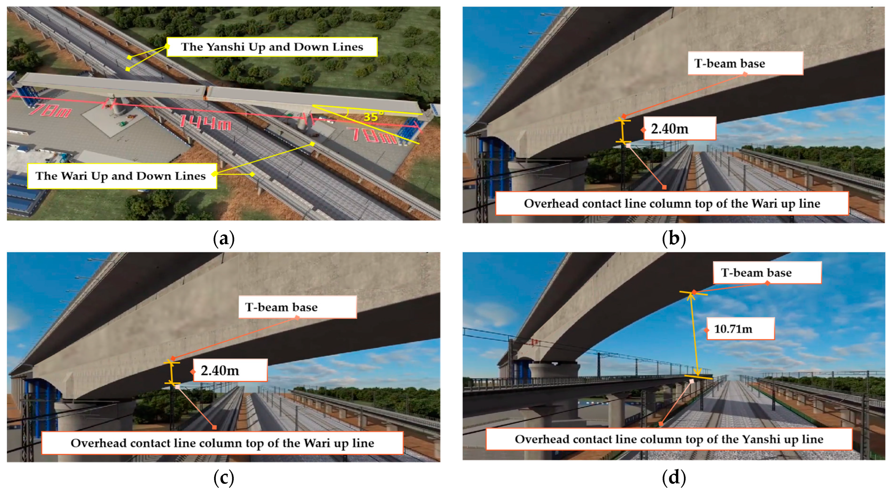
The Xiaojiazhuang Bridge stands as a pivotal project within the Lunan High-Speed Railway in China, including the largest span, the closest proximity to operational railway lines, the highest number of railway crossings and the most extended T-beam swivel construction within Shandong Province. This bridge spans four distinct railway lines, namely the Yanshi Up and Down Lines and the Wari Up and Down Lines, intersecting them at a precise angle of 35 degrees. The dual-track T-beam continuous beam configuration, measuring (78 + 144 + 78) meters in length, predicates the bridge’s structural design. The swivel bridge structure commands a considerable mass of 25,000 tons. To minimize operational disruptions from the SBC over existing railway lines and to maintain safety, the ball-joint method was employed for swivel construction at the 18th and 19th central piers. The asymmetrical cantilevering process was initially undertaken along the existing railway lines, forming two distinct T-structures. Swivel construction was executed upon reaching the designated position. A schematic diagram of the relationship between Xiaojiazhuang Bridge and the existing lines is shown in Figure 2.
The construction of the Xiaojiazhuang Bridge demanded strict planning and execution due to its tight schedule and significant responsibilities. The massive scale of the individual segments required unprecedented precision during the construction phase, a factor further compounded by the substantial weight of the individual continuous beam segments. The complexity of installing the rotational system required high construction accuracy. An essential safety goal was to minimize construction risks on the operational line, particularly during the installation and removal of continuous girder templates. Optimizing methods and simplifying complex procedures were crucial to reducing the impact on the operational line and achieving a zero-accident goal.
To facilitate the successful realization of these safety management goals, implementing the Fuzzy-ISM-MICMAC method is instrumental in facilitating the risk control of continuous girder rotation construction, providing a robust theoretical foundation for achieving the safety control objectives.

4.2. Determination of the Risk Factors

The project team used two standard risk assessment methods to identify critical risks, minimize construction risks on the operational line and aim for zero accidents. Initially, the primary controlling factor method identified three significant risks for the bridge construction: the location over an active mainline railway, a turning span exceeding 100 m and novel structures and processes [13,41]. Further analysis with the index system method [13,41] highlighted three critical aspects: proximity to high-voltage lines, the inability to close the railway during construction and complex, frequent construction processes.
By combining the project team’s analysis, Table 1’s inventory and Xiaojiazhuang Bridge’s specifics, this study identified 39 risk factors for SBC spanning ERLs. Subsequently, the Work Breakdown Structure–Risk Breakdown Structure (WBS–RBS) methodology [7] was employed to cluster and analyze these 39 risk factors systematically, expounded in Table 3.
Modifications and simplifications were undertaken through expert interviews to refine the rationality and semantics of the risk factor inventory further (Table 3). This on-site face-to-face expert interview was conducted in Jinan, China, from 10 July to 11 July 2022. This study incorporated insights from five experts, whose profiles are detailed in Table 4. The group included three individuals, who work as technical directors and safety supervisors with significant experience in SBC spanning ERLs, and two professors with expertise in bridge construction risk management research.
In the initial round of interviews, expert insights were utilized to eliminate relatively minor influences, incorporate previously unrecognized factors and consolidate risk factors with closely related connotations. This iterative process resulted in a streamlined set of 32 risk factors. Subsequently, in the second round of semi-structured interviews, conceptual descriptions were provided for these 32 risk factors. Following expert input, these descriptions were systematically clustered and refined. The revised risk factor list, along with their definitions, was once again subjected to expert scrutiny. After accommodating the expert-driven revisions, the ultimate risk factors specific to SBC spanning ERLs were distilled into 28, as detailed in Table 5. These present a theoretical framework for understanding the risks and safety issues associated with bridge rotational construction across railway lines.
Two categories of risk factors have not yet been explicitly accounted for. (1) For the railway “skylight” time, the determination of construction window opening times involves communication and coordination between the project owner, construction entity and railway operator [33,36]. These timings are set prior to the development of the construction plan and typically cannot be adjusted to align with construction needs [42]. Consequently, the construction plan is inherently constrained by these predetermined construction window opening times, making this aspect a constraining factor rather than a risk factor that can be controlled by human intervention. (2) Adverse weather conditions have been addressed in various risk assessments; however, the specific focus of this study, which involves “continuous beam rotation construction over existing railway lines”, introduces unique complexities. Unlike conventional bridge construction, this endeavor entails significantly greater construction complexity and difficulty, and it explicitly forbids construction activities during adverse weather conditions [39]. Adverse weather conditions are characterized by their sudden and unpredictable nature [42]. Due to the prohibitive costs and technical challenges associated with human intervention, adverse weather represents a construction context where avoidance is the only practical strategy rather than a risk factor that can be managed through human control.

4.3. Computation of the Reachability Matrix through Semi-Structured Expert Interviews

ISM analysis relies on expert insights, utilizing their knowledge and experience to create matrices that define the relationships and overall structure of complex element sets [52,53,54]. Therefore, acquiring in-depth and intricate responses from high-quality interviewees is essential for constructing a hierarchical model. Nonetheless, semi-structured interviews are commonly favored as the method for data collection [55]. This approach enables the researcher and the interviewee to engage thoroughly and clearly in the interview topics, exploring them in greater detail without confusion or ambiguity [50,54].
We undertook a comprehensive approach to meticulously analyze the interrelationships between risk factors impacting the safety of ongoing continuous beam rotation construction on existing lines, as detailed in Table 3. Initially, we conducted semi-structured interviews with five experts to determine the nature of the contextual relationship between each pair of risks and whether one risk “leads to” or “influences” the other risk for each pair. To ensure the scoring process remained free from potential external disruptions, we conducted these interviews through two rounds of email communication from 1 September to 30 September 2022. Their profiles are detailed in Table 4. Following the guidelines outlined in Table 5, these experts were assigned to conduct a detailed fuzzy scoring of the interrelationships among the identified risk factors.
The consequent responses were aggregated, with the mean value of the data retrieved being utilized as the constituents of the fuzzy adjacency matrix (F). The correlation strength matrix (B) was formulated based on matrix F under the guidelines of Equation (3). This was followed by a rigorous comparative analysis of the individual elements to ascertain the optimal threshold value (λ).
It is imperative to note that a diminished λ value potentially culminates in fewer stratifications of factors, thereby obscuring the intricate, underlying relationships among them. Conversely, an escalated λ value might engender an augmentation in level divisions, thereby impeding the comprehensive understanding of the interrelationships among the factors. Given these considerations, this study was oriented toward ensuring the pinnacle of system performance. Consequently, based on the fuzzy evaluation criteria and the insightful perspectives rendered by the experts, a λ value of 0.5 was discerningly chosen. Following this, Equation (3) was utilized to manipulate correlation matrix B, thus facilitating the derivation of the adjacency matrix (A). Further, employing the functionalities of the software named MATLAB 2019b, the reachability matrix (M) was computed in strict adherence to Equations (4) and (5).
The Adjacency Matrix A
F1F2F3F4F5F6F7F8F9F10F11F12F13F14F15F16F17F18F19F20F21F22F23F24F25F26F27F28
F10000011000000000000000000000
F20000000001000011110000000000
F30000000000001000000000000000
F40000000001010000000000000000
F50000000000000000001000000000
F60000000000000000000000100000
F70000000001000000000000000000
F80000000000000000000000100000
F90000000000000000000000001000
F100000000000000000000000000011
F110000000000000000000000000001
F120000000000000000000000011100
F130000000000000000000000100000
F140000000000000000000000100000
F150000000000000000000000010101
F160000000000000000000000111001
F170000000000000000000000011001
F180000000000000000000000010000
F190000000000000000000001000000
F200000000000000000000000001100
F210000000000000000000001000000
F220000000000000000000000000010
F230000000000000000000000000001
F240000000000000000000000000100
F250000000000000000000000000000
F260000000000000000000000000000
F270000000000000000000000000000
F280000000000000000000000000000
The Reachability Matrix M
F1F2F3F4F5F6F7F8F9F10F11F12F13F14F15F16F17F18F19F20F21F22F23F24F25F26F27F28
F11000011001000000000000100011
F20100000001000011110000111111
F30010001001001000000000100001
F40001000001010000000000011111
F50000101001000000001001000010
F60000010000000000000000100001
F70000001001000000000000000011
F80000000100000000000000100001
F90000000010000000000000001000
F100000000001000000000000000011
F110000000000100000000000000001
F120000000000010000000000011100
F130000000000001000000000100001
F140000000000000100000000100001
F150000000000000010000000010101
F160000000000000001000000111101
F170000000000000000100000011101
F180000000000000000010000010100
F190000000000000000001001000010
F200000000000000000000100001100
F210000000000000000000011000010
F220000000000000000000001000010
F230000000000000000000000100001
F240000000000000000000000010100
F250000000000000000000000001000
F260000000000000000000000000100
F270000000000000000000000000010
F280000000000000000000000000001

4.4. Establishing the Hierarchical Structure of Risk Factors Based on ISM

We conducted hierarchical decomposition based on the reachability matrix M. First, we calculated the reachability set and the antecedent set of influencing factors according to Equations (6) and (7), wherein the intersection of the reachability set and the antecedent set constitutes the common set R P i , as demonstrated in Table 6.
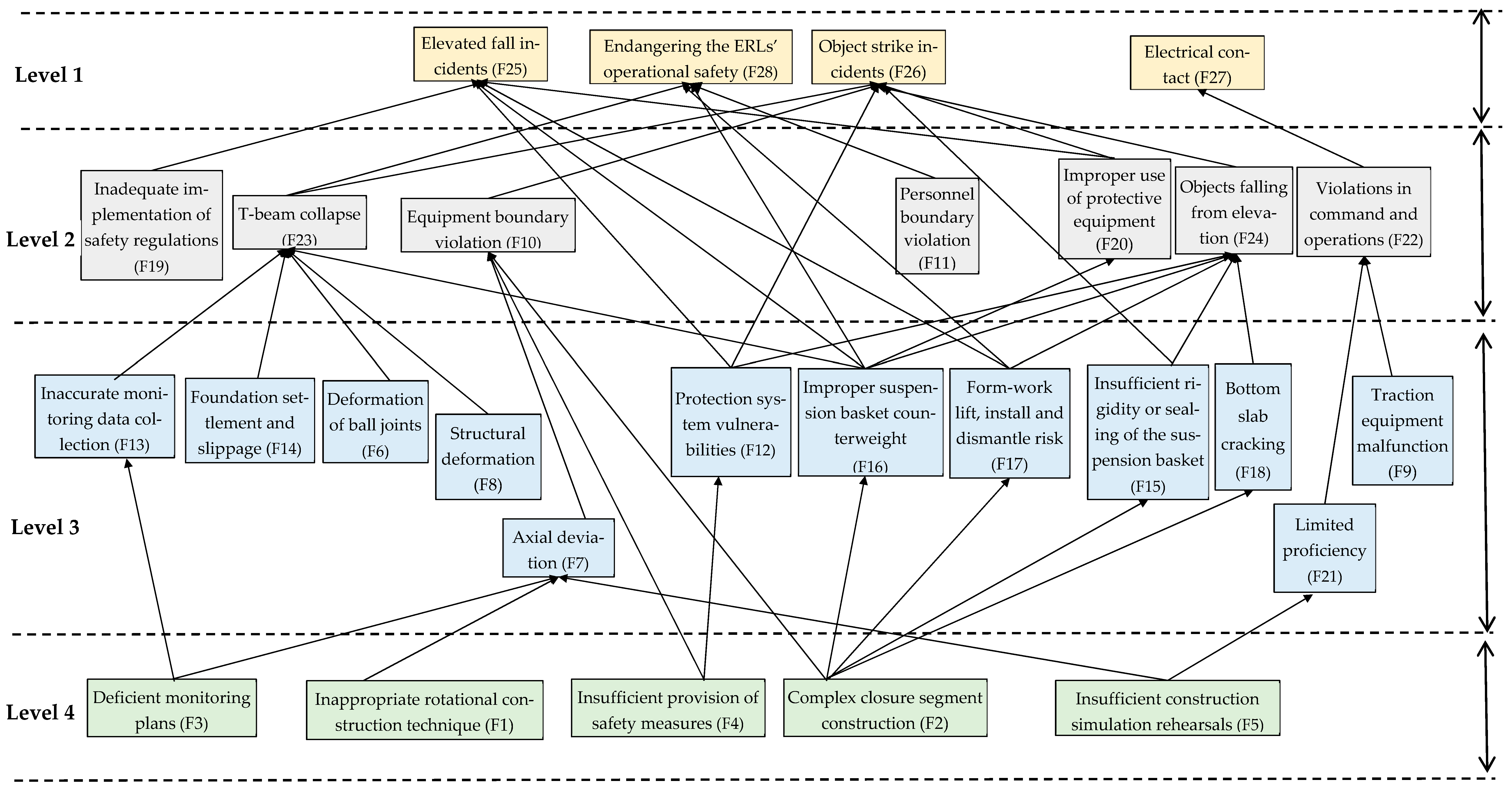
Following this, utilizing the results obtained from the preliminary computations, the hierarchical relationships were ascertained by employing Equation (8) to scrutinize the intersections, thus facilitating the establishment of a rigorously delineated hierarchical structure. L1 = [16 F28]; L2 = [16 F20, F22, F23, F24]; L3 = [16 F12, F13, F14, F15, F16, F17, F18, F19, F21]; L4 = [16 F4, F5]. Utilizing the results derived from the stratification process, a schematic representation delineating the hierarchical interrelationships of risk factors impacting safety during the rotational construction of continuous girders across existing lines was constructed. This schematic systematically depicts all direct associations based on the adjacency matrix A, resulting in a nuanced multi-level progressive structure, as exemplified in Figure 3.
As per the interpretive structural model, the delineation of risk factors is organized into three prominent hierarchical levels. These are classified as L1, serving as the superficial layer depicting initial, observable phenomena; L2 and L3, which function as the intermediary layers that encapsulate transitional and evolving factors; and finally, L4 and L5, which represent the root layer, housing the fundamental causes and underpinning forces driving the observed risks. This systematic categorization aids in a more structured and deep-rooted analysis of the potential risks.
L1 epitomizes the superficial layer of risk factors, prominently positioned at the zenith of the ISM framework. This layer encapsulates variables such as F25, F26, F27 and F28, highlighting the potential threats to the existing line’s traffic safety. These variables directly influence the safety dynamics of continuous girder rotation construction spanning existing lines, thereby delineating the quintessential focal points for safety management and control initiatives.
Addressing these pronounced risk factors necessitates a multifaceted strategy, intricately weaving interventions to mitigate foundational and intermediary risk elements. For instance, averting the perils associated with personnel falling from significant heights necessitates the enhancement of protective frameworks, thereby diminishing the inherent vulnerabilities present within the F12 protective system structure. Concurrently, ensuring a balanced configuration within lifting baskets stands crucial in neutralizing the perils represented by F16, relating to the counterweight’s rotational dynamics at the extremities of the baskets. Moreover, amplifying safety protocols during pivotal stages such as template hoisting, installation and dismantling mitigates the associated risk dimensions. The adept utilization of safety harnesses emerges as a vital strategy in circumventing the risks designated by F20, predominantly concerning the misuse of safety protective equipment. Furthermore, rectifying prevalent malfunctions within the traction equipment stands imperative in addressing the complications of F9. On a foundational stratum, it demands the bolstering of safety measures and managerial oversight onsite, orchestrating efforts toward negating potential risks denoted by F2, thus fostering a work environment grounded in stringent safety paradigms.
L2 and L3 constitute the intermediate echelons of risk factors, serving a critical function in mediating the foundational and superficial layers within the confines of ISM. These factors are invariably restrained by the intrinsic risk elements residing at the base stratum and concurrently exert a discernible influence on the manifest risk factors at the superficial layer. This segment embodies a total of 19 risk variables, namely F6, F7, F8, F12, F13, F14, F15, F16, F17, F18, F19, F21, F9, F10, F1, F20, F22, F23 and F24. These entities represent indirect influential variables, demonstrating a cascading and stratified interrelationship.
Within this intricate matrix, two salient conduits of risk transmission are discernible. First, those elements find themselves subordinate to the foundational risk constituents entrenched in the basal layer. Although these elements do not have a direct nexus with safety incidents during construction, they facilitate the percolation of influences to the superficial layer through a sophisticated interplay with foundational components. For example, variable F7, indicative of axial deviation, is confined by the repercussions of F1, a misjudged selection of rotational construction techniques; F3, inadequate surveillance strategies; and F5, alack of comprehensive pre-construction simulation drills. This variable notably impacts F10, denoting equipment and facility encroachment, thereby indirectly precipitating a ripple effect on the superficial risk entity F28, which encapsulates threats to existing line vehicular safety.
Second, we recognize a subset of relatively autonomous risk factors, encompassing variables such as F6, which signifies deficient quality in spherical hinge construction; F8, representing structural component degradation; F14, highlighting severe foundational subsidence and slippage; and F21, pinpointing a deficiency in skill levels amongst construction personnel. These variables remain primarily unencumbered by the foundational layer’s risk determinants, directly influencing other intermediate-layer risk entities. This influence eventually proliferates, indirectly impacting the risk factors situated at the superficial layer. The intricate nexus amongst these variables posits a complex scenario, epitomizing the focal points and intricate challenges intrinsic to mitigating and managing construction risks.
L4 epitomizes the nucleus of risk factors in continuous girder rotation construction over existing lines. It serves as a reservoir of fundamental issues that profoundly affect the safety protocols associated with such construction projects. This tier encompasses critical factors, including F1, F2, F3, F4 and F5. These elements hold substantial sway over the safety aspects of continuous girder rotation construction, pointing to crucial issues that necessitate urgent and meticulous attention in managing and mitigating risks in these engineering ventures.
At the apex of foundational risk analysis, these factors clearly outline the significant impact that initial steps such as the careful selection of technological applications, strategic conceptual design development, preparatory construction rehearsals and the establishment of robust safety infrastructure can have on the emergence of risk elements during critical phases of the rotation construction process. By adeptly addressing these entrenched risk factors, one can significantly curtail the propensity for risk occurrences at the intermediate and superficial layers, potentially obviating them in entirety.
However, it is essential to recognize that neglecting to adequately emphasize or thoroughly evaluate these deep-rooted risk factors could significantly weaken the effectiveness of risk management strategies. This scenario accentuates the absolute necessity for an incisive and methodical approach to risk mitigation right from the inception of these projects. Therefore, this standpoint necessitates a heightened level of analytical engagement, fostering a paradigm where the comprehensive containment of intrinsic risks is achieved at their genesis, thereby engendering an operational environment characterized by augmented safety and control.

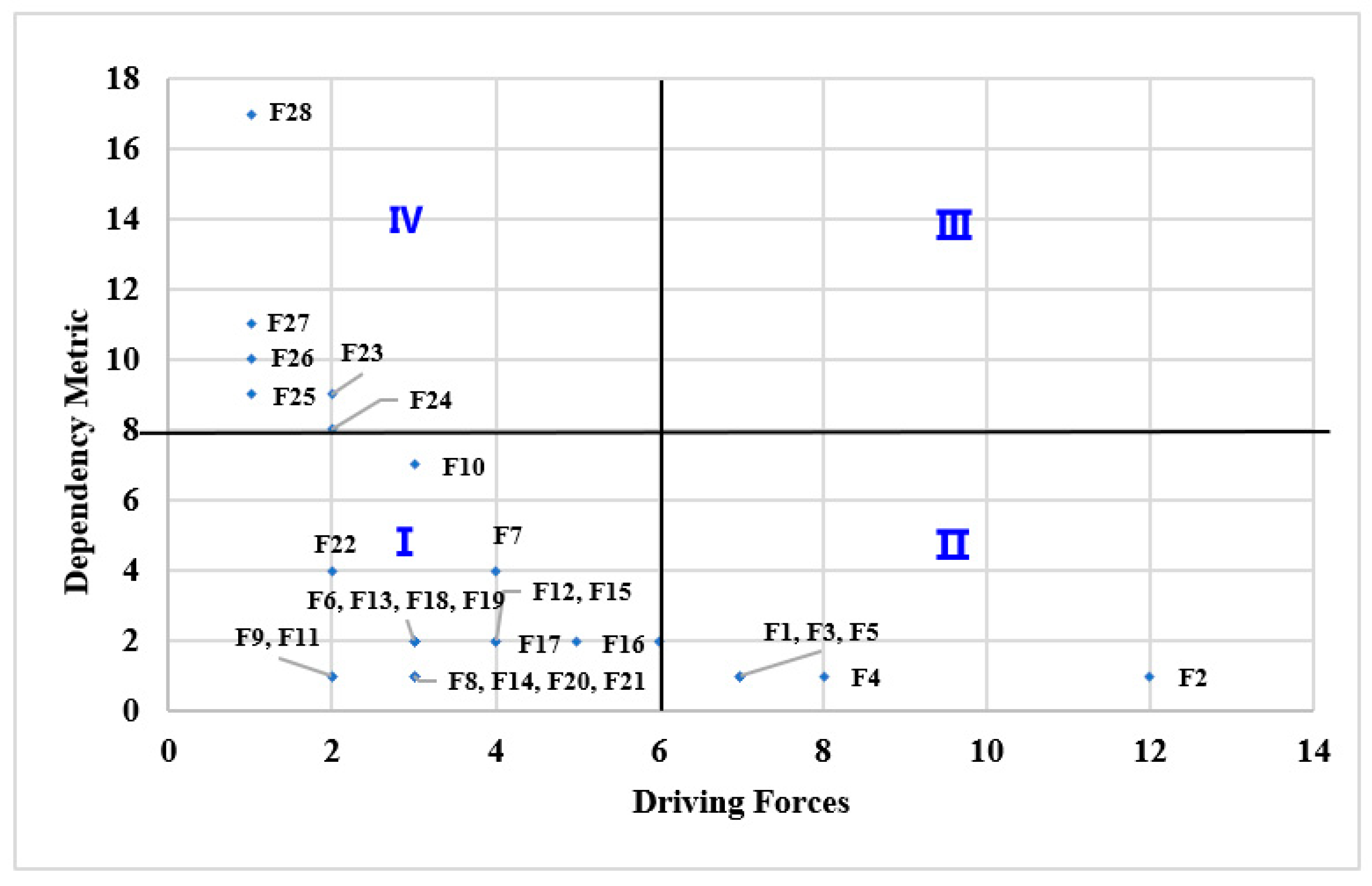
4.5. Analysis with MICMAC

Upon acquiring the hierarchical structure of risk factors affecting the safety of continuous girder rotation construction over existing lines, and in conjunction with the categorization determined through MICMAC method analysis, a profound segmentation of the positions and roles of the risk factors was conducted. This delineation ascertained the corresponding dependencies R j and driving forces D i , thereby formulating more targeted countermeasures for different risk factors.
Upon the foundation of the established reachability matrix M, a rigorous MICMAC analysis was undertaken. Dependency is characterized as the number of elements designated as ‘1’ within the respective columns correlating to each factor in the matrix M, whereas driving power signifies the number of elements denoted as ‘1’ within the respective rows corresponding to each factor therein.
Using the analytical frameworks outlined in Equation (9) through (10), a detailed calculation of the driving forces and dependencies of the influencing factors was carried out. Here, λ was instituted as a metric to encapsulate the relative scale of relationships between driving power and dependency, mathematically represented as λ = driving power/dependency. The computations culminated in results, which are comprehensively delineated in Table 7.
Following the findings delineated in Table 7, a quadrant analysis was conducted, utilizing the median values of dependency and driving forces as bifurcation parameters to segment the coordinate axis into four distinct sectors: I (Autonomous Cluster), II (Independent Cluster), III (Linkage Cluster) and IV (Dependency Cluster). As manifested in Figure 4, this analytical framework explicates the intricate affiliations and categorical interdependencies subsisting among the various influential factors, providing a robust platform for nuanced analysis and stratification in risk management processes.
The ensuing analysis is presented herein, incorporating the findings delineated in Figure 3 and Figure 4.
(1) The risk elements within the dependency cluster demonstrate a high degree of reliance but possess diminished propulsive forces, generally necessitating resolutions from the autonomous and independent clusters of risk factors for effective mitigation. This group encompasses factors such as F23, F24, F25, F26, F27 and F28, predominantly localized within the L1 and L2 strata of the hierarchical structural diagram, thereby being principally subjected to influences from subordinate components. For instance, T-beam overturning risk aversion (F23) critically hinges upon the efficacious management of a suite of other risk constituents, including F8, which pertains to component damage; F6, addressing the issues of subpar spherical hinge construction quality; F13, denoting inaccuracies in monitoring during the pivotal rotation phase; F14, highlighting serious foundational settlement; and F16, focusing on the perils associated with beam-end basket counterweight rotation risks. The in-depth management of these ancillary risk variables serves as a cornerstone in negating the potential repercussions associated with F23, thereby underscoring the vital interdependency and nuanced complexity embodied within this risk matrix.
(2) Within the ambit of the autonomous cluster, risk factors demonstrate a notable parity in their levels of dependency and driving force, embodying a complex and balanced dynamism in the context of risk management. This category encapsulates factors such as F6, F7, F8, F12, F13, F14, F15, F16, F17, F18, F19, F9, F10, F11, F20, F22 and F24. These constituents are prominently positioned within the L2 and L3 echelons of the multilevel hierarchical structure diagram, indicating a sophisticated role where they not only assimilate influences from the underlying strata but also impart considerable influences onto the higher tiers. Consequently, these elements function as critical nodal points in the risk network, facilitating a cascade of effects that both stem from and influence a wide array of other risk factors, thereby assuming a central role in the transmission and modulation of risk attributes across different layers of the analytical framework. This elucidation underscores their integral function in mediating and transmitting influences, thereby serving as essential conduits in the intricate web of risk interdependencies and interactions.
(3) Linkage Cluster Risk Factors. This category of risk factors is absent in the current analysis, indicating that the selected risk factors are relatively stable without demonstrating prominent characteristics of linkage or chain reactions.
(4) Risk Factors About the Independent Cluster. The risk factors classified within this cluster are characterized by a pronounced predominance of driving forces as opposed to dependency levels, delineating a high degree of autonomy in influencing the project’s outcome. This category encompasses elements F1, F2, F3, F4, F5 and F21, strategically positioned at the L4 layer within the hierarchical structure delineated in the multi-level progressive structural diagram. These fundamental factors exert a pervasive influence over all superior tiers, facilitating a nuanced analysis of root causality should discrepancies manifest within the upper echelons, thereby enabling targeted adjustments and interventions.
Per the project-specific constraints encapsulated by environmental, organizational and procedural parameters, selecting rotational construction methodologies and conjunction segment construction techniques becomes incumbent. This strategy mitigates many construction safety risks emanating from procedural complexities. Furthermore, deploying sufficient onsite safety provisions and formulating rigorous monitoring schemas substantiate establishing a fortified safety infrastructure. Incorporating cutting-edge technologies for the in-depth simulation and rehearsal of construction sequences buttresses existing preventative measures, engendering a robust protective framework. A pivotal role is carved in precluding the emergence of risks intrinsic to both autonomous and dependent clusters through comprehensive and precise safety technical briefings. These elements unequivocally constitute the linchpin in orchestrating safety risk management and control during continuous girder rotation construction across existing lines.
This research focuses on the critical risk factors identified at the root layer and within the independent cluster to effectively manage and control the risks affecting the safety of continuous girder rotational construction over existing lines. The effective prevention of safety accidents during the rotation construction of continuous beams across existing lines can be initiated from fundamental layers and critical risk factors of independent clusters, adopting proactive preventative measures to concurrently regulate upper-level factors and mitigate the impact of lower-level elements.
This study is limited to certain interdependencies among the risks, and some safety measures could be implemented to reduce hazards. Various safety protection measures are adopted both technically and managerially, which collectively help regulate the factors in the upper layers and reduce the influence of the factors in the lower layers. These measures include the following:
  • Making a judicious selection of rotational system structural technology.
  • Enhancing safety protective measures during basket construction.
  • Optimizing the construction technique during the mid-span closure segment.
  • Implementing an automatic real-time monitoring system for precise surveillance during the rotational process.
  • Fully utilizing BIM technology for construction simulation, actively predicting and guiding the prevention and control of construction risks.
  • Ensuring that all workers involved in these activities receive appropriate safety training.

5. Discussion

This study uncovers the relationships and interdependencies among risk factors in SBC spanning ERLs. We believe that addressing key risk factors at the root level and independent clusters with various technical and managerial safety measures can regulate upper-level factors and mitigate the impact of lower-level ones. We applied these findings to the Xiaojiazhuang Grand Bridge’s double T-structure swivel construction to test their practicality and efficiency. The subsequent discussion is vital for evaluating our recommendations’ practical application and provides more specific solutions for safety management in similar bridge construction projects. Additionally, these technical and managerial safety measures have been recognized by peer experts and incorporated into two construction standards [13,41].

5.1. Research on Rotation System Structural Technology

The ten-thousand-ton continuous beam rotation system is characterized by high construction difficulty, stringent quality standards, advanced technical levels and complex structures [42]. This case opts for the spherical hinge rotation construction technique, where the rotation system primarily relies on spherical hinge support, employing the strut to control the rotation stability and utilizing the traction system to apply rotational torque. During construction, stringent controls are placed on the spherical hinge plane’s relative height differences and the spherical hinge center’s longitudinal and lateral errors [34]. When the upper spherical hinge is installed, the rotational and centroidal axes must coincide, with errors not exceeding 1 mm. It addresses root-level and independent cluster risk factors, such as unreasonable choices in rotation construction techniques. Subsequently, it averts direct and intermediate-level risks and indirect influences on dependent clusters and other risk factors.

5.2. Safety Protective Measures for Basket Construction

Beam closure section construction typically uses the protective shed + basket method, erecting steel protective sheds above and below the baskets to cover and protect the lines [26]. Although this approach is technically mature, providing good protection for existing lines and facilitating construction operations, it has requirements regarding the distance between the beam bottom and existing lines. The protective shed can only prevent the fall of small objects and cannot prevent large, heavy and sharp objects from falling onto the lines [39]. Moreover, the protective shed poses a significant safety risk during installation and removal, with high costs and low efficacy.
For the rotation of continuous beam construction near the operational lines on Xiaojiazhuang Bridge, custom-designed special enclosures were employed, optimizing the force structure of the basket to control deformation and enhance safety margins effectively. The basket operation platform and edge protection adopted integral assembly-type standardized processing, effectively avoiding complex situations arising from F2 closure section construction techniques, directly reducing the occurrence of risk factors such as F10, F15, F16, F17 and F18 and indirectly minimizing the occurrence of risk factors such as F25, F26 and F28.

5.3. Application of an Automatic Real-Time Monitoring System during the Rotation Process

In adverse weather and working conditions, onsite manual measurement poses safety risks [39]. It involves large computation volumes and is prone to observational errors, and managers cannot comprehensively understand the construction site conditions remotely [42]. Manual measurements cannot satisfy the requirements for continuous monitoring, making risk factors like F7 and F13 likely to occur. A three-dimensional virtual simulation monitoring system can be used for automatic monitoring [56]. Automatic monitoring is not affected by adverse weather and working conditions, safeguarding personal safety. Managers can comprehensively grasp the construction site’s conditions in real time and remotely, providing timely guidance if issues arise. It allows for continuous round-the-clock measurements, meeting continuous monitoring needs, significantly reducing measurement costs, reducing labor usage and ensuring rotation precision [57]. This method directly reduces the probability of risk factors such as F13 from occurring, indirectly influencing the occurrence of risk factors like F23 and F28.

5.4. Optimization of the Mid-Span Closure Section Technique

Traditional techniques involve using protective sheds and baskets for mid-span closure section beam construction [33]. Removing closure section basket molds requires retracting the basket or lifting the mold outside the lines, presenting a significant safety risk during operation [7,39]. Traditional techniques have high safety risks, high costs and low efficiency [42]. They can easily trigger risk factors such as F10, F15, F16, F17 and F18. Adopting new techniques to replace traditional ones directly avoids risk occurrences, like using steel boxes to replace basket construction techniques, saving costs, shortening the construction period and reducing construction risks.
Given the high safety risks, short construction time and significant impact on existing operational lines during mid-span closure section construction following continuous beam rotation, this research proposes adopting a technique where steel boxes are embedded in the mid-span in advance to replace continuous beam baskets. Steel boxes can be used as molds and protection, allowing for minimal impact on the line space during operation. In addition, it has good enclosure properties, and there is no need for removal processes after the closure section construction is complete. This method is straightforward, eliminating safety risks to existing lines and allowing for operations within the steel box without unnecessary points, with low costs and short construction periods. It resolves the complex problems of closure section construction techniques at the root level, directly reducing the probability of risk factors such as F10, F15, F16, F17 and F18 from occurring and indirectly minimizing the occurrence of risk factors like F24, F25, F26 and F28.

5.5. Application of BIM Technology in Rotation Construction

Specifically addressing continuous beam rotation where the structure has large dimensions, intricate internal constructions, varying rotation conditions and tight schedules with great difficulty, precision requirements and irreversible multiple construction tasks, BIM technology is employed to simulate the positions of internal rebars and corrugated pipes within the continuous beam, as well as the relational positions during beam rotation [58,59]. This solves the challenges of precise pre-stressed pipe positioning and large-volume continuous beam concrete pinpoint vibration technology, realizing perfect continuous beam rotation with precise positioning.
Using BIM technology to simulate the dynamics of the continuous beam structure and construction conditions maximizes pre-warning before construction when operations are conducted at critical points along operational lines, ensuring construction safety and efficiency [60]. Through BIM + drones + three-dimensional scanning technology, three-dimensional arrangements of the construction site have been completed [61], verifying the spatial relationships of construction operations and simulating collision tests, closure construction and project quantity verification [62]. It provides proactive predictions and guidance for the standard construction of a bridge without affecting railway traffic [63].

6. Conclusions, Limitations and Applications

6.1. Conclusions

Adopting rotational construction technology for bridge construction across existing railway lines has significant advantages when the construction time frame and site are constrained. To identify critical points for risk control, this study employs a literature review, a case study, expert interviews and the Fuzzy-ISM-MICMAC method to investigate the risk factors affecting SBC spanning ERLs.
This study’s findings can be summarized as follows:
  • Identification and establishment of risk factors affecting SBC spanning ERLs, encompassing 6 categories and 28 individual factors.
  • Utilizing Fuzzy-ISM and conducting an analysis with MATLAB software, a four-layer ISM hierarchical structure chart was constructed. Herein, L1 serves as the superficial layer, L2 and L3 function as intermediate layers, and L5 and L4 constitute the root layers. Coupled with MICMAC analysis, the risk factors were classified into four clusters according to their dependence and driving force. We elucidated the hierarchical relationships degrees, transmission paths and the mutual driving and dependency relationships among the 28 risk factors, clarifying the mechanisms of risk factor influences.
  • Risk factors in the independent cluster, such as F1, F2, F3, F4, F5 and F21, are located at the root layer, L4, of the multi-level hierarchical structure chart and can influence all factors in the upper layers. Adjusting and intervening in these factors is vital in averting risks in the autonomous and dependent clusters.
  • Preliminary tasks like selecting construction techniques, scheme design, construction rehearsal and equipping safety facilities exert a foundational restrictive influence on the emergence of risk factors during the rotational construction stage, representing fundamental issues that need urgent resolution in risk control.

6.2. Limitations

This study analyzes the mechanisms influencing the risk factors, hierarchical relationships and transmission pathway relationships affecting SBC spanning ERLs. It puts forth targeted risk control suggestions through an empirical case application. Although it provides several valuable conclusions and applications, two limitations should be noted.
First, any rotational construction of bridges over existing lines has unique characteristics. The determination of current risk factors is aligned with the features of the Xiaojiazhuang Bridge case study. If applied to other swivel bridges, it would be necessary to modify the set of risk factors according to the specific characteristics of those swivel bridges. Second, future studies could intensively examine how risk factors are intrinsically related, employing quantitative approaches like Bayesian network modeling.

6.3. Future Research and Practical Applications

  • Risk management studies for diverse swivel bridges.
Research should concentrate on detailed risk assessments for various swivel bridge designs, incorporating comparative analyses to develop specific risk management strategies.
  • Integrating findings into education and training.
Embedding these research insights into the educational curriculum and training modules for engineers and construction workers is imperative, emphasizing updated methodologies and practical applications.
  • Case studies and empirical validation.
Implementing and scrutinizing these strategies in real-world swivel bridge projects is crucial for empirical validation, providing substantive contributions to industry standards and best practices.

Author Contributions

Conceptualization, C.P.; Data curation, C.P.; Formal analysis, C.P. and H.C.; Funding acquisition, H.C.; Investigation, J.W.; Methodology, C.P. and R.T.; Project administration, H.C.; Resources, J.W.; Software, R.T.; Writing—original draft preparation, C.P.; Writing—review and editing, C.P. All authors have read and agreed to the published version of the manuscript.

Funding

This research was funded by the Shandong Transportation Science and Technology Plan (grant number 2021B98) and the Scientific and Technological Progress and Innovation Plan from the Hunan Transportation Department (grant number 202234).

Data Availability Statement

The data presented in this study are available on request from the corresponding author. The data are not publicly available due to personal privacy is involved in the semi-structured expert interviews.

Acknowledgments

The authors are grateful for the comments and recommendations from the editors and anonymous reviewers.

Conflicts of Interest

Author Jiquan Wang was employed by the company Shandong Railway Investment Holding Group Co., Ltd. The remaining authors declare that the research was conducted in the absence of any commercial or financial relationships that could be construed as a potential conflict of interest.

Abbreviations

SBCSwivel Bridge Construction
ERLsExisting Railway Lines
ISMInterpretive Structural Modeling
FISMFuzzy Interpretive Structural Modeling
MICMACMatrice d’Impacts Croisés Multiplication Appliquée à un Classement (in French)
Cross-Impact Matrix Multiplication Applied to Classification (in English)
WBS–RBSWork Breakdown Structure–Risk Breakdown Structure
AHPAnalytic Hierarchy Process
CNKIChina National Knowledge Infrastructure

References

  1. DG/TJ 08-2220-2016; Technical Specification for Horizontal Swivel Construction Method of Bridge: Construction Standards of Shanghai City in China. SMD Institute: Shanghai, China, 2016. (In Chinese)
  2. Wang, D.; Liu, Z.; Gao, J.; Li, C.; Guo, T. Swivel Construction of a Cable-Stayed Bridge for Minimal Disturbance to Adjacent Railways. Struct. Eng. Int. 2023, 33, 498–505. [Google Scholar] [CrossRef]
  3. Lei, L. Research on Swivel Construction Technology of Continuous Box Girder Bridge across Existing Railway Lines; Shandong University: Jinan, China, 2017. (In Chinese) [Google Scholar]
  4. Gang, H. Research on the Swivel Construction Technology of the Expressway across the Existing Railway Line; Chang’an University: Xi’an, China, 2018. (In Chinese) [Google Scholar]
  5. Su, M.; Wang, J.; Peng, H.; Cai, C.S.; Dai, G.L. State-of-the-art review of the development and application of bridge rotation construction methods in China. Sci. China Technol. Sci. 2021, 64, 1137–1152. (In Chinese) [Google Scholar] [CrossRef]
  6. Liu, M. Construction Technology and the Application of Rotation Construction Method on Bridges across Existing Railway Lines; Science Press: Beijing, China, 2016. (In Chinese) [Google Scholar]
  7. Chen, H.; Chen, H.; Hu, X. On safety-influencing factors and accident-causing mechanisms of swivel construction of bridges across existing railway lines. J. Railw. Sci. Eng. 2020, 17, 1595–1602. [Google Scholar]
  8. Almomani, H.A.; Almutairi, O.N. Life-Cycle Maintenance Management Strategies for Bridges in Kuwait. J. Environ. Treat. Tech. 2020, 8, 1556–1562. [Google Scholar]
  9. Keyin, L. Research on Design and Construction of Double-frame Short-range Synchronous Swivel Rigid Frame Bridge. China Foreign Highw. 2014, 34, 157–160. (In Chinese) [Google Scholar]
  10. Che, X.; Zhang, X. Overturning resistance of large tonnage T-shaped rigid frame bridge during turning process. China J. Highw. Transp. 2014, 27, 66–72. (In Chinese) [Google Scholar]
  11. Xiangxi, Z. Research on Beam Stress and Deformation Monitoring during Construction of Synchronous Swing Bridge across Railway. Railw. Constr. Technol. 2016, 2, 23–26. [Google Scholar]
  12. Rongfeng, G. Construction Technology of 2 × 100 m T Swing Bridge on Upper-Span Highspeed Railway. Constr. Technol. 2017, 46, 963–966. (In Chinese) [Google Scholar]
  13. DB 13/T-5576-2022; Technical Specification for Horizontal Swivel Construction Method of Highway Bridge Overcrossing Railway: Hebei Provincial Local Standards. Hebei Provincial Market Supervision and Administration Bureau: Hebei, China, 2022. (In Chinese)
  14. Ojha, A.; Seagers, J.; Shayesteh, S.; Habibnezhad, M.; Jebelli, H. Construction safety training methods and their evaluation approaches: A systematic literature review. In Proceedings of the 8th International Conference on Construction Engineering and Project Management, Hong Kong, China, 7–8 December 2020. [Google Scholar]
  15. Morteza, A.; Ilbeigi, M.; Schwed, J. A blockchain information management framework for construction safety. Comput. Civ. Eng. 2021, 2021, 342–349. [Google Scholar]
  16. Rashidi Nasab, A.; Malekitabar, H.; Elzarka, H.; Nekouvaght Tak, A.; Ghorab, K. Managing Safety Risks from Overlapping Construction Activities: A BIM Approach. Buildings 2023, 13, 2647. [Google Scholar] [CrossRef]
  17. Shamshiri, A.; Ryu, K.R.; Park, J.Y.; Choi, K. Project Phase–Based Contingency Adjustment Framework for Infrastructure Renewal Projects. J. Constr. Eng. Manag. 2023, 149, 04022176. [Google Scholar] [CrossRef]
  18. Tavakolan, M.; Etemadinia, H. Fuzzy Weighted Interpretive Structural Modeling: Improved Method for Identification of Risk Interactions in Construction Projects. J. Constr. Eng. Manag. 2017, 143, 04017084. [Google Scholar] [CrossRef]
  19. Jiang, X.Y.; Yan, B.Q.; Yu, J.Y.; Liu, Y. Identification of Hierarchical Relationship of PPP Critical Risks Using Integrated ISM-fuzzy and MICMAC Approach. J. Civ. Eng. Manag. 2018, 35, 71–77. [Google Scholar]
  20. Taitian, M.; Jiawei, M. Research on Influencing Factors and Correlation Paths of Health Information Avoidance Behavior Based on Fuzzy ISM-MICMAC. Inf. Doc. Serv. 2023, 44, 84–92. [Google Scholar]
  21. Sampaio, A.Z.; Martins, O.P. The application of virtual reality technology in the construction of bridge: The cantilever and incremental launching methods. Autom. Constr. 2014, 37, 58–67. [Google Scholar] [CrossRef]
  22. Li, W.W.; Zhang, Z.; Huang, C.L. Application of dynamic unstressed state method in vertical rotation construction of bridges. Adv. Mater. Res. 2011, 255, 988–992. [Google Scholar] [CrossRef]
  23. Jia, F.X.; Chen, D.W.; Wu, Y.Y. Fine-analysis for the concrete upper rotation table and pier of a bridge using rotation construction method. Appl. Mech. Mater. 2014, 638, 1099–1102. [Google Scholar] [CrossRef]
  24. Liu, Y.; Xie, Q.; Gu, J.; Mu, J.; Xiong, C.; Zhang, Y.; Yang, Z.; Liu, Z.; Zhao, Q.; Li, L. Study on Fine Management of Swivel Bridge Engineering Based on BIM Information Platform. IOP Conf. Ser. Earth Environ. Sci. 2020, 568, 012053. [Google Scholar] [CrossRef]
  25. Wang, S.J.; Zhu, X. Application of CAD and finite element method in the gravity center analysis of body rotating cable-stayed bridge. Adv. Mater. Res. 2011, 243, 1549–1552. [Google Scholar] [CrossRef]
  26. Feng, Y.; Qi, J.; Wang, J.; Zhang, W.; Zhang, Q. Rotation construction of heavy swivel arch bridge for high-speed railway. Structures 2020, 26, 755–764. [Google Scholar] [CrossRef]
  27. Siwowski, T.; Wysocki, A. Horizontal rotation via floatation as an accelerated bridge construction for long-span footbridge erection: Case study. J. Bridge Eng. 2015, 20, 05014014. [Google Scholar] [CrossRef]
  28. Zhou, X.; Zhang, X. Thoughts on the development of bridge technology in China. Engineering 2019, 5, 1120–1130. [Google Scholar] [CrossRef]
  29. Shao, J.; Duan, M.; Yang, W.; Li, Y.Z. Research on the critical technique of synchronous rotation construction with large angle for T-shape curve rigid frame bridge. Sci. Rep. 2022, 12, 1530. [Google Scholar] [CrossRef] [PubMed]
  30. Hu, J.; Sun, X.Y.; Jiao, S.J. Monitoring of long-span self-anchored arch bridge constructed with rotation method. Appl. Mech. Mater. 2012, 178, 1977–1982. [Google Scholar] [CrossRef]
  31. Zhang, J.; El-Diraby, T. Constructability analysis of the bridge superstructure rotation construction method in China. J. Constr. Eng. Manag. 2006, 132, 353–362. [Google Scholar] [CrossRef]
  32. Xiao, J.; Liu, M.; Zhong, T.; Fu, G. Seismic performance analysis of concrete-filled steel tubular single pylon cable-stayed bridge with swivel construction. IOP Conf. Ser. Earth Environ. Sci. 2019, 218, 012087. [Google Scholar] [CrossRef]
  33. Ke, Y. Analysis of key control points of bridge swivel construction. Railw. Constr. Technol. 2016, 8, 9–11. [Google Scholar]
  34. Zhang, Z.J.; Gao, X.Z. Precision control technology for turning process of T-shaped rigid frame large cantilever box beam swivel bridge. Constr. Technol. 2012, 41, 26–28. [Google Scholar]
  35. Rashidi Nasab, A.; Elzarka, H. Optimizing Machine Learning Algorithms for Improving Prediction of Bridge Deck Deterioration: A Case Study of Ohio Bridges. Buildings 2023, 13, 1517. [Google Scholar] [CrossRef]
  36. Dong, G. Technology for construction of Hutuohe Superlarge bride on Beijing-Shijiazhuang Passenger dedicated line over continuous beam bridge Beijing-Guagnzhou railway with swing method. Railw. Stand. Des. 2011, 7, 37–39. (In Chinese) [Google Scholar]
  37. Hatefi, S.M.; Tamošaitienė, J. An integrated fuzzy DEMATEL-fuzzy ANP model for evaluating construction projects by considering interrelationships among risk factors. J. Civ. Eng. Manag. 2019, 25, 114–131. [Google Scholar] [CrossRef]
  38. Wu, H. Risk factors analysis of fall accidentbased on ISM and AHP methods. Build. Saf. 2018, 33, 52–56. (In Chinese) [Google Scholar]
  39. Haibei, Y. Research on Safety Risk Management in Construction of T-Frame Swiveling Bridge—A Case Study of Trans-LongHaiRailway on Xixian North Ring Line; Lanzhou Jiaotong University: Lanzhou, China, 2021. [Google Scholar]
  40. Li, M.; Wang, W.; Zhang, Z. Study on construction risk factorsbased on ISM and MICMAC. J. Saf. Environ. 2022, 22, 22–28. [Google Scholar]
  41. JT/T 1375.2-2022; Guideline for Safety Risk Assessment of Highway and Waterway Engineering Construction—Part 2: Bridge Engineering. Ministry of Transport of the People’s Republic of China: Beijing, China, 2022. (In Chinese)
  42. Xu, C.; Guan, J.; Pan, X.; Liu, M. Review on Construction Technology Development of Cross-Line Railway Swivel Bridge. J. East China Jiaotong Univ. 2021, 38, 54–60. (In Chinese) [Google Scholar]
  43. Wang, Q.; Dong, G.; Patrick, B.; Liu, J. Case study on the Synchronous Swivel of Large-Weight T-rigid Frame Bridge. IOP Conf. Ser. Earth Environ. Sci. 2020, 510, 052003. [Google Scholar] [CrossRef]
  44. Warfield, J.N. Developing interconnection matrices in structural modeling. IEEE Trans. Syst. Man Cybern. 1974, 1, 81–87. [Google Scholar] [CrossRef]
  45. Patri, R.; Suresh, M. Modelling the enablers of agile performance in healthcare organization: A TISM approach. Glob. J. Flex. Syst. Manag. 2017, 18, 251–272. [Google Scholar] [CrossRef]
  46. Kinker, P.; Swarnakar, V.; Jain, R.; Singh, A.R. A QFD-TISM approach for service quality improvement in polytechnic education institutes: A case study. Int. J. Appl. Syst. Stud. 2020, 9, 85–113. [Google Scholar] [CrossRef]
  47. Kinker, P.; Swarnakar, V.; Singh, A.R.; Jain, R. Identifying and evaluating service quality barriers for polytechnic education: An ISM-MICMAC approach. Mater. Today Proc. 2021, 46, 9752–9757. [Google Scholar] [CrossRef]
  48. Attri, R.; Dev, N.; Sharma, V. Interpretive structural modelling (ISM) approach: An overview. Res. J. Manag. Sci. 2013, 2319, 1171. [Google Scholar]
  49. Ajalli, M.; Asgharizadeh, E.; Jannatifar, H.; Abbasi, A. A fuzzy ISM approach for analyzing the implementation obstacles of electronic government in Iran. In Proceedings of the International Conference on Science, Technology, Humanities and Business Management (ICSTHBM-16), Bangkok, Thailand, 29–30 July 2016; Volume 15. [Google Scholar]
  50. Sindhwani, R.; Malhotra, V. Modelling and analysis of agile manufacturing system by ISM and MICMAC analysis. Int. J. Syst. Assur. Eng. Manag. 2017, 8, 253–263. [Google Scholar] [CrossRef]
  51. Zeng, X.; Yin, H.; Li, Y. Application of modified LEC method in the large municipal bridge construction hazard evaluation. In Proceedings of the 2015 8th International Symposium on Computational Intelligence and Design (ISCID), Hangzhou, China, 12–13 December 2015. [Google Scholar]
  52. Malek, J.; Desai, T.N. Interpretive structural modelling based analysis of sustainable manufacturing enablers. J. Clean. Prod. 2019, 238, 117996. [Google Scholar] [CrossRef]
  53. Jung, S.; Lee, S.; Yu, J. Identification and prioritization of critical success factors for off-site construction using ISM and MICMAC analysis. Sustainability 2021, 13, 8911. [Google Scholar] [CrossRef]
  54. Jayant, A.; Azhar, M.; Singh, P. Interpretive structural modeling (ISM) approach: A state of the art literature review. Int. J. Res. Mech. Eng. Technol. 2015, 5, 15–21. [Google Scholar]
  55. Sarhan, J.G.; Xia, B.; Fawzia, S.; Karim, A.; Olanipekun, A.O.; Coffey, V. Framework for the implementation of lean construction strategies using the interpretive structural modelling (ISM) technique: A case of the Saudi construction industry. Eng. Constr. Archit. Manag. 2019, 27, 1–23. [Google Scholar] [CrossRef]
  56. Xi, R.; Chen, H.; Meng, X.; Jiang, W.; Chen, Q. Reliable dynamic monitoring of bridges with integrated GPS and BeiDou. J. Surv. Eng. 2018, 144, 04018008. [Google Scholar] [CrossRef]
  57. Xiao, Q.; Shan, M.; Gao, M.; Xiao, X. Grey information coverage interaction relational decision making and its application. J. Syst. Eng. Electron. 2020, 31, 359–369. [Google Scholar] [CrossRef]
  58. Vilventhan, A.; Rajadurai, R. 4D Bridge Information Modelling for management of bridge projects: A case study from India. Built Environ. Proj. Asset Manag. 2020, 10, 423–435. [Google Scholar] [CrossRef]
  59. Traore, M.; Zhao, G.; Zhou, X. Simulation of the Construction of a Swivel Bridge Using BIM 4D. Open J. Civ. Eng. 2023, 13, 139–154. [Google Scholar] [CrossRef]
  60. Wan, C.; Zhou, Z.; Li, S.; Ding, Y.; Xu, Z.; Yang, Z.; Xia, Y.; Yin, F. Development of a bridge management system based on the building information modeling technology. Sustainability 2019, 11, 4583. [Google Scholar] [CrossRef]
  61. Scianna, A.; Gaglio, G.F.; La Guardia, M. Structure monitoring with BIM and IoT: The case study of a bridge beam model. ISPRS Int. J. Geo-Inf. 2022, 11, 173. [Google Scholar] [CrossRef]
  62. Rajabi, M.S.; Radzi, A.R.; Rezaeiashtiani, M.; Famili, A.; Rashidi, M.E.; Rahman, R.A. Key assessment criteria for organizational BIM capabilities: A cross-regional study. Buildings 2022, 12, 1013. [Google Scholar] [CrossRef]
  63. Liu, Y.; Ding, T.; Xie, Q.; Xu, G.; Li, C. Study on Design of Concrete Box Girder of A Railway Swivel Cable-Stayed Bridge. E3S Web Conf. 2021, 237, 03026. [Google Scholar] [CrossRef]
Figure 1. Research flowchart.
Buildings 14 00052 g001
Figure 2. Schematic diagram of the relationship between Xiaojiazhuang Bridge and the existing lines. (a) Intersecting four distinct railway lines at a precise angle of 35 degrees. (b) The nearest parallel distance to the existing lines. (c) The shortest distance between the T-beam base and overhead contact line column top of the Wari up line. (d) The shortest distance between the T-beam base and overhead contact line column top of the Yanshi up line.
Buildings 14 00052 g002
Figure 3. Hierarchical structure of risk factors affecting SBC spanning ERLs.
Buildings 14 00052 g003
Figure 4. Risk factor dependency-driving force classification.
Buildings 14 00052 g004
Table 1. Initial risk factors affecting SBC spanning ERLs.
CategoriesNo.Risk FactorsLiterature Resources
Personnel Risk1Insufficient safety awareness[7,13,16,39,41,42]
2Unauthorized operation[7,13,16,39,41,42]
3Irregular command[13,16,41,42]
4Limited proficiency[7,13,16,24,41]
5Improper use of protective equipment[13,16,39,41,42]
6Suboptimal health conditions[7,16,39,41]
7Inadequate construction experience[7,13,16,24,36,39,41]
8Unauthorized personnel intrusion[7,16,24,39,41]
9Elevated fall incidents[7,13,16,24,39,41]
Material Equipment Risk10Damage to steel strand used for traction[9,13,26,33,41,42]
11Overturning of suspended baskets[9,13,33,42]
12Objects falling from elevation[7,13,39,41]
13Hoisting accidents[7,13,39,41]
14Equipment boundary violations[7,9,13,33,39,42]
15Scaffold collapse[7,11,13,26,33,39]
16Inadequate protective equipment[7,9,13,39,41]
17Substandard material quality[11,26,33,34]
18Equipment malfunction[33,34]
19Electrical contact injury[13,34,39]
20Protection system vulnerabilities[7,13,33,34,42]
Construction Technique Risk21Rotational collapse[13,24,26,33,34,41,43]
22T-beam collapse[7,10,11,13,24,33]
23Foundation settlement and slippage[7,13,33,34]
24Beam cracking and deformation[10,11,13,33,34]
25Structural deformation[10,11,33,34]
26Deformation of ball joints[10,13,33,34]
27Axial deviation[9,11,13,33,34]
28Bottom support crush[10,13,26,33,42]
29Inappropriate design and construction[11,13,33,34,36,39]
30Inaccurate data collection[24,26,33]
Construction Management Risk31Inadequate implementation of safety regulations[7,13,33,36,39,41]
32Delayed information processing[24,26,42]
33Limited implementation of construction organization[7,13,33,39,41]
34Deficient monitoring plans[13,24,39]
35Inefficacious organizational coordination[13,24,36,39,41,42]
36Inadequate railway “skylight” time[13,33,36,42,43]
37Insufficient provision of safety measures[7,13,24,33,39,41]
Environmental Risk38Landslide incidents[13,39,41,42]
39Mud-flow occurrences[13,39]
40Severe windstorms[13,39,41,42]
41Flooding events[13,39,41]
42Intrusion onto ERLs[13,24,33,39,42]
43Water accumulation on ERLs[13,33,39,42]
Table 2. Standardized scale for assessing the degree of influence among risk factors.
Degree of InfluenceNo InfluenceLowAverageHighSignificant
Evaluation Value00.250.50.751
Table 3. Identified risk factors influencing SBC spanning ERLs.
No.Risk CategoriesNo.Risk Factors
1Construction scheme design risk1Inappropriate rotational construction technique
2Complex closure segment construction
3Deficient monitoring plans
4Insufficient provision of safety measures
5Insufficient construction simulation rehearsals
2Construction process riskBall-and-socket joint construction6Perturbations in the lower spherical hinge
7Deformation of ball joints
8Bottom support crush
9Axial deviation
3T-beam rotation construction10Structural deformation
11Damage to steel strand used for traction
12Equipment malfunction
13Equipment boundary violation
14Personnel boundary violation
15Facility electrical contact
16Protection system vulnerabilities
17Inaccurate monitoring data collection
4Closure segment construction18Foundation settlement and slippage
19Axial deviation
20Insufficient rigidity or sealing of the suspension basket
21Improper suspension basket counterweight
22Form-work lift, install and dismantle risk
23Bottom slab cracking
5Construction management risk24Inadequate implementation of safety regulations
25Insufficient detail on safety techniques
26Insufficient safety awareness
27Improper use of protective equipment
28Limited proficiency
29Unauthorized operation
30Irregular command
31Adverse weather conditions
6Generalized risk32T-beam collapse
33Objects falling from elevation
34Elevated fall incidents
35Object strike incidents
36Electrical contact
37Injury due to steel strand fracture
38Damage to existing line equipment
39Endangering the ERL’s operational safety
Table 4. Members of the expert panel.
ExpertsExpert’s OrganizationPositionQualificationExperience
(in Years)
Member 1UniversityProfessorPh. D. in engineering management26
Member 2UniversityProfessorPh. D. in civil engineering18
Member 3ContractorProject managerPh. D. in civil engineering15
Member 4ContractorSafety managerMaster’s in safety management17
Member 5Design corporationTechnical directorPh. D. in bridge engineering14
Table 5. Final inventory of risk factors affecting SBC spanning ERLs and their descriptions.
CategoryCodeRisk FactorDescription
Construction scheme design riskF1Inappropriate rotational construction technique An inappropriate rotational construction technique results in an elevated prevalence of safety hazards during SBC spanning ERLs.
F2Complex closure segment constructionComplex closure segment construction results in a greater number of safety hazards during the construction phase.
F3Deficient monitoring plansDeficient monitoring plans result in deviations in swivel process monitoring, giving rise to safety accidents.
F4Insufficient provision of safety measuresInsufficient provision of safety measures leads to vulnerabilities within the safety protection system, thereby increasing safety incidents.
F5Insufficient construction simulation rehearsals The substantial dimensions, complex internal structure and variability of swiveling conditions in continuous swivel beam structures result in a limited capacity for comprehensive pre-warning and pre-assessment of construction risks.
Construction process riskF6Deformation of ball jointsThe deformation of ball joints leads to T-Beam toppling [42,51].
F7Axial deviationMain bridge closure linear deviations result in the risk of equipment or facilities encroaching upon the boundary of the ERL [42].
F8Structural deformationStructural deformation results in swivel failure and T-Beam collapse [51].
F9Traction equipment malfunctionTraction equipment malfunction, such as damage to or the fracture of steel cables, results in injury and leads to swivel interruption/failure [42].
F10Equipment boundary violationAccidents resulting from improper crane operation or equipment malfunction during hoisting operations lead to incursions into railway boundaries.
F11Personnel boundary violationConstruction personnel enter into the ERL’s boundaries without authorization.
F12Protection system vulnerabilitiesProtection system vulnerabilities may predispose the occurrence of risks such as objects falling from elevation, elevated fall incidents and object strike incidents.
F13Inaccurate monitoring data collectionIn adverse weather and challenging environments, inaccurate data collection hinders management’s ability to comprehensively monitor the construction site remotely [42].
F14Foundation settlement and slippageFoundation settlement and slippage result in T-Beam toppling [51].
F15Insufficient rigidity or sealing of the suspension basketInsufficient rigidity or sealing of the suspension basket poses inherent challenges in fully mitigating the risks associated with objects falling from a height.
F16Improper suspension basket counterweightAn improper suspension basket counterweight entails the inherent risk of T-beam overturning during the rotational maneuver.
F17Form-work lift, install and dismantle riskThe assembly of form-work following rotation must be completed within a specified construction window, involving numerous intricate steps, and it poses risks to the ERL’s operation.
F18Bottom slab crackingInsufficient tensioning during the closure phase causes concrete fractures in the bottom plate and the potential for objects to fall from a height.
Construction management riskF19Inadequate implementation of safety regulationsInadequate safety briefings lead to construction personnel lacking a clear understanding of construction processes, operational procedures and safety requirements.
F20Improper use of protective equipmentImproper use of protective equipment prevents it from effectively serving its safety protection purpose.
F21Limited proficiencyLimited proficiency of construction personnel hinders their ability to complete tasks in line with the safety goals.
F22Violations in command and operationsUnlawful instructions from management personnel and non-compliant operations by construction workers result in safety risks.
Generalized riskF23T-beam collapseT-beam collapse endangers the safety of the ERL’s operation [51].
F24Objects falling from elevationObjects falling from heights can pose a dual risk: causing harm to individuals and jeopardizing the safety of the ERL’s operation.
F25Elevated fall incidentsElevated fall incidents can occur due to weaknesses in the protective system or unauthorized work practices by construction personnel.
F26Object strike incidentsObject strike incidents occur with a combination of factors, including T-beam overturning, objects falling from heights and violations in command and operations [51].
F27Electrical contactDue to unauthorized directives and operations, equipment, braces and suspension baskets contact existing high-voltage electrical lines, resulting in an electrical shock.
F28Endangering the ERL’s operational safetyThe ERL’s operational safety can be endangered due to the capsizing of T-beams, objects falling from great heights and unbalanced counterweights in beam-end suspension baskets.
Table 6. Risk factor classification.
S i R(Pi)S(Pi)R(Pi)∩S(Pi)
F1(F1, F6, F7, F10, F23, F27, F28)(F1)F1
F2(F2, F10, F15, F16, F17, F18, F23, F24, F25, F26, F27, F28)(F2)F2
F3(F3, F7, F10, F13, F23, F28)(F3)F3
F4(F4, F10, F12, F24, F25, F26, F27, F28)(F4)F4
F5(F5, F7, F19, F22, F27)(F5)F5
F6(F6, F23, F28)(F1, F6)F6
F7(F7, F10, F27, F28)(F1, F3, F5, F7)F7
F8(F8, F23, F28)(F8)F8
F9(F9, F25)(F9)F9
F10(F10, F27, F28)(F1, F2, F3, F4, F7, F10)F10
F11(F11, F28)(F11)F11
F12(F12, F24, F25, F26)(F4, F12)F12
F13(F13, F23, F28)(F3, F13)F13
F14(F14, F23, F28)(F14)F14
F15(F15, F24, F26, F27)(F2, F15)F15
F16(F16, F23, F24, F25, F26, F28)(F2, F16)F16
F17(F17, F24, F25, F26, F27)(F2, F17)F17
F18(F18, F24, F26)(F2, F18)F18
F19(F19, F22, F27)(F5, F19)F19
F20(F20, F25, F26)(F20)F20
F21(F21, F22, F27)(F21)F21
F22(F22, F27)(F5, F19, F21, F22)F22
F23(F23, F28)(F1, F2, F3, F6, F8, F13, F14, F16, F23)F23
F24(F24, F26)(F2, F4, F12, F15, F16, F17, F18, F24)F24
F25(F25)(F2, F4, F9, F12, F16, F17, F20, F25)F25
F26(F26)(F2, F4, F12, F15, F16, F17, F18, F20, F24, F26)F26
F27(F27)(F1, F2, F4, F5, F7, F10, F19, F21, F22, F27)F27
F28(F28)(F1, F2, F3, F4, F6, F7, F8, F10, F11, F13, F14, F15, F16, F17, F23, F28)F28
Table 7. Computational analysis of driving forces and dependency metrics.
Risk FactorDriving ForceDependency MetricRisk FactorDriving ForceDependency Metric
F171F1542
F2121F1662
F341F1752
F481F1832
F541F1932
F632F2031
F742F2131
F831F2224
F921F2329
F1035F2428
F1121F2518
F1242F26110
F1332F27110
F1431F28116
Disclaimer/Publisher’s Note: The statements, opinions and data contained in all publications are solely those of the individual author(s) and contributor(s) and not of MDPI and/or the editor(s). MDPI and/or the editor(s) disclaim responsibility for any injury to people or property resulting from any ideas, methods, instructions or products referred to in the content.

