Article

Special Length Priority Optimization Model: Minimizing Wall Rebar Usage and Cutting Waste

Department of Architectural Engineering, Kyung-Hee University, Yongin-si 17104, Republic of Korea
*
Author to whom correspondence should be addressed.
Buildings 2024, 14(1), 290; https://doi.org/10.3390/buildings14010290
Submission received: 21 November 2023 / Revised: 15 January 2024 / Accepted: 19 January 2024 / Published: 21 January 2024

Abstract

:
The production of steel rebar is an energy-intensive process that generates CO2 emissions. In construction, waste is generated by cutting stock-length rebar to the required lengths. The reduction rate achieved in most previous studies was limited due to adherence to lap splice positions mandated by building codes and the use of stock-length rebar. A previous study demonstrated a significant reduction in rebar usage and cutting waste, approaching zero, upon optimizing the lap splice position, reducing the number of splices, and utilizing special-length rebar. However, the reference length used to determine the special-length rebar was not clearly optimized. This study proposes a special length priority optimization model to minimize wall rebar usage and waste by reducing the number of splices while simultaneously ensuring an optimal reference length. The proposed model was validated using a case study wall with a standard hook anchorage at the top of the wall reinforcement. The optimization model reduced rebar cutting waste to 0.18% and decreased rebar usage from the original design by 16.16%.

1. Introduction

Rapid population growth and urban construction have led to a surge in construction waste, primarily composed of concrete and brick [1]. While studies in diverse regions like New Zealand, Peru, and Hong Kong emphasize the substantial proportion of metal waste, particularly steel reinforcement bars (rebar) [2,3,4], the reusability of such waste poses a greater challenge compared to concrete and bricks. This challenge is further exacerbated when considering life cycle assessment (LCA), which reveals rebar’s significant contribution to CO2 emissions [5,6,7]. Approximately 60% of CO2 emissions linked to concrete and rebar are attributed to the use of rebar [8]. Rebar cutting waste (RCW) is mainly generated when a required length is cut from stock or market-length rebar, also known as trim loss. It is estimated that RCW accounts for 3 to 5% of total rebar usage. Steel rebar generates 9.2 times more CO2 than concrete [5,9]. Therefore, moving beyond mere rebar waste management, it is crucial to explore strategies to minimize its generation and mitigate its environmental consequences amidst rapid population growth and construction demands [10].
Many research papers have focused on reducing rebar waste by optimizing cutting patterns and lap splice positions [11,12,13,14,15]. However, it is very challenging to achieve near-zero cutting waste (N0RCW) when considering the use of stock-length rebar and the constraints imposed by building codes [16]. In a study by Widjaja et al. [16], the structural strength and stability of the lap splice remained equivalent, although it was not in the region recommended by building codes. That study concluded that a lap splice can be provided beyond the designated region along the structural element if it complies with the specifications of the building codes for the development length, lapping length, and hook length of rebar, as well as concrete strength and cover and steel yield strength [17]. In addition, previous studies [5,18,19] proved that using special lengths for cutting patterns can reduce cutting waste more than using stock lengths. Thus, rebar can be arranged with flexible lap splice locations along a structural element by considering special lengths. Widjaja and Kim [20] successfully reduced the cutting waste of beam rebar to less than 1% (N0RCW) and the use of rebar by 0.93% by employing an algorithm comprising multiple stages: lap splice reduction, lap splice position optimization, and special length cutting pattern optimization.
While special-length rebar offers waste-reduction potential, the effectiveness is contingent on the available lengths provided by steel mills. Currently, a lack of clarity regarding the reference length for determining special rebar reported in a previous study [20] limits its effectiveness in achieving near-zero cutting waste. It is crucial to have a clear definition of the reference length based on available rebar lengths in order to maximize the efficiency of this approach.
The findings of a previous study [16] regarding the lap splice position, and the drawback of another study mentioned above [20], allow the possibility of further reducing RCW and rebar usage while ensuring that the optimal reference length is used to determine special-length rebar. Rachmawati and Kim [21] used a modeling concept and dynamic simulation to develop a risk management model for apartment projects that can optimize the profit of the developers. Applying the logic of that modeling concept, this study presents a novel optimization model that prioritizes special-length rebar. The aim of the model is to achieve N0RCW and significant rebar savings by reducing lap splices and ensuring an optimal reference length to determine special-length rebar.
Minimizing steel usage at the source is the most impactful approach to reducing material resource use and carbon emissions within the industry, and is itself a central tenet of sustainable construction practices [22,23,24,25]. Building structures consist of diverse elements, such as foundations, columns, beams, floors, walls, and stairs. While previous studies have examined columns and beams [11,12,18,19], walls have not received attention since they are less complicated than the other structural components. Wall structures have unique rebar characteristics based on the type, such as load-bearing walls, shear walls, and diaphragm walls. This study focused on wall rebar, specifically special-length rebar in the civil and construction industry. The aim is to minimize the environmental and economic impacts of RCW and rebar usage in wall reinforcement and contribute to more sustainable construction practices.
The study was conducted in the following phases: (1) identify initial issues, feasibility, and related studies; (2) identify the factors that influence RCW and rebar usage; (3) develop an optimization model to minimize RCW and rebar usage of walls considering lap splice reduction and special-length rebar; (4) analyze the proposed model through a case study; and (5) verify the results by comparing with the existing method.

2. Literature Review

Recent studies have investigated methods to minimize cutting waste using various approaches to optimize cutting patterns and lap splice positions. Existing strategies and approaches explored in the literature to mitigate and minimize rebar cutting waste are listed in Table 1.
As shown in Table 1, in some studies [13,14,15,26,27,28,29], the cutting patterns were optimized to minimize cutting waste, while in other studies [11,12,30], cutting waste was reduced by optimizing lap splice position using stock length. However, they did not achieve significant reduction, as they adhered to building code regulations for lap splice position and only utilized stock length. Lee et al. [18] and Powel and Hewage [19] integrated stock length with special-length rebar in their heuristic approach to achieve optimal cutting patterns, and the cutting waste was notably reduced. It was observed that the use of special lengths could further reduce cutting waste compared to stock lengths.
Widjaja et al. [16] investigated the structural stability of lap splices placed beyond building code regulations. Lap splicing, which is the conventional approach for reinforcing bar splicing, involves overlapping two parallel bars and has remained a dominant method in construction for decades due to its simplicity and economic advantages [31]. Building codes by the American Concrete Institute (ACI) [32] and Korean Design Standards (KDS) [33] mandate the regions for lap splices in structural members, requiring them to be provided in regions with minimal bending moment. In contrast, other codes, such as those of the Japan Society of Civil Engineers (JSCE) [34] and British Standard (BS) [35], offer more flexibility; however, they recommend providing additional transverse reinforcement in regions that experience high bending stress (plastic hinge zones). A study by Najafgholipour et al. [31] investigated lap splice performance in reinforced concrete beams and showed that optimized lap splice lengths enabled the beams to resist repeated loading cycles, exceeding the limitations imposed by existing building codes. Through lap splice position impact analysis, Widjaja et al. [16] discovered that embedding lap splices outside their recommended region can provide an equal level of structural strength and stability, enabling the adjustment of lap splices.
In their follow-up investigation, Widjaja and Kim [20] developed a two-stage optimization algorithm comprising splice reduction, lap splice position optimization, and special length with cutting pattern minimization, which significantly reduced rebar cutting waste (RCW) to 0.93% and rebar usage by 12.31%. However, the 12 m reference length used to determine special-length rebar was not clearly described. While that study validated the approach’s effectiveness, the lack of research on this issue makes it difficult to determine whether 12 m is the optimum choice. Further study is needed to establish a clear definition of reference length and maximize the application of special-length rebar. In addition, as observed from Table 1, research confirming the reference length, which determines the special length, appears to be missing from the literature.
Numerous studies [14,36,37] utilized building information modeling (BIM) for quantity estimation, automatic rebar layout, and information retrieval. BIM enhances and ensures the consistency of construction project management by allowing collaboration and efficient revisions during the design stage [38,39,40,41]. Notably, rebar waste is considered to occur in the design, procurement, and material handling stages [42,43]. Additionally, BS shape code can be integrated into a BIM model, providing the exact length of rebar after bend deduction [44]. A recent study by Kim et al. [45] investigated BIM-based quantity take-offs for minimal rebar waste in walls after applying BS shape codes to the BIM model. They confirmed that rebar information retrieved from the BIM model was more reliable than manual calculation.
To ensure the optimal reference length to determine special-length rebar, we adopted the modeling concept from a study by Rachmawati and Kim [21]. That study utilized a modeling concept and dynamic simulation to develop a risk management model for optimizing the profit of developers of apartment projects. In this study, a rebar optimization model was developed, including generation, simulation, and optimization models. The generation model described mathematical equations and the relationship between rebar cutting waste (RCW) and rebar usage factors. The simulation model defined the range of RCW and rebar usage factors, and the optimization model ran the simulation model multiple times to obtain the optimal values of RCW and rebar usage, as well as the corresponding reference length.

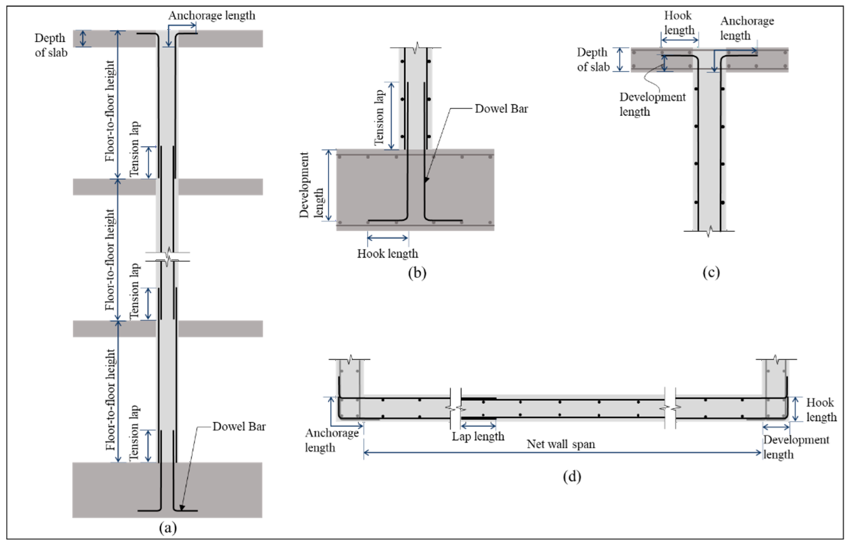
3. Identification of Factors Influencing Wall Rebar Usage and Cutting Waste
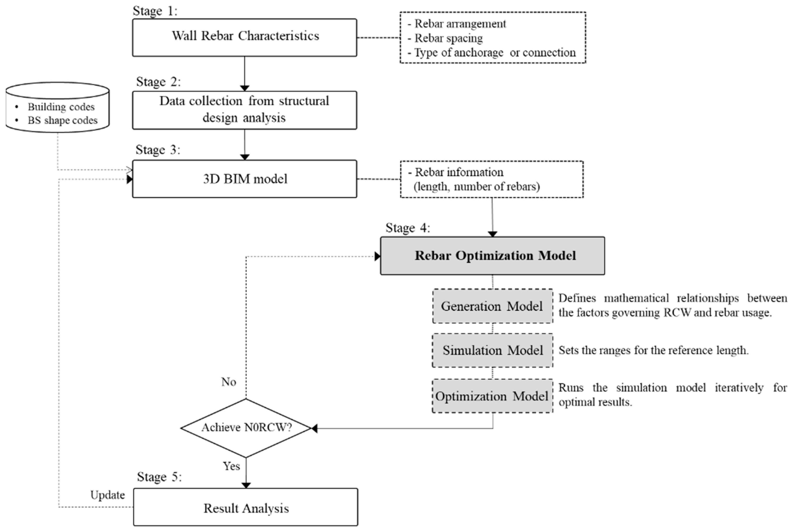
This research focused on wall rebar, necessitating an examination of its characteristics, in terms of arrangements of rebars that ensure the structural integrity and stability of the wall. These characteristics assist in identifying the factors that influence rebar usage and RCW in wall structures. In reinforced concrete (RC) buildings, structural walls function as the principal lateral load-resisting system, resisting wind and earthquake-induced forces and displacement [46]. The typical configuration of reinforcement in RC walls encompasses both vertical and horizontal steel bars, spaced and secured on both sides of the wall [32,47,48]. In order to withstand wind and seismic loads, any section of the wall should incorporate two layers of reinforcement, with each layer adhering to rebar spacing regulations to ensure structural integrity [35]. Notably, additional reinforcement is imperative at the corners of wall openings to prevent potential damage caused by opening moments [49]. Importantly, this study emphasizes the general case of walls without openings and does not consider additional rebar in such instances.
Figure 1a illustrates a common arrangement of vertical rebar in a general wall case. The dowel bar connects the foundation and the wall, as shown in Figure 1b. The main vertical rebar includes a lap splice on each floor level and an anchorage rebar with a 90° standard hook at the top floor slab (Figure 1c). For horizontal wall rebar arrangements, hook bars are commonly used to reinforce wall junctions, as demonstrated in Figure 1d. In addition to the general wall rebar arrangement, structural designers typically provide wider spacing with fewer rebars as the height of the wall increases from the bottom to the top of the building. Therefore, taller buildings have various rebar spacings along the wall reinforcement, resulting in a zone-by-zone arrangement of wall rebars based on similar spacing.
The arrangement of wall reinforcements has vertical and horizontal components spanning across the structure. The total length of the vertical reinforcements is influenced by several factors, including the length of the dowel bar, the floor-to-floor height of the building, the anchorage length, the lapping length, and the depth of the top floor slab. Similarly, the total length of the horizontal reinforcements is governed by the net wall span, the wall anchorage length, and the lapping length. These identified factors were used to develop the mathematical relationship of the optimization model for wall rebar usage.

4. Methodology

Figure 2 illustrates the stage-by-stage framework of the proposed method with the rebar optimization model.
Stage 1: The characteristics of wall rebar, including arrangement and spacing of rebar and type of anchorage, were analyzed to identify factors influencing RCW and rebar use.
Stage 2: Based on this analysis, the rebar information was collected from the structural design analysis or structural drawings.
Stage 3: A 3D BIM model was created to provide a visual representation of the wall panel and reinforcement. To ensure structural integrity, it is essential to verify structural design information and rebar specifications against building codes, including development length, lapping length, hook length, and rebar cover. Additionally, the BS shape code [44] was integrated into the BIM model to determine accurate rebar lengths. A set of rebar information was retrieved after the model was completed.
Stage 4: A rebar optimization model, which is the core of this study, was developed by adopting the modeling logic for the minimization of wall rebar. The aim of this model is to obtain the optimal RCW and rebar usage and the optimal reference length that will be used to determine the special-length rebar, considering the use of a 90° hook anchorage at the top of the building slab. The optimization model involves three models, which are briefly explained as follows:
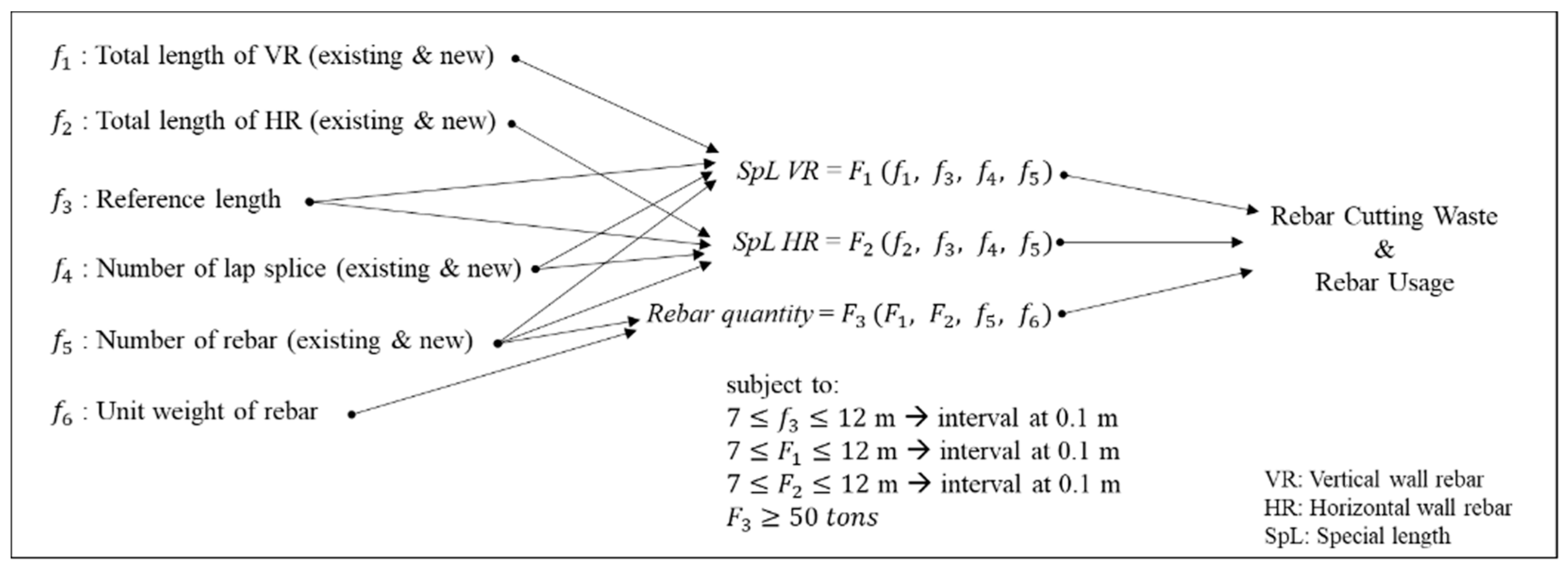
  • Generation model: Establishes the mathematical relationships between all governing factors affecting RCW and rebar usage.
  • Simulation model: Defines the ranges of factors, including reference length.
  • Optimization model: Iteratively runs the simulation model within constraints related to special-length rebar order requirements for optimal outcomes.
Stage 5: The effectiveness of the optimization model is validated by applying it to a specific wall panel case study and conducting a result analysis between the original design and the optimization model.
To ensure optimal rebar usage and achieve the target N0RCW, the model uses an iterative approach. If an initial optimization fails to meet N0RCW, a new optimization cycle is executed with a redefined reference length range. This process continues until N0RCW is successfully achieved. After reaching the target, the BIM model is updated with optimized rebar information, ensuring consistent data throughout the construction process.

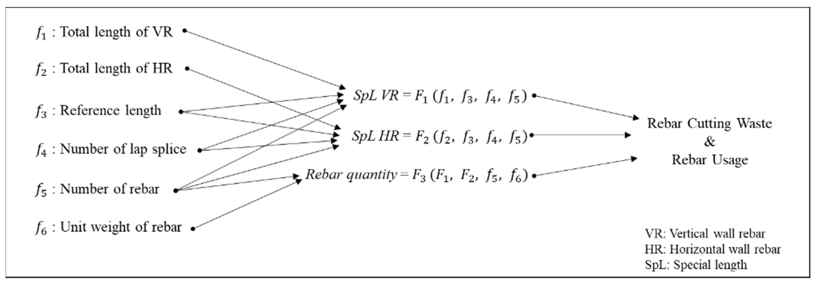
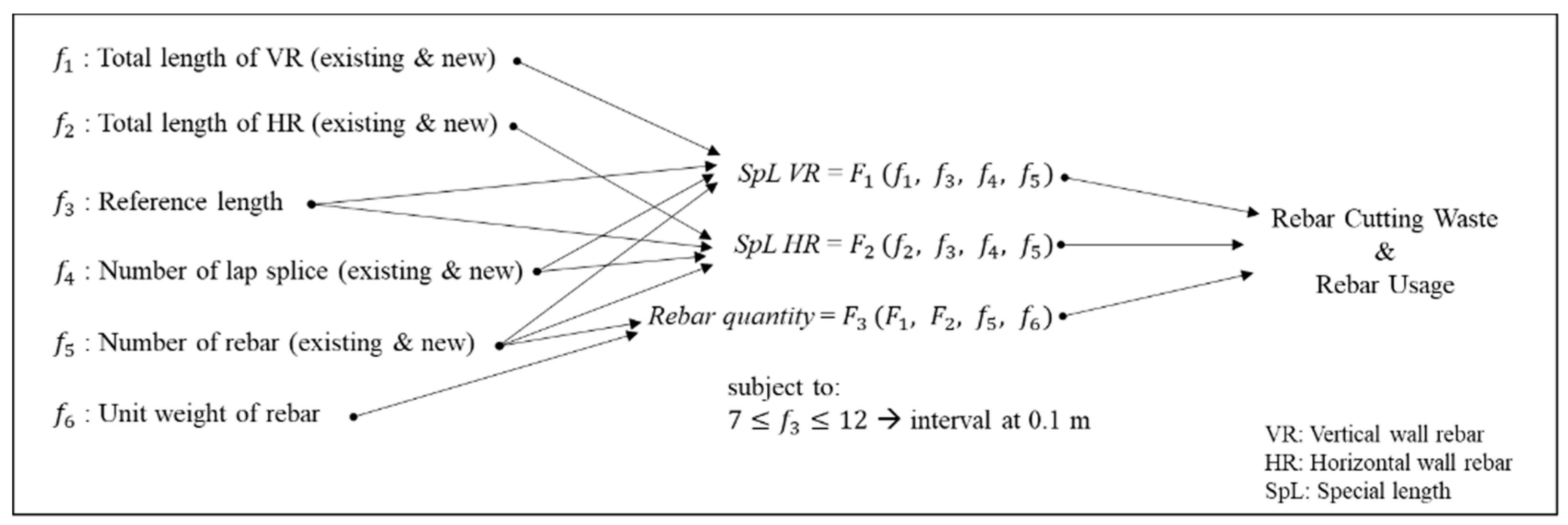
4.1. Rebar Optimization Model

4.1.1. Generation Model

In this model, all factors and functions related to RCW and rebar usage can be defined, as depicted in Figure 3. To calculate RCW and rebar usage, three functions were defined: special-length rebar for vertical reinforcement, special-length rebar for horizontal reinforcement, and rebar quantity for both reinforcements.
The first function was employed to determine the special-length rebar for vertical reinforcement of the walls. Numerous factors are involved in the calculation of special lengths for vertical reinforcement, including the total length of vertical reinforcement, the reference length, the number of lap splices, and the number of rebars. The total length of vertical reinforcement can be calculated using the variables identified in the previous section, as shown in Equation (1), adapted from Kim et al. [45]:
L V t o t a l h o o k = i = 1 l H f l o o r i + l d o w e l + l t a n c h o r + n l a p × l l a p D s l a b
where L V t o t a l h o o k is the total vertical length of the wall rebar for the hook case; i = 1 l H f l o o r i is the total floor height; l d o w e l is the length of the dowel bar; l t a n c h o r is the top anchorage length; n l a p is the number of lap splices; l l a p is the lapping length; and D s l a b is the depth of the top floor slab.
The length of the dowel bar was calculated by Equation (2) by combining the tension lap length, the rebar length in the foundation, and the hook length. The top anchorage was calculated by Equation (3) as the sum of the development length of the rebar in the top slab and the hook length [45]:
l d o w e l = l t e n s i o n   l a p + D f o u n d C f o u n d 2 × d b o t t o m + l h o o k
l t a n c h o r = l s l a b + l h o o k
where l t e n s i o n   l a p is the tension lap length; D f o u n d is the depth of the foundation; C f o u n d is the concrete cover of the foundation; d b o t t o m represents the diameter of the bottom rebar in the foundation; l h o o k represents the hook length; and l s l a b is the development length of the rebar in the top slab.
Upon obtaining the total vertical rebar length, the special length for vertical reinforcement can be obtained by the following steps, including reducing the number of lap splices and calculating the new total length. To reduce the number of splices in the existing method, which requires a lap splice at every floor level, the generated total lengths were divided by the reference length, yielding the required number of rebars. This calculation is given in Equation (4), which is adapted from Kim et al. [45]. The ceiling function was used to ensure that the rebar number was expressed as an integer.
n r e b a r = L t o t a l L r e f
where n r e b a r   represents the required number of rebars; L t o t a l   represents the total length of wall rebar (either vertical or horizontal); and L r e f   represents the reference length.
A reduction in the number of splices necessitates a recalculation of the total lengths to account for the revised number. This is achieved by substituting the updated number of lap splices into Equation (1), as demonstrated in Equation (5). The new number of splices is determined by subtracting 1 from the required number of rebars, as specified in Equation (4) for the top zone of the wall reinforcement. For the lower zones, the number of lap splices is the same as the number of rebars, since the protruding rebar length at the top of each lower zone is the lap splice.
N e w   L V t o t a l h o o k = i = 1 l H f l o o r i + l d o w e l + l t a n c h o r + n n e w   l a p × l l a p D s l a b
where N e w   L V t o t a l h o o k represents the new total vertical length of wall rebar for the hook case, and n n e w   l a p represents the new number of lap splices.
A special length is a customized rebar length that can be ordered by a customer. However, there are some specific requirements for special-length rebar orders, such as minimum and maximum lengths, minimum quantity, and preorder time. Special length can be calculated by dividing the new total length by the required number of rebars, as shown in Equation (6), adapted from Kim et al. [45]. The ceiling function is used to round up the special length to one decimal place since the purchased rebar is measured in 0.1 m intervals.
L s p e c i a l = N e w   L t o t a l n r e b a r
where L s p e c i a l represents the special length; N e w   L t o t a l represents the new total length of wall rebar (either vertical or horizontal); and n r e b a r represents the required number of rebars.
The calculation of the second function (special length for horizontal reinforcement of walls) follows a procedure similar to that for vertical reinforcement. The arrangement of horizontal wall rebar is illustrated in Figure 1d. The total horizontal length is derived from Equation (7) by considering the net wall span, two anchorage lengths at both ends, and the lapping length in the case of a lap splice. The wall anchorage is calculated as the combination of the development length of the rebar in the wall and the hook length, as shown in Equation (8) [45]:
L H t o t a l h o o k = l n e t + 2 × l w a l l a n c h o r + n l a p × l l a p
l w a l l a n c h o r = l w a l l + l h o o k
where L H t o t a l h o o k is the total horizontal length of wall rebar for the hook case; l n e t is the net wall span; l w a l l a n c h o r is the wall anchorage length; l l a p is the lapping length; n l a p is the number of lap splices; l w a l l is the development length of rebar in the wall; and l h o o k is the hook length.
The special length for horizontal reinforcement is determined using an approach similar to that for vertical reinforcement, as shown in Equations (4)–(6). However, in Equation (4), L t o t a l should be substituted with the total length for horizontal reinforcement, as defined in Equation (7). Subsequently, a reduction in the number of splices necessitates a recalculation of the total length to account for the new number. This is achieved by substituting the new number of lap splices into Equation (7), as shown in Equation (9):
N e w   L H t o t a l h o o k = l n e t + 2 × l w a l l a n c h o r + n n e w   l a p × l l a p
where N e w   L H t o t a l h o o k represents the new total horizontal length of wall rebar for the hook case and n n e w   l a p represents the new number of lap splices.
Finally, the special length can be obtained using Equation (6), by dividing the new total length for horizontal reinforcement by the required number of rebars.
Rebar quantity, represented by the third function, can be calculated by multiplying the unit weight of the rebar by the number and length of special-length rebars, as shown in Equation (10).
Q r e b a r = n t o t a l × L s p e c i a l × w r e b a r
where Q r e b a r is the total quantity of wall rebar; n t o t a l is the total number of required rebars; L s p e c i a l is the identified special length of rebar; and w r e b a r is the unit weight of rebar.

4.1.2. Simulation Model

This model defines the range of factors, including the reference length, as illustrated in Figure 4. The identified factors can be categorized into two types: conditional and fixed. As shown in Figure 4, the total length of vertical reinforcement, the total length of horizontal reinforcement, the number of lap splices, and the number of rebars are classified as conditional factors. Conversely, the rebar’s unit weight is considered as a fixed factor. Conditional factors, except the reference length and unit weight of rebar, contain both existing and new values. The reference length, employed to determine the special length, should be within the constraint expressed in Equation (11):
7 f 3 12   m ,   i n t e r v a l   a t   0.1

4.1.3. Optimization Model

In this model, the simulation model was run multiple times within the required constraints related to the special-length rebar order requirements to obtain the optimal results, as illustrated in Figure 5. There are some specific requirements for special-length rebar orders, including minimum and maximum lengths, minimum quantity, and preorder time. These conditions can differ depending on the country. In South Korea, an order for one special length must be at least 50 tons, with 0.1 m intervals and a preorder time of at least 2 months [18]. The minimum and maximum lengths were set at 7 and 12 m. All constraints are given in Equations (12)–(14):
7 F 1 12   m ,   i n t e r v a l   a t   0.1   m
7 F 2 12   m , i n t e r v a l   a t   0.1   m
F 3 50   t o n s

4.2. Termination Criteria and Result Analysis

A maximum loss rate of 1% was set, as the model aims to obtain the least rebar cutting waste with the optimum special length of rebar. If N0RCW was achieved, the process was verified by comparing it with the original design. Otherwise, new values were set, and the optimization process was repeated. The special lengths produced were used to procure materials from steel mills. Notably, no rebar was cut, since any excess served as additional length for hooks or lap splices. Consequently, the surplus length was regarded as a loss. Therefore, in this study, the cutting waste rate represents the wastage of rebar. Even though there was no cutting, the difference between the initial quantity required for construction and the purchased quantity was considered to be waste.
The loss rate is determined using Equation (15), which divides the difference between the total purchased and total required quantity of rebar by the total purchased quantity of rebar:
L o s s   r a t e = Q p u r Q r e q Q p u r × 100 %
where Q p u r is the purchased quantity and Q r e q is the required quantity of rebar.
The total required quantity ( Q r e q ) represents the quantity of rebar necessary for construction. This quantity is determined using the special rebar length before applying the ceiling function. Conversely, the total purchased quantity ( Q p u r ) is the quantity of rebar procured by the contractor from the steel mill. To calculate the purchased quantity, the ceiling value of the special-length rebar is employed.
The performance of the rebar optimization model was validated by comparing the cutting waste and rebar usage of the proposed model with the original design that uses stock-length rebar.

5. Analysis of the Optimization Model for Wall Rebar

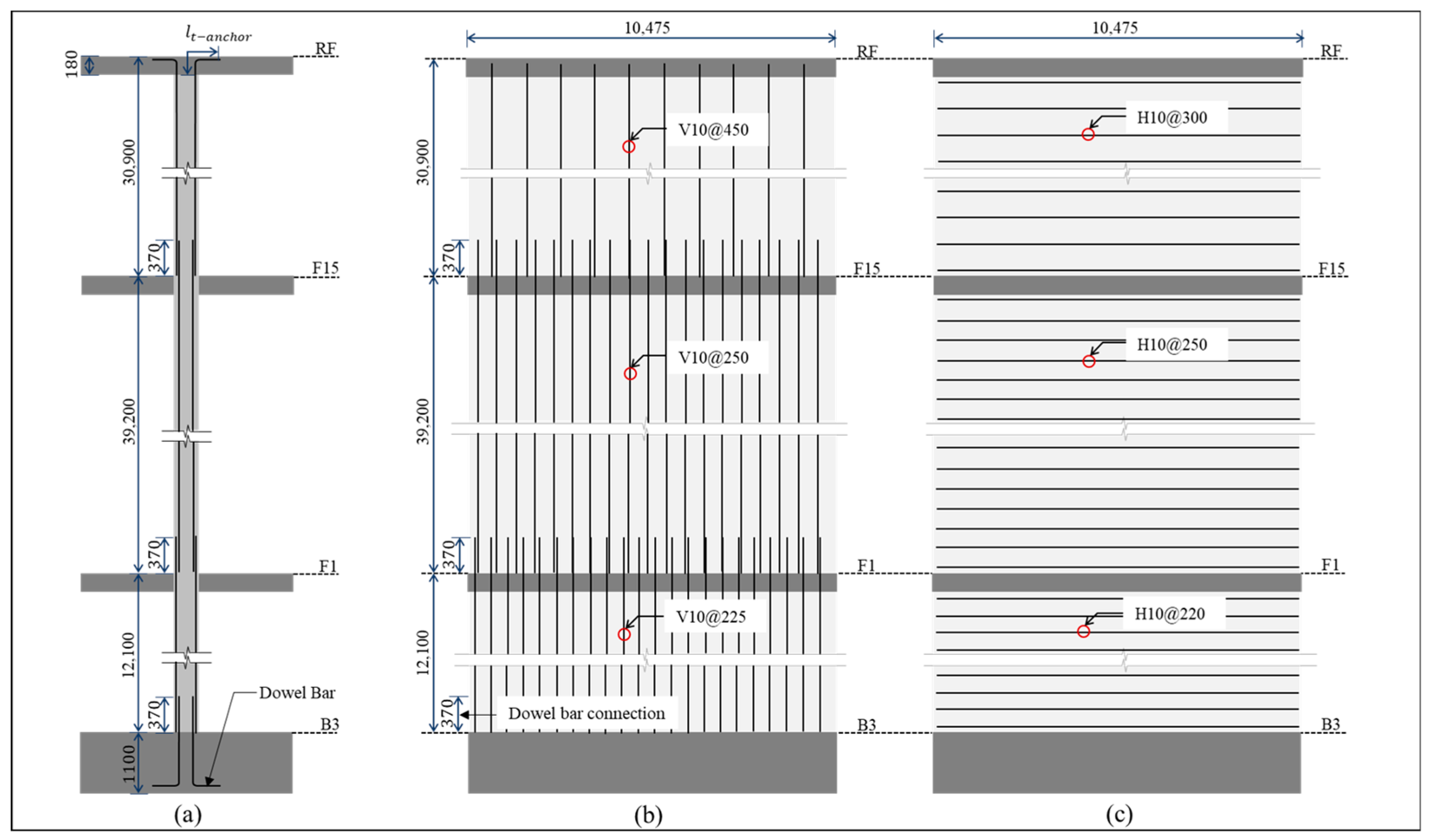
5.1. Case Study Application

The case study was an apartment building project with a bearing wall structure. The apartment had a total of 28 floors (three underground floors and 25 floors above ground level), with a maximum floor height of 5.1 m for the underground first floor and a standard floor height of 2.8 m. It had a building area of 3955.2 m2 and a total floor area of 103,977 m2, and was one of eight units in a land area of 32,141.4 m2. The details of the case study project are shown in Table 2. In addition, structural drawings of the case project include detailed structural information, including the wall schedule, rebar specifications, lapping length, and hook length.
Since the optimization model was developed based on the general case, which did not consider openings, a single wall panel was selected as the case wall to investigate its performance. The case wall, W1, extended throughout the entire building and connected with two other walls at both ends. The wall panel had an entire span of 10.475 m, with a thickness of 250 mm on the basement floors and 220 mm on the upper floors. The entire wall panel was reinforced vertically and horizontally with two layers of 10 mm rebar. The specific details and attributes of the case study wall are shown in Table 3.
The reinforcement of the wall was divided into three zones, each with distinct rebar spacing, as depicted in Figure 6a. The vertical rebar spacing varied as follows: 225 mm in zone B3–F1, 250 mm in zone F1–F15, and 450 mm in zone F15–RF, as shown in Figure 6b. Figure 6c shows three horizontal rebar spacings in the same zones: 220, 250, and 300 mm, respectively.

5.2. Model Application

First, a 3D BIM model was created with the information gathered from the case study’s 2D structural drawings. The 3D model allowed for visualization of the wall panel and reinforcement details. The 3D model was also applied with BS shape codes defining the total length of rebar. Due to the consistency of BIM, rebar information was updated through changes and could be retrieved from the 3D model.
In the first step of model application, the generation model was evaluated with the structural information for the case study wall, considering numerous factors (detailed in Section 4.1.1). Three functions were incorporated in the generation model to determine special vertical length, special horizontal length, and the corresponding quantities of rebar. These functions involved calculating mathematical equations for total vertical length, total horizontal length, number of required rebars, special length, and rebar quantity. The mathematical equation for total vertical length, Equation (1), was based on a continuous rebar arrangement. However, the case wall was divided into three zones based on rebar spacing, which necessitated an adjustment of the total length equation to reflect each zone’s rebar arrangement.
The total vertical and horizontal lengths of each zone were calculated using the information retrieved from the BIM model, taking into account the shape codes for rebar lengths such as the length of dowel bar, the top anchorage length, and the wall anchorage length. For the total vertical length of zone B3–F1, the total floor height from B3 to B1 was added to the length of the dowel bar, which was calculated using Equation (2), and the total lapping length. This resulted in a total height of 14.721 m. For zone F1–F15, the total floor height from F1 to F14 was added to the total lapping length, resulting in a total height of 44.380 m. For zone F15–RF, the total floor height from F15 to F25 was added to the total lapping length, the top anchorage length, which was calculated using Equation (3), and then the depth of the top slab was subtracted. This resulted in a total height of 34.699 m. Table 4 summarizes the calculation of total vertical lengths.
In the case of horizontal wall rebar, the total length was calculated by Equation (7) by combining the net span of the wall and two times the wall anchorage length, which was derived from Equation (8). This generated a total horizontal length of 10.674 m for zone B3–F1 and 10.694 m for zones F1–F15 and F15–RF. Table 5 summarizes the calculation of total horizontal length.
The second step of model application was the simulation model, with the reference length range defined as being between 7 and 12 m, as shown in Equation (11). To minimize rebar usage, the number of lap splices was reduced from the original design with a lap splice on every floor. This was executed by dividing the total lengths of vertical and horizontal wall rebars by the reference length, as shown in Equation (4), to generate the number of required rebars and the new number of lap splices. Once the lap splices were reduced, the total vertical lengths were recalculated for each zone using the new number to reflect the respective reference lengths.
Then, special lengths were calculated by Equation (6), and the quantities of special-length rebar were calculated by Equation (10). Consequently, the actual quantity of rebar required for the construction was compared to the purchased quantity of special-length rebar to determine the loss rate. The loss rate was calculated by Equation (15) for various special lengths generated by the given reference length range. Following the same calculation process from total lengths to special lengths, the simulation model was run 51 times within the given reference length range in 0.1 m intervals through Equations (4), (6), (10) and (15). The simulation results are presented in Table 6, comparing the generated vertical and horizontal special lengths of each zone and the overall loss rate for each reference length.
From Table 6, although reference lengths ranging from 7 to 7.3 m generated a loss rate of 0.98% (less than 1%), the resulting special lengths for both vertical and horizontal wall rebar were shorter than 7 m, which violated the special length constraints. Reference lengths between 7.4 and 10.6 m resulted in a loss rate greater than 1%, and not all special lengths met the established constraints. Additionally, it is worth noting that the lap splice was only provided when reference lengths shorter than 10.7 m were used for horizontal wall rebar, as depicted in Table 5. The loss rate was notably reduced starting with a reference length of 10.7 m, as no lap splice was required in horizontal reinforcement. Furthermore, it was observed that longer reference lengths in the range of 10.7 to 12 m produced special lengths with lower loss rates.
Subsequently, the optimization model was employed to determine the most efficient rebar usage and RCW, considering the constraints imposed by special length order requirements, such as minimum and maximum length, minimum rebar quantity, and preorder time. In South Korea, the minimum quantity of special-length rebar is 50 tons, with 0.1 m increments and preorder time of 2 months [18]. The constraints set for the special length order were defined by Equations (12)–(14). The minimum special length was set as 7 m, and the maximum as 12 m.
Among the simulation results with a loss rate of less than 1% (Table 6), reference lengths of 11.6, 11.7, 11.8, 11.9, and 12 m generated the same special lengths for zones with a loss rate of 0.18%. Vertical special lengths were 7.2 m for B3–F1, 10.2 m for F1–F15, and 10.6 m for F15–RF, and the horizontal special length was 10.7 m for all zones, satisfying the special length constraints. Because 12 m is the longest market length of rebar offered by steel mills in South Korea, 12 m was considered as the optimal reference length, yielding special lengths with minimum rebar usage and RCW. Table 7 shows the results of calculating special lengths for vertical and horizontal wall rebar using a reference length of 12 m.

5.3. Verification of the Model

To validate the effectiveness of the optimization model, it was essential to compare the model-generated rebar quantities with those of the original design. The required and purchased rebar quantities in the original design were calculated based on the assumption that only stock-length rebar would be purchased. The calculation results of the original case are summarized in Appendix A, Table A1. Table 8 compares the rebar usage and RCW for the original design and the optimization model proposed in this study. When stock-length rebar was used, 8.494 tons of rebar was required, generating a waste rate (RCW) of 13.19%. In contrast, using special-length rebar produced a waste rate of 0.18% with a purchased quantity of 7.122 tons, achieving N0RCW. The optimization model further reduced the initial rebar quantity by 0.265 tons (3.59%) from the original case by reducing the number of lap splices and incorporating special lengths. In addition, rebar consumption was reduced by 16.16%, saving 1.373 tons of rebar in a single wall panel. Therefore, it was sufficiently verified that the reference length of 12 m obtained by the optimization model yields optimal rebar usage and cutting waste.

6. Discussion

This study developed a rebar optimization model to minimize rebar usage and RCW of wall reinforcement by reducing the number of splices, utilizing special-length rebar, and determining the optimal reference length for special-length rebar. A few observations were made after applying the proposed model:
(1)
The model confirmed that a 12 m reference length is optimal for determining special-length rebar with the least cutting waste. In Korea, 12 m is the maximum rebar length that steel mills can provide. Since a longer reference length can generate a smaller number of rebars, it corresponds to a lower loss rate (0.18%) and rebar usage. This study addresses a critical gap in the literature regarding reference length for special-length rebar in wall elements, and contributes valuable insights into rebar waste management in relatively uncomplicated structures.
(2)
While it has been demonstrated that using special rebar lengths and reducing lap splices can effectively decrease rebar usage, it is essential to ensure that the quantity of special-length rebar meets the minimum order requirements. The total rebar quantity generated by the proposed model was 7.122 tons, which did not meet the special-order quantity of 50 tons. However, this study was conducted for a general case of a single wall, and the case project was a joint housing project that included eight building blocks, each with an average of 28 floors, including basements. If the proposed model was applied to all walls with rebar arrangements similar to that of the case project, it would generate notable RCW and rebar usage, and would conform to the minimum quantity of special-length rebar ordered.
(3)
Mathematical equations for total length calculation were developed based on a continuous rebar arrangement from the bottom to the top of the wall panel. However, the reinforcement of the case study wall was organized into three rebar spacings vertically and horizontally. Therefore, the total length calculations needed to be adjusted based on the zone to account for the rebar arrangement with uniform spacing.
(4)
In addition to the rebar arrangement, the configuration and position of the wall also impacted the calculation of total length. The case wall panel was situated between two walls, and the equation for the total horizontal rebar length was developed based on this specific wall position. Consequently, the model needs to be modified when applied to other wall positions.
(5)
The proposed model primarily addressed scenarios in which rebar is continuously arranged along the entire span of the wall without openings. Therefore, it has limitations when applied to walls with openings. In such cases, the optimization process must be adjusted and modified to account for the locations of the openings and the rebar arrangement. Subsequently, the various remaining rebars generated by the openings and additional bars at the corners must be incorporated into a cutting pattern that generates the least RCW.
(6)
The case wall panel in this study used a small rebar size of 10 mm, whereas large wall structures such as shear walls, retaining walls, and diaphragm walls require larger rebar sizes. In such situations, mechanical couplers can be used to replace lap splices to prevent rebar congestion and enhance structural integrity. In future studies, the proposed algorithm could be adapted to consider the use of mechanical couplers.
This study additionally delved into the application of standard hooks in the wall reinforcement, particularly focusing on the scenario where a hook is used to anchor the upper part of the wall reinforcement. In South Korea, a region characterized by low seismic activity, where the seismic performance of buildings is not as critical as in regions with higher seismic activity, the use of U-bars is preferred over hooks due to their convenient installation in construction. In such a case, the simulation model should be considered an additional function for combining rebars to produce the minimal loss rate.

7. Conclusions

The main purpose of this study was to develop a rebar optimization model that reduces the waste associated with cutting rebar for walls, optimizes wall rebar usage, and determines the optimal reference length of special-length rebar. This was achieved by taking special rebar lengths into account and reducing the number of lap splices. The model was applied to a case study of a wall in a 28-floor building, which had vertical wall reinforcement arranged in three rebar spacings. The vertical reinforcement was divided into three zones, and the equations for total vertical length were adjusted according to the rebar placement in each zone. A case study was conducted with 90° standard hooks as top anchorage. The key findings are as follows.
  • Optimal reference length: The model confirmed that a 12 m reference length, corresponding to the maximum length of steel mill supplied rebar, is the most efficient length.
  • Rebar cutting waste: By using the optimal reference length of 12 m, the model generated a total purchased special-length rebar quantity of 7.122 tons with an RCW/loss rate of 0.18%, achieving N0RCW. In contrast, the existing method, which employs stock-length rebar, required 8.494 tons and had an RCW rate of 13.19%.
  • Rebar usage: The proposed model reduced the required rebar quantity by 0.265 tons (3.59%) and the purchased quantity by 1.373 tons (16.16%) when special lengths and reduced lap splices were taken into consideration.
It has been confirmed by many studies that using special lengths facilitates minimal rebar usage and reduces cutting waste in construction projects. The optimization model in this study also verified that the 12 m reference length is the most efficient for generating special lengths. However, there are practical limitations regarding special length orders, such as minimum quantity and preorder time for one special length, leading to limited adoption by large-scale projects. To promote the use of special lengths and to realize the benefits of the proposed algorithm, steel mills should consider making their requirements for special length orders more flexible.
The proposed model demonstrated a significant reduction in rebar consumption compared to the existing method, which employs stock-length rebar. It is expected that the proposed model can serve as an N0RCW optimization model for wall rebar. The authors recommend that future studies explore various wall configurations, including walls with openings, as well as the U-bar case. Additionally, mechanical couplers can eliminate the amount of rebar required for lap splices, thereby reducing rebar consumption. Since mechanical couplers are not recommended for wall rebar with a diameter smaller than 19 mm, future studies could enhance the proposed model by incorporating couplers suitable for wall rebar in large-scale construction projects such as urban housing, tunnels, subways, and bridges, which consume substantial amounts of large-diameter rebar. This study can assist engineers and the construction industry in recognizing the benefits of special lengths to optimize efficiency and reduce construction waste, which contributes to sustainable construction practices. Additionally, it provides useful insights for fellow researchers and students, offering a practical understanding of how to enhance rebar usage for wall rebar in various construction projects.

Author Contributions

Conceptualization, S.K.; methodology, S.K. and D.-J.K.; validation, S.K., D.-J.K., L.P.K. and D.D.W.; formal analysis, D.-J.K., L.P.K. and D.D.W.; investigation, L.P.K. and D.D.W.; resources, S.K. and D.-J.K.; data curation, L.P.K.; writing—original draft preparation, D.-J.K., L.P.K. and D.D.W.; writing—review and editing, S.K., D.-J.K., L.P.K. and D.D.W.; supervision, S.K.; project administration, D.-J.K.; funding acquisition, S.K. All authors have read and agreed to the published version of the manuscript.

Funding

This study was supported by National Research Foundation of Korea (NRF) grants funded by the government of the Republic of Korea (MOE) (No. 2022R1A2C2005276).

Data Availability Statement

The data supporting the findings of this study are available from the corresponding authors upon reasonable request.

Conflicts of Interest

The authors declare no conflicts of interest.

Notations

Variables and functions
L V t o t a l h o o k Total vertical wall rebar length for hook case (m)
H f l o o r i Total floor height (m)
l d o w e l Length of dowel bar (m)
l t a n c h o r Top anchorage length (m)
n l a p Number of lap splices (pcs)
l l a p Lapping length (m)
l t e n s i o n   l a p Tension lap length (m)
D f o u n d Depth of foundation (m)
C f o u n d Concrete cover of foundation (mm)
d b o t t o m Diameter of bottom rebar (mm)
l h o o k Rebar hook length (m)
l s l a b Development length of rebar in top slab (m)
n r e b a r Required number of rebars (pcs)
L t o t a l Total length of vertical or horizontal wall rebar (m)
L r e f Reference length (m)
N e w   L V t o t a l h o o k New total vertical wall rebar length for hook case (m)
n n e w   l a p New number of lap splices (pcs)
L s p e c i a l Special length (m)
L H t o t a l h o o k Total horizontal wall rebar length for hook case (m)
l n e t Net wall span (m)
l w a l l a n c h o r Wall anchorage length (m)
l w a l l Development length of rebar in wall (m)
N e w   L H t o t a l h o o k New total horizontal wall rebar length for hook case (m)
Q r e b a r Total wall rebar quantity (tons)
n t o t a l Total number of required rebars (pcs)
w r e b a r Rebar unit weight (kg/m)
L o s s   r a t e Loss rate including cutting waste (%)
Q p u r Purchased rebar quantity (tons)
Q r e q Required rebar quantity (tons)

Appendix A

Table A1. Calculation results for original design using stock-length rebar.
DescriptionTotal Length (m)No. of Rebars in Wall PanelStock Length (m)No. of RebarsRequired Quantity (tons)Purchased Quantity (tons)RCW Rate (%)
VR (B3–F1)14.721901220.7421.21038.66%
VR (F1–F15)44.380821242.0382.2047.54%
VR (F15–RF)34.699461230.8940.9273.61%
HR (B3–F1)10.6741101210.6580.73911.05%
HR (F1–F15)10.6943081211.8442.07010.89%
HR(F15–RF)10.6942001211.1981.34410.89%
7.3738.49413.19%

References

  1. Wu, H.; Hu, R.; Yang, D.; Ma, Z. Micro-macro Characterizations of Mortar Containing Construction Waste Fines as Replacement of Cement and Sand: A comparative study. Constr. Build. Mater. 2023, 383, 131328. [Google Scholar] [CrossRef]
  2. Hernandez, G.; Low, J.; Nand, A.; Bu, A.; Wallis, S.L.; Kestle, L.; Berry, T. Quantifying and Managing Plastic Waste Generated from Building Construction in Auckland, New Zealand. Waste Manag. Res. J. Sustain. Circ. Econ. 2023, 41, 205–213. [Google Scholar] [CrossRef] [PubMed]
  3. Rondinel-Oviedo, D.R. Construction and Demolition Waste Management in Developing Countries: A Diagnosis from 265 Construction Sites in the Lima Metropolitan Area. Int. J. Constr. Manag. 2021, 23, 371–382. [Google Scholar] [CrossRef]
  4. Wu, Z.; Yu, A.T.W.; Poon, C.S. An Off-site Snapshot Methodology for Estimating Building Construction Waste Composition—A Case Study of Hong Kong. Environ. Impact Assess. Rev. 2019, 77, 128–135. [Google Scholar] [CrossRef]
  5. Kwon, K. A Study on the Development of Optimization Algorithms for Near Zero Cutting Wastes of Reinforcement Steel Bars. Ph.D. Thesis, Kyung Hee University, Yongin, Republic of Korea, 2023. [Google Scholar]
  6. Datta, S.D.; Rana, J.; Assafi, M.N.; Mim, N.J.; Ahmed, S. Investigation on the Generation of Construction Wastes in Bangladesh. Int. J. Constr. Manag. 2023, 23, 2260–2269. [Google Scholar] [CrossRef]
  7. Miller, S.A.; Horvath, A.; Monteiro, P.J. Readily Implementable Techniques Can Cut Annual CO2 Emissions from the Production of Concrete by over 20%. Environ. Res. Lett. 2016, 11, 074029. [Google Scholar] [CrossRef]
  8. Kim, K.; Jeon, Y.; Park, Y.J.; Park, S. Sustainable Anti-Tank Obstacle System Applying Civil-Military Cooperation in Highly Urbanized Areas. Sustainability 2022, 14, 12715. [Google Scholar] [CrossRef]
  9. Lee, I.J.; Yu, H.; Chan, S.L. Carbon Footprint of Steel-Composite and Reinforced Concrete Buildings, Standing Committee on Concrete Technology Annual Concrete Seminar, Hong Kong, Construction Industry Council, 2016. Available online: https://www.devb.gov.hk/filemanager/en/content_971/7_Carbon_Footprint_for_Steel_Composite_and_Reinforced_Concrete_Buildings.pdf (accessed on 20 June 2023).
  10. Benjaoran, V.; Bhokha, S. Three-step solutions for cutting stock problem of construction steel bars. KSCE J. Civ. Eng. 2014, 18, 1239–1247. [Google Scholar] [CrossRef]
  11. Chen, Y.; Yang, T. Lapping Pattern, Stock Length, and Shop Drawing of Beam Reinforcements of an RC Building. J. Comput. Civ. Eng. 2015, 29, 04014028. [Google Scholar] [CrossRef]
  12. Nadoushani, Z.S.M.; Hannad, A.W.; Xiao, J.; Akbarnezhad, A. Minimizing cutting wastes of reinforcing steel bars through optimizing lap splicing within reinforced concrete elements. Constr. Build. Mater. 2018, 185, 600–608. [Google Scholar] [CrossRef]
  13. Zheng, C.; Yi, C.; Lu, M. Integrated optimization of rebar detailing design and installation planning for waste reduction and productivity improvement. Autom. Constr. 2019, 101, 32–47. [Google Scholar] [CrossRef]
  14. Khondoker, M.T.H. Automated reinforcement trim waste optimization in RC frame structures using building information modeling and mixed integer linear programming. Autom. Constr. 2021, 124, 103599. [Google Scholar] [CrossRef]
  15. Zubaidy, D.S.; Dawood, S.Q.; Khalaf, I.D. Optimal Utilization of Rebar Stock for Cutting Processes in Housing Project. Int. J. Adv. Res. Sci. Eng. Technol. 2016, 3, 189–193. [Google Scholar] [CrossRef]
  16. Widjaja, D.D.; Rachmawati, T.S.N.; Kwon, K.; Kim, S. Investigating Structural Stability and Constructability of Buildings Relative to the Lap Splice Position of Reinforcing Bars. J. Korea Inst. Build. Constr. 2023, 23, 315–326. [Google Scholar] [CrossRef]
  17. Almeida, J.P.; Prodan, O.; Tarquini, D.; Beyer, K. Influence of Lap Splices on the Deformation Capacity of RC Walls. I: Database Assembly, Recent Experimental Data, and Findings for Model Development. J. Struct. Eng. 2017, 143, 04017156. [Google Scholar] [CrossRef]
  18. Lee, D.; Son, S.; Kim, D.; Kim, S. Special-Length-Priority Algorithm to Minimize Reinforcing Bar-Cutting Waste for Sustainable Construction. Sustainability 2020, 12, 5950. [Google Scholar] [CrossRef]
  19. Porwal, A.; Hewage, K.N. Building information modeling based analysis to minimize the waste rate of structural reinforcement. J. Constr. Eng. Manag. 2012, 138, 943–954. [Google Scholar] [CrossRef]
  20. Widjaja, D.D.; Kim, S. Reducing rebar cutting waste and rebar usage of beams: A two-stage optimization algorithm. Buildings 2023, 13, 2279. [Google Scholar] [CrossRef]
  21. Rachmawati, T.S.; Kim, S. A risk management model of apartment development projects using system dynamics. J. Asian Arch. Build. Eng. 2022, 22, 1492–1506. [Google Scholar] [CrossRef]
  22. Ma, Z.; Zhao, Q.; Cang, T.; Li, Z.; Zhu, Y.; Hei, X. An Intelligent Optimization Method of Reinforcing Bar Cutting for Construction Site. Comput. Model. Eng. Sci. 2023, 134, 637–655. [Google Scholar] [CrossRef]
  23. Rahimi, Z.; Maghrebi, M. Minimizing rebar cost using design and construction integration. Autom. Constr. 2023, 147, 104701. [Google Scholar] [CrossRef]
  24. Burgan, B.; Sansom, M. Sustainable steel construction. J. Constr. Steel Res. 2006, 62, 1178–1183. [Google Scholar] [CrossRef]
  25. Tingley, D.; Davison, B. Minimizing the Environmental Impact of Steel Structures, Design, Fabrication and Economy of Metal Structures; Springer: Berlin/Heidelberg, Germany, 2013; pp. 651–656. [Google Scholar] [CrossRef]
  26. Khalifa, Y.; Salem, O.; Shahin, A. Cutting Stock Waste Reduction Using Genetic Algorithms. In Proceedings of the 8th Annual Conference on Genetic and Evolutionary Computation, Seattle, WA, USA, 8–12 July 2006; pp. 1675–1680. [Google Scholar] [CrossRef]
  27. Zheng, C.; Lu, M. Optimized Reinforcement Detailing Design for Sustainable Construction: Slab Case Study. Procedia Eng. 2016, 145, 1478–1485. [Google Scholar] [CrossRef]
  28. Nanagiri, Y.V.; Singh, R.K. Reduction of Wastage of Rebar by Using BIM and Linear Programming. Int. J. Technol. 2015, 5, 329. [Google Scholar] [CrossRef]
  29. Salem, O.; Shahin, A.; Khalifa, Y. Minimizing Cutting Wastes of Reinforcement Steel Bars Using Genetic Algorithms and Integer Programming Models. J. Constr. Eng. Manag. 2007, 133, 982–992. [Google Scholar] [CrossRef]
  30. Nadoushani, Z.S.; Hammad, A.W.A.; Akbarnezhad, A.A. Framework for Optimizing Lap Splice Positions within Concrete Elements to Minimize Cutting Waste of Steel Bars. In Proceedings of the 33rd International Symposium on Automation and Robotics in Construction (ISARC), Auburn, AL, USA, 18–21 July 2016. [Google Scholar]
  31. Najafgholipour, M.A.; Dehghan, S.M.; Khani, M.; Heidari, A. The Performance of Lap Splices in RC Beams under Inelastic Reversed Cyclic Loading. Structures 2018, 15, 279–291. [Google Scholar] [CrossRef]
  32. ACI Committee 318; Building Code Requirements for Structural Concrete (ACI 318-19) and Commentary (ACI 318R-19). American Concrete Institute: Farmington Hills, MI, USA, 2019.
  33. KDS 14 20 52; Concrete Structure-Joint Design Criteria, 18. Ministry of Land, Infrastructure, and Transportation: Sejong, Republic of Korea, 2021.
  34. Japan Society of Civil Engineers. Standard Specifications for Concrete Structures–2007 “Design” in JSCE Guidelines for Concrete, No.15 469; Japan Society of Civil Engineers: Tokyo, Japan, 2010. [Google Scholar]
  35. BS 8110:1997; Structural Use of Concrete-Part 1, Code of Practice for Design and Construction. British Standards Institution: London, UK, 1997.
  36. Khosakitchalert, C.; Yabuki, N.; Fukuda, T. Automated modification of compound elements for accurate BIM-based quantity take off. Autom. Constr. 2020, 113, 103142. [Google Scholar] [CrossRef]
  37. Jack, C.P.; Chan, C.M.; Gan, V. BIM-Based Rebar Design Optimization and Prefabrication Automation. (n.d.-a). The Hong Kong University of Science and Technology (HKUST) 21 August 2020. Available online: http://www.hkcma.asia/upload/seminar/m/2/00000000013.pdf (accessed on 4 January 2024).
  38. Won, J.; Cheng, J.C.P.; Lee, G. Quantification of construction waste prevented by BIM-based design validation: Case studies in South Korea. Waste Manag. 2016, 49, 170–180. [Google Scholar] [CrossRef]
  39. Chuck, E.; Paul, T.; Rafael, S.; Kathleen, L. BIM Handbook, A Guide to Building Information Modeling for Owners, Managers, Designers, Engineers, and Contractors, 2nd ed.; John Wiley & Sons, Inc.: Hoboken, NJ, USA, 2011. [Google Scholar]
  40. Zheng, J.; Fischer, M. BIM-GPT: A Prompt-Based Virtual Assistant Framework for BIM Information Retrieval. arXiv 2023, arXiv:2304.09333. [Google Scholar] [CrossRef]
  41. Rane, N.L.; Choudhary, S.P.; Rane, J. Integrating Building Information Modelling (BIM) with ChatGPT, Bard, and Similar Generative Artificial Intelligence in the Architecture, Engineering, and Construction Industry: Applications, a Novel Framework, Challenges, and Future Scope. SSRN Electron. J. 2023. Available online: https://www.semanticscholar.org/paper/Integrating-Building-Information-Modelling-(BIM)-in-Rane-Choudhary/ce5555efa9375a8d40021a1a9e1429b5b0021b7a (accessed on 18 January 2024). [CrossRef]
  42. Nigussie, T.; Chandrasekar, M.K. Influence of rebar practice in the total cost of building construction projects: The case of Hawassa City, Ethiopia. Int. J. Eng. Sci. Technol. 2020, 12, 54–65. [Google Scholar] [CrossRef]
  43. Surve, R.B.; Kulkarni, S.S. Construction waste reduction—A case study. Int. J. Eng. Res. Technol. 2013, 2, 870–875. [Google Scholar]
  44. BS 8666; Scheduling, Dimensioning, Cutting and Bending of Steel Reinforcement for Concrete; Specification. British Standards Institution: London, UK, 2020.
  45. Kim, D.; Suh, S.; Kim, S.; Lwun, P.K. Development of an Algorithm for the Automatic Quantity Estimation of Wall Rebar. Korean J. Constr. Eng. Manag. 2023, 24, 83–94. [Google Scholar] [CrossRef]
  46. Hoult, R.D.; de Almeida, J.P. Residual displacements of reinforced concrete walls detailed with conventional steel and shape memory alloy rebars. Eng. Struct. 2022, 256, 114002. [Google Scholar] [CrossRef]
  47. Jarkas, A.M. Analysis and Measurement of Buildability Factors Influencing Rebar Installation Labor Productivity of In Situ Reinforced Concrete Walls. J. Arch. Eng. 2012, 18, 52–60. [Google Scholar] [CrossRef]
  48. Darwin, D.; Dolan, C.W.; Nilson, A.H. Design of Concrete Structures, 15th ed.; McGraw-Hill: New York, NY, USA, 2016; pp. 179–187. [Google Scholar]
  49. Moretti, M.; Tassios, T.; Vintzileou, E. Behavior and Design of Corner Joints under Opening Bending Moment. ACI Struct. J. 2014, 111, 3–14. [Google Scholar] [CrossRef]
Figure 1. Characteristics of wall rebar: (a) typical arrangement of vertical wall reinforcement; (b) dowel bar at foundation; (c) top anchorage rebar with hook at top slab; (d) hooks at wall connections (adapted from Kim et al. [45]).
Buildings 14 00290 g001
Figure 2. Flowchart of methodology.
Buildings 14 00290 g002
Figure 3. Generation model.
Buildings 14 00290 g003
Figure 4. Simulation model.
Buildings 14 00290 g004
Figure 5. Optimization model.
Buildings 14 00290 g005
Figure 6. Rebar arrangement of case wall: (a) cross-section of vertical rebar placement; (b) vertical rebar spacing; (c) horizontal rebar spacing (adapted from Kim et al. [45]).
Buildings 14 00290 g006
Table 1. Approaches in the literature for reducing rebar cutting waste.
Related TopicsFindingsDrawbacksReferences
Stock length-based rebar cutting waste optimization
-
Optimum cutting patterns were obtained.
-
Rebar cutting waste was reduced.
-
Diverse structural members (RC frames, slab) were covered.
-
Reduced cutting waste appears to be higher than 1%.
-
Focus is on optimizing cutting pattern instead of minimizing number of rebars to be cut.
[13,14,15,26,27,28,29]
Lap splice position optimization with adherence to lap splice position regulation using stock-length rebar
-
Reduced cutting waste was achieved while maintaining compliance with splicing regulations for rebar.
-
Method was applied to beam, column, and shear walls.
-
Regulation limits reduction rate of cutting waste, leading to greater than 1% waste.
-
Difficult for sites and workers to follow regulations.
[11,12,30]
Special-length rebar approach
-
Cutting waste was notably reduced to near zero by combining special length with stock-length rebar.
-
Approach was applied to RC frames.
-
Constraints were not clearly defined.
-
Focus is on optimizing cutting pattern instead of minimizing number of rebars to be cut.
[18,19]
Lap splice position impact analysis
-
Lap splice can be placed beyond designated position.
-
Requires more experiments to further validate findings.
[16]
Special-length rebar approach without strict adherence to lap splice position regulation
-
Cutting waste was notably reduced to near zero (<1%) by using special-length rebar.
-
Approach was applied to both continuous and discontinuous rebar of the beam.
-
Reference length used to determine special-length rebar was unclear.
[20]
Table 2. Description of case study project.
DescriptionContent
LocationGyeonggi-do
Project typeJoint housing
Land area32,141.4 m2
Building area3955.2 m2, 8 units
Gross floor area (floor area ratio)103,977 m2 (323.5%)
Number of floors3 basement floors, 25 floors above
Floor height2.8–5.1 m
Building structural typeBearing wall structure
Table 3. Attributes of case wall, W1.
DescriptionValue
Entire wall span10.475 m
Floor height (B3, B2)3.5 m
Floor height (B1)5.1 m
Floor height (F1–F24)2.8 m
Floor height (F25)2.9 m
Depth of foundation ( D f o u n d )1100 mm
Concrete cover for foundation ( C f o u n d )70 mm
Foundation bottom rebar ( d b o t t o m )19 mm
Depth of floor slab ( D s l a b )180 mm
Concrete cover for wall/slab40 mm
Concrete cover for basement wall50 mm
Strength and diameter of wall rebar10 mm (SHD500)
Class B tension lap length370 mm
Hook length170 mm
Unit weight of rebar0.56 kg/m
Concrete strength24 MPa
Table 4. Calculation of total vertical length.
Zone l d o w e l (mm) l t a n c h o r (mm) H (mm)No. of Laps l l a p (mm)Total Length (m)
B3–B1F1–F14F15–F25
B3–F11511.4012,100--337014.721
F1–F1500-39,200-1437044.380
F15–RF0279.4--30,9001037034.699
Table 5. Calculation of total horizontal length.
Zone l w a l l a n c h o r (mm) l n e t (mm)Total Length (m)
B3–F1349.4997510.674
F1–F15309.410,07510.694
F15–RF309.410,07510.694
Table 6. Analysis of simulation model results.
Reference Length (m)Special Length (m)RCW/Loss Rate (%)
VR (B3–F1)VR (F1–F15)VR (F15–RF)HR (B3–F1)HR (F1–F15)HR (F15–RF)
7566.55.65.65.60.98%
7.1566.55.65.65.60.98%
7.2566.55.65.65.60.98%
7.3566.55.65.65.60.98%
7.47.276.55.65.65.61.06%
7.57.276.55.65.65.61.06%
7.67.276.55.65.65.61.06%
7.77.276.55.65.65.61.06%
7.87.276.55.65.65.61.06%
7.97.276.55.65.65.61.06%
87.27.06.55.65.65.61.06%
8.17.27.06.55.65.65.61.06%
8.27.27.06.55.65.65.61.06%
8.37.27.06.55.65.65.61.06%
8.47.27.06.55.65.65.61.06%
8.57.27.06.55.65.65.61.06%
8.67.27.06.55.65.65.61.06%
8.77.27.08.15.65.65.61.15%
8.87.27.08.15.65.65.61.15%
8.97.28.38.15.65.65.61.08%
97.28.38.15.65.65.61.08%
9.17.28.38.15.65.65.61.08%
9.27.28.38.15.65.65.61.08%
9.37.28.38.15.65.65.61.08%
9.47.28.38.15.65.65.61.08%
9.57.28.38.15.65.65.61.08%
9.67.28.38.15.65.65.61.08%
9.77.28.38.15.65.65.61.08%
9.87.28.38.15.65.65.61.08%
9.97.28.38.15.65.65.61.08%
107.28.38.15.65.65.61.08%
10.17.28.38.15.65.65.61.08%
10.27.28.38.15.65.65.61.08%
10.37.28.38.15.65.65.61.08%
10.47.28.38.15.65.65.61.08%
10.57.28.38.15.65.65.61.08%
10.67.28.38.15.65.65.61.08%
10.77.28.38.110.710.710.70.47%
10.87.28.38.110.710.710.70.47%
10.97.28.38.110.710.710.70.47%
117.28.38.110.710.710.70.47%
11.17.210.28.110.710.710.70.26%
11.27.210.28.110.710.710.70.26%
11.37.210.28.110.710.710.70.26%
11.47.210.28.110.710.710.70.26%
11.57.210.28.110.710.710.70.26%
11.67.210.210.610.710.710.70.18%
11.77.210.210.610.710.710.70.18%
11.87.210.210.610.710.710.70.18%
11.97.210.210.610.710.710.70.18%
127.210.210.610.710.710.70.18%
Table 7. Special lengths calculated based on reference length of 12 m.
DescriptionNew Total Length (m)No. of Rebars No. of Rebars in Wall PanelCalculated Length (m)Special Length (m)Required Quantity (ton)Purchased Quantity (ton)RCW/Loss Rate (%)
VR (B3–F1)14.3512907.1767.20.7230.7260.34%
VR (F1–F15)40.68048210.17010.21.8681.8740.29%
VR (F15–RF)31.73934610.58010.60.8180.8190.19%
HR (B3–F1)10.674111010.67410.70.6580.6590.24%
HR (F1–F15)10.694130810.69410.71.8441.8460.06%
HR (F15–RF)10.694120010.69410.71.1981.1980.06%
7.1097.1220.18%
Table 8. Analysis of rebar quantities and cutting waste between original design and optimization model.
Required Quantity (tons)Purchase Quantity (tons)RCW/Loss Rate (%)
OriginalOptimization ModelDifference OriginalOptimization ModelDifference OriginalOptimization ModelDifference
7.3737.1090.2658.4947.1221.37313.19%0.18%13.01%
Disclaimer/Publisher’s Note: The statements, opinions and data contained in all publications are solely those of the individual author(s) and contributor(s) and not of MDPI and/or the editor(s). MDPI and/or the editor(s) disclaim responsibility for any injury to people or property resulting from any ideas, methods, instructions or products referred to in the content.

