


Field Tests and the Numerical Analysis of a Pile-Net Composite Foundation for an Intelligent Connected Motor-Racing Circuit
Abstract
:1. Introduction
2. Project Overview
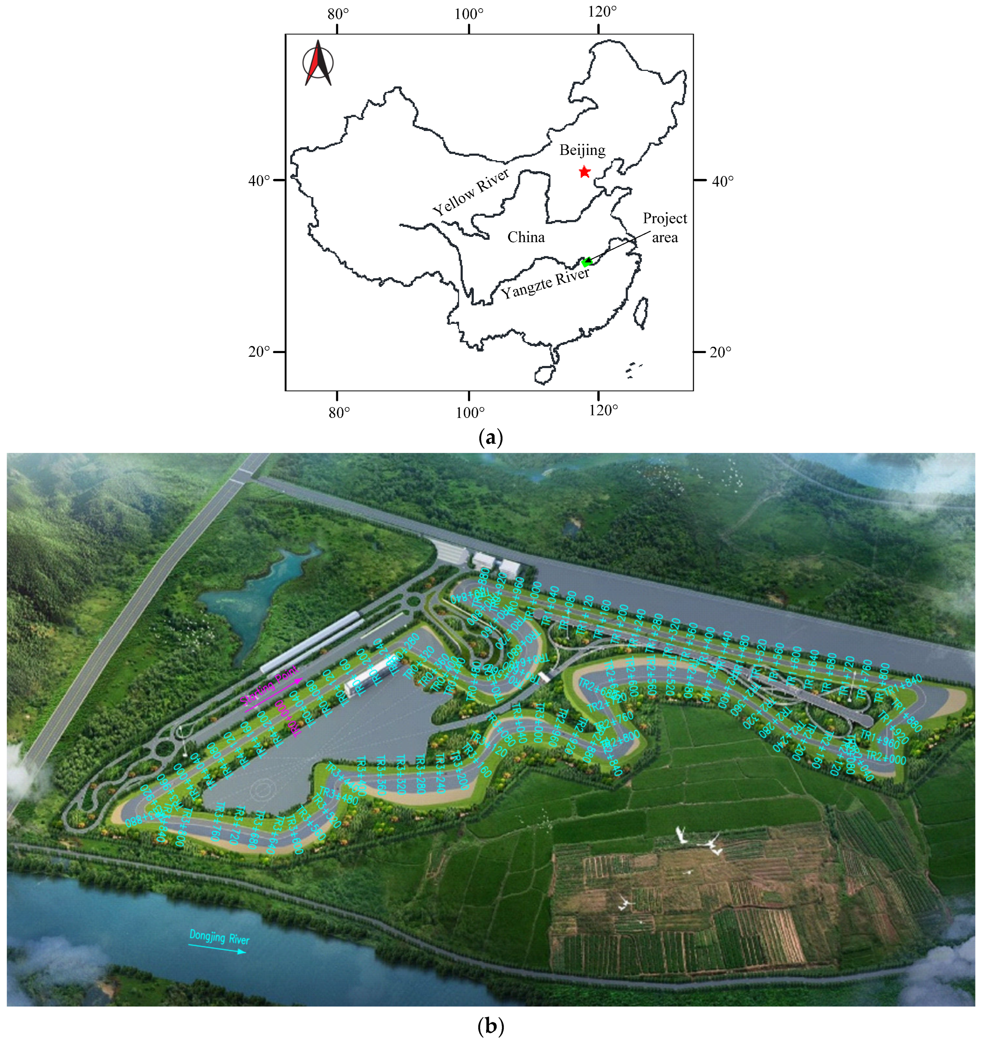
2.1. Project Introduction
2.2. Geological Conditions
2.3. Foundation Treatment Method
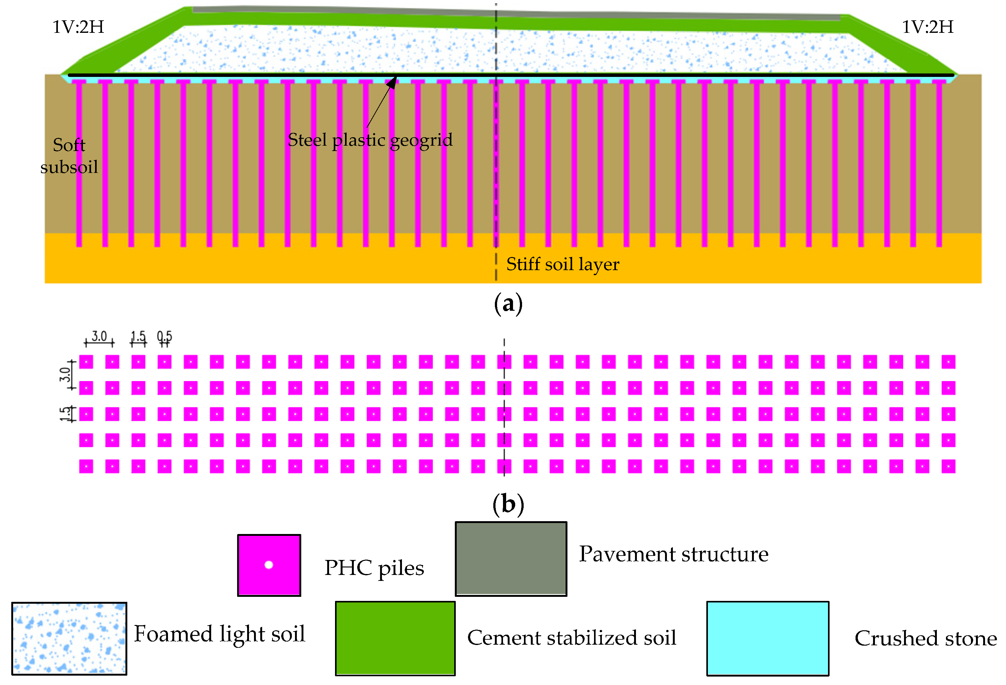
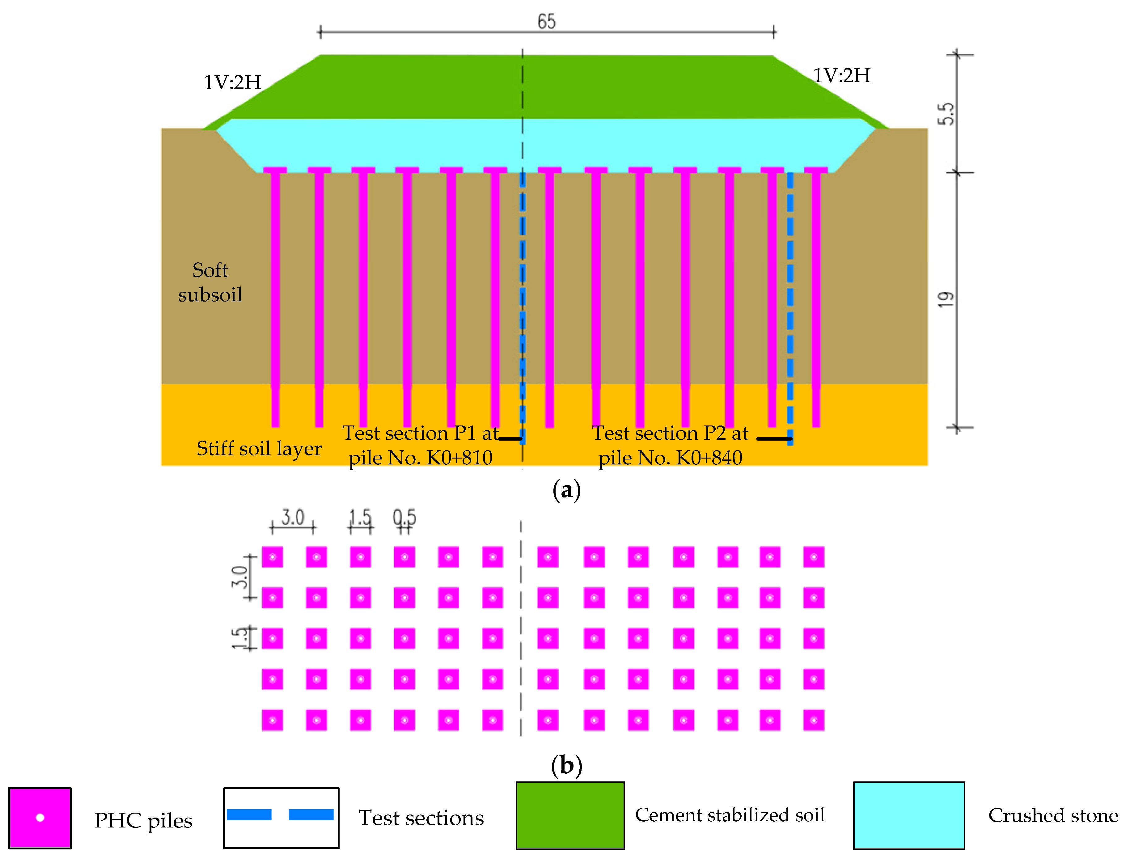
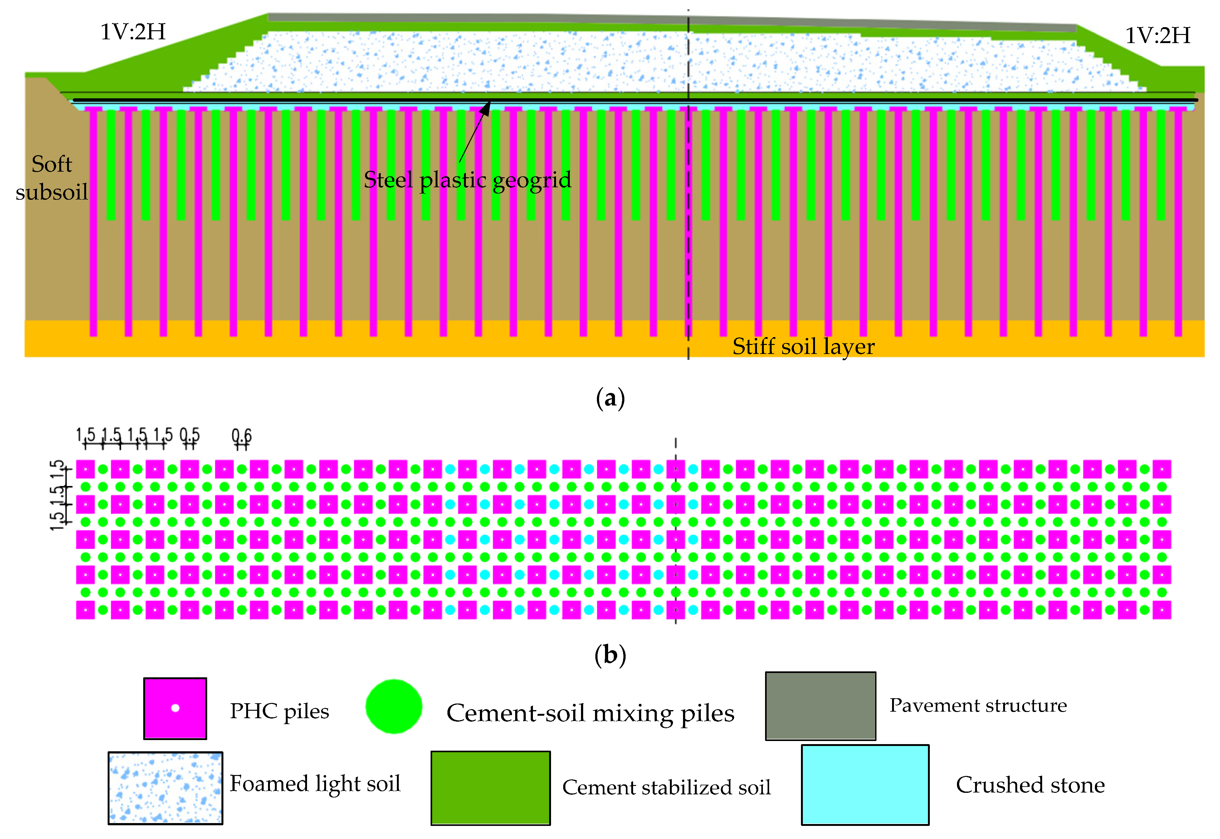
2.3.1. PHC Pile-Net Composite Foundation Treatment
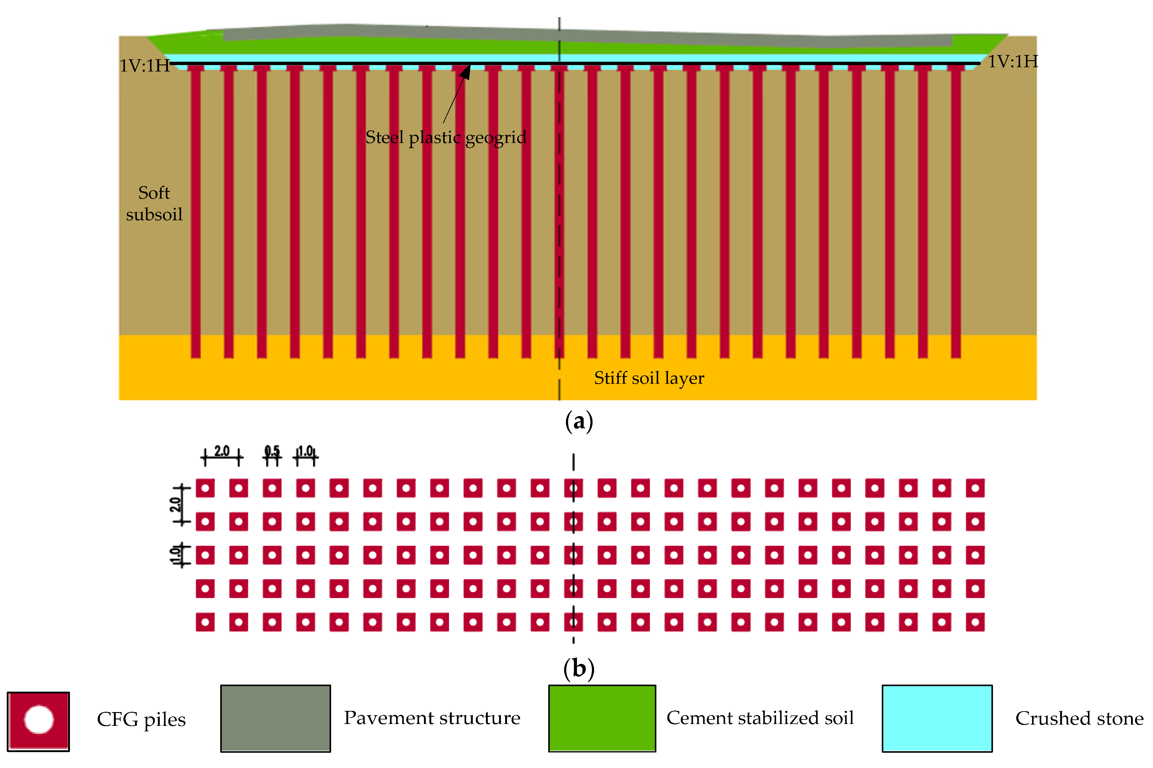
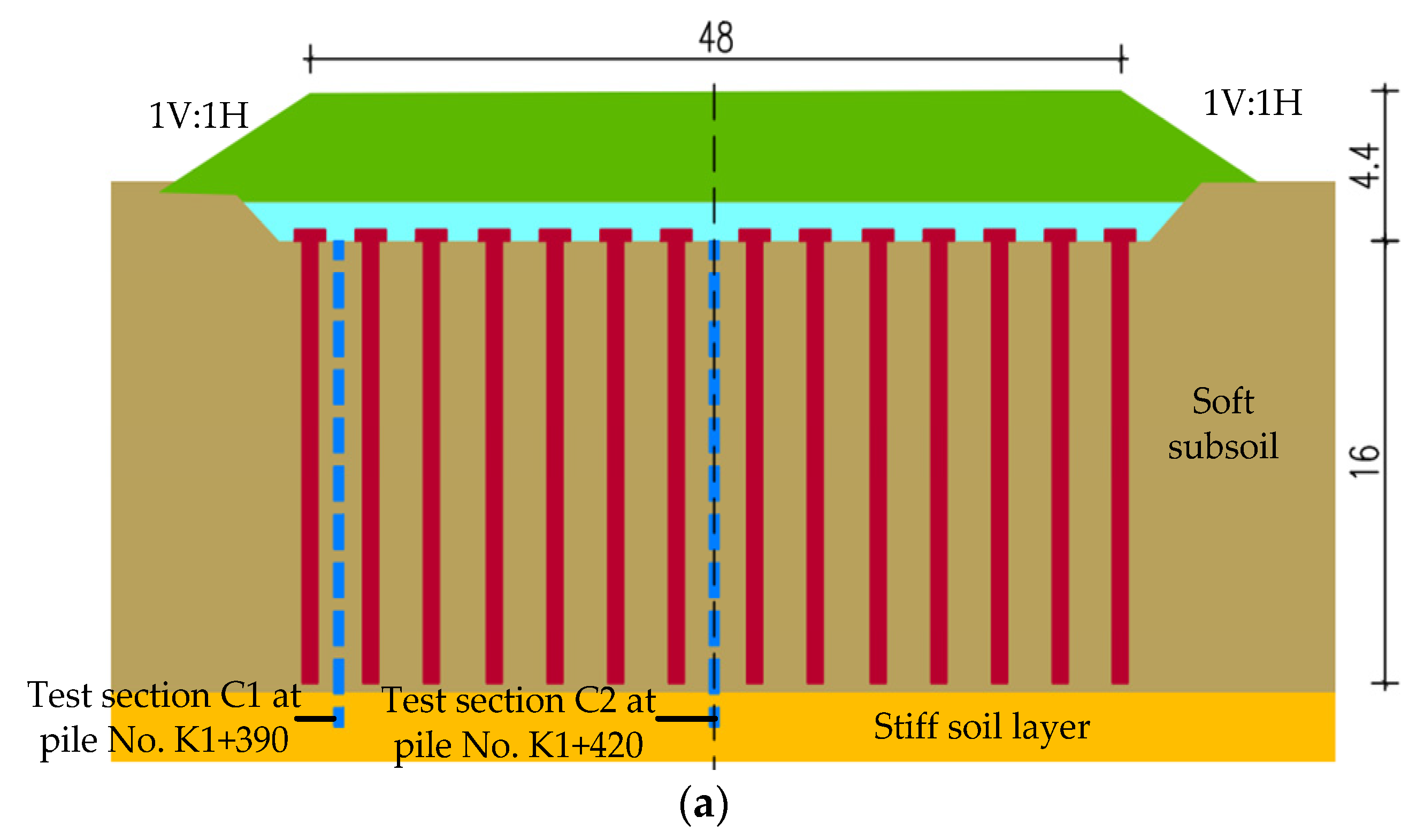
2.3.2. CFG Pile-Net Composite Foundation Treatment
3. Field Tests
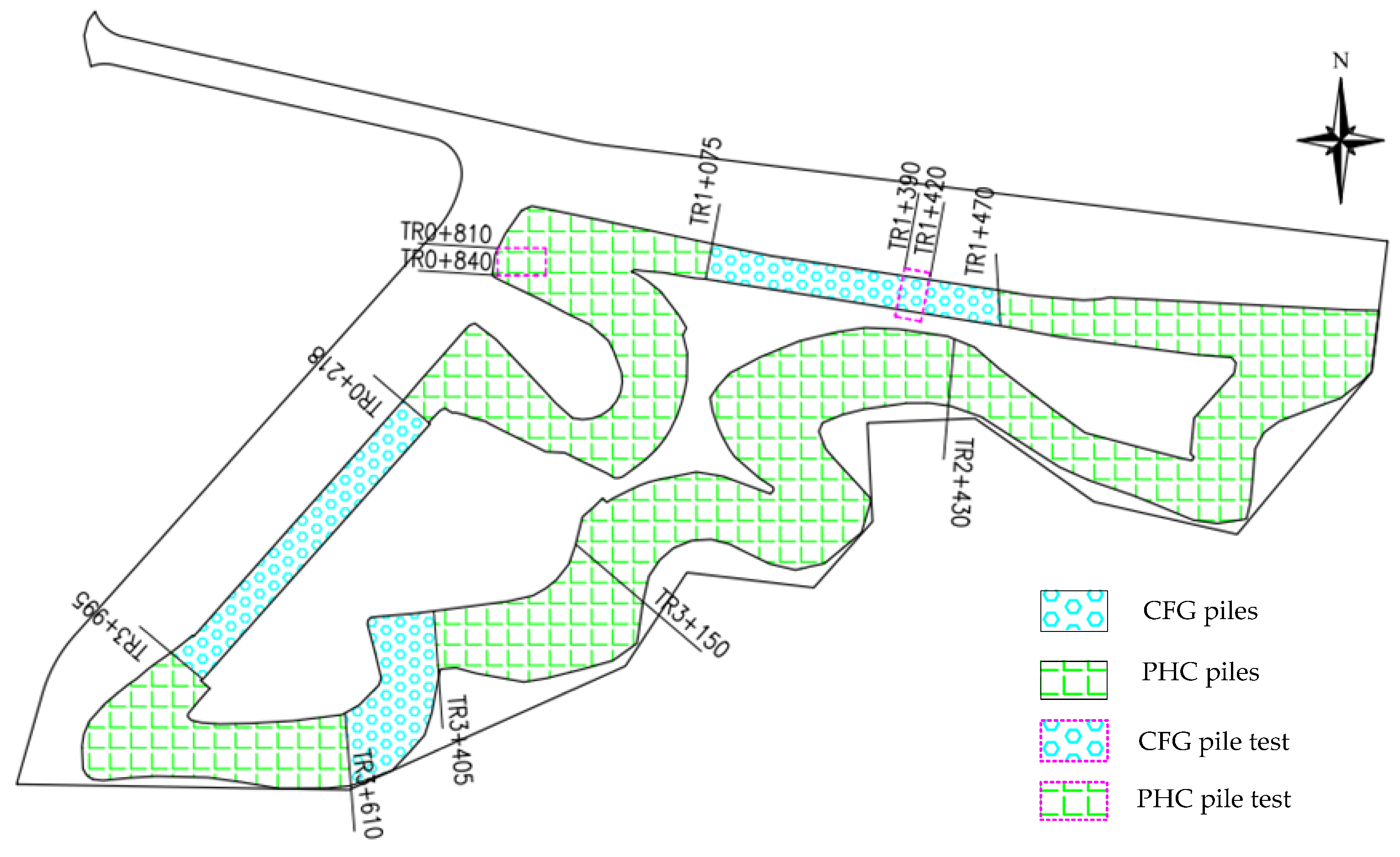
3.1. Test Sections
- (1)
- PHC test
- (2)
- CFG test
3.2. Layout of Monitoring Points
3.3. Test Scheme and Duration
3.4. Test Results and Analysis
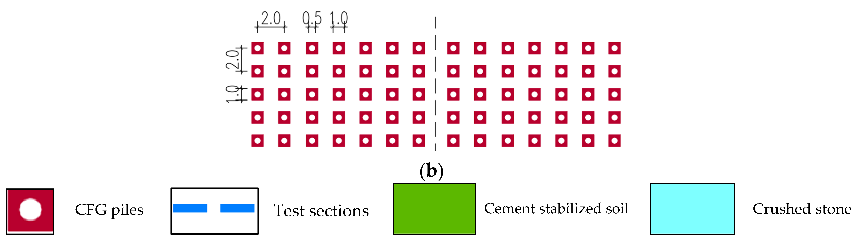
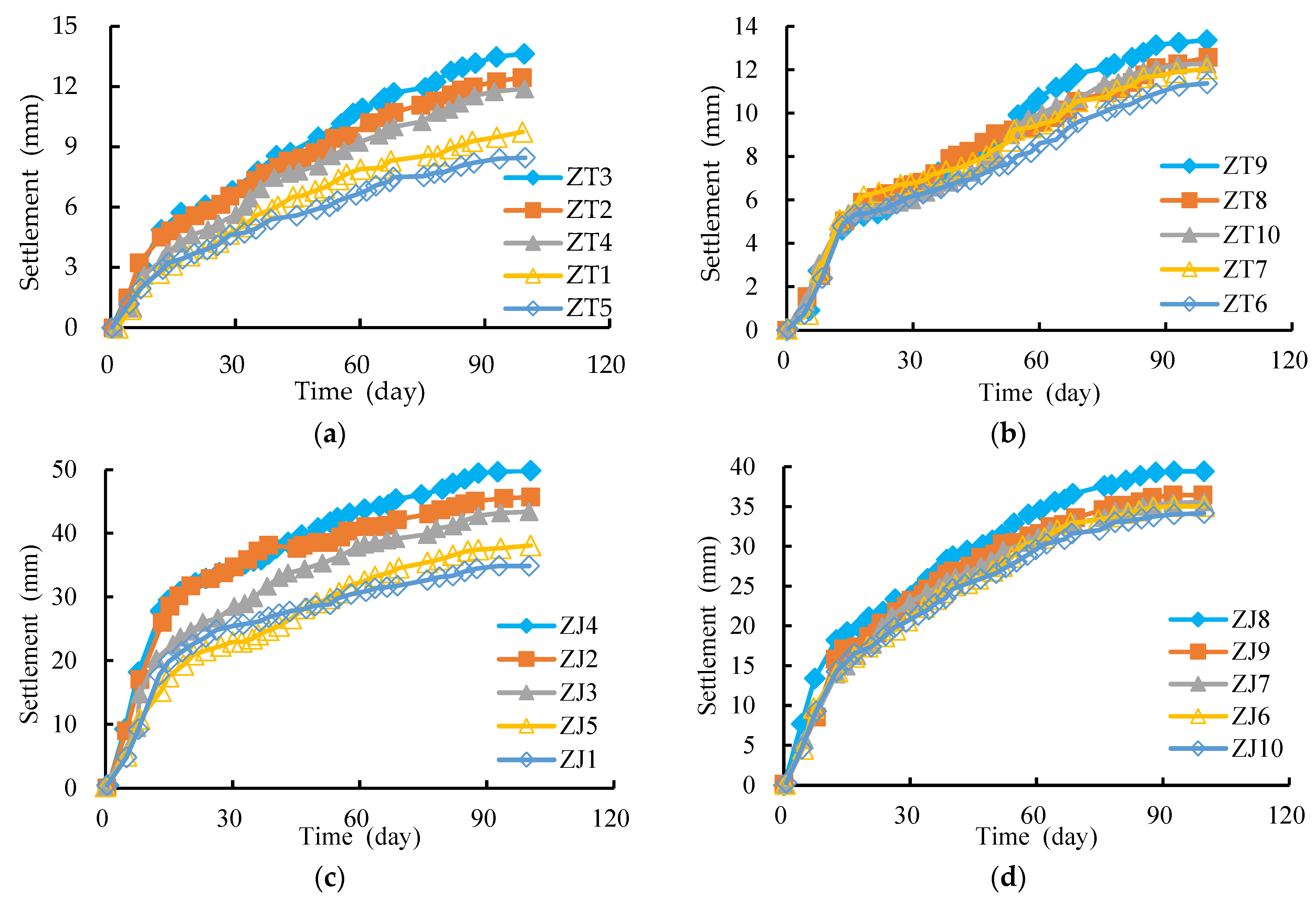
3.4.1. Settlement of the Pile Top and Soil between Piles
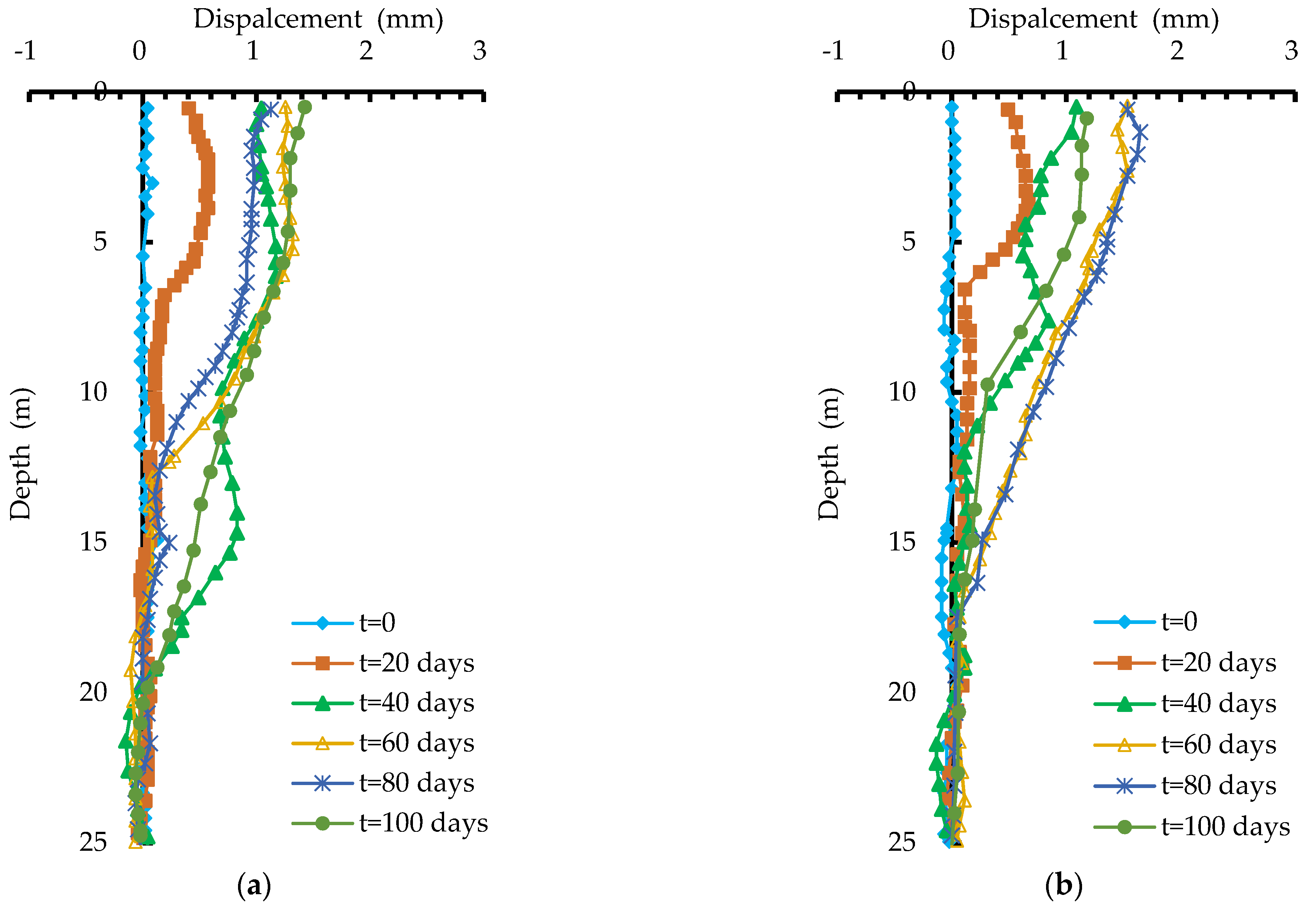
3.4.2. Deep Horizontal Displacement
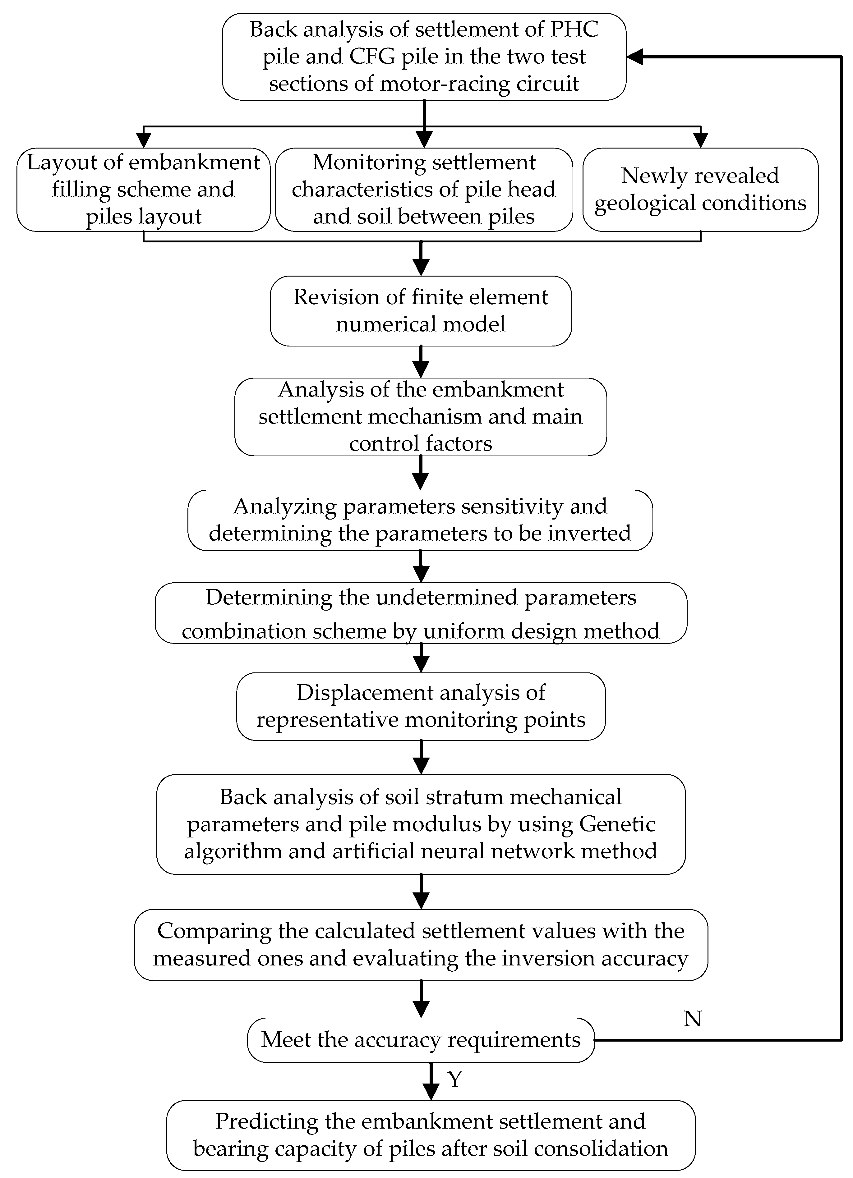
4. Back Analysis of Stratum Parameters and the Reinforcement Treatment of Embankments
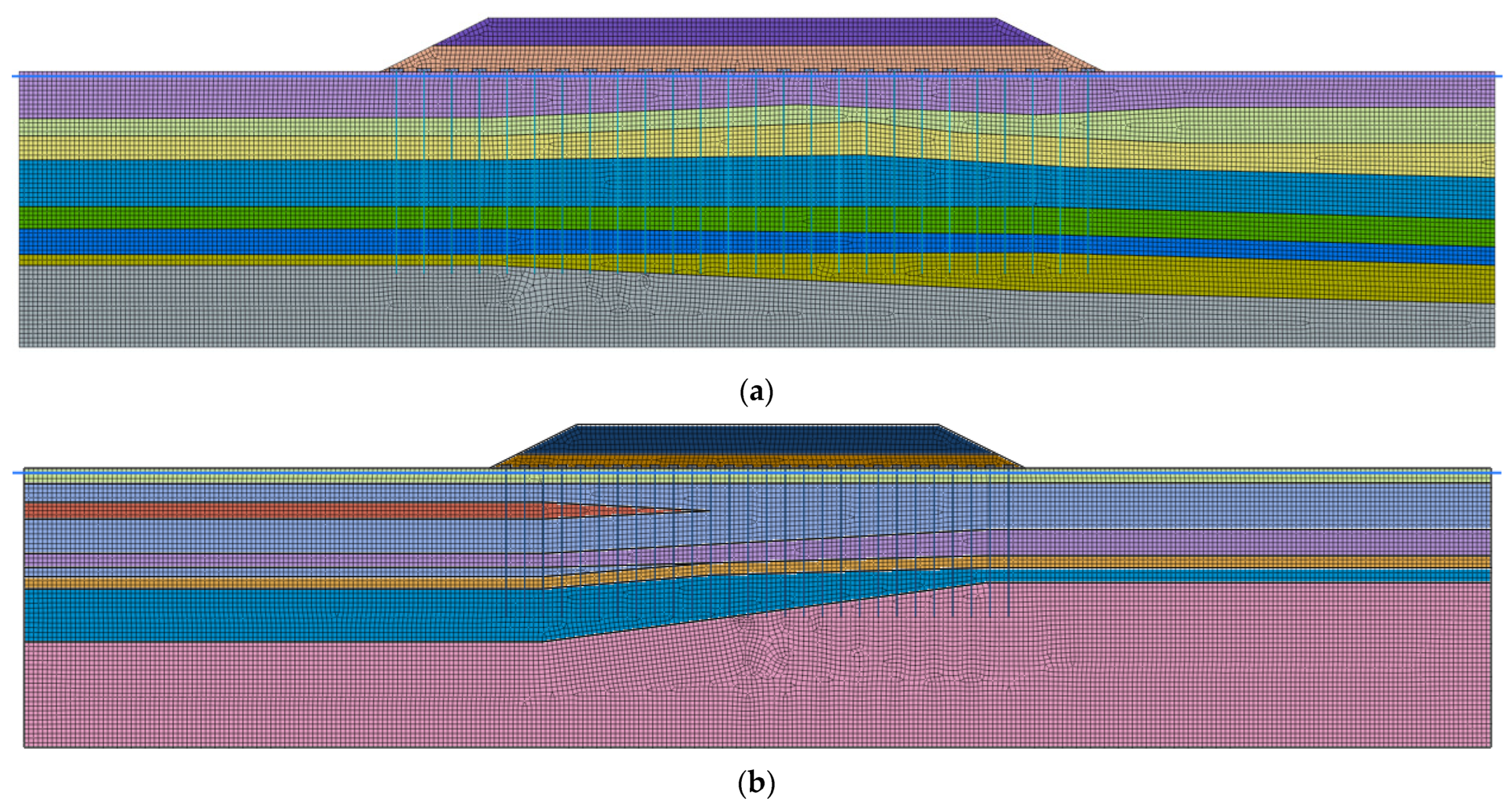
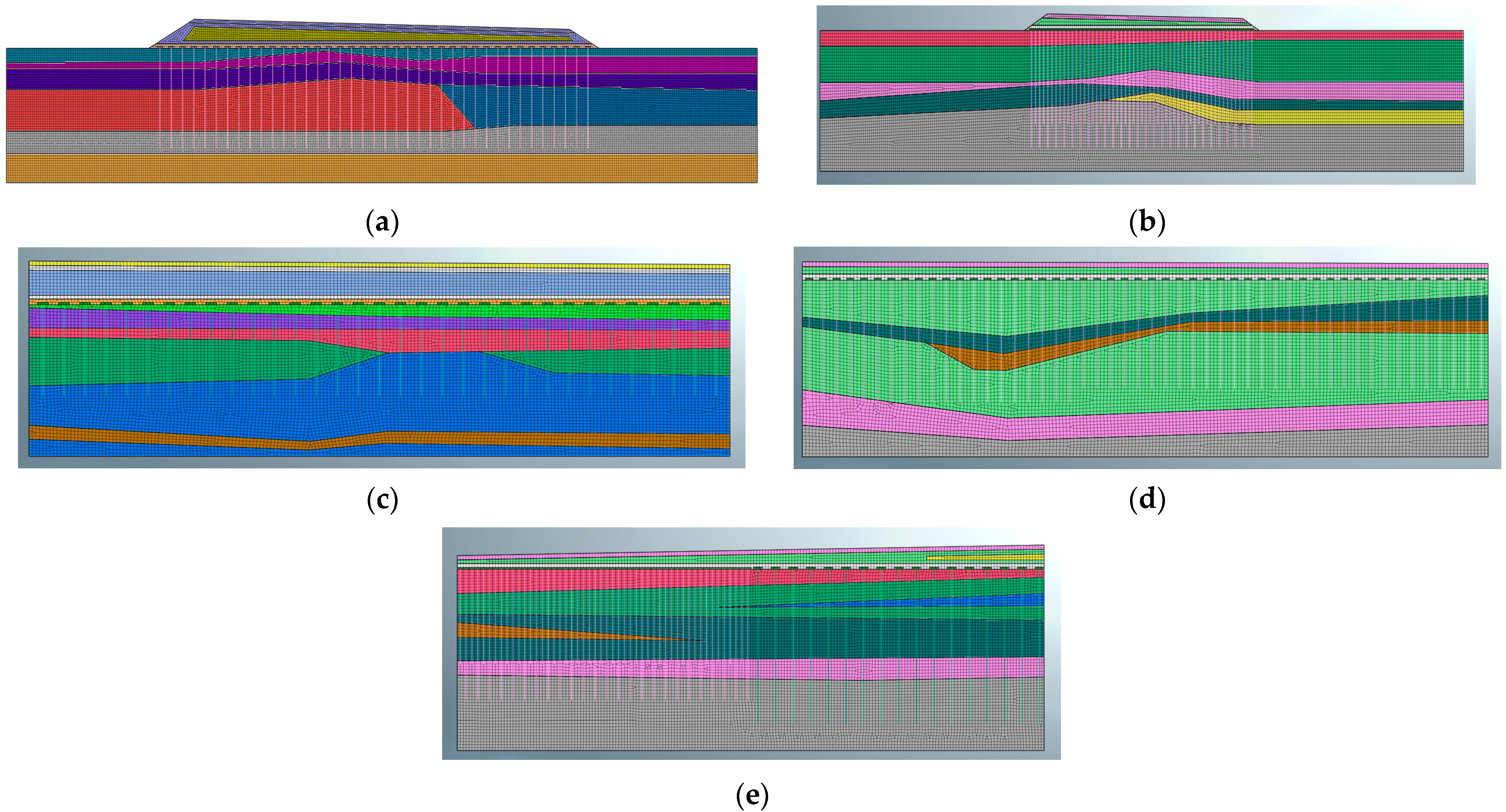
4.1. The Numerical Model and Mesh Grids
4.2. Constitutive Model and Computational Conditions
4.3. Back Analysis of Stratum Parameters
- (1)
- The selection of monitoring information on displacement. Prior to back analysis computation, proper monitoring information on displacement needs to be selected so as to obtain reasonable equivalent soil mechanical parameters and a pile modulus. In general, the selection should follow the following principles: (a) the monitoring information needs to be accurate and reliable without abnormal changes; (b) the monitoring information should be complete, information recorded by pre-buried monitoring equipment should be selected as a priority to carry out the back analysis of complete displacement; (c) the monitoring information needs to be adequate and representative; and (d) the monitoring information should change slightly and no invalid values should be used. Based on the above selection principles, the monitored data of soil settlement between piles at the two test sections (see Section 3.1) are selected. In this way, the monitoring points involved in the back analysis of the mechanical parameters of soil can be easily determined.
- (2)
- Determination of inversion parameters. Soil strata at the test sections mainly include 2-2 silty clay, 2a clay, 4 silty clay, and 6-1 silt, and the parameters of the pile modulus have a significant impact on the embankment settlement. Namely, six parameters highly sensitive to embankment settlement are subjected to back analysis, including the deformation moduli of 2-2 silty clay, 2a clay, 4 silty clay, and 6-1 silt, and the elastic modulus of PHC piles and CFG piles. Therefore, in total six parameters need to undergo back analysis.
- (3)
- The back analysis method. By optimizing the back propagation (BP) network structure through a genetic algorithm (GA), the GA-BP method can be formed [43]. This method has great advantages in its nonlinear mapping and global search ability, and has been widely applied in the back analysis of parameters. In order to obtain reasonable soil and pile parameters, the uniform design method and the GA-BP method are comprehensively used for parameters’ inversion. First, the scope of the parameters for back analysis were determined based on the results of field tests, laboratory experiments, and engineering experience. Then, the uniform design theory was used to design experiments through combinations of multiple parameters and levels, thus obtaining multiple groups of samples for orthogonal analysis. Afterwards, the above samples were imported into a neural network optimized by the genetic algorithm to perform network training and attain the nonlinear mapping relation between the parameters for back analysis and the monitored displacement. Finally, the measured values were input into the trained network to obtain the mechanical parameters for back analysis. According to calculation results from back analysis, the deformation moduli of 2-2 silty clay, 2a clay, 4 silty clay, and 6-1 silt within the disturbance range were 6.2 MPa, 13.2 MPa, 9.0 MPa, and 21.0 MPa. The elastic moduli of the PHC piles and CFG piles are 19.5 GPa and 12.0 GPa, respectively.
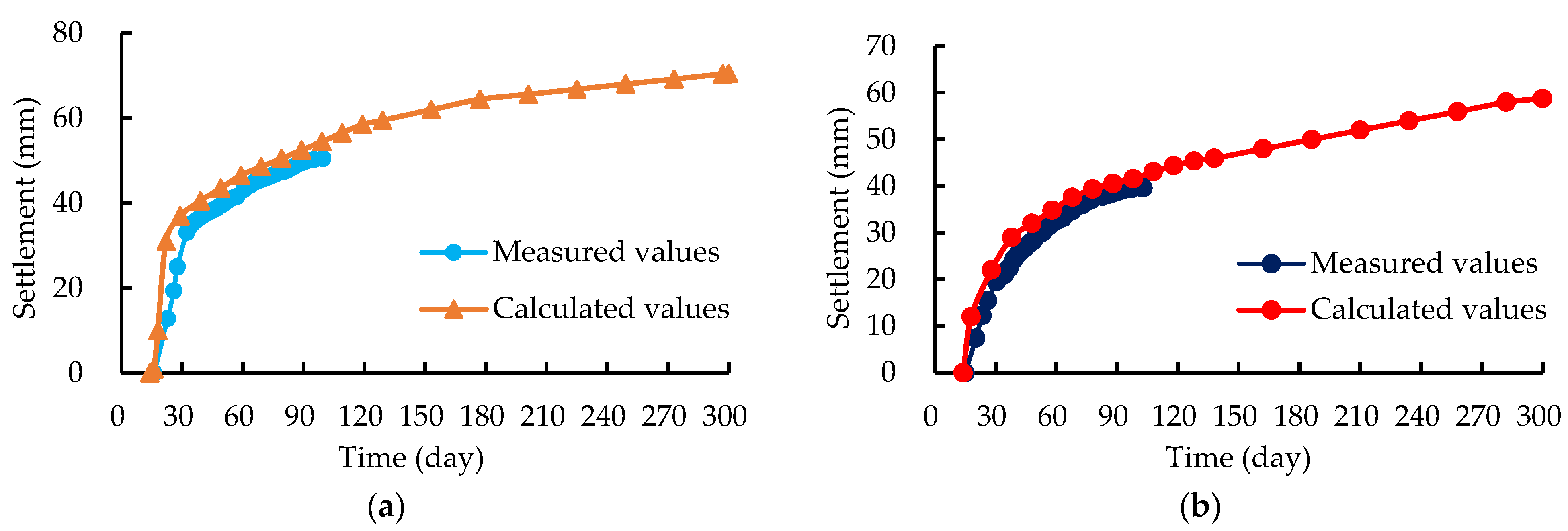
4.4. Evaluation of the Results Using the Back Analysis Method
4.5. Embankment Reinforcement Treatment and Its Effectiveness
4.5.1. Embankment Reinforcement Treatment
4.5.2. On Site Implementation Effect
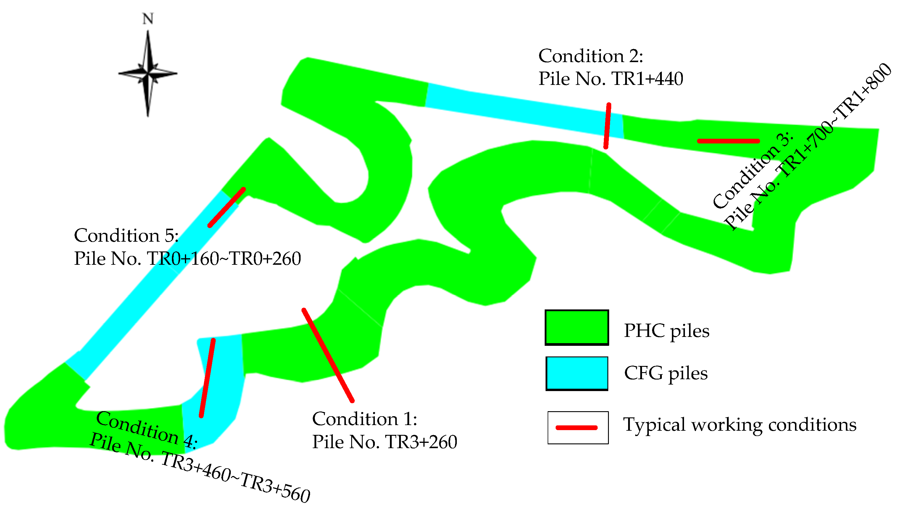
5. Numerical Simulation Analysis of the Typical Working Conditions of the Intelligent Connected Motor Racing Circuit
5.1. Model Construction and Mesh Grids
5.2. The Constitutive Model and Calculation Conditions
5.3. Analysis of Calculation Results
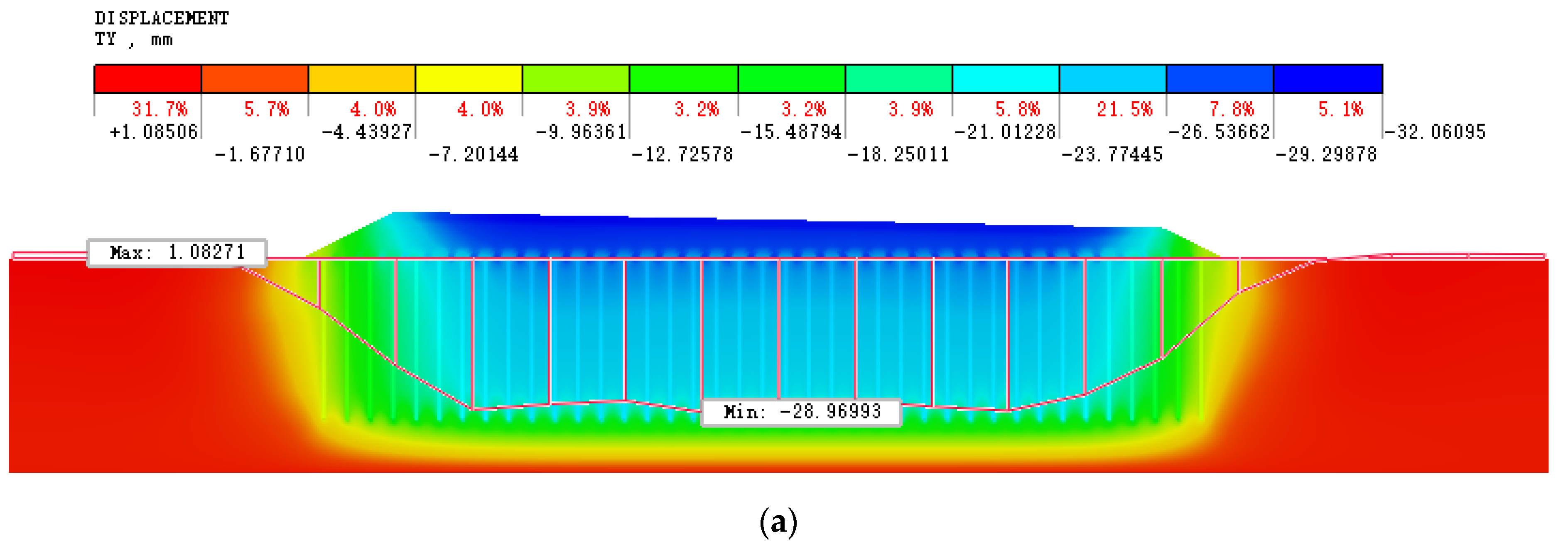
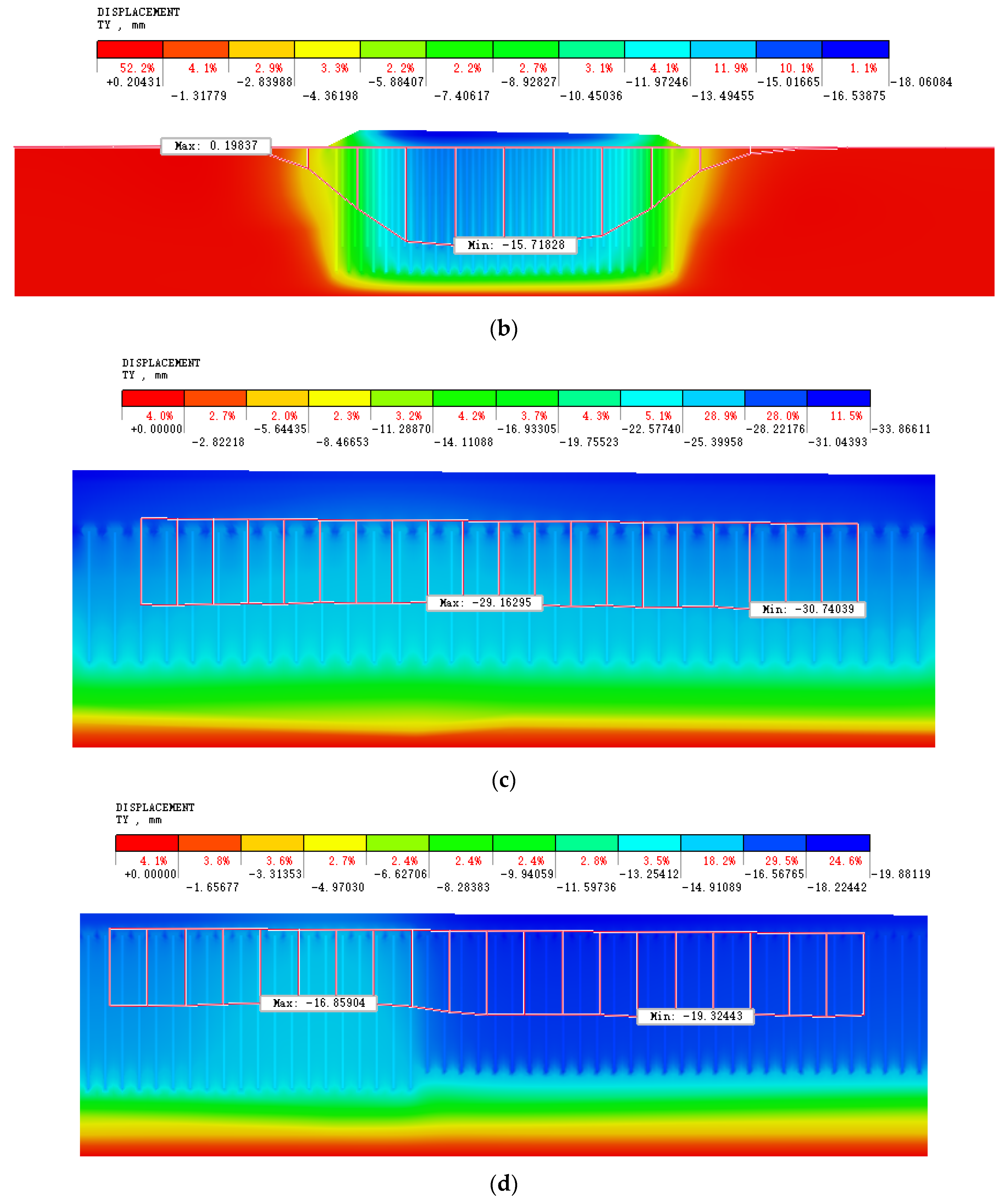
5.3.1. The Effect of the Pile-Net Composite Foundation on Settlement
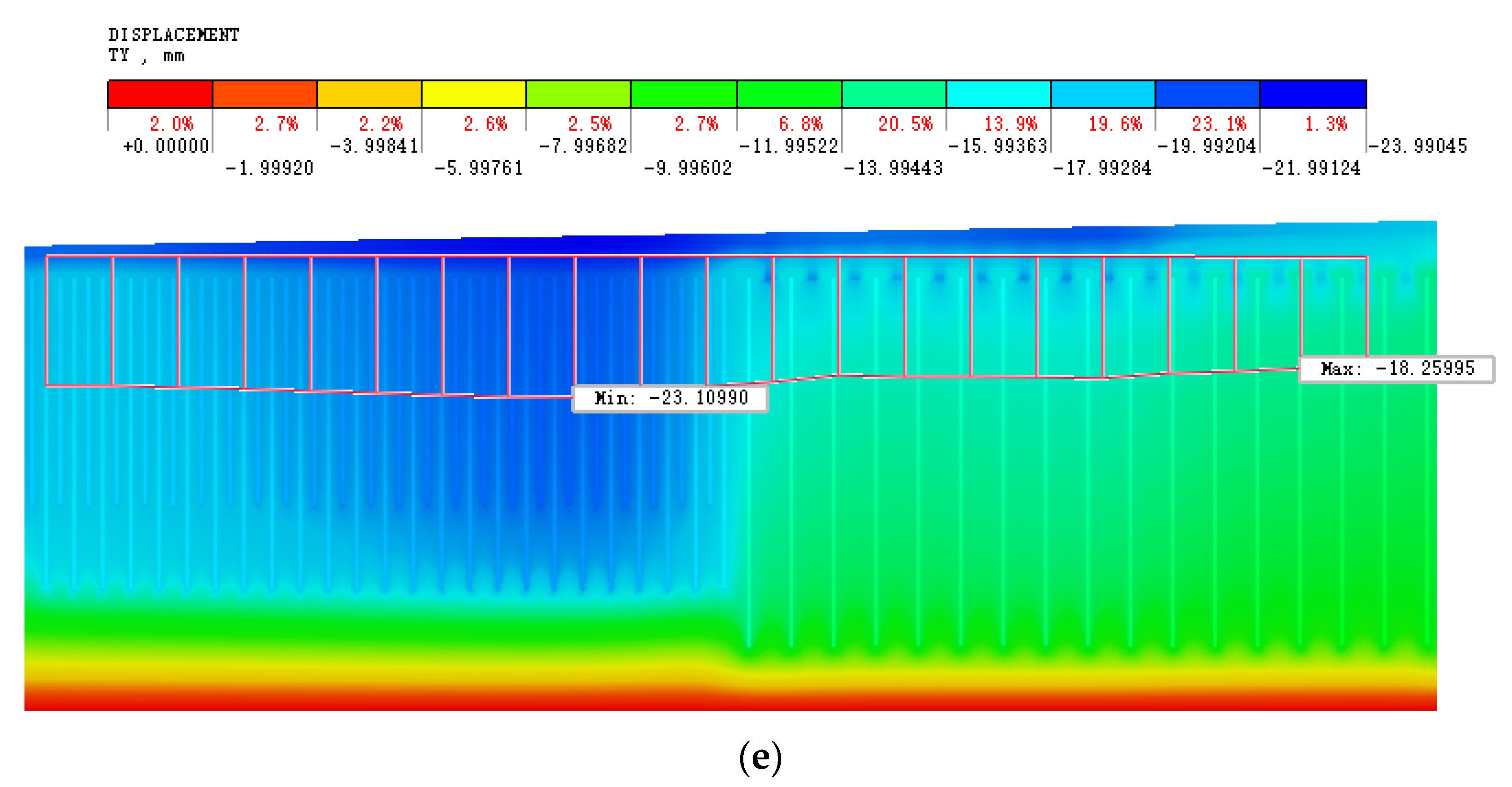
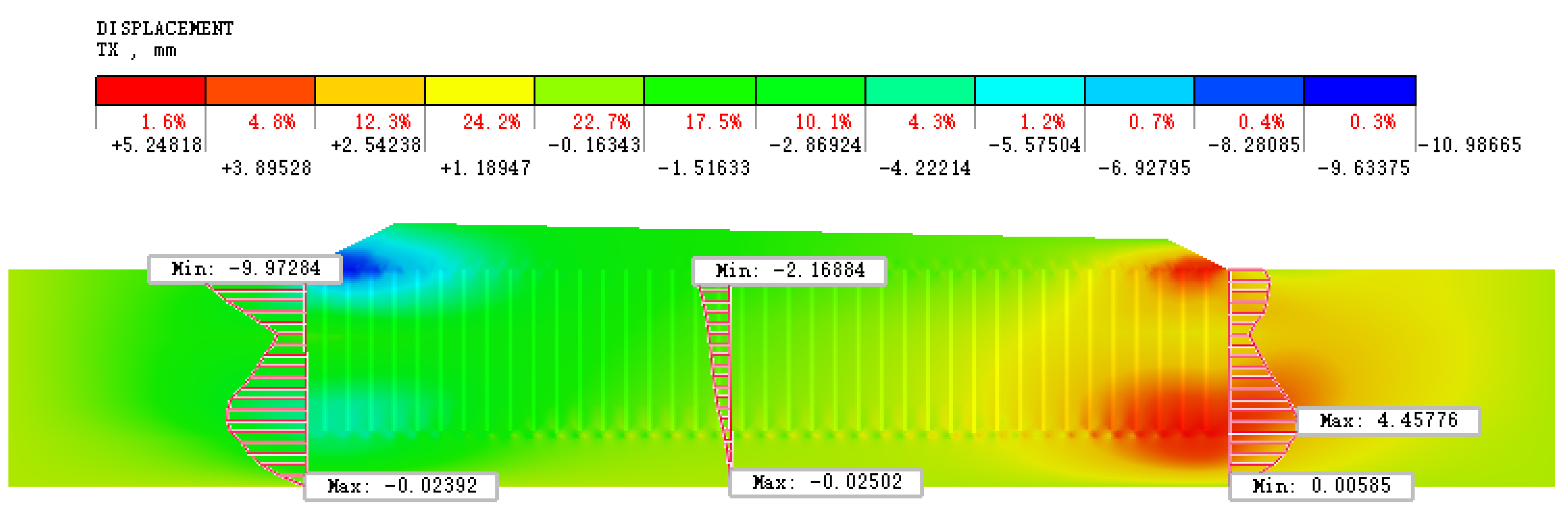
5.3.2. The Effect of the Pile-Net Composite Foundation on Lateral Deformation
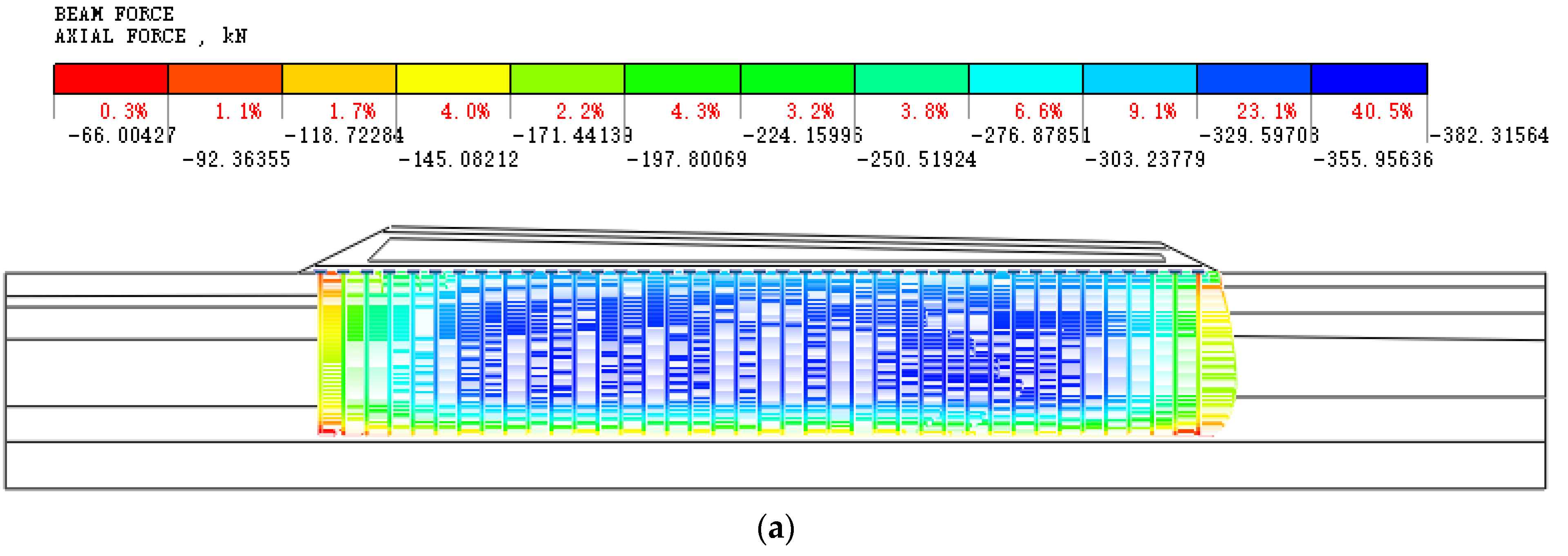
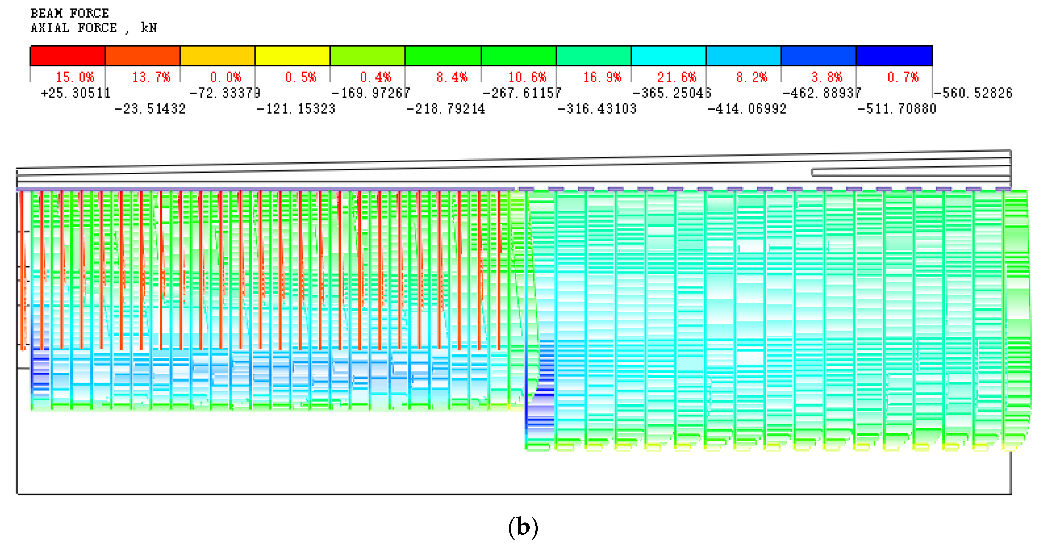
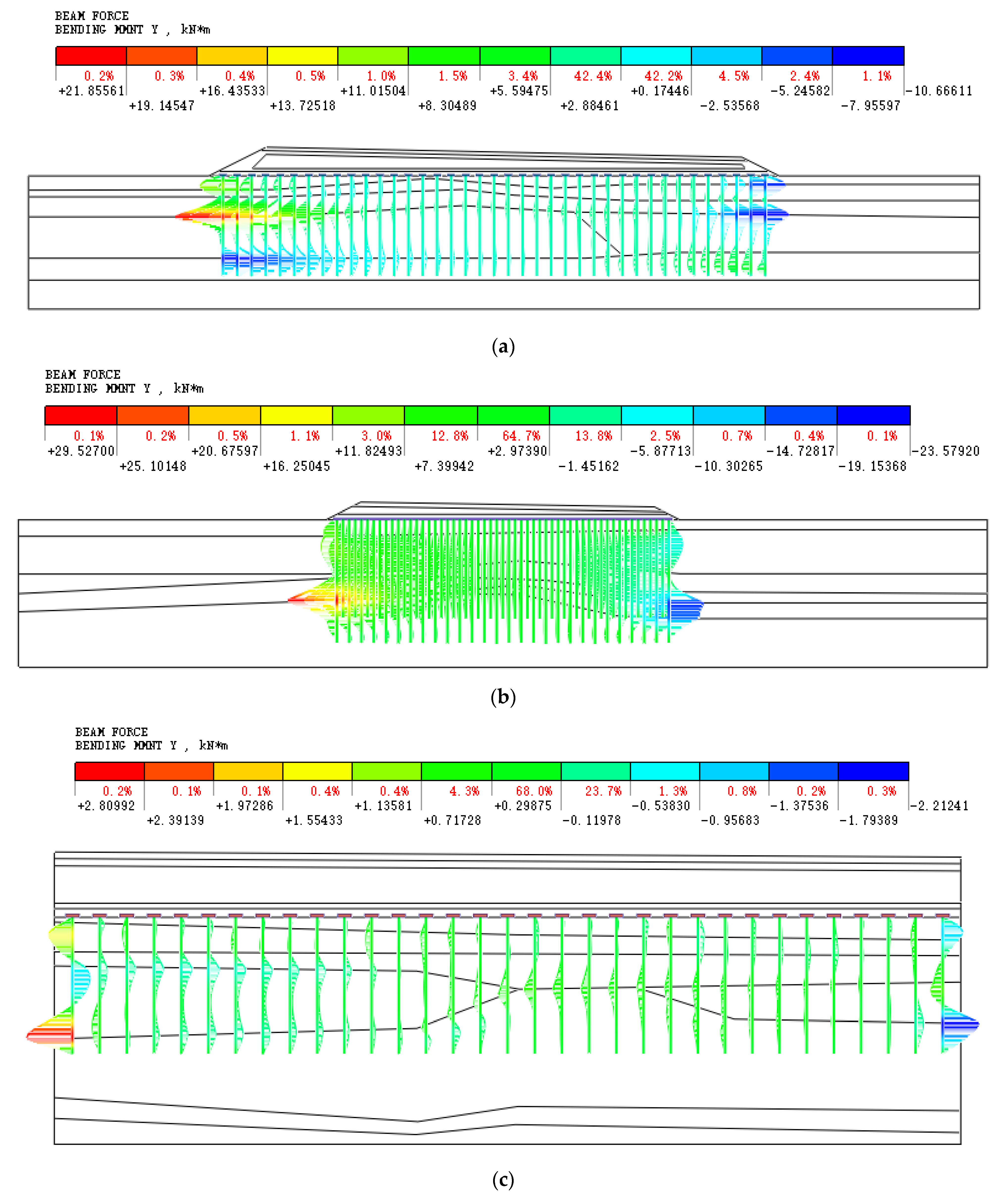
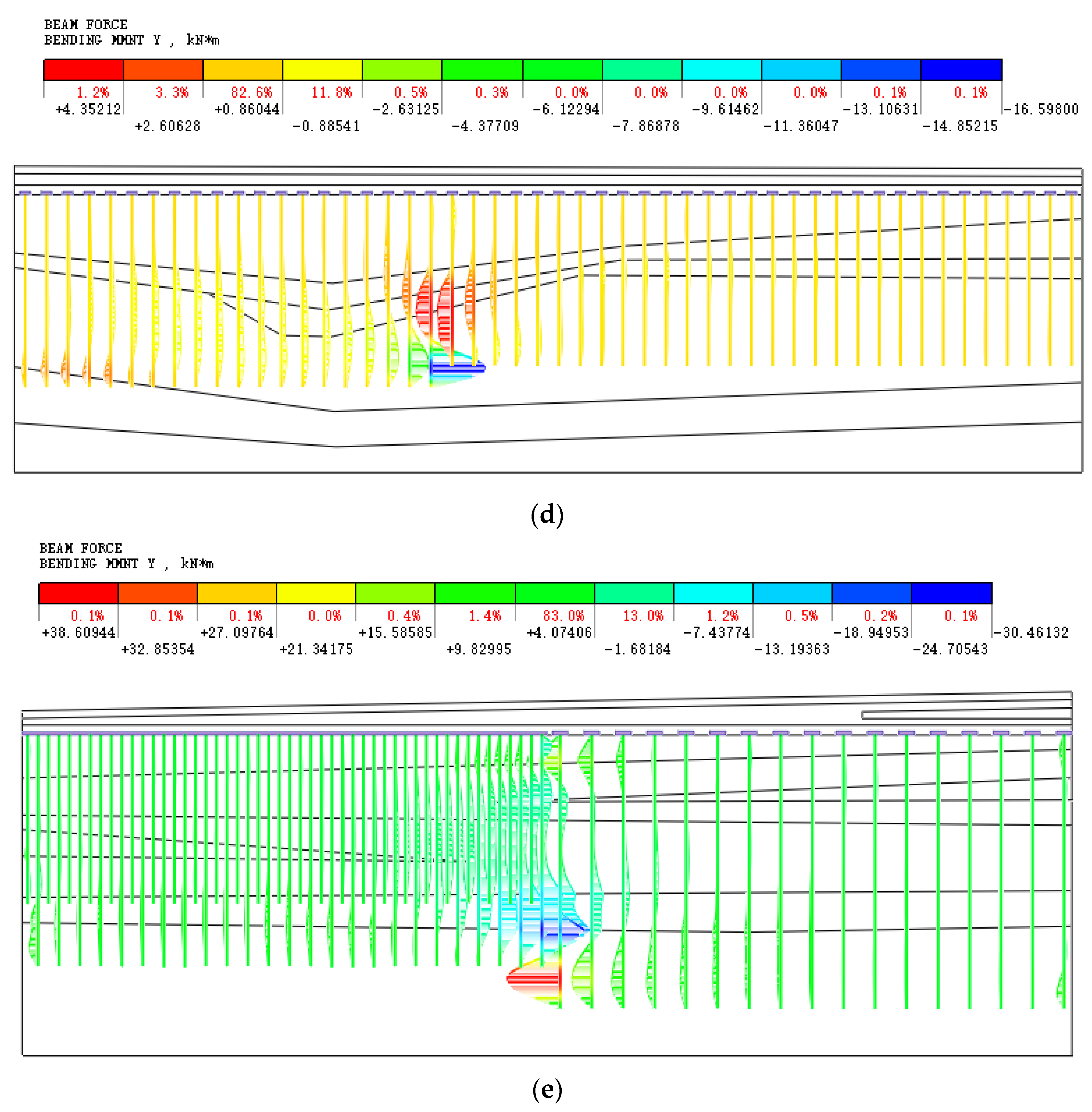
5.3.3. The Effect of the Pile-Net Composite Foundation on the Bearing Capacity of Piles
5.4. Comprehensive Evaluation of Settlement Control
6. Discussion
7. Conclusions
- (1)
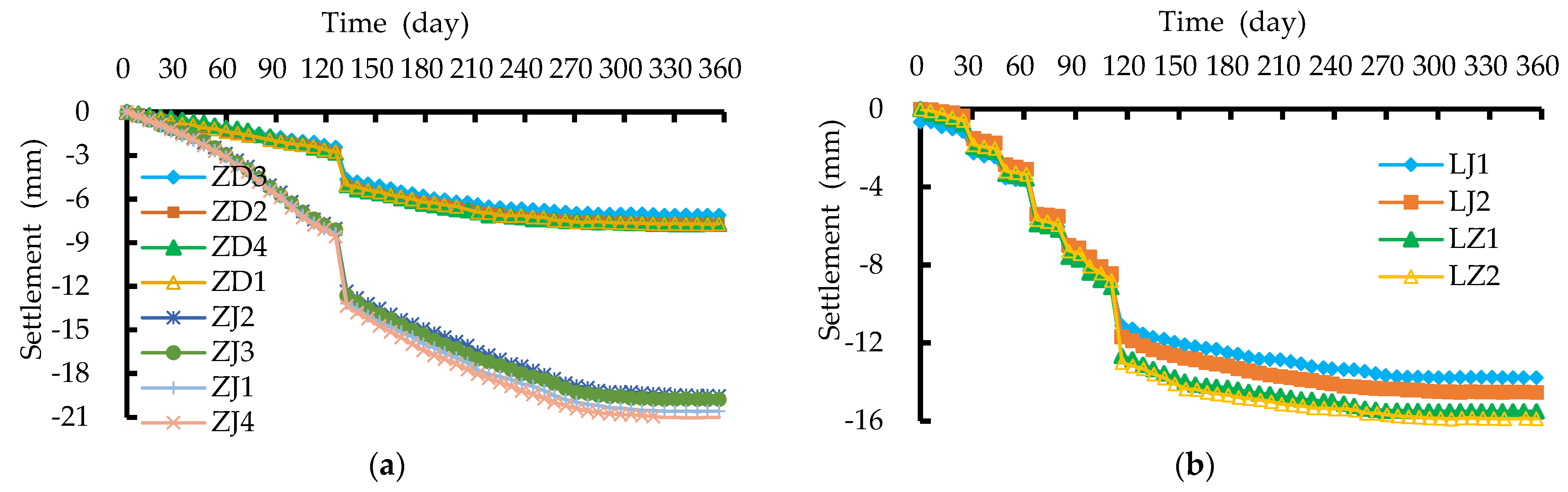
- Field tests showed that for medium or high filling areas, the maximum settlement of the pile head and soil between piles was 13.6 mm and 50.41 mm, respectively, and the settlement of soil between piles was 3.5~3.7 times that of adjacent pile heads. For low filling areas, the maximum settlement of the pile head and soil between piles was 13.34 mm and 39.65 mm, respectively. The cumulative settlement value of the pile head and soil between piles increased in a hyperbolic form. The lateral displacement direction of the soil strata in the loading area was spread outward from the loading center, and the lateral displacement did not exceed 1.5 mm.
- (2)
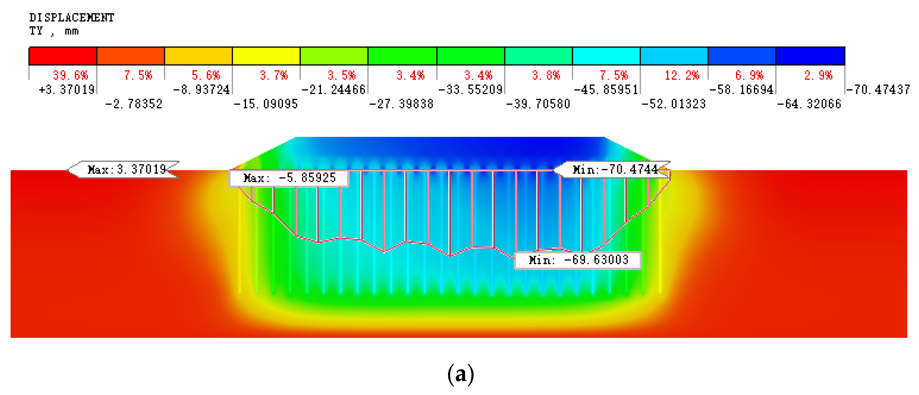
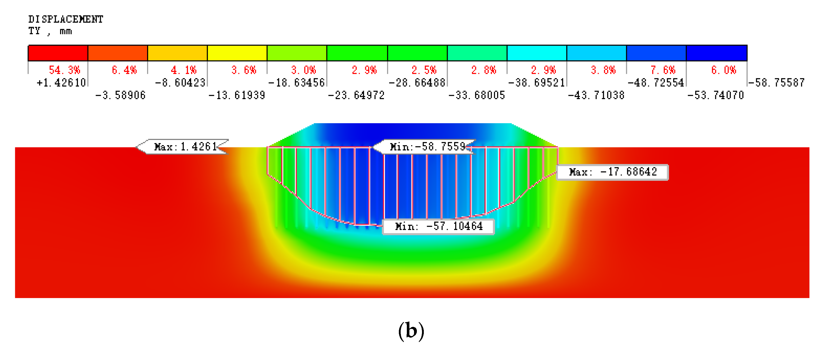
- Based on field test data, the GA-BP method, combining the uniform design method, was used to carry out back analysis on the mechanical parameters of the soil strata and pile modulus. The results showed that the settlement calculation values were basically consistent with the measured ones, with an error of no more than 10%, indicating good inversion accuracy. In addition, after soil consolidation, the predicted maximum settlement values of the PHC pile and CFG pile in the two pile test sections were about 70 mm and 59 mm, respectively. By adding PHC piles, CFG piles, and reinforcing cement–soil mixing piles between the piles, the maximum settlements were 21.01 mm and 15.88 mm, respectively, meeting the settlement control requirements.
- (3)
- By selecting five typical working conditions, a numerical analysis was conducted on the settlement and pile bearing capacity of the embankment in the engineering area. The calculation showed that after the soil consolidation was completed, the maximum settlement of the embankment was 27.0 mm, and the maximum LUSR of the embankment was 1.3/4000. The maximum lateral displacement in the middle of the embankment is about 2.2 mm. The maximum axial forces of the PHC piles and CFG piles were 382.3 kN and 560 kN, respectively, and the maximum bending moments were 21.8 kN·m and 38.6 kN·m. The axial forces and bending moments of the piles were within their compressive and flexural strength ranges. It can be concluded that the pile-net composite foundation treatment methods adopted in this project were feasible, and the embankment settlement and differential settlement were controllable, which can meet safety and operational requirements.
Author Contributions
Funding
Data Availability Statement
Conflicts of Interest
References
- Yin, J.H.; Feng, W.Q. A new simplified method and its verification for calculation of consolidation settlement of a clayey soil with creep. Can. Geotech. J. 2017, 54, 333–347. [Google Scholar] [CrossRef]
- Zhu, H.H.; Zhang, C.C.; Mei, G.X.; Shi, B.; Gao, L. Prediction of one-dimensional compression behavior of Nansha clay using fractional derivatives. Mar. Georesources Geotechnol. 2017, 35, 688–697. [Google Scholar] [CrossRef]
- Zhang, S.M.; Jian, G.L.; Liao, Y.L. Effect of the strengthening area and the slope rate on bearing and deforming behaviors of CFG pile-geogrid composite foundations. Chin. J. Rock Mech. Eng. 2019, 38, 192–202. [Google Scholar]
- Zheng, G.; Zhao, J.P.; Zhou, H.Z. State-of-the-art review for techniques on ground improvement of highway and railway. Chin. J. Ground Improv. 2021, 3, 91–99. (In Chinese) [Google Scholar]
- Wu, P.C.; Yin, J.H.; Feng, W.Q.; Chen, W.B. Experimental study on geosynthetic-reinforced sand fill over marine clay with or without deep cement mixed soil columns under different loadings. Undergr. Space 2019, 4, 340–347. [Google Scholar] [CrossRef]
- Reshma, B.; Rajagopal, K.; Viswanadham, B.V.S. Centrifuge model studies on the settlement response of geosynthetic piled embankments. Geosynth. Int. 2020, 27, 170–181. [Google Scholar] [CrossRef]
- Wu, P.C.; Feng, W.Q.; Yin, J.H. Numerical study of creep effects on settlements and load transfer mechanisms of soft soil improved by deep cement mixed soil columns under embankment load. Geotext. Geomembr. 2020, 48, 331–348. [Google Scholar] [CrossRef]
- Esen, A.F.; Woodward, P.K.; Laghrouche, O.; Čebašek, T.M.; Brennan, A.J.; Robinson, S.; Connolly, D.P. Full-scale laboratory testing of a geosynthetically reinforced soil railway structure. Transp. Geotech. 2021, 28, 100526. [Google Scholar] [CrossRef]
- Arulrajah, A.; Abdullah, A.; Bo, M.W.; Bouazza, A. Ground improvement techniques for railway embankments. Proc. Inst. Civ. Eng. Ground Improv. 2009, 162, 3–14. [Google Scholar] [CrossRef]
- Terzaghi, K. Theoretical Soil Mechanics; Wiley: New York, NY, USA, 1943. [Google Scholar]
- Low, B.K.; Tang, S.K.; Choa, V. Arching in piled embankments. J. Geotech. Eng. 1994, 120, 1917–1938. [Google Scholar] [CrossRef]
- Giroud, J.P.; Bonaparte, R.; Beech, J.F.; Gross, B.A. Design of soil layer-geosynthetic systems overlying voids. Geotext. Geomembr. 1990, 9, 11–50. [Google Scholar] [CrossRef]
- Hewlett, W.J.; Randolph, M.F. Analysis of piled embankments. Ground Eng. 1988, 21, 12–18. [Google Scholar]
- Chen, Y.M.; Cao, W.P.; Chen, R.P. An experimental investigation of soil arching within basal reinforced and unreinforced piled embankments. Geotext. Geomembr. 2008, 26, 164–174. [Google Scholar]
- Castro, J.; Sagaseta, C. Consolidation and deformation around stone columns: Numerical evaluation of analytical solutions. Comput. Geotech. 2011, 38, 354–362. [Google Scholar] [CrossRef]
- Liu, F.; Zhang, J.J. Centrifuge test on deformation characteristics of pile-geogrid composite foundation in soft soil under slope. Chin. J. Rock Mech. Eng. 2018, 37, 209–219. [Google Scholar]
- Blanc, M.; Rault, G.; Thorel, L.; Almeida, M. Centrifuge investigation of load transfer mechanisms in a granular mattress above a rigid inclusions network. Geotext. Geomembr. 2013, 36, 92–105. [Google Scholar] [CrossRef]
- Fagundes, D.F.; Almeida, M.S.; Thorel, L.; Blanc, M. Load transfer mechanism and deformation of reinforced piled embankments. Geotext. Geomembr. 2017, 45, 1–10. [Google Scholar] [CrossRef]
- Girout, R.; Blanc, M.; Thorel, L.; Dias, D. Geosynthetic reinforcement of pile-supported embankments. Geosynth. Int. 2018, 25, 37–49. [Google Scholar] [CrossRef]
- Das, A.K.; Deb, K. Experimental and 3D numerical study on time-dependent behavior of stone column–supported embankments. Int. J. Geomech. 2018, 18, 04018011. [Google Scholar] [CrossRef]
- Liu, J.W.L.; Zhang, Z.M.; Zhao, Y.B.; Lin, C.G. Statistical research on performance of prestressed concrete pipe piles. In Proceedings of the 2011 International Conference on Electric Technology and Civil Engineering (ICETCE), Lushan, China, 22–24 April 2011; pp. 711–714. [Google Scholar]
- Oh, Y.I.; Shin, E. C Reinforcement and arching effect of geogrid-reinforced and pile-supported embankment on marine soft ground. Mar. Georesources Geotechnol. 2007, 25, 97–118. [Google Scholar] [CrossRef]
- Zhang, C.; Jiang, G.; Liu, X.; Buzzi, O. Arching in geogrid-reinforced pile-supported embankments over silty clay of medium compressibility: Field data and analytical solution. Comput. Geotech. 2016, 77, 11–25. [Google Scholar] [CrossRef]
- Yang, M.; Liu, S. Field tests and finite element modeling of a prestressed concrete pipe pile-composite foundation. KSCE J. Civ. Eng. 2015, 19, 2067–2074. [Google Scholar] [CrossRef]
- Zhang, S.; Tang, C. Subgrade Settlement of High Speed Railway in Seasonal Frozen Soil Area. J. Northeast. Univ. (Nat. Sci.) 2013, 34, 1202–1205. [Google Scholar]
- Zhang, F.; Liu, Y.; Xu, Z.Y.; Li, Z.Y. Factors influencing subgrade post-construction settlement of CFG pile composite foundation in Wuhan-Guangzhou high-speed railway. J. Southwest Jiaotong Univ. 2015, 50, 783–788. [Google Scholar]
- Yoo, C. Settlement behavior of embankment on geosynthetic-encased stone column installed soft ground—A numerical investigation. Geotext. Geomembr. 2015, 43, 484–492. [Google Scholar] [CrossRef]
- Zhao, L.S.; Zhou, W.H.; Fatahi, B.; Li, X.B.; Yuen, K.V. A dual beam model for geosynthetic-reinforced granular fill on an elastic foundation. Appl. Math. Model. 2016, 40, 9254–9268. [Google Scholar] [CrossRef]
- Jamsawang, P.; Yoobanpot, N.; Thanasisathit, N.; Voottipruex, P.; Jongpradist, P. Three-dimensional numerical analysis of a DCM column-supported highway embankment. Comput. Geotech. 2016, 72, 42–56. [Google Scholar] [CrossRef]
- Nunez, M.A.; Briançon, L.; Dias, D. Analyses of a pile-supported embankment over soft clay: Full-scale experiment, analytical and numerical approaches. Eng. Geol. 2013, 153, 53–67. [Google Scholar] [CrossRef]
- Hájek, V.; Mašín, D.; Boháč, J. Capability of constitutive models to simulate soils with different OCR using a single set of parameters. Comput. Geotech. 2009, 36, 655–664. [Google Scholar] [CrossRef]
- Yan, W.M.; Li, X.S. Mechanical response of a medium-fine-grained decomposed granite in Hong Kong. Eng. Geol. 2012, 129, 1–8. [Google Scholar] [CrossRef]
- Abad, S.A.N.K.; Tugrul, A.; Gokceoglu, C.; Armaghani, D.J. Characteristics of weathering zones of granitic rocks in Malaysia for geotechnical engineering design. Eng. Geol. 2016, 200, 94–103. [Google Scholar] [CrossRef]
- Deb, K. A mathematical model to study the soil arching effect in stone column-supported embankment resting on soft foundation soil. Appl. Math. Model. 2010, 34, 3871–3883. [Google Scholar] [CrossRef]
- Zhuang, Y.; Wang, K. Finite element analysis on the dynamic behavior of soil arching effect in piled embankment. Transp. Geotech. 2018, 14, 8–21. [Google Scholar] [CrossRef]
- Zhao, L.S.; Zhou, W.H.; Geng, X.; Yuen, K.V.; Fatahi, B. A closed-form solution for column-supported embankments with geosynthetic reinforcement. Geotext. Geomembr. 2019, 47, 389–401. [Google Scholar] [CrossRef]
- Chen, R.P.; Zhou, W.H.; Chen, Y.M. Influences of soil consolidation and pile load on the development of negative skin friction of a pile. Comput. Geotech. 2009, 36, 1265–1271. [Google Scholar] [CrossRef]
- Yu, J.; Cai, Y.; Qi, Z.; Guan, Y.; Liu, S.; Tu, B. Analytical analysis and field test investigation of consolidation for CCSG pile composite foundation in soft clay. J. Appl. Math. 2013, 2013, 795962. [Google Scholar] [CrossRef]
- Filz, G.M.; Sloan, J.A.; McGuire, M.P.; Smith, M.; Collin, J. Settlement and vertical load transfer in column-supported embankments. J. Geotech. Geoenvironmental Eng. 2019, 145, 04019083. [Google Scholar] [CrossRef]
- Luo, Q.; Lu, Q.Y. Settlement calculation of rigid pile composite foundation considering pile-soil relative slip under embankment load. China J. Highw. Transp. 2018, 31, 20–30. (In Chinese) [Google Scholar]
- Institute of Rock and Soil Mechanics, Chinese Academy of Sciences. Monitoring Project for Closed Test Field of Wuhan New Energy and Intelligent Connected Motor-Racing Circuit; Institute of Rock and Soil Mechanics, Chinese Academy of Sciences: Wuhan, China, 2021. (In Chinese) [Google Scholar]
- Wang, H.T.; Tu, B.X.; Su, P.; Gu, X.K. Numerical Simulation Technology and Engineering Applications of MIDAS GTS NX; Dalian University of Technology Press: Dalian, China, 2020. (In Chinese) [Google Scholar]
- Pei, Q.T.; Li, H.B.; Liu, Y.Q.; Song, Q.J.; Li, N.N. Two-stage back analysis of initial geostress field of dam areas under complex geological conditions. Chin. J. Rock Mech. Eng. 2014, 33, 2779–2785. (In Chinese) [Google Scholar]
- Chen, Z.Y. Theory Methods and Programs of Soil Slope Stability Analysis; China Water & Power Press: Beijing, China, 2003. (In Chinese) [Google Scholar]
- Abusharar, S.W.; Zheng, J.J.; Chen, B.G. Finite element modeling of the consolidation behavior of multi-column supported road embankment. Comput. Geotech. 2009, 36, 676–685. [Google Scholar] [CrossRef]
- JTG/T D31-02-2013; Technical Guidelines for Design and Construction of Highway Embankment on Soft Ground. Chinese Standard: Beijing, China, 2013. (In Chinese)


| Category | Unit Weight /(kN/m3) | Permeability Coefficient /(10−7m/s) | Compression Modulus /MPa | Poisson’s Ratio | Cohesion /kPa | Friction Angle /(°) |
|---|---|---|---|---|---|---|
| 1-1 plain fill | 19.9 | 1.0 | 5.3 | 0.3 | 12 | 10 |
| 1-2 silt | 16.8 | 0.1 | 2 | 0.42 | 10 | 4 |
| 2-1 clay | 19.5 | 0.2 | 5.2 | 0.32 | 18 | 10 |
| 2-2 silty clay | 17.8 | 0.1 | 3 | 0.39 | 12 | 6 |
| 2-3 clay | 19.9 | 0.2 | 7 | 0.4 | 22.8 | 12.4 |
| 2a clay | 19.2 | 10 | 6.6 | 0.41 | 23 | 12 |
| 2b silt | 19.5 | 0.6 | 5.7 | 0.35 | 15 | 21 |
| 4 silty clay | 18.9 | 0.1 | 4.5 | 0.39 | 13.5 | 9.3 |
| 4b silt | 19.6 | 50 | 8.5 | 0.35 | 14 | 23 |
| 5-1 silty clay | 19.1 | 0.1 | 5.5 | 0.36 | 18.8 | 11 |
| 5-2 clay | 19.2 | 0.2 | 7.5 | 0.38 | 26.5 | 13.2 |
| 5-3 clay | 19.5 | 0.2 | 9.2 | 0.27 | 39.5 | 14.7 |
| 5-4 Silty clay | 19.6 | 0.1 | 6.2 | 0.35 | 21 | 11 |
| 6-1 Silt | 19.7 | 50 | 10 | 0.3 | 10 | 20 |
| 6-2 Silty sand | 20 | 500 | 17 | 0.3 | 0 | 34 |
| Category | Unit Weight /(kN/m3) | Elastic Modulus /MPa | Poisson’s Ratio | Cohesion /kPa | Friction Angle /(°) |
|---|---|---|---|---|---|
| Crushed stone | 22 | 50 | 0.25 | 0 | 30 |
| Embankment filling | 19 | 40 | 0.25 | 23 | 11 |
| Pavement structure | 25 | 3000 | 0.2 | - | - |
| Category | Unit Weight /(kN/m3) | Elastic Modulus /GPa | Poisson’s Ratio | Normal Stiffness /(106 kN/m3) | Shear Stiffness /(106 kN/m3) |
|---|---|---|---|---|---|
| CFG pile | 22 | 10~20 | 0.2 | 1~4.5 | 0.09~0.4 |
| PHC pile | 25 | 15~30 | 0.2 | 1.3~12 | 0.1~1.1 |
| Pile caps | 25 | 30 | 0.2 | / | / |
| Working Conditions | Pile-Net Composite Foundation | Pile No. | Total Settlement/mm | Post-Construction Settlement /mm | The Longitudinal Uneven Settlement Ratio (LUSR) |
|---|---|---|---|---|---|
| Condition 1 | PHC pile | TR3 + 260 | 32.1 | 25.7 | / |
| Condition 2 | CFG pile | TR1 + 440 | 18.0 | 14.4 | / |
| Condition 3 | PHC pile | TR1 + 700~TR1 + 800 | 33.8 | 27.0 | 0.2/4000 |
| Condition 4 | CFG pile | TR3 + 460~TR3 + 560 | 19.8 | 15.8 | 0.55/4000 |
| Condition 5 | PHC pile and CFG pile | TR0 + 160~TR0 + 260 | 24.0 | 19.2 | 1.3/4000 |
Disclaimer/Publisher’s Note: The statements, opinions and data contained in all publications are solely those of the individual author(s) and contributor(s) and not of MDPI and/or the editor(s). MDPI and/or the editor(s) disclaim responsibility for any injury to people or property resulting from any ideas, methods, instructions or products referred to in the content. |
© 2024 by the authors. Licensee MDPI, Basel, Switzerland. This article is an open access article distributed under the terms and conditions of the Creative Commons Attribution (CC BY) license (https://creativecommons.org/licenses/by/4.0/).
Share and Cite
Wang, X.; Pei, Q. Field Tests and the Numerical Analysis of a Pile-Net Composite Foundation for an Intelligent Connected Motor-Racing Circuit. Buildings 2024, 14, 174. https://doi.org/10.3390/buildings14010174
Wang X, Pei Q. Field Tests and the Numerical Analysis of a Pile-Net Composite Foundation for an Intelligent Connected Motor-Racing Circuit. Buildings. 2024; 14(1):174. https://doi.org/10.3390/buildings14010174
Chicago/Turabian StyleWang, Xiaonan, and Qitao Pei. 2024. "Field Tests and the Numerical Analysis of a Pile-Net Composite Foundation for an Intelligent Connected Motor-Racing Circuit" Buildings 14, no. 1: 174. https://doi.org/10.3390/buildings14010174