Review

State-of-the-Art: Integrating Fastener Technology and Design Guidelines for Enhanced Performance of Cold-Formed Steel Sections

Department of Structural Engineering and Geotechnics, Széchenyi István University, Egyetem Tér 1, 9026 Győr, Hungary
*
Author to whom correspondence should be addressed.
Buildings 2023, 13(9), 2338; https://doi.org/10.3390/buildings13092338
Submission received: 10 August 2023 / Revised: 8 September 2023 / Accepted: 10 September 2023 / Published: 14 September 2023
(This article belongs to the Special Issue Cold-Formed Steel Structures: Behaviour, Strength and Design)

Abstract

:
Cold-formed steel (CFS) elements have gained significant attention in the field of structural engineering due to their numerous advantages, including high strength-to-weight ratio, cost-effectiveness, and ease of assembly and prefabrication. This review paper presents a comprehensive state-of-the-art analysis of the design and analysis of CFS structures, with a specific focus on columns and beams. The primary objectives and aims of this review paper are to provide a detailed assessment of the factors influencing the behavior and performance of CFS elements, including partial composite action, fastener spacing, bolt arrangement, web aperture, stiffeners, and connection spacing, to propose and present various formulas and methodologies that accurately estimate critical buckling loads, strength, and moment resistance for CFS members, and to emphasize the significance of proper screw and bolt placement in preventing premature failure and enhancing the overall load-carrying capacity of CFS structures. Additionally, the impact of temperature on the mechanical properties and performance of CFS members is discussed. The review paper proposes different formulas and methodologies to accurately estimate critical buckling loads, strength, and moment resistance for CFS members. Moreover, the paper highlights the importance of proper screw and bolt placement to prevent early failure and improve the overall load-carrying capacity of CFS structures. The discussion also emphasizes the need for revisions in existing standards and codes to provide more practical guidelines for designers and engineers. Overall, this state-of-the-art review paper provides valuable insights and recommendations for researchers and practitioners involved in the design and analysis of CFS elements.

Graphical Abstract

1. Introduction

Cold-formed steel (CFS) members have emerged as a versatile and cost-effective solution in the construction industry, offering engineers and designers opportunities for innovative and efficient building designs. Notable properties such as a high strength-to-weight ratio, ease of fabrication, and recyclability have driven their global adoption in construction projects. The design and analysis of CFS elements constitute a dynamic field of research with growing significance [1].
This review provides a comprehensive state-of-the-art analysis, focusing on CFS structures, particularly columns and beams. It delves into connection methods, including screw, bolted, and clip connections, highlighting their respective advantages and limitations. Section geometries’ pivotal role in load-carrying capacity, stability, and resistance to forces and deformations is emphasized, covering individual open members, closed built-up members, and open built-up members. The historical evolution of CFS sections, from the 19th century to contemporary advancements driven by figures like Dr. Wei-Wen Yu, is explored [2,3,4].
Design methodologies presented herein offer systematic approaches for determining nominal axial and flexural strengths, with an emphasis on addressing various buckling modes to ensure structural integrity. The review also addresses temperature effects on CFS structures, discussing the influence of temperature variations on mechanical properties and the necessity for mitigation measures.
This review aims to equip researchers, engineers, and designers with valuable insights and comprehensive guidelines for designing and analyzing CFS structures, promoting the creation of safe, efficient, and sustainable solutions. By offering a holistic understanding of connection methods, section geometries, historical context, design methodologies, and temperature effects, this review serves as a vital resource, inspiring further research and innovation in the field of CFS construction and contributing to the industry’s future advancements.

1.1. History of Cold-Formed Steel (CFS) Sections

The history of CFS sections dates back to the early 19th century when it was first introduced as an alternative construction material. CFS refers to the steel shaping process into various profiles and sections at room temperature, typically by cold rolling or cold forming methods.
One of the prominent figures in the field of CFS research and development is Dr. Wei-Wen Yu. Dr. Yu is widely recognized as a leading authority on the CFS structures’ behavior and design [2] (Appendix A). His extensive contributions to the field have significantly advanced the understanding and application of CFS sections in construction [2].
In terms of the country where CFS is most commonly used, the United States has been at the forefront of its adoption and implementation. The U.S. has a long-standing history of utilizing CFS sections, including residential, commercial, and industrial. Because of its multiple advantages, including a high ratio of strength to weight, simplicity of manufacturing, and cost-effectiveness. However, it’s worth noting that CFS has gained popularity worldwide, and its usage is not limited to a single country [2].
The installation of CFS (Cold-Formed Steel) components in the architectural assembly of structures has a lengthy historical trajectory that can be traced back to the mid-18th century in both the U.S. and the U.K. However, the widespread use of these steel components in diverse constructions did not occur until the 1940s. Moreover, recent years have revealed the successful application of CFS members as essential frame elements. Additionally, apart from their primary uses as purlins or side rails, CFS members have emerged as a significant choice for constructing the building envelope, as highlighted by studies [3,4].

1.2. Overview of Cold-Formed Steel (CFS) Structures

A number of codes and standards, including AISI-D100 [5], ANSI/AISC [6], AISI/S100 [7,8], AS-NZS [9], AISI-S240 [10], and Eurocode three Parts 1–3 [4], govern the design of CFS sections and provide guidelines for their safe and effective use. The scope of these regulations is extensive, for instance, in material properties, load factors, design equations, and connection details, to ensure that CFS members are designed and implemented in a safe and effective manner. Cold-formed steel sections are easily prefabricated and assembled on-site, making them ideal for construction projects with tight schedules and limited space. Those are some of their main benefits. They are also highly customizable, allowing architects and engineers to create complex geometries and optimize their structural performance.

2. Buckling Phenomena in Cold-Formed Steel (CFS) Members

Thin-walled steel sections exhibit multiple modes of elastic buckling, such as global buckling (GB), distortional buckling (DB), and local buckling (LB). The global buckling mode encompasses various types, such as columns’ flexural-torsional buckling (FTB) or flexural buckling (FB), or torsional buckling (TB), as well as beams’ lateral-torsional buckling (LTB) (see Figure 1) [3,7,8,9].

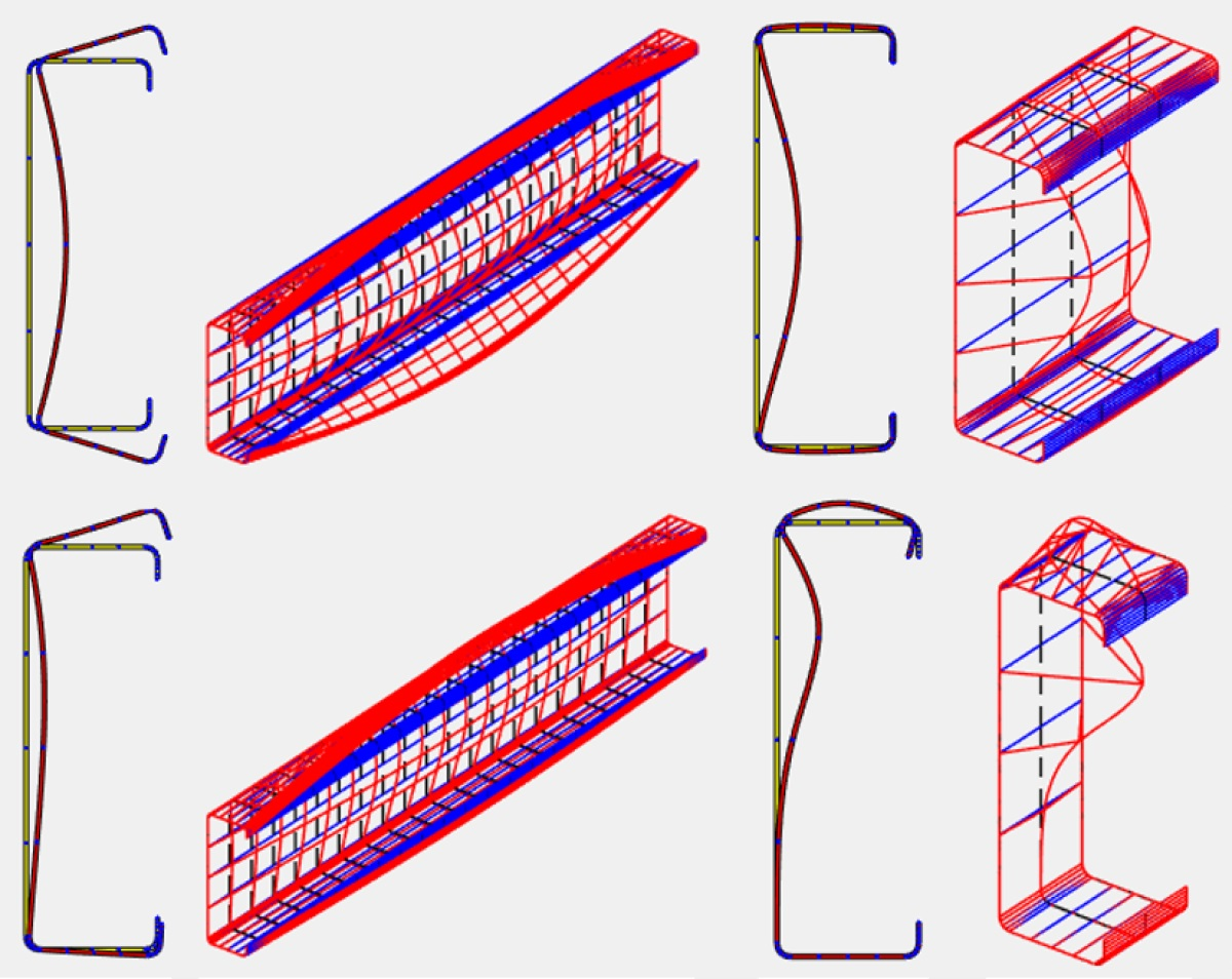
2.1. Local Buckling Behavior

Local buckling is the highest possible level of buckling in a compression element of a CFS component when the line connections and angles between the elements remain unchanged. It often happens when a particular element’s local buckling capacity is exceeded by the compressive stress in that element. Local buckling may affect the member’s overall stiffness and strength [3,7,8,9,12].
It is difficult to restrict the local buckling of CFS I-section columns when the screw spacing is equal and greater than the local half-wavelength (HWL) of buckling of the C-sections. Experimental results have demonstrated the presence of LD interaction in short built-up CFS columns, as well as LDG interaction in columns’ intermediate length [13]. Additionally, investigations have revealed that distortional and shear buckling are frequently observed failure modes in light gauge steel members [14].

2.2. Distortional Buckling Behavior

Excluding local buckling, distortional buckling is a buckling type in which the CFS’s cross-sectional (CS) geometry changes. It involves the section warping or distorting as a result of torsion and/or bending working together [3,7,8,9,12].
During numerical investigations into the double back-to-back (BC) lipped built-up columns’ axial strength, distinct modes of failure were identified. Short columns predominantly experienced local buckling as their primary failure mode. Conversely, columns with intermediate height exhibited an interactive local-overall distortional buckling failure mode. In contrast, long columns demonstrated an overall distortional buckling failure mode [15].
Regarding types 1 and 2 buckling, thumb’s rules apply for width/thickness less than 200 and 100, respectively (see Figure 2). Less than 3 mm of thickness is required [16].
In imperfection type 1:
d 1     0.006   w   d 1     6 t e 2 t
In type 2 imperfections:
d 2   t

2.3. Global Buckling Characteristics

It is a phenomenon that occurs in structural members, such as columns and beams, when they experience compressive loads or forces. It is a critical consideration in structural engineering to ensure the stability and safety of the overall structure [3,7,8,9,12].
For columns, there are three main modes of global buckling [3,7,8,9]:
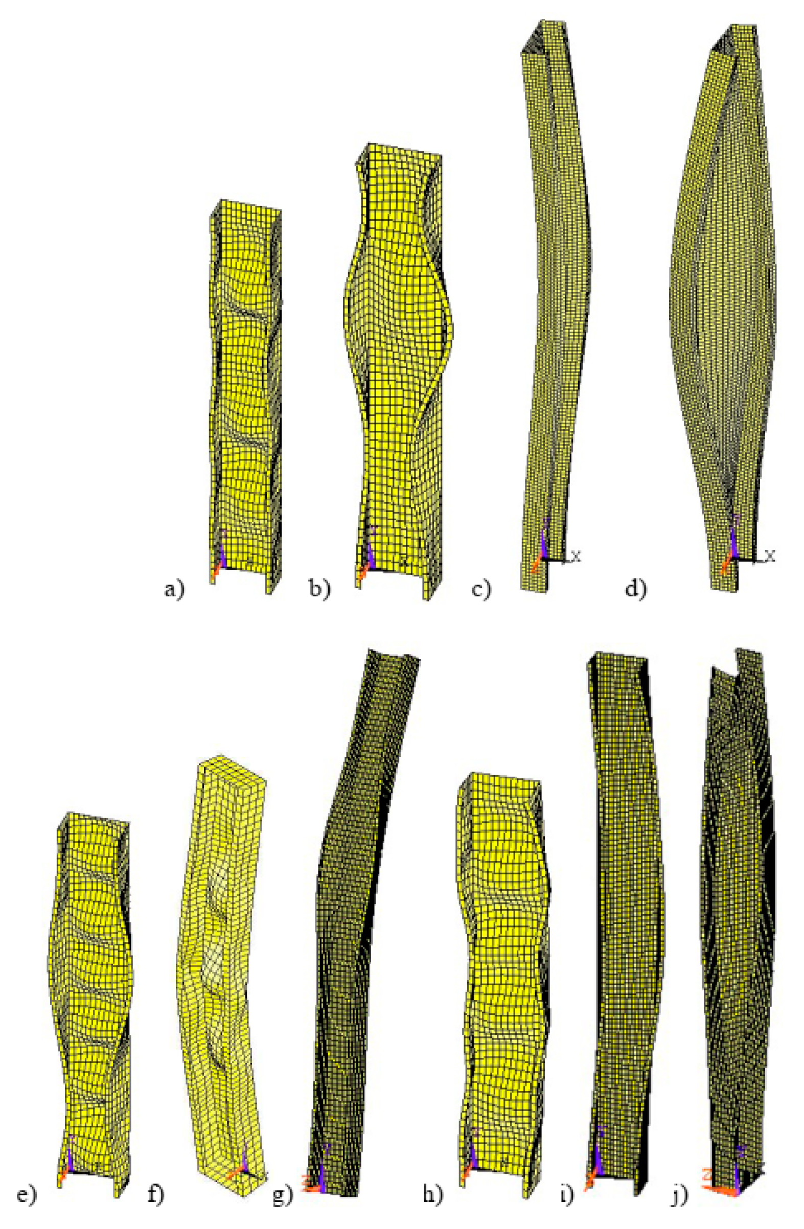
  • Flexural Buckling: This mode occurs when a compression element (column) laterally flexes without changing or twisting its cross-sectional shape. It typically happens when the column is slender and subjected to axial compression forces.
  • Torsional Buckling: In this mode, a compression member simultaneously bends and twists without changing the form of its cross-section. It occurs in columns that are slender and have significant axial torsional forces acting on them.
  • Flexural-Torsional Buckling: This mode is a combination of flexural and torsional buckling, where both bending and twisting occur simultaneously in a compression member without altering its cross-sectional shape.
For beams, the main mode of global buckling is called Lateral-Torsional Buckling [3,7,8,9]:
  • Lateral-Torsional Buckling: This mode occurs in flexural members like beams when they are subjected to combined lateral bending and torsional moments. The beam twists about its shear center while also deflecting out of the plane of bending.
In all cases, global buckling is a critical failure mode to consider when designing structures. Engineers must ensure that the members are adequately designed and reinforced to prevent such buckling behavior and ensure the safety and stability of the overall structure. Design codes and standards provide guidelines and equations to calculate critical buckling loads and to design members to resist global buckling.
A cold-formed multi-limb steel stub column, comprised of a single component with C- and U-shaped shapes joined using self-drilling screws, exhibits local buckling and distortional buckling as common failure mechanisms [17]. Although generally conservative, the modified slenderness technique is perhaps slightly unconservative, deviating by approximately ten percent for CFS stub columns that are put up back-to-back [18]. Furthermore, the presence of springs within CFS studs has negligible impact on distortional buckling and no influence on local buckling, yet they play a crucial role in preventing global buckling by providing constraint [19]. The study concludes that the smeared spring hypothesis can only be valid when the half-wavelength to connector spacing ratio for global buckling is less than 0.25 [19].

3. Behavior of Cold-Formed Steel (CFS) Members with Web Holes

Sections made of CFS that have holed webs are structural components commonly used in construction and engineering applications. These members are typically manufactured by cold-forming techniques, which involve shaping steel sheets or strips at room temperature. The presence of holes in the webs of these members serves various purposes, such as facilitating the passage of utilities like electrical wiring, plumbing, or ventilation systems. Furthermore, these holes can reduce the overall weight of the member while maintaining its structural integrity [2,20,21].
When designing CFS elements with hollows in the webs, careful consideration of factors such as load-bearing capacity, the distribution stress, and the holes’ impact on the overall stability of the structure is required. To ensure the safe and efficient use of such members, industry standards and guidelines provided by organizations like (AISI) or the International Code Council (ICC) outline specific criteria and design methodologies [2,20,21].
By incorporating holes in the webs of thin-walled elements, engineers and architects can optimize their designs, improve installation efficiency, and enhance the functionality of the overall structure. Additionally, this approach allows them to adhere to industry standards and regulations, ensuring the structural integrity and safety of the construction project [2,20,21].
The aluminum alloy columns placed in BC decreased their axial strength by fifteen to twenty percent as the ratio between the diameter of the hole and the depth of the web (a/h) increased from zero to four-fifths [22]. Additionally, the investigated sections experienced mean reductions of thirty-two percent and thirty-six percent in axial strength for plain elements and members with center web holes, respectively, as the modified mean slenderness ratio ((KL/r)m) increased from fifty-six to two-hundred-fifty. Furthermore, As the web hole diameter increased, the sections’ shear capacity dropped. Conversely, the section’s shear capacity improved when there was a greater separation between the web holes and the bearing plate [14].

3.1. Bending Response of CFS Members

Bending of CFS sections refers to the process of applying external forces or moments that cause the member to undergo curvature. This technique is commonly employed in construction and engineering applications to shape and form cold-formed steel into desired configurations. During the bending process, cold-formed steel members experience deformation and undergo changes in their cross-sectional shape, which can have a significant impact on their structural behavior. These changes can affect important characteristics such as the member’s capacity for bearing loads, stiffness, and resistance to lateral torsional buckling. Therefore, understanding the CFS sections’ behavior during bending is crucial for ensuring the structural integrity and safety of buildings and structures. By employing appropriate bending techniques and considering factors like the geometry of the sections, properties of the materials, and loads that have been applied, engineers and architects can optimize the design and performance of CFS elements in various construction projects [2,23].

3.2. Web Crippling Phenomenon in CFS Elements

Thin-walled steel elements’ web crippling refers to the local failure mechanism that occurs when the CFS sections’ web undergoes significant deformation or buckling due to excessive compressive loads or concentrated forces applied near the supports. This phenomenon typically affects beams and joists with thin webs, and it can lead to a decrease in the ability to carry loads and structural integrity of the member. Design considerations, such as appropriate web stiffening or the use of load distribution plates, are crucial in mitigating the possibility of crippling at webs and guaranteeing the secure and effective operation of CFS structures [2,21,24,25].
In the case of Zed with unequal angles, web crippling is less pronounced [14]. To prevent an excessive drop in web strength, it is advised that the built-up I-sections’ e/H ratio, when H stands for the overall web height and e is the distance between the flange’s outer surface and the center of the screws, should not exceed 0.3 [26]. Although the strength drop may not be immediately apparent, the crippling strengths of the webs of the I-shaped sections that have been constructed typically decrease as the ratio of e/H increases. Consequently, it is recommended to position the screws as close as possible to the flange-web joints to optimize performance [26].

3.3. Shear Behavior of CFS Sections

Shear in CFS elements refers to the internal forces that act parallel to the plane of the member, causing it to deform or fail. It is a crucial factor to take into account while analyzing and designing CFS Structures. When built-up CFS members are connected together, shear among the members becomes a critical aspect. This refers to the shear force transmission between the linked parts and ensuring their structural integrity. Using the right analytical and design techniques, including the use of appropriate fasteners and connection details, is essential to addressing shear in individual cold-formed steel members and shear between built-up members [2,27]. Moreover, the screw’s diameter and the thicknesses of the connecting plies affect the connection between shear force and displacement [28].

4. Design Considerations for Strength and Stability in Cold-Formed Steel (CFS) Structures

There are various factors and principles that need to be taken into account when designing structures made from cold-formed steel (CFS) to ensure their strength and stability. These considerations include:

4.1. Effective Width Method (EWM) in CFS

This design approach was first introduced in 1932 as an innovative method [29], subsequently in 1952 it underwent modification [30]. The fundamental tenet of the effective width approach is that local buckling reduces the efficacy of the plates that make up a cross-section [24,31].
This method is a widely used approach for CFS members’ analysis and design. It involves determining the effective width of the member based on its geometry and loading conditions, which simplifies the analysis process [32].
Advantages of EWM include its simplicity and ease of implementation. It provides a conservative estimate of the member’s strength and behavior, making it a reliable design approach. Additionally, the EWM allows for efficient calculation of the member’s capacity and facilitates quick design iterations [31].
However, the Effective Width Method has certain limitations and disadvantages. It assumes a uniform distribution of stresses across the effective width, which may not accurately capture the complex stress patterns in some member configurations. Consequently, the process might lead to a conservative design and potentially an overestimation of material requirements [31].
Moreover, the EWM does not consider the influence of local distortions or imperfections, which can affect the member’s behavior and strength. It is essential to supplement the analysis with other techniques or refinements to address these factors and ensure accurate predictions [31].

4.2. Direct Strength Method (DSM) in CFS

It is a design strategy used for CFS members that simplifies the design process just by predicting the behavior and strength of the elements without the need for extensive and time-consuming calculations [32].
The groundbreaking study from 1998 utilized the term Direct Strength Method for the first time [16] as they developed fresh cold-formed steel beam design techniques. About two decades ago, DSM emerged as a reliable alternative to conventional design techniques for CF thin-walled steel components. DSM is a possible utilization of structural design methodologies based on the generalized slenderness idea [33]. Its significance extends beyond CFS, as the DSM has gained global recognition for designing structural systems and thin-walled members, inspiring numerous numerical and experimental studies focused on validating, codifying, and advancing design approaches based on the DSM for a variety of structural issues [34].
DSM benefits for CFS sections include its efficiency, accuracy, flexibility, and cost-effectiveness. DSM eliminates the need for iterative design procedures and simplifies the analysis process, resulting in more effective design iterations and reduced design period. By directly predicting the strength and behavior of members made of CFS, DSM provides accurate results when compared to traditional design methods. Additionally, DSM allows for greater design flexibility by considering various factors like end boundary conditions, cross-sectional size, and material characteristics, enabling designers to optimize the member’s performance. This method can also result in cost savings by reducing material usage and allowing for more economical designs without compromising structural integrity [33,34].
However, for members made of CFS, there are a few limitations and disadvantages to the DSM. Firstly, its applicability may be limited to certain configurations or situations, and other design methods might be more appropriate in certain cases. The accuracy and reliability of DSM depend on the availability of experimental data and validation studies, which may be limited for specific member configurations, potentially affecting the accuracy of predictions. Additionally, designers and engineers need to familiarize themselves with the principles and application of DSM, which may require additional training and expertise to effectively utilize this method.
In the research on CFS buildings, the DSM’s predictions of the design strengths were contrasted with test findings and numerical data. It was found that when using DSM equations, various screw arrangements are not necessary to forecast the built-up open steel beams’ design strengths. In spite of that, the design formulae for local buckling strength in closed steel section built-up beams are often conservative [35]. Furthermore, the study on fixed built-up thin-walled steel columns arranged back-to-back demonstrated that the DSM design’s reliability equations, and suggested Critical Slenderness Ratio (CSR) exceeds the goal reliability (βo = 2.5) specified in (AISI-S100) [8] for LRFD [36].
Despite these limitations, the DSM offers significant advantages like efficiency, accuracy, flexibility, and cost-effectiveness for CFS members’ designs, making it a valuable tool in building construction as a discipline.

4.3. Factors Affecting the Strength of CFS Members

Cold-formed steel sections’ strength refers to their ability to withstand applied loads or forces without experiencing failure or deformation beyond acceptable limits. Several factors affect the strength of CFS sections, which can be categorized into material properties, section geometry, manufacturing processes, and loading conditions.
The columns’ axial compression strength with concentric loading reduces as either the height of the web-to-thickness ratio or the slenderness ratio increases. Built-up columns’ strength and stability are significantly enhanced by increasing the flange width. Additionally, the column’s eccentric axial compression strength, particularly around its weakest axis, experiences a more rapid decline compared to the strong axis [37]. The axial load capacity is something to keep in mind because it relies directly on factors such as the steel’s yielding strength (fy), different profiles’ cross-sectional areas, and the thickness of CFS profiles (t) [38]. Moreover, when the thickness of plates is increased, it leads to a reduction in the interaction between flexural and local buckling [39].
The CFS stub column with multiple limbs is constructed using individual U- and C-shaped parts, which are held together with self-drilling screws. The column’s entire performance, including its stiffness, buckling bearing capacity, and final axial compression bearing capacity is little affected by the spacing of these screws. However, the most significant factor affecting these properties is the plates’ maximum width-to-thickness proportion. As the thickness of the plates decreases, the width-thickness ratio increases, leading to a considerable reduction in the buckling bearing capacity [17]. Consequently, it can be concluded that the fasteners do not impact the torsion rigidity [28]. Furthermore, through the reduction of spacing between webs that connect the fasteners, the rotational stiffness at the juncture of the flange web is improved. This leads to increased critical distortional buckling loads when compared to what single sigma sections can achieve [40].
The addition of diagonal reinforcing bars welded to the web of back-to-back CFS I beams enhances their structural integrity in flexure zones and shear zones and significantly enhances their load-bearing capacity compared to beams lacking diagonal bars. Moreover, for comparison, consider beams that have and without diagonal bars; increasing the shear zone’s diagonal bars leads to a 1.1-fold increase in load-bearing capacity, while their inclusion in both the shear zone and the flexure zone results in a 1.4-fold increase. In contrast, beams lacking diagonal bars experience failure due to lateral buckling, whereas all other beams exhibit failure primarily through local buckling at the weld sites, accompanied by minor instances of lateral torsional buckling [41]. Regarding pinned-pinned, axially loaded Sigma CFS columns arranged in a back-to-back configuration and joined to their webs using fastening elements, the failure mechanisms vary depending on the column’s height. Short columns predominantly fail due to distortional buckling of the flanges, whereas columns of medium height demonstrate a distortional or local interactive overall sectional buckling mode. Conversely, large columns primarily fail through buckling overall. Furthermore, in members with larger web recess depth-to-thickness ratios, a reduction in the spacing between connecting fasteners induces the change from distortional to local buckling, like the prevailing failure mechanism [40].

4.4. Effect of Contact between CFS Sections in Assemblies

The effect of contact between cold-formed elements of steel that have been assembled within a structural system encompasses both positive and negative implications for its overall behavior and performance. When these sections are in direct physical contact, they can form a composite action that enhances load-carrying capacity and stiffness through the sharing of loads between adjacent sections. This results in a more efficient use of materials and improved structural integrity. However, contact between sections can also introduce challenges, including surface imperfections, misalignment, and variations in section properties, which can affect the load transfer mechanism and potentially reduce system performance. Inadequately designed and executed contact may cause premature failures, concentrations of stress, and local distortions.
The connector spacing and contact’s influence on Patterns of buckling in built-up samples have been observed; nonetheless, the ultimate carrying capacity of columns is only slightly influenced by the connection spacing when there is no significant global buckling between connections. Practical considerations led to the consideration of connecting spacings that were less than the local buckling half-wavelength [42].

4.5. Influence of End Conditions and End Fastener Groups (EFGs)

The Cold-formed steel sections’ end conditions, like beams and columns, have a considerable impact on the behavior and performance of the structures they support. The member’s connection to or support at its ends is referred to as the end conditions. Properly considering and addressing the end conditions is crucial for ensuring the stability, load-carrying capability, and overall structural integrity of the CFS members.
Particular consideration must be paid to the arrangement and properties of the fasteners used to link the separate components of built-up cold-formed columns’ end fastening groups. These fastener groups, often referred to as End Fastener Groups (EFGs), are responsible for joining the various sections of the CFS column together. The appropriate end fastener groups’ selection and design are vital for improving the ability to carry more weight and ensuring compatibility of buckling patterns consisting of multiple studs within the built-up member. It is recommended that the longitudinal dimensions of fasteners in EFGs be equal to or less than four times the screw diameters [8]. By adhering to this guideline, the structural capacity of the column can be effectively increased while promoting the desired buckling behavior.
The CFS columns’ ability to support loads increases when EFG is added, while the column’s capacity to support weight falls as web length increases [43]. Additionally, it has been demonstrated that an expensive EFG, comprised of a lengthy line of connectors at the extremities of each element, may increase columns’ capacity but only when they buckle under minor-axis flexure. However, EFGs are not significant in CFS constructions where distortional and local buckling control the breakdown mechanism and capacity of the column, as the majority of columns are sheathed and/or braced [39].
For fixed-ending columns, it has been proven that the strength predictions made by AISI and Eurocode are conservative [39]. In terms of buckling behavior, end circumstances play a big role in global buckling [44]. Conversely, conventional web-interconnections or sheathing have no appreciable impact on the CFS columns’ local buckling. While end conditions and web connections have a small impact on distortional buckling, sheathing, when properly accounted for with defined spring stiffnesses, has a significant positive impact.
According to a parametric analysis, altering EFG can greatly decrease the difficulty and cost of corrugated web built-up beam support without significantly affecting the stiffness and bending capacity of the beam [45]. This indicates that adjusting the end support conditions can be an effective way to streamline the construction process and save costs.
In the case of applying EFGs on CFS columns, it is ineffective for local buckling and only works for flexural buckling mode, especially for built-up back-to-back steel columns [46]. Furthermore, when fastener groups are inserted in flexure elements at the sites of the highest shear slip, the slide between the webs is significantly decreased [39].
In the presence of EFGs, composite action is created through the use of web screws, resulting in enhanced capacity and rigidity of CFS columns. Installing EFGs can improve the capacity of CFS columns by up to 33% and significantly enhance member reliability indices, particularly when there is a higher incidence of isolated global (flexural) buckling. Nevertheless, if local buckling interacts with global buckling, the EFG’s efficacy is diminished, leading to marginal reductions in buckling capacity and flexural deformations [47].
Nevertheless, it is essential to maintain a vertical spacing not exceeding four diameters, covering a distance equivalent to 1.5 times the built-up section’s maximum dimension [8]. Meanwhile, when the load is provided by the use of rigid end plates, the influence of end screw sets and end welding is minimal [28].
The experimental work indicates that the influence of the spacing of fasteners and EFGs on the capacity for local buckling and column resistance is rather minimal. Instead, it seems that connector spacing and EFG are less important than the boundary condition. Even if the web buckles appropriately, the column strengths and local buckling capabilities are not increased by the fastening design; instead, it affects the placement of local half-wavelengths [48].

4.6. Effects of Different Geometric Shapes on CFS Performance

Distinct geometric forms have distinct impacts on built-up CFS elements and are crucial in determining the behavior and performance of structural elements. The selection of geometric shapes, such as flange widths, web depths, and lip lengths, significantly influences the strength, stiffness, and stability of these members. Through comprehensive research and analysis, it has been observed that variations in geometric configurations can lead to variations in load-carrying capacity, buckling resistance, and overall structural integrity. Understanding and considering the effects of different geometric shapes is essential for CFS members’ optimization and efficient design in various construction applications.
An experimental program investigating the impact of various shapes on Cold-formed steel (CFS) beams that have been built up includes several specimens displaying two distinct Geometries of cross-section. The samples were built using simple channel components joined together using bolts (see Figure 3). Tensile coupons and a laser sensor were utilized to gather data in this study. In the first geometry, the channel’s top typically experienced buckling as the primary failure mode, primarily due to local buckling. Interestingly, the measured buckling half-wavelengths closely resembled the isolated component’s natural half-wavelengths, irrespective of the distance between connections. On the other hand, geometry 2 specimens also failed as a result of local buckling, but those with the widest connection spacing exhibited additional flexural-torsional buckling of the upper section between the points of connection. As the connecting space decreased, the final capacity of samples with Geometry 1 improved just a little bit. However, the connection spacing influenced the specimens’ ultimate capacity with Geometry 2. Specifically, increasing the spacing of the fasteners from 150 cm to 37.5 cm results in improvements of 11% and 36% in the ultimate capacity for the samples with the first and second geometries, respectively [49].
These findings highlight the influence of geometric shapes and connection spacing on the behavior of structures and the performance of built-up CFS sections. Understanding those effects is crucial for the design and optimization of such members in various construction applications.
According to reports, an open built-up part may have a lower weight-bearing capacity compared to a closed built-up column [50]. Moreover, the load-bearing capability of the section is known to increase with an augmentation in section thickness. Combining increased web and shear panel thicknesses in corrugated web built-up beams significantly enhances their flexural stiffness and bending capacity [45].
The structural characteristics of CFS columns with a triple C-section built up are heavily impacted by the maximum slenderness proportion. As the maximum slenderness ratio increases, both the capacity for axial compression and the stiffness of those columns noticeably decrease. However, variations in screw spacing from 150 mm to 450 mm have little effect on stiffness and the capacity for axial compression of CFS columns with quadruple C-channel construction. Therefore, screw spacing of 15 cm to 30 cm is considered acceptable, allowing the column’s individual parts to effectively function together. Furthermore, reducing the flange width-to-thickness ratio leads to an increase in the strength of axial compression of Columns made of CFS with four C-channel configurations [51].
It was noted that the geometry of the members changed when screws were used to form the built-up members (3C and 4C). While additional fasteners may enhance the built-up section’s composite action, the member’s strength might be negatively impacted by the distortions brought on by screw installation. Interestingly, the ultimate capacity of the test columns was only slightly increased by adding more fastener rows [52].
These findings emphasize the importance of considering section thickness, geometry alterations due to screw installation, and the highest ratio of slenderness in optimizing built-up CFS elements’ performance and design.

4.7. Temperature Effects on CFS Behavior

The effect of temperature on CFS sections is a significant consideration in their design and performance. Fluctuating temperatures lead to changes in the CFS elements’ mechanical properties, including yielding strength, elastic modulus, and thermal expansion. These variations, induced by temperature, can have an impact on the structural integrity and capability to bear a load of CFS sections. Consequently, engineers and designers must carefully consider these effects while designing and analyzing CFS members, implementing appropriate measures to mitigate any potential detrimental consequences resulting from temperature changes [53,54].
The accuracy of design equations for the tilting and bearing capacity of fastener connections within the present CFS design requirements for built-up CFS elements under ambient temperature settings has also been evaluated through experimental research. The study also looked at how well these design equations, when combined with suggested reduction factor equations specifically made for enhanced temperature capabilities, could be utilized to forecast the tilting and bearing capacity of fastener connections at high temperatures. Notably, the experimental testing showed that when temperatures rose, these connector connections inside built-up CFS members’ tilting and bearing capabilities decreased [55].
The primary objective of this research [56] was to assess and evaluate the rate of charring in wood connections under two different scenarios: one including the introduction of extra steel parts, and the other involving the use of gypsum plasterboards as a protective measure. The results of the study indicate that the rate of charring in wood sections is consistent with the values specified in Eurocode. However, it is observed that this rate changes depending on the density of the wood. The inclusion of steel parts, such as dowels or internal plates, resulted in an elevated incidence of wood charring as a consequence of internal heating subsequent to fire exposure. The steel material facilitated the transfer of heat into the connection, whilst the wood material initially provided insulation. This combination of materials contributed to the formation and growth of the char layer in the connection.

4.8. Impact of Connectors on CFS Structural Performance

Connector usage in set-up CFS sections significantly influences their structural performance and load-carrying capacity, as connectors play a crucial role in transferring forces between individual components, ensuring overall stability and strength of the structure.

4.9. Influence of Connector Spacing on Composite Action in CFS Systems

The space between fasteners in built-up CFS elements plays a significant role in achieving composite action. Optimal fastener spacing enhances the load-bearing capacity and promotes the effective transfer of forces between separate sections, thereby improving the overall structural behavior and performance of the built-up members.
The composite action’s degree achieved during the joining of separate sections significantly influences the built-up elements’ behavior. This partial combined effect is determined by the placement, connectors’ finite shear stiffness, and connector spacing. Specifically, the spacing of the connector is a key factor in how closed, built-up elements behave. Increasing the spacing of the bolts contributes to the local buckling of built-up members and diminishes the composite action, with a more pronounced reduction observed in square columns. To optimize the load-bearing capacity and ensure excellent composite action, it is recommended that built-up columns’ fastener spacing be equal to or less than the half-wavelength of the local buckling in cases where local buckling is high [57].

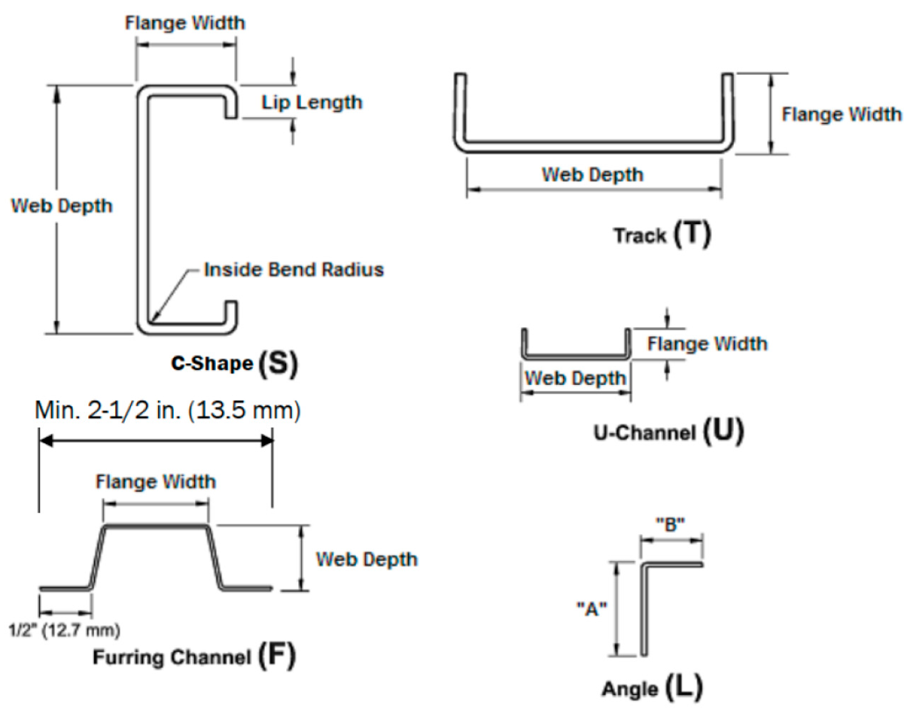
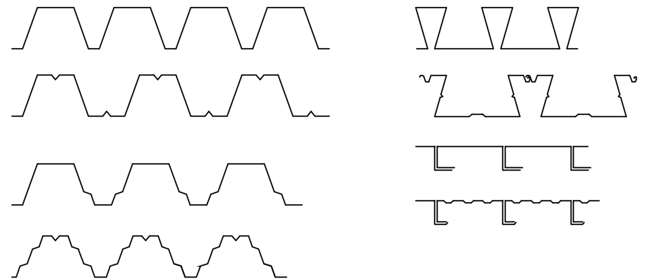
5. Types and Configurations of Cold-Formed Steel (CFS) Sections

The geometry and shape of single, open, and closed CFS members are very important in determining their structural behavior and performance. The design of these members considers factors including thickness, the web’s depth, internal bend radius, and length of the lip, which influence their load-carrying capacity, stability, and resistance to various forces and deformations. By carefully considering and optimizing the geometry and shape of CFS sections, engineers can ensure the efficient and safe utilization of these components in a variety of construction-related applications.
Individual open members closed built-up members, and open built-up members are some types of structural elements that may be made from cold-formed steel [4]. The standard dimensions of C-Shapes (S) indicate a varying range for web depth, from 41.3 mm to 356 mm, and a standard design lip length ranging from 4.8 mm to 25.4 mm. Furthermore, the design guidelines specify an inside bend radius between 2.141 mm and 4.732 mm (see Figure 4) [10]. The inside bend diameter of the junction between webs and flanges must not exceed four times the thickness ( d i /t ≤ 4) [9], although it is recommended to maintain a relationship between the inner diameter ( d i ) and the thickness (t) within the limit of two-point-five ( d i /t ≤ 2.5) [4].
CFS elements may be categorized into two primary categories. The depths of individual members vary between 50–70 mm and 350–400 mm, while their thicknesses range from roughly zero-point-five mm to six millimeters (see Figure 5). On the other hand, panels and decks typically have depths ranging from twenty to two-hundred millimeters, and thicknesses ranging from zero-point-four to one-point-five millimeters (see Figure 6) [4]. Generally, the depth of individual framing structural members in cold-formed construction falls within the range of 50.8 to 406 mm, with material thickness ranging from 0.836 to 2.997 mm. However, in specific applications such as transportation and building construction, there may be instances where the depth of individual members exceeds 457 mm, and the thickness is 12.7 mm or thicker [3].

5.1. Advantages of Cold-Formed Steel (CFS) Sections in Structural Applications

  • High Ratio of Strength to Weight: Cold-formed steel sections have a great ratio of strength to weight, ensuring the integrity of the structure whilst reducing the weight of the overall construction. This advantage is crucial in applications where lightweight materials are desired to reduce foundation requirements, transportation costs, and assembly time [3,14,49,54,58,59].
  • Design Flexibility: Cold-formed steel sections can be easily customized and fabricated into various shapes and sizes, allowing for versatile design options. This flexibility enables architects and engineers to create innovative and efficient structures with complex geometries [3,24,54].
  • Cost-Effectiveness: CFS elements are cost-effective because of their efficient production processes, reduced labor requirements, and readily available raw materials. Additionally, their lightweight nature can result in lower transportation costs and easier on-site assembly [3,14,54,58,59,60].
  • Sustainability: CFS members are environmentally friendly and sustainable. They might be recycled indefinitely without losing their structural properties, reducing waste and conserving natural resources. Additionally, their lightweight composition contributes to lower carbon emissions during transportation and construction processes [3,58,59,60,61].
  • At room temperature, there is neither shrinkage nor creep, resulting in more accurate detailing [3].

5.2. Disadvantages of Cold-Formed Steel (CFS) Sections in Construction

  • Susceptibility to Buckling: CFS sections, particularly slender profiles, are prone to buckling under compressive loads. Proper design considerations, such as adding stiffeners or bracing, are necessary to mitigate this issue and ensure structural stability [62,63].
  • Reduced Ductility: Sections made of cold-formed steel generally exhibit lower ductility as compared to sections made of hot-rolled steel. This reduced ductility may limit their ability to absorb energy during seismic events or high-impact loads, requiring careful design and detailing to ensure structural performance [20,64,65].
  • Sensitivity to Corrosion: In particular, cold-formed steel sections can corrode in moist or corrosive situations. The adequate use of safeguards like coatings, galvanization, or corrosion-resistant materials must be employed to enhance their durability and longevity [62].
  • Thermal Conductivity: In comparison with some other types of building materials, cold-formed steel sections have a higher heat conductivity. This property can lead to increased heat transfer through the building envelope, necessitating additional insulation to maintain energy efficiency [53].
  • Limited Availability of Design Codes: In some regions, design codes and standards specifically tailored for CFS elements may be limited as opposed to traditional steel sections made of hot-rolled. Designers must carefully navigate existing codes and ensure proper implementation of relevant design provisions [46,66,67].
  • Limited Load-Bearing Capacity: CFS members generally have lower load-bearing capacities as compared to hot-rolled steel sections, which may require larger cross-sections or additional reinforcement in certain structural applications [68,69].
  • Low fire resistance and the properties of a material may change at high temperatures. And decreasing ductility at high temperatures [53,54].

5.3. Manufacturing Process of Cold-Formed Steel (CFS) Elements

There are two primary classifications of steel: cold-formed steel (CFS) and hot-rolled steel (HRS). For HRS, the raw material is exposed to heat, while for clod-formed steel, the metal sheets are rolled and bent at room temperature [54]. The cold-formed steel is manufactured by two major methods: cold rolling and press braking [4,54].
Cold-formed parts are made by forming thin steel plates, usually with a zinc covering already applied. Sections are available in a variety of channel sizes, resulting in lightweight building elements that are mostly employed in low-rise housing developments or as secondary components. Connecting tools such as bolts, screws, welds, and rivets are often made of high-strength steel [70].
This section presents a comprehensive description of the production methods used for CFS elements, including press-braking, stamping, and roll-forming techniques [3,4,7,8,70].
  • Material selection: The first step in the manufacturing process is selecting the appropriate steel material. Cold-formed steel sections are typically made from low-carbon steel, which can be easily cold-formed without cracking or breaking.
  • Strip preparation: The selected steel material is first cleaned and processed into strips of the required thickness and width. The strips are then straightened to ensure they are perfectly flat.
  • Roll forming: The next step is roll forming, the process involves the passage of steel strips through a sequence of rollers in order to obtain the desired configuration. The rollers apply pressure to the steel strips, causing them to bend and form into the desired shape.
  • Cut-to-length: Once the steel sections have been formed, the materials are trimmed to the specified dimensions with a cutter or other cutting equipment.
  • Post-processing: After the steel sections have been cut to length, they may undergo additional processing, such as punching or drilling holes, bending, or welding, depending on the specific requirements of the application.
  • Quality control: Throughout the manufacturing process, quality control checks are performed to ensure that the steel sections meet the required specifications for strength, dimensions, and surface finish.
  • Packaging and shipping: Finally, the finished steel sections are packaged and shipped to the customer, ready for use in construction or other applications.

5.4. Material Properties of Cold-Formed Steel (CFS) Materials

This section will provide an overview of the CFS elements’ material characteristics, including strength, stiffness, and ductility [3,4,7,8,70,71,72].
In order to create CFS pieces, a steel thin sheet is bent into the desired forms using a series of rollers, without the need for heat. These sections are commonly used in construction as they offer several advantages, such as a great amount of strength relative to their weight, as well as convenience of manufacture, and the balance between cost and efficiency.
Here are some material properties of cold-formed steel sections:
  • Yield Strength: CFS members have a high yield strength; this denotes the amount of stress the steel can withstand without permanent deformation. The yield strength of CFS sections typically varies between 230 and 550 N/ mm 2 , depending on the kind and thickness (t) of steel used.
  • Tensile Strength: The tensile strength of CFS elements concerns the stress levels the steel can withstand before breaking. The tensile strength of CFS members varies between 310 and 700 N/ mm 2 , depending on the type and thickness of the steel used.
  • Elastic modulus is a measure of the steel’s stiffness. It refers to the stress quantity necessary to induce a predetermined strain amount in the steel. The elastic modulus for CFS members varies between 190 and 210 GPa.
  • Ductility: it is the steel’s ability to deform without fracturing. Cold-formed steel sections have good ductility, which allows them to absorb energy during loading and reduce the risk of catastrophic failure.
  • Fatigue Strength: CFS members’ fatigue strength refers to their ability to withstand repeated loading without failure. CFS sections’ static strength is often higher than their fatigue strength, and it depends on numerous variables, including loading types, the section’s geometry, and the surface conditions.
  • Corrosion Resistance: CFS members are susceptible to corrosion, which can reduce their strength and durability. To mitigate this, coatings and surface treatments are often applied to the steel.
  • Fire Resistance: Cold-formed steel sections have relatively low thermal conductivity, which means they are slow to heat up and transfer heat. This makes them a good choice for structures that require fire resistance.

6. Composite Action in Cold-Formed Steel (CFS) Structures

The composite action of CFS members that have been assembled or constructed by combining multiple components refers to the synergistic behavior achieved when two or more individual members are connected and interact with each other. This interaction leads to improved capability for carrying a load and structural performance compared to the total of the separate components acting independently. The composite action is primarily achieved through effective load transfer mechanisms, such as the use of connectors or fasteners, which facilitate the transfer of forces between the individual components. By connecting the elements securely, composite action ensures load sharing and distribution, leading to enhanced strength, stiffness, and overall structural integrity.
The amount of composite action produced when combining numerous elements significantly influences the behavior of built-up members. As a result, one of the most important concerns in the design of such parts is properly considering the partial composite action’s influence [28,57]. The extent of partial composite action is contingent upon the configuration and spacing of fasteners, as well as the connections’ finite shear stiffness. The arrangement of fasteners holds significance in governing the enclosed built-up sections’ behavior. An increase in the spacing of the connectors diminishes the composite action’s level and exacerbates local buckling in built-up members, particularly in square columns. In cases where local buckling governs the strength of built-up columns, it is advisable to maintain fastener spacing that is less than or equal to half the wavelength of local buckling. This recommendation ensures a high degree of composite action; consequently, the built-up member’s load-bearing capability is maximized [57].
Research findings indicate that the AISI and AS/NZS codes exhibit a notable level of over-conservatism, approximately 17% when compared to both experimental and numerical results for built-up box columns with their faces adjacent to each other [73]. Moreover, the implementation of fasteners for connecting the webs in the CFS columns that are back-to-back has been observed to foster composite action, resulting in a substantial enhancement of capacity, up to 21% [44].

6.1. Filling and Sheathing of CFS Sections

Filling and sheathing of built-up CFS sections Exert a pivotal influence in enhancing their structural effectiveness and meeting design requirements. The process involves filling the cavities within the sections with appropriate materials and adding protective sheathing layers. Filling the cavities of built-up sections helps improve their capability to bear a load and stiffness. This may be accomplished by utilizing materials such as concrete, lightweight concrete, or foam insulation. The filling material provides additional support and stability, reducing the risk of local buckling and increasing the overall section’s strength. Sheathing refers to the application of protective layers on the surfaces of the built-up sections. Commonly used sheathing materials include gypsum board, plywood, fiber cement board, or strand-oriented board (OSB). Sheathing not only enhances the fire resistance of the structure but also provides lateral bracing, improves overall stability, and reduces global and distortional buckling effects.
To treat both distortional and local buckling, Filling the gaps is one successful strategy in opened and closed built-up sections with oriented strand board (OSB) [58]. Additionally, significant enhancements in ultimate capacity and stiffness can be achieved by reducing the spacing between fasteners. For instance, when members are attached to sheathing made of gypsum plasterboard and oriented strand board (OSB), capacity can increase by up to 12%, while stiffness can improve by up to 10% under pure compression conditions. Furthermore, bending tests have demonstrated improvements in stiffness and capacity of up to 22% and 26%, in each case. Notably, the fastener spacing starting at 300 mm and decreasing to 75 mm can result in a remarkable 29% capacity increase for specimens subjected to combined bending and compression [74]. It should be noted that CFS elements, which are manufactured by shaping thin steel plates, are typically coated with zinc in advance [70].
Regarding the behavior of CFS columns, their response can be examined from three perspectives. Firstly, local buckling remains unaffected by sheathing, boundary conditions, and usual web interconnections. Secondly, buckling that causes distortion shows modest sensitivity to end conditions and web interconnections, while the presence of sheathing significantly enhances performance, and this effect can be accounted for by properly calculated spring stiffnesses. Lastly, global buckling is heavily affected by end conditions, as noted in a previous study [44].
From a practical standpoint, it is advisable to ensure that fasteners in EFGs have longitudinal dimensions equal to or smaller than four times the screw diameters. This approach is essential for enhancing the load-carrying capability and encouraging consistent buckling modes among individual studs within a constructed composite section, particularly in the absence of sheathing [75]. Furthermore, for CFS-built-up batten columns, the ultimate load-bearing capability of a column increases as the slenderness ratio lowers. These columns are made up of four cold-formed angles made from thin sheets that are joined by 2 mm-thick batten plates [76].

6.2. Challenges of Inadequate Guidelines for CFS Composite Elements

The current state of design guidelines, standards, and books for the design of built-up CFS elements utilizing fasteners like bolts and screws is deemed inadequate. Insufficient provisions and guidance exist in these resources, leading to challenges and limitations in the design process. The absence of comprehensive guidelines poses obstacles when engineers and designers attempt to incorporate fasteners into the construction of CFS sections that have been joined. The lack of clear instructions and standardized procedures hampers the accurate determination of appropriate fastener types, dimensions, and spacing, as well as their overall impact on the structural performance of the sections.
Insufficient and accurate design standards, guidelines, and specifications are available for built-up CFS members, particularly when utilizing screws, bolts, and blind bolts [46]. Previous research has demonstrated that for members with a predominance of distortional and/or local buckling modes, the DSM design principles given by certain research are inappropriate, while the design standards currently in place exhibit a conservative approach [66]. Furthermore, the failure load of these sections is influenced by the spacing and arrangement of fasteners, yet accurately predicting these effects based on existing experimental data remains a formidable task [67].

6.3. Stiffeners in CFS Assemblies

Stiffeners are essential in enhancing CFS members’ structural performance. By strategically placing stiffeners within the sections, particularly along the web and flange elements, their load-carrying capacity and overall stability can be significantly improved. Stiffeners effectively resist buckling and increase the flexural rigidity of the sections, enabling them to withstand higher loads and mitigate deformations. Proper design and placement of stiffeners in CFS elements are essential considerations to ensure the structural integrity and optimal performance of these elements in various applications and load conditions [64].
The presence of a stiffened element within the cross-section significantly impacts the stub columns’ ability to carry axial loads. The capacity for carrying an axial load is greatly increased by increasing the number of stiffeners via the web and flange [38]. Experimental tests have shown that the bending stiffness of beams is only minimally influenced by elements like web openings, web beads, and connection spacing along the flanges [77]. When considering the CFS stubs’ ability to bear loads, the addition of stiffeners on the lips leads to an increase. However, compared to embedding stiffeners in the web, adding stiffeners at the point where the flange and web meet does not significantly increase load capacity [78]. Furthermore, the effective flexural rigidity experiences growth through the square of the space between the connections, the length between the neutral axis, and the connectors’ shear stiffness [28].

6.4. Conservative

When designing built-up CFS members that utilize fasteners like bolts and screws, it is essential to consider the conservatism of guidelines, standards, books, and finite element software commonly employed in the design process. These resources play a critical role in providing design recommendations and structural analysis tools. However, it has been observed that these references and software often exhibit a certain level of conservatism in their design provisions for built-up CFS elements using fasteners. This conservatism implies that the prescribed design guidelines and standards may result in structures that are more conservative, i.e., structurally safer but potentially overdesigned, than necessary.
Several research studies have examined the suitability of design guidelines for various structural members and compared them to current design standards. When failures caused by local or distortional buckling modes occur, it was determined that the DSM parameters for design established in earlier research investigations were unsuitable, whereas the current design standards were deemed conservative [66]. Additionally, the interactive buckling design curve, as specified by AISI, was found to be unconservative for CFS-linked built-up columns that are back-to-back and have unlipped channels [79].
The outcomes of the finite element (FE) results and the experimental tests for short, intermediate, and slender back-to-back CFS columns that have been built up, which experienced the use of both local and global buckling as well as global buckling, demonstrated conservatism compared to the design standards. However, for CFS stub columns, it was determined that AS/NZ and AISI standards were not conservative enough [18]. Moreover, the finite element results indicated conservatism in the design requirements for slender, intermediate, and short columns that fell due to either global buckling alone or a combination of global and local buckling. The AS/NZ and AISI guidelines, however, were found to be unconservative in the case of stub columns made of CFS that collapsed as a result of local buckling. Furthermore, these standards were determined to be beneath conservative by about 8% in cases where local buckling was primarily the main cause of built-up CFS column failure and too conservative by approximately 15% in cases where built-up CFS columns collapsed due to overall buckling [80]. Additionally, a comparison of the outcomes showed that the AS/NZS and AISI guidelines are generally unconservative for columns that collapsed due to local buckling in particular but conservative for all columns that failed due to overall buckling, with a discrepancy of approximately 12% [81].
Specifically examining back-to-back columns made of aluminum alloy, for intermediate columns that failed primarily due to distortional and global buckling modes [22], it was discovered that the design strengths of AS/NZ and AISI were conservative by 15%. Similarly, for stainless built-up columns facing opposite one another, around 15% conservatism was shown by the AS/NZS and AISI standards for failures caused by global buckling, but they were unconservative by approximately 5% for failures attributed to local buckling [82].
Comparing the experimental results, it was determined that AISI-S100/2016 and AS/NZS-4600/2018 showed a 10% unconservatism and a 6% conservatism, respectively, for the ultimate and initial failure loads of T-stub connections made of CFS [83]. Moreover, for fixed-ended columns, the predictions of strength by AISI and Eurocode were shown as being conservative, while the IS code was generally more conservative than the AISI specification [14]. Additionally, an assessment of web crippling resistances using experimentally and numerically generated data showed that the current design rules and formulas used in EN1993-1-3, AS/NZS, and AISI could provide results that were either extremely unsafe or conservative [26].

7. Connection Types and Methods Used in Cold-Formed Steel (CFS) Sections

CFS connections refer to the methods and techniques used to join and integrate various cold-formed steel sections into a cohesive and structurally sound system. Cold-formed steel refers to steel that has been formed at room temperature or below, typically through processes such as roll forming or pressing. It is characterized by its thin cross-sections and high ratio of strength to weight.
Those connections are of utmost importance in guaranteeing the overall stability and ability to bear loads in CFS structures. In order to fulfill the particular demands of the project, it is essential that they be meticulously crafted and implemented, including factors like load capacity, durability, and constructability.
It’s important to note that the selection of a suitable connection type for CFS elements is determined by various factors, including the structural design, intended use, applied loads, and local building codes and regulations. Consulting with a qualified structural engineer or a professional experienced in the CFS framework is highly recommended to ensure the proper design and implementation of connections in such structures.

7.1. Screw Connections in CFS Components

Screw connections involve using self-tapping screws or bolts to connect two or more cold-formed steel sections. These connections provide ease of assembly and disassembly and are suitable for non-permanent or modular structures [3,4,7,8,9,24].
Screws with diameters ranging from 0.203 cm to 0.635 cm [3,5,7,8,10] are now being used. On the other hand, as stated in reference [9], screws that self-tap within the range of 0.3 cm to 0.70 cm in nominal diameter are used in situations involving non-dynamic loads. The screws in question possess the capability to either create threads or cut threads, and their design may or may not have a self-piercing tip. According to several sources [3,5,7,8,9,10], it is recommended that the minimum gap between the centers of connectors should be at least three times the diameter. Similarly, the minimum space from the center of a connector to the edge or end of any component should not be less than 1.5 times the diameter [3,5,7,8,9,10].

7.2. Welded Connections for CFS Members

Welding is a widely used method to join thin-walled steel members. It involves melting the metal at the joint to create a fusion between the sections. Welded connections offer excellent strength and rigidity but require skilled labor and appropriate welding procedures.
When resistant spot welding (SWs) is used for connecting CFS beams, when there is a rise in the pitch distance, there is a corresponding reduction in the load-bearing capability. The space that exists between each of the SWs on the elements, almost little effect is seen on the behavior of the beam. However, enhancing the spot welding’s quantity, specifically from two to three lanes on the sections’ web, might potentially impact the enhancement of the final bending capability, while it is worth noting that the initial stiffness of bending stays relatively unchanged [45]. Furthermore, it should be noted that the failure of the BC plain screwed member with two axes of symmetry occurs due to plate buckling in the middle. On the other hand, it has been observed that the face-to-face (FF) plain welded elements with two axes of symmetry experience failure due to flexural buckling either at the mid-length or at the bottom or top corner, as documented in reference [78].
There are many different kinds of welds, such as fillet, groove, slot, and plug welds, and others [10,71]. The design of welded connections that are utilized for CFS components and have a thickness of 1.830 mm or less in the thinnest connected element [7,8]. On the other hand, the thicknesses of the weldable steel sections must be equal to or greater than four millimeters in accordance with EN 1993-1 [71]. The ends of a built-up compression member are joined either by a weld that is longer than the maximum element’s width or by connectors that are longitudinally placed not more than four diameters apart over a distance that is equivalent to one point five times the member’s width [8]. The weld length must not be less than the maximum section width.

7.3. Riveted Connections in CFS Structures

Riveting involves the use of metal fasteners called rivets to join steel sections. This method requires punching holes in the sections and then inserting and securing the rivets. Riveted connections offer good strength and durability, but they are less commonly used in modern construction compared to screw or welded connections.

7.4. Bolted Connections for CFS Applications

Bolted connections involve using bolts and nuts to connect steel sections. Holes are drilled through the sections, and bolts are inserted and tightened with nuts. Bolted connections provide ease of installation, maintenance, and disassembly. They are commonly used for temporary structures or when on-site assembly is required.
Connections made with bolts are employed in the context of CFS structural elements when the thickness of the thinnest linked component is 4.760 mm or less [7,8]. Nevertheless, it is essential that the separation between the centers of connectors not be smaller than three times the nominal bolt diameter (3 d). Furthermore, it is essential that the minimal distance between the centers of bolt holes allows for sufficient space to accommodate bolt nuts, heads, wrenches, and washers. In the case of large and slotted holes, it is required that the smallest gap between the edges of two consecutive holes be equal to or greater than 2 d [3,5,7,8,9,10]. However, as stated by reference [71], it is necessary to ensure that the minimum spacing between bolts is two-point-two times the diameter (2.2 d). Conversely, it is essential that the measurement between the central point of a fastener and the periphery or extremity of any component does not go below a value of one-point-five times the diameter of the bolt (1.5 d). In the case of holes that are larger than standard or include slots, it is required that the separation between the hole’s edge and the edge or end of the component should not be less than the specified value d [3,5,7,8,9,10]. Conversely, it is necessary to adhere to the stipulation that the bare minimum separation between edges and ends should be one-point-two times the diameter (d) [71].

7.5. Clip Connections in Cold-Formed Steel (CFS) Systems

Clip connections, also known as connector plates or cleats, involve using pre-fabricated steel plates with pre-punched holes. These plates are attached to the steel sections using screws, bolts, or welding. Clip connections are frequently seen in frame systems made from thin sheets of steel.
The most important point is that when combining two channels into an I-section, the optimum longitudinal gap of any welds or other connections ( S m a x ) must be equal or less than the length of the member divided by six [3,7,8,9].

8. Design Considerations for Screw Spacing and Fastener Restrictions

When considering the design of built-up CFS beams, it is important to exercise meticulous deliberation while determining the appropriate spacing for screws and fasteners, as well as the corresponding restrictions. The proper placement and spacing of fasteners play a critical role in achieving the desired composite action, local buckling resistance, and overall structural integrity. In addition, by complying with prescribed limitations, it is ensured that the slenderness ratio of the constructed composite element does not exceed the designated threshold. This serves to mitigate potential failure mechanisms and enhance the structural integrity of the beams, thereby improving their ability to bear loads. By appropriately addressing these design considerations, the enhancement of reliability and performance in built-up CFS beams may be efficiently achieved.
Moreover, within the realm of design practice, it is advisable to adhere to the guideline that the maximum spacing of the screw longitudinally for built-up beams consisting of two C-sections placed in close proximity should not surpass four times the total web depth ( S l ≤ 4 h w ) [35]. Moreover, to ensure structural integrity, it is essential to restrict the distance between adjacent fasteners or welded spots according to the condition (a/ r i ≤ 0.5* KL/r), with the goal of not exceeding fifty percent of the governing slenderness ratio of the constructed member [8].
On the other hand, it has been established that the adjusted slenderness ratio is applicable solely to regions with low fastener spacing (S r o / KL r i ≤ 0.2). At high fastener spacings, the primary factors that significantly affect the built-up column’s strength are the shear slip occurring between the different sections and its relationship with flexural buckling. These characteristics, which are not included in the MSR method, have a major role in determining the overall strength of the column [36]. It is important to acknowledge that intermediate fasteners or welds located at every longitudinal member tie position have the ability to transfer a force in either direction that is equal to 2.5% of the built-up member’s nominal axial strength (compressive resistance) [8].

8.1. Effects of Fastener Spacing on Compression Strength and Buckling

Fastener spacing in built-up CFS columns plays a critical role in their buckling and compression strength. Increasing the spacing between fasteners has been found to promote local buckling of individual components and consequently diminish the built-up member’s composite action. The columns’ axial load capability may decrease if the fastening spacing is reduced, particularly in sections featuring cover plates. Therefore, careful consideration of fastener spacing is essential to optimizing the built-up CFS columns’ superior performance and load-bearing capability.
The findings of the study indicate that the use of discrete fasteners may effectively improve the overall built-up open-section columns’ buckling capacity, irrespective of the existence of web stiffeners [84]. In the compound strip method (CSM) stability investigation of CFS built-up columns, it came to our attention that the specific configurations of screws had minimal influence on the moment capacities of constructed open-section beams. Fortunately, the distance between fasteners had a more significant effect on built-up closed-section beams’ moment capabilities [35]. Significantly, while conducting a comparison between samples possessing a single row of fasteners in the moment span and those featuring two rows, both groups exhibited identical structural behavior [35]. Furthermore, an increase in fastener spacing was found to promote buckling of the built-up section’s individual components, and this phenomenon ultimately results in a decrease in the axial load-carrying capability of CFS-built stub columns to withstand axial loads. This effect was particularly noticeable in section profiles featuring cover plates [38]. Nevertheless, during stub column testing, it was observed that reducing connection spacings could result in an improvement in ultimate capacity by up to 11% [85]. Although the augmentation of the quantity of screws had minimal impact on the stub’s axial strength and thin columns, it did influence the strength of columns that are short and intermediate. When considering short columns, increasing the distance between screws by a factor of two resulted in a decrease in section strength of approximately five percent to ten percent, while intermediate columns experienced a reduction in strength of ten percent to fifteen percent with increased screw spacing [81].

8.2. Impact of Screw Spacing on CFS Built-Up Column Capacities

The research studies have demonstrated that reduced accumulated CFS Columns’ screw spacing can significantly enhance their load-carrying capacities. By decreasing the spacing between screws connecting the steel sheets, the overall structural integrity and stiffness of the column can be improved, resulting in higher load resistance and improved structural performance. This finding underscores the importance of proper spacing and placement of screws in CFS built-up columns’ construction and design to optimize their load-carrying capabilities.
Furthermore, it has been observed that connection spacing has a limited influence on CFS built-up column final capacity [86,87]. Numerical and experimental tests have shown that screw spacing has a negligible effect on built-up closed box section columns’ compression strength. The compression strength exhibited a consistent variation of less than three percent when the spacing between screws was adjusted between 15 and 45 cm. This finding suggests that the overall strength of the constructed column is only slightly greater than the combined strengths of its individual components [37]. The results of this study indicate that the compression behavior and capacities of BC sections are not significantly influenced by screw features and arrangement in situations where failures are mostly caused by local or/and distortional buckling modes. Research has shown that the compressive capacity of BC members may be regarded as double that of single-channel elements. However, to ensure complete web buckling compatibility, the screw spacing in these BC components may need to be much smaller than the half-wavelengths related to distortional and local buckling modes. [66].
Additionally, screw spacing’s effect on stainless stub columns’ axial strength was found to be minimal across all three classes. Nevertheless, doubling the vertical distance between fasteners resulted in a reduction of approximately 5%, 12%, and 22% in the axial strength of columns of varying lengths, such as those that are short, intermediate, and long [82]. In the case of nested channel (NC) members, there was a small increase in compression strength with a 3% increment in changing the screw spacing from the ratio of length divided by two to length divided by twenty. Local buckling of NC sections was found to have minimal influence on their compression behavior and capabilities [88]. With a web width-to-thickness ratio that was rather low, the influence of fastener spacing on BC sigma CFS components was insignificant, while members were characterized by a significant ratio of web width to thickness. experienced a significant decrease in ultimate strength as fastener spacing increased [40].
To ensure the prevention of local failure and the simultaneous ability of individual members to carry loads in built-up columns and structures, several structural precautions should be taken at the column ends. Except for built-up studs, a minimum of three intermediate fasteners are required [67]. For the prevention of individual stud buckling prior to the failure of the whole built-up member, fasteners should be evenly spaced along the length [39]. It should be noted that the addition of overlaid plates does not enhance built-up sections’ local buckling capability, although built-up box section components’ distortional buckling capability may be increased to some degree by flange constraint [67].

8.3. Screw End Distance Impact

In built-up CFS elements, the length between the center of a fastener and the edge or end of any component significantly influences its structural integrity and performance. Ensuring an adequate distance helps prevent stress concentrations, reduces the risk of premature failure, and enhances overall load-carrying capacity. Proper design considerations and adherence to industry standards regarding connector placement play a crucial role in optimizing the durability, safety, and strength of CFS structures.
Increasing the columns’ width-to-depth ratio (B/D) with the same slenderness ratio has been found to contribute to an augmented ultimate load. Furthermore, in the case of long columns, it is advisable to maintain specific recommendations for the end interconnector spacing and the intermediate interconnector spacing. Specifically, the end interconnector spacing should be twice the cross-section depth, while the intermediate interconnector spacing should also be twice the cross-section depth, except for being halved. Notably, varying the spacing between interconnectors does not yield significant changes in the ultimate loads, as indicated by numerical results [15]. To enhance the bearing strength of the column and prevent end-bearing failure, it is recommended to maintain a 20 mm distance for the placement of the bolt [87].

9. Failure Modes and Design Considerations for Built-Up CFS Columns and Bolted Connections

The crucial design consideration for built-up columns made of cold-formed steel placed back-to-back against one another and bolted connections is to carefully analyze and mitigate potential modes of failure Examples of phenomena that may be seen are local buckling, bolt shear, and connection slip. By appropriately sizing and spacing the bolts, selecting suitable materials, and accounting for anticipated loads and structural behavior, engineers can ensure the structural integrity and performance of these systems.
The failure modes of cold-formed steel (CFS) columns without lips, placed in a back-to-back configuration are influenced by the impact of intermediate spacing. Notably, the ultimate load (Ptest) is significantly affected by the spacing of intermediate screws. The failure mechanisms of doubly-symmetric CFS columns have been documented as being either flexural torsional buckling or interactive buckling resulting from significant spacing between connections. Additionally, test results have shown a rise in the intermediate screw spacing (a) and an augmentation in the local slenderness ( λ l ) leads to a higher likelihood of local-global interaction buckling [79].
Also, it should be noted that the compressive strength of fixed-ended, long, back-to-back, built-up cold-formed steel (CFS) compression elements could be stronger than the combined strength of their individual parts. This outcome is contingent upon several factors, such as the specific properties of the sections, the spacing between them, and the amount of screws present in each row. Introducing two screws per row instead of one has led to a compression capacity increase of 5 to 16%. It is important to point out that these members are not prone to buckling in the torsional or flexural-torsional modes, respectively, as supported by test and FE analysis results [89].
In addition, experimental and numerical tests were conducted to determine the effect of fastener spacing on column length. The stub columns’ strength is not significantly affected by the number of screws; however, it has a profound effect on the low and mid-height columns’ strength. Doubling the space between screws in short columns led to a reduction in section strength of 5% to 10%. In contrast, the intermediate columns exhibited a reduction in strength ranging from around 10% to 15%. The long configuration of the BC-built-up CFS columns with varying screw spacing did not exhibit significant differences in strength, as their primary failure mode was overall buckling [18].
In relation to bolted beam-to-column connections in CFS structures, it has been shown that folded flange beam sections using diamond or circular bolt arrangements exhibit superior energy dissipation capabilities and ductility when compared to typical flat-flange sections employing a square bolt configuration. The use of gusset plates that possess a thickness equivalent to or lower than that of the cold-formed steel (CFS) beam may result in an untimely failure mode, causing a substantial reduction in the connection’s moment capacity. The long nature of cold-formed steel (CFS) beam components and the precise placement of bolts are significant factors that contribute to the determination of connection capability. In general, it has been observed that a square bolt configuration has a greater moment capacity, with potential increases of up to thirty-two percent when compared to other arrangements. The ductility of a structure is affected by various factors, including the arrangement of bolts, the shape of the beam cross-section, and the slenderness ratio. It has been observed that folded flange sections demonstrate notably greater ductility compared to curved, flat, and stiffened flat sections. Specifically, the ductility of folded flange sections can be up to fifty-five percent higher than that of curved sections, forty-five percent higher than that of flat sections, and thirty percent higher than that of stiffened flat sections when considering the same beam slenderness ratio and bolt arrangement. The ductility of a beam may be enhanced by using circular and diamond bolt arrangements, as opposed to the conventional square bolt configuration. The effectiveness of these arrangements is contingent upon factors such as cross-sectional shape and the beam slenderness ratio [90].
Additionally, the fasteners’ spacing ratio has a significant role in determining the built-up open and closed members’ buckling capacity, namely in both the global and local buckling zones. Changes in fastener spacing have a more pronounced impact on global buckling under clamped end conditions, whereas the impact on local deformation differs from case to case. However, in the zone that exhibits moderate buckling length and where no interaction between sub-sections is assumed, common fastener spacing ratios have minimal influence. However, the composite action and buckling capabilities in this particular area may be improved by integrating fasteners that are uniformly spaced and do not exceed a specified maximal value [91].
The built-up box beams’ buckling modes are controlled by the distance between connections. Local buckling occurs when the space between connections is less than or equal to the length of the beams divided by four; when the spacing exceeds the length of the beams divided by four, it results in the occurrence of mixed modes of distortional and local buckling, as well as lateral torsional buckling. Hence, it is advised that the distance between connections while constructing the box beam should be equal to or less than one-fourth of the length of the beams; thus, the beam’s flexural capacity increases with both increased thickness and decreased connection separation. Beams with a low ratio of flange width to thickness and a high web height are susceptible to buckling [92].

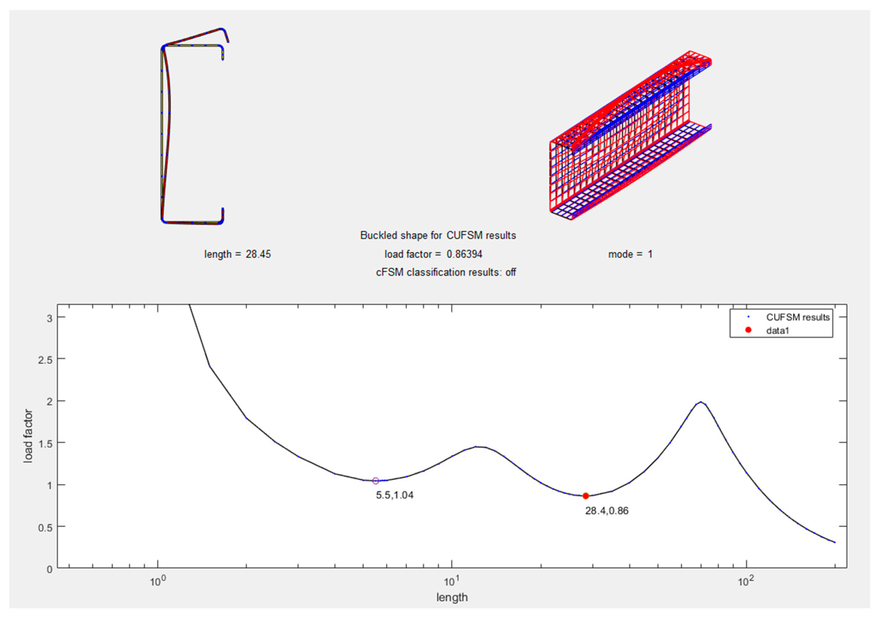
10. Methodology Employed in the Study of CFS Structures

The design methodology for CFS elements involves the application of structural engineering principles to efficiently and safely design structural elements made from cold-formed steel. This process includes analyzing the structural requirements, determining the loads and forces acting on the members, and utilizing established specifications and design guidelines to guarantee CFS components’ performance and structural integrity. The design methodology considers factors such as material properties, section properties, stability, and connections while incorporating appropriate design formulas, techniques, and considerations specific to CFS frameworks. The goal is to make CFS sections that are efficient, cost-effective, and reliable, as well as match the design criteria and standards for different uses in the development sector.
The methodology of designing and finding various buckling and strength capacities of CFS sections is essential for structural engineering analysis. The cold-formed steel (CFS) members’ design approach includes determining overall and nominal axial strength for each kind of buckling: global buckling (GB), distortional buckling (DB), and local buckling (LB). Similarly, it involves evaluating the flexural strength that is considered to be nominal for LB, DB, and GB, and the overall flexural resistance.
The method also gives you the chance to use computational tools like CUFSM with DSM to automate the design process. [93]. A traditional FSM model taking rounded corners into account is employed to calculate the buckling loads. There is no need for additional analysis if the generated signature curve contains distinct minima.
Due to their numerous advantages, in recent years, there has been a growing demand for CFS. However, designing CFS requires a great deal of care and attention to detail. To ensure the best possible design outcome, it is essential to follow a step-by-step approach.
The first step in CFS design is to calculate the column’s Nominal Axial Strength ( P n ) and the beam’s Nominal Flexural Strength ( M n ). There are two ways to obtain these values: practical and theoretical methods. Theoretical methods can be further divided into numerical and analytical.
To efficiently design and evaluate built-up cold-formed parts, there are multiple techniques that can be utilized. These techniques include:
Numerical methods encompass the application of Finite Element Methods (FEM), like Abaqus or Ansys, which employs computer software to assess stiffness and strength of the cold-formed sections, and the utilization of Finite Strip Methods (FSM), for example, CUFSM or cFSM. Analytical methods, and Hand Calculations. On the other hand, involve using books and standards such as AISI S100-16, AISI-D100-08, AISI-S240-20, ANSI/AISC 360-22, AS/NZS 4600-2018, ASTM, Eurocode three (part-1-1), Eurocode three (part-1-3), and Eurocode three (part-1-8).
To obtain accurate results, it is important to use a fine mesh size when using numerical methods. For analytical methods, there are simple and precise methods to determine P n and M n .
One practical method to determine P n and M n is to use Abaqus. First, the section is modeled in Abaqus and assign properties to it. After running the model, which may take several hours, the outcomes are observable. The output includes F cre , F crd , and F crl , as well as M cre , M crd , and M crl . One of the standards indicated in the analytical approach section may be used to determine the values of P n and M n .
In order to obtain more precision in the outcomes, it is advisable to use a finer mesh size. In the context of cold-formed steel (CFS) analysis, the selection of meshing size is subject to variation depending on the specific project requirements. However, it is generally advisable to opt for a meshing size that is equal to or smaller than five millimeters by five millimeters. This choice ensures a finer level of discretization and can contribute to more accurate and reliable numerical simulations when dealing with CFS structural elements.
An alternative method for ascertaining the values of axial load ( P n ) and moment ( M n ) entails the utilization of the (CUFSM). Should the software contain the requisite section profile, it can be selected for analysis. In cases where the section profile is not available within the software’s library, it can be manually generated using the specified code provided earlier. Upon executing the software, a set of results is obtained, encompassing parameters such as P Cre / P y , P Crd / P y , P Crl / P y for columns, and M Cre / M y , M Crd / M y , M Crl / M y for beams. Subsequently, P y and M y are determined utilizing the following expressions: P y = F y * A g and  M y = S f F y , where F y represents the yield strength of the material and A g signifies the gross area. Finally, the values of P Cre , P Crd , and P Crl for the column and M Cre , M Crd , and M Crl for the beam are established through this computational process.
In conclusion, the design process for Cold-Formed Steel (CFS) necessitates a meticulous and comprehensive methodology. By adhering to a systematic procedure and leveraging numerical as well as analytical techniques, one can effectively and precisely ascertain the critical structural parameters, namely the axial load capacity denoted as P n and the moment capacity is represented as M n . This approach ensures both accuracy and efficiency in the design of CFS components.
When analyzing a structural member under compression, the consideration of GB, LB, and DB is of significant importance. The following procedures may be used to determine the member’s strength in each of these types of buckling:
  • Global Buckling (GB): The critical buckling load, F cre , can be found using the formula P cre A g . The formula P cre A g may be used to calculate the critical buckling load, which is denoted by the letter F cre . Next, calculate the slenderness ratio λ c using the formula F y F cre . If λ c is greater than 1.5, then the nominal compressive strength, F n , is equal to 0.877 λ c 2 times F y . If λ c is less than or equal to 1.5, then F n is equal to 0.658 λ c 2 times F y . The design strength, represented by the variable P ne , is commonly determined through the multiplication of the factors A g and F n . The final step is to apply the capacity-reducing ratio ϕ C to P n e using a formula: ϕ C P ne = 0.85 times P n e .
  • Local Buckling (LB): The nominal strength in compression F n refers to the maximum amount of compressive stress that a material can withstand before failure occurs, is equal to F y . The design strength, denoted as P ne , might have determined by multiplying the product of F n and A g . Next, calculate the slenderness ratio λ l using the formula P ne / P cr l . If the value of λ l is equal to or below 0.776, then the nominal strength, denoted as P n l , is equivalent to P ne . If λ l is greater than 0.776, then P n l is equal to 1 0.15 P cr l P ne 0.4 times P cr l P ne 0.4 times P ne . Finally, the capacity-reducing ratio ϕ C is multiplied to P n l using a formula: ϕ C P n l   = 0.85 times P n l .
  • Distortional Buckling (DB): Calculate the slenderness ratio λ d using the formula P y / P crd . If λ d is equal to or below 0.561, then the nominal strength, P nd , is equal to P y . If λ d is greater than 0.561, then P nd is equal to 1 0.25 P crd P y 0.6 times P crd P y 0.6 times P y . Finally, the capacity reduction factor ϕ C is multiplied to P n d using a formula: ϕ C P n d   = 0.85 times P n d .
After calculating the design strengths for each type of buckling, the minimum value of ϕ C P n e , ϕ C P n d , and ϕ C P n l must be selected as the design strength for the member under compression ϕ C P n .
When designing a structural member subjected to flexure, it is essential to consider various types of buckling that can occur. These include GB, LB, and DB. In this process, the objective of this study is to ascertain the sections’ flexural strength at its nominal value ( M n ), taking into consideration the three distinct ways of buckling.
  • The initial type of buckling under consideration pertains to global buckling. In the determination of the critical load, F n (buckling resistance), the following steps are undertaken. Firstly, the critical moment, denoted as M cre , is ascertained, along with the section modulus, S x , specific to the structural element in question. Subsequently, the critical axial force, F cre , is computed as the ratio of M cre to S x . Additionally, M y is established as the product of the shape factor, S f , and the yield strength, F y , of the material.
    To evaluate F n , a set of conditions is established based on the relationship between F cre and F y . If F cre exceeds or equals 2.78 times F y , F n is assigned a value equal to F y . Conversely, if F cre is less than or equal to 0.56 times F y , F n is determined as equal to F cre . In cases where F cre falls between 0.56 times F y and 2.78 times F y , F n is calculated as 10/9 times F y times 1 10   F y 36   F cre   .
    Once F n is determined, the nominal moment strength, M ne , is computed as the product of the shape factor, S fc , and F n . To finalize the assessment, if M ne is less than or equal to M y , M ne is adopted as the nominal strength. Subsequently, the resistance factor, ϕ b , is applied to derive ϕ b M ne , with the expression ϕ b M ne = 0.90 * M ne .
  • The subsequent category of buckling under consideration pertains to local buckling phenomena. To determine the nominal moment strength, M n l , our initial step involves determining the length factor that is effective, denoted as λ l . The value of λ l is obtained by taking the square root of the ratio between M ¯ ne and M crl . If λ l is equal to or below 0.776, then M n l is the LB’s nominal strength with respect to bending, is equal to M ne . If λ l is greater than 0.776, then M n l is equal to 1 0.15 M cr l M ¯ ne 0.4 times M cr l M ¯ ne 0.4 times M ¯ ne . After obtaining the M n l , the resistance factor ( ϕ b ) is then used to calculate ϕ b M n l , which represents 0.90 times the value of M n l .
  • The subsequent kind of buckling that will be analyzed is distortional buckling. In order to ascertain the nominal moment strength, denoted as M nd , the first step involves calculating the slenderness ratio λ d by the use of the formula M y / M crd . If λ d is equal to or below 0.673, then the DB’s nominal strength with respect to bending M nd , is equal to M y . If λ d is greater than 0.673, then M nd is equal to 1 0.22 M crd M y 0.5 times M crd M y 0.5 times M y . Finally, the resistance factor ϕ b is applied to M nd using the formula ϕ b M nd is equal to 0.90 times M nd .
Finally, the minimal nominal moment resistance is established by selecting the lowest value among the three values acquired before: ϕ b M n is equal to the minimum of ( ϕ b M ne , ϕ b M n l , ϕ b M nd ). Accurately determining the member’s nominal strength is of utmost importance to ensure it can safely resist the loads and moments it will be subjected to.
Understanding these methodologies and accurately calculating the nominal strengths and buckling capacities is crucial for CFS structures’ analysis and design and ensuring their performance and safety.

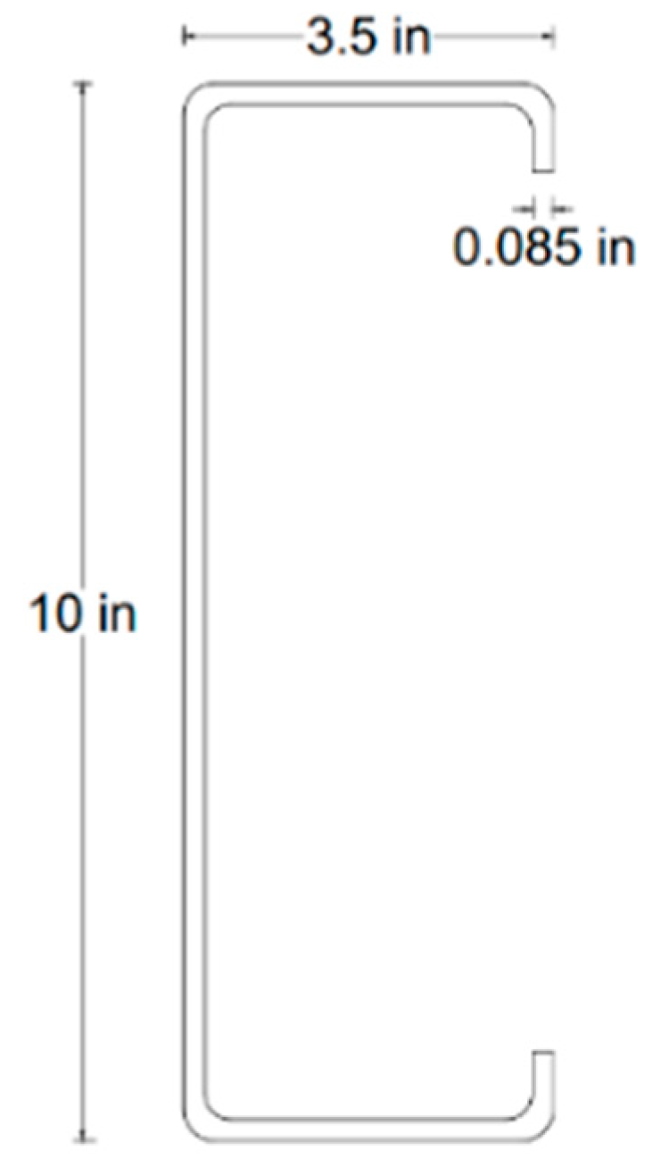
10.1. Example 1: Determining Nominal Axial Strength in Cold-Formed Steel Members

Find ϕ c P n ) for a column which consist of 800S250-68 (see Figure 7), Area = 0.978 in . 2 (630.97 mm 2 ), Depth = 8 in. (203.2 mm), Width = 2.5 in. (63.5 mm), Thickness = 0.0713 in. (1.811 mm), P y = 48.891 Kips (217,478 N), F y = 50 KSi (34,473.8 MPa), and length is 120 inches (3048 mm). according to CUFSM [94]
Solution:
cFSM: P Crl = 12.067 Kips (53,676.7 N), and P Crd = 20.657 Kips (91,886.9 N).
CUFSM: P Crl / P y = 0.24707 (see Figure 8) then P Crl = 0.24707 * 48.891 = 12.079 Kips (53,730.1 N), and P Crd / P y = 0.38614 (see Figure 9) then P Crd = 0.38614 * 48.891 = 18.879 Kips (83,978 N).
When the member is completely braced against GB, strength is controlled by yielding:
Members in Compression:
F n = F y  
  • F n = F y = 50 KSi (34,473.8 MPa).
  • P n e = P y = 48.891 Kips (217,478 N),
  • or
    P n e = F n A g  
Local Buckling:
λ l = P ne / P cr l  
λ l = P ne / P cr l = 48.891 12.079 = 2.012
If λ l 0.776 then
P n l = P ne
but λ l = 2.012 > 0.776
If λ l > 0.776 , then
P n l = 1 0.15 P cr l P ne 0.4 P cr l P ne 0.4 P ne
P n l = 1 0.15 12.079 48.891 0.4 12.079 48.891 0.4 *   48.891 = 25.552 Kips (113,661 N).
  • where: ϕ c = 0.85   ( LRFD ) .
  • ϕ C P n l = 0.85 * 25.552 = 21.719 Kips (96,611 N).
Distortional Buckling:
λ d = P y / P crd  
λ d = P y / P crd = 48.891 18.879 = 1.609
If λ d 0.561 , then
P nd = P y  
but λ d = 1.609 > 0.561
When λ d > 0.561 , then
P nd = 1 0.25 P crd P y 0.6 P crd P y 0.6 P y
P nd = 1 0.25 18.879 48.891 0.6 18.879 48.891 0.6 *   48.891 = 23.722 Kips (105,521 N).
ϕ C P nd = 0.85 * 23.722 = 20.163 Kips (89,689.5 N).
ϕ C P n is the minimum of ( ϕ C P n l = 21.719 Kips (96,611 N), ϕ C P nd = 20.163 Kips (89,689.5 N)).
Distortional Buckling controls the member, then ϕ C P n = 20.163 Kips (89,689.5 N).
But when the member does not brace against global buckling, then:
Abaqus: P Cre = 14.998 Kips (66,714.4 N), P Crl = 11.938 Kips (53,103 N), and P Crd = 18.052 Kips (80,299.3 N).
Members in Compression
Global Buckling:
F cre   = P cre A g  
F cre   = P cre A g = 14.998 0.978 = 15.335 Ksi (105.73 Mpa).
λ c = F y F cre    
λ c = F y F cre   = 50 15.335 = 0.571
If λ c > 1.5   then
F n = 0.877 λ c 2 F y  
but λ c = 0.571 1.5
If λ c 1.5 then,
F n = 0.658 λ c 2 F y  
  • F n = 0.658 0.571 2 * 50 = 43.622 Ksi (300.76 Mpa)
  • P ne   = A g F n = 0.978 * 43.622 = 42.662 Kips (189,770 N).
  • ϕ C P n e = 0.85 * 42.662 = 36.263 Kips (161,305.9 N)
Local Buckling:
  • λ l = P ne / P cr l = 42.662 11.938 = 1.89
  • If λ l 0.776 then P n l = P ne , but λ l = 1.89 > 0.776
  • If λ l > 0.776 , then P n l = 1 0.15 P cr l P ne 0.4 P cr l P ne 0.4 P ne
  • P n l = 1 0.15 11.938 42.662 0.4 11.938 42.662 0.4 *   42.662   = 23.323 Kips (103,745.9 N)
  • where: ϕ c = 0.85   ( LRFD ) .
  • ϕ C P n l = 0.85 * 23.323= 19.824 Kips (88,181.6 N)
Distortional Buckling:
  • λ d = P y / P crd = 48.891 18.052 = 1.645
  • If λ d 0.561 , then P nd = P y , but λ d = 1.645 > 0.561
  • When λ d > 0.561 , then P nd = 1 0.25 P crd P y 0.6 P crd P y 0.6 P y
  • P nd = 1 0.25 18.052 48.891 0.6 18.052 48.891 0.6 *   48.891 = 23.193 Kips (103,167.6 N)
  • ϕ C P nd = 0.85 * 23.193 = 19.714 Kips (87,692.2 N).
  • ϕ C P n is the minimum of ( ϕ C P ne = 36.263 Kips (161,305.9 N), ϕ C P n l = 19.824 Kips (88,181.6 N), ϕ C P nd = 19.714 Kips (87,692.2 N)).
  • Distortional Buckling controls the member, then ϕ C P n = 19.714 Kips (87,692.2 N).
The result of the column shows in Table 1.

10.2. Example 2: Calculating Nominal Flexural Strength in Cold-Formed Steel Elements

Find ( ϕ b M n ) for a beam which consist of 10 C3.5 * 0.85 (see Figure 10), Area = 1.52 in . 2 (980.64 mm . 2 ), Depth = 10 in. (254 mm.), Width = 3.5 in. (88.9 mm.), Thickness = 0.085 in. (2.159 mm.), M y = 256.576 Kips*in. (28,989,195.5 N*mm), F y = 55 Ksi (379.2 Mpa), and length is 200 inches (5080 mm).
Solution:
cFSM: M Crl = 267.690 Kips*in. (30,244,909 N*mm), and M Crd = 221.168 Kips*in (24,988,629 N*mm)
CUFSM: M Crl / M Y = 1.0438 (see Figure 11) then M Crl = 1.0438 * 256.576 = 267.814 Kips*in. (30,258,919 N*mm), and M Crd / M Y = 0.86394 (see Figure 12) then M Crd = 0.86394 * 256.576 = 221.667 Kips*in (25,045,008 N*mm).
When the member is completely braced against GB, strength is controlled by yielding:
Members in Flexure
  • F n = F y = 55 Ksi (379.2 Mpa).
  • P ne = P y = 48.891 Kips (217,478 N), or P ne = F n A g
  • M ¯ ne   = M y = 256.576 Kips*in. (28,989,195.5 N*mm),
  • or
    M ¯ ne   = F n S x  
Local Buckling:
λ l = M ¯ ne   M crl  
λ l = M ¯ ne   / M crl = 256.576 267.814 = 0.979
For λ l 0.776 , then
M n l = M ne  
but λ l = 0.979 > 0.776
When λ l > 0.776 ,
M n l = 1 0.15 M cr l M ¯ ne 0.4 M cr l M ¯ ne 0.4 M ¯ ne
  • M n l = 1 0.15 267.814 256.576 0.4 267.814 256.576 0.4 * 256.576 = 221.184 Kips*in (24,990,436.42 N*mm)
  • Where: ϕ b = 0.90   ( LRFD ) .
  • ϕ b M n l = 0.90 * 221.184 = 199.066 Kips*in (22,491,392 N*mm).
Distortional Buckling
λ d = M y / M crd  
λ d = M y / M crd = 256.576 221.667 = 1.076
If λ d   0.673 , then
M nd = M y  
but λ d = 1.082 > 0.673
When λ d > 0.673,
M nd = 1 0.22 M crd M y 0.5 M crd M y 0.5 M y  
M nd = 1 0.22 221.667 256.576 0.5 221.667 256.576 0.5 *   256.576 = 189.717 Kips*in (21,435,142.81 N*mm).
ϕ b M nd = 0.90 * 189.717 = 170.745 Kips*in (19,291,628 N*mm)
ϕ b M n is the minimum of ( ϕ b M n l = 199.066 Kips*in (22,491,392 N*mm), ϕ b M nd = 170.745 Kips*in (19,291,628 N*mm)).
Distortional Buckling controls the member, then ϕ b M n = 170.745 Kips*in (19,291,628 N*mm).
But when the member does not brace against global buckling, then:
Abaqus: M Cre = 171.43 Kips*in (19,368,989.24 N*mm), M Crl = 269.670 Kips*in (30,468,618.85 N*mm), and M Crd = 219.230 Kips*in (24,769,664,07 N*mm)
Members in Flexure
Global Buckling
F cre   = M cre S x  
F cre   = M cre S x = 171.43 4.63 = 37.026 Ksi (255.29 Mpa).
M y = S f F y  
M y = S f F y = 4.63 * 55 = 254.65 Kips*in (28,771,158.671 N*mm)
If F cre   2.78   F y = 2.78 * 55=152.90 Ksi (1054 Mpa), then
F n = F y  
If F cre   0.56   F y = 0.56 * 55 = 30.80 Ksi (212.4 Mpa), then
F n = F cre  
For 2.78   F y = 2.78 * 55 = 152.90   Ksi   1054   Mpa > F cre   = 37.026   Ksi   255.29   Mpa > 0.56   F y = 0.56 * 55 = 30.80   Ksi   212.4   Mpa , then
F n = 10 9   F y 1 10   F y 36   F cre    
F n = 10 9 * 55 1 10 * 55 36   *   37 . 026 = 35.895 Ksi (247.5 Mpa)
M ne = S fc F n M y
  • M ne = 4.63 * 35.895 = 166.194   Kips * in   187 , 774 , 001   N * mm M y = 254.65 Kips*in (28,771,587 N*mm)
  • ϕ b M ne = 0.90 * 166.194= 149.575 Kips * in (16,899,706 N*mm)
  • M ¯ ne   = M ne = 166.194   Kips * in   187 , 774 , 001   N * mm .
Local Buckling:
  • λ l = M ¯ ne   / M crl = 166.194 269.670 = 0.785
  • For λ l 0.776 , then M n l = M ne   , but λ l = 0.785 > 0.776
  • When λ l > 0.776 , M n l = 1 0.15 M cr l M ¯ ne 0.4 M cr l M ¯ ne 0.4 M ¯ ne
  • M n l = 1 0.15 269.670 166.194 0.4 269.670 166.194 0.4 * 166.194   = 164.980 Kips*in (18,640,237 N*mm)
  • Where: ϕ b = 0.90   ( LRFD ) .
  • ϕ b M n l = 0.90 * 164.980 = 148.482 Kips*in (16,776,213.4 N*mm)
Distortional Buckling
  • λ d = M y / M crd = 254.65 219.230 = 1.078
  • If λ d   0.673 , then M nd = M y , but λ d = 1.078 > 0.673
  • When λ d > 0.673, M nd = 1 0.22 M crd M y 0.5 M crd M y 0.5 M y
  • M nd = 1 0.22 219.230 254.65 0.5 219.230 254.65 0.5 *   254.65 = 188.047 Kips*in (21,246,458.2 N*mm).
  • ϕ b M nd = 0.90 * 188.047 = 169.242 Kips*in (19,121,778.4 N*mm)
  • ϕ b M n is the minimum of ( ϕ b M ne = 149.575 Kips * in (16,899,706 N*mm), ϕ b M n l = 148.482 Kips*in (16,776,213.4 N*mm), ϕ b M nd = 169.242 Kips*in (19,121,778.4 N*mm)).
  • Local Buckling controls the member, then ϕ b M n = 148.482 Kips*in (16,776,213.4 N*mm).
The result of the beam shows in Table 2.

11. Discussion of Findings and Results

The numerous aspects that impact the design and analysis of CFS built-up members are thoroughly discussed in this review study, with a specific emphasis on columns and beams. The paper explores the impact of partial composite action, fastener spacing, and bolt arrangement on the strength and behavior of these structures, and proposes different formulas and approaches for accurately estimating built-up sections’ critical buckling load and strength. The discussion also covers the failure modes of these columns, including interaction buckling, LB, GB, and DB, and highlights the importance of factors such as web aperture, stiffeners, connection spacing, lipped U-sections, and screw spacing in the behavior of CFS sections.
The study investigated the structural behavior of beams and columns composed of single U-sections, employing two distinct software packages, namely ABAQUS and CUFSM. Several critical parameters were derived, including the Critical Elastic Local Column Buckling Load ( P crl ), Critical Elastic Distortional Column Buckling Load ( P crd ), Critical Elastic Global Column Buckling Load ( P cre ), Critical Elastic Local Beam Buckling Moment ( M crl ), Critical Elastic Distortional Beam Buckling Moment ( M crd ), and Critical Elastic Global Beam Buckling Moment ( M cre ).
In addition, the American Iron and Steel Institute (AISI) standard [7,8] was employed to determine key values, including the Nominal Axial Strength for Local Buckling ( P nl ), Nominal Axial Strength for Distortional Buckling ( P nd ), Nominal Axial Strength for Global Buckling ( P ne ), and the Available Axial Strength ( ϕ C P n ) for columns. Likewise, the Nominal Flexural Strength for Local Buckling ( M nl ), Nominal Flexural Strength for Distortional Buckling ( M nd ), Nominal Flexural Strength for Global Buckling ( M ne ), and the Available Flexural Strength ( ϕ b M n ) for beams were computed.
Upon careful analysis and comparison of these results, it was observed that CUFSM exhibited limitations in accurately predicting the Critical Elastic Global Column Buckling Load ( P cre ) and the Critical Elastic Global Beam Buckling Moment ( M cre ). Consequently, the assumption was made that the beams and columns can be considered fully braced against global buckling. Subsequent comparison between the results obtained from ABAQUS and CUFSM indicated notable discrepancies, with CUFSM yielding results differing by 10.171% for columns and 14.994% for beams when compared to ABAQUS.
These disparities between the software outputs underscore the challenge of relying on CUFSM for research purposes. It is hypothesized that the variation in results stems from the distinct methodologies employed by each software, with one utilizing Finite Element Method (FEM) and the other employing Finite Strip Method (FSM). This discrepancy highlights the importance of selecting appropriate software tools in structural analysis to ensure the accuracy and reliability of research outcomes.

12. Conclusions and Key Takeaways from the Study

In conclusion, this state-of-the-art review paper has undertaken a comprehensive exploration of the design and analysis of cold-formed steel (CFS) elements, with a particular emphasis on columns and beams. The literature review looked at many things that affect how CFS structures behave and work, such as partial composite action, fastener spacing, bolt arrangement, web aperture, stiffeners, and connection spacing. Additionally, the paper delved into the implications of temperature variations on the mechanical attributes and functionality of CFS sections.
From the detailed analysis of the literature, it is clear that accurate estimation of critical buckling loads and moment resistance is key to making sure that CFS components are safe and work well. In the paper, different formulations and methods were suggested to reach this goal, taking into account different types of buckling, such as global, local, and distortional buckling.
Nonetheless, despite recognizing the substantial impact of the aforementioned factors on beams and columns, the precise magnitude of their influence remains elusive. This knowledge gap signifies fertile ground for further research and investigation. Also, it was noticed that the current standards and codes, like AISI S100-16 [7,8], AISI-D100-08 [5], AISI-S240-20 [10], AS/NZS 4600-2018 [9], and Eurocode 3 (part-1-3) [4], do not say enough about how screws are used to connect CFS sections, especially in terms of screw spacing, screw diameter, and multiple screw rows. Consequently, a call for revising these regulations to offer more pragmatic guidelines to designers and engineers is warranted. As a suggestion to fellow researchers, the development of equations to quantify the strength variation arising from changes in connector diameter and spacing is proposed.
The comparative analysis of results obtained through CUFSM and ABAQUS software tools revealed significant disparities. These differences, which show that CUFSM is off by 10.171% for columns and 14.994% for beams compared to ABAQUS, show how hard it is to do research using only CUFSM. It is postulated that these variations stem from the distinct methodologies employed by each software, with FEM and FSM driving the disparity.
In its entirety, this state-of-the-art review paper stands as an invaluable resource, serving as a bridge between researchers and practitioners in the field of structural engineering. The insights and recommendations presented herein will facilitate the efficient and secure design and analysis of CFS elements, contributing to advancements in the field and the widespread adoption of CFS in various construction projects globally.

Author Contributions

Conceptualization, A.B.H. and F.P.: A.B.H. initiated the research and received guidance from F.P. in conceptualizing the study. Methodology, A.B.H.: A.B.H. designed the research methodology. Software, A.B.H.: A.B.H. utilized ABAQUS and CUFSM for the computational aspects of the research. Validation, A.B.H. and F.P.: A.B.H. and F.P. jointly conducted validation procedures to ensure research accuracy. All authors have read and agreed to the published version of the manuscript.

Funding

Széchenyi István University Publication Support Program; Identification number (Reference no): 082PTP2023; Financial Center: NPSZ00300T; Functional Area: NP10000.

Conflicts of Interest

The authors declare no conflict of interest related to this research manuscript. We have no financial, personal, or professional interests that could influence the research, analysis, or interpretation presented in this paper. We affirm that the research and the writing process have been conducted with the utmost integrity and adherence to ethical standards.

Nomenclature

SymbolsDefinitions
LBLocal buckling
DBDistortional buckling
FB Flexural buckling
FT Flexural-Tortional buckling
DL Distortional-Lateral buckling
LF Lateral-Flexural buckling
DF Distortional-Flexural buckling
FTL Flexural-Tortional + Lateral buckling
FTD Flexural-Tortional + Distortional buckling
FFT Flexural + Flexural-Tortional buckling
A 0 ,   A g cross-sectional area in gross
A f area of the flange
A h area of the hole
A s the opening’s area
A w area of the web
b rectangular opening’s horizontal dimension
C w , net the net member’s warping stiffness
dthe diameter of a round hole or the size of a square hole
EYoung’s elasticity modulus
EI web web’s flexural stiffness
GJ f the flange’s rectangular opening’s torsional stiffness
hthe web’s flat depth
h s depth of the web stiffener
I g the gross cross-section’s moment of inertia
I net net cross-sectional moment of inertia at a hole
J avg the torsional constant of St. Venant, includes the effect of openings
k 0 coefficient of shear buckling of the section without the opening
k v coefficient of shear buckling of the section with the opening
Lspan or length of the section ( L g + L net )
L g length of the column member with no openings
L net length of the column part with openings
L cre Global Buckling’s (GB) Half-Wavelength
L crd Distortional Buckling’s (DB) Half-Wavelength
L crl Local Buckling’s (LB) Half-Wavelength
M crd DB’s critical elastic moment
M crd h DB’s critical elastic moment with holes’ impact
M crd nh DB’s critical elastic moment with no holes’ impact
M cre h LTB’s critical elastic moment with openings’ impact
M cre   LTB’s Critical elastic moment
M crl h LB’s critical elastic moment with openings’ impact
M crl nh , M crl LB’s critical elastic moment with no openings’ impact
M nd DB’s nominal flexural strength
M ne LTB’s nominal flexural strength
M ¯ ne minimum   of   M cr l ,   and   M ne     and   M y is the LB’s Critical elastic moment
M nl LB’s nominal flexural strength
M pv the bottom or top segment below or above the holes’ (with the lips and the flanges) plastic flexure moment capability
M p Member plastic moment
M u , M n nominal flexural strength
M y member   yield   moment . ( S g F y )
M ¯ X , M ¯ y Positive flexural strengths are required
M ax ,   M ay flexural strengths that are available around centroidal axes
M ax l o , M ay l o The flexural strengths pertaining to centroidal axis that are currently accessible with F n = F y or M ne = M y
B ¯ Required bimoment strength [bimoment due to factored loads] taken as positive
B a available bimoment strength [factored resistance]
s max the greatest longitudinal fastener spacing
M yn   Moment of yielding for net cross-sectional
Z f Plastic section modulus
S fc Modulus of elasticity of the whole, unreduced fiber segment under very high compression
S f Full unreduced cross-sectional elastic modulus in relation to the extreme fiber in the initial yield
F y yielding stress
F n Compressive stress
F cre   Elastic global (FTB, or TB, FB) stress
Nbearing plate’s length
nthe load (support) plate’s effective length
P crd Column force critical for elastic DB
P crd h DB’s critical elastic load for a section with opening
P crd nh DB’s critical elastic load for a section with no opening
P cre h GB’s critical elastic load for a section with opening
P cre GB’s critical elastic load of the column
P crl LB’s critical elastic load of the column
P crl h LB’s critical elastic load for a section with opening
P crl nh LB’s critical elastic load for a section with no opening
P MS Theoretical estimates of web-holed section compression resistance [95]
P nd DB’s nominal axial strength
P ne GB’s nominal axial strength
P nle , P n l LB’s nominal axial strength
P prop ,   P ult the section’s compression resistance with web opening
P ¯ axial compressive strength measured in a positive direction
P n Nominal Axial Strength
P a axial strength available
P y member   Axial   Yield   Strength   ( A g F y )
P yn   net cross-section’s yield strength
q the web hole’s edge-stiffener’s length
q s factor for reducing shear strength
R p proposed reduction factor for web crippling strength
r q The inner corner radius refers to the curvature between the web and the edge-stiffener of an opening
S spacing of the opening
sclear spacing of the opening
tthickness of the web
t equ thickness equivalence
t f thickness of the flange
V 1 , V 2 The shear forces acting at each opening’s edge
V n a web’s nominal resistance to shear [96,97]
V nl The shear capacity of a section is diminished when it has an opening.
V v element’s shear capability with no opening
V vrd shear that was performed over the hole using the Vierendel mechanism
V vrd , 0.6 shear that was performed over the hole using the Vierendel mechanism for the member characterized by the ratio of hole diameter (d) to section height (h) equal to 0.6.
V vrd , m shear that was performed over the hole using the Vierendel mechanism for the member characterized by the ratio of dh/h equal to m.
V y The shear load capacity for the section with no openings.
V yh The shear load capacity for the section with openings.
x The horizontal clear space between the web openings and the edge of the bearing plate.
gThe vertical distance refers to the measurement between two rows of connectors that are located closest to the top and bottom flanges.
T s connection’s available tension strength
mThe measurement of the distance between the shear center of a C-section and the mid-plane of its web.
qDetermine the longitudinal spacing of fastener based on the intended load on the beam.
I r reduced moment of inertia in determining the global buckling force
Ithe built-up component’s Moment of inertia around the flexural buckling axis
KLThe length of the built-up part that is effective for the axis of the flexural buckling
rThe radius of gyration of the built-up member’s complete unreduced cross-sectional area around the axis of flexural buckling.
aspacing between sections for shear-bearing welds or intermediate fasteners
r i Minimum radius of gyration of an individual shape’s complete unreduced cross-sectional area in a built-up member
M a l 0 Flexural strength that is available for a built-up part around the axis of buckling with F n   = F y   or   M ne   = M y
QFor the gross built-up cross-section, the initial moment of area of linked shapes around the buckling axis
I g Gross built-up cross-section moment of inertia around the buckling axis

Appendix A

Table A1. Pure compression design equations [2].
ReferencesRulesComments
[7] P ne   = A g F n
λ c = F y F cre  
where   λ c 1.50 ,   F n = 0.6580 λ c 2 * F y
where   λ c > 1.50 ,   F n = 0.8770 λ c 2 * F y
Yielding and Global (FB, TB, or FTB)
λ l = P ne P cr l
where   λ l 0.7760 ,   P n l = P ne
where λ l > 0.7760 ,   P n l = 1.0 0.150 P cr l P ne 0.40 P cr l P ne 0.40 * P ne
Yielding and Global Buckling Interacting with LB
λ d = P y P crd
where   λ d   0.5610 ,   P nd = P y
where λ d > 0.5610 ,   P nd = 1.0 0.250 P crd P y 0.60 P crd P y 0.60 * P y
Distortional Buckling
[98] P ult P y = k 1 A 0 A 1 + k 2 A 0 A 1 0.5 + k 3
k 1 = 1.1850   m 3 3.8487   m 2 + 3.7321   m 1.23360
k 2 = 0.1111   m 2 + 0.0932   m 0.77630
k 3 = 0.11   m 2 0.5681   m + 1.14120
m = 1 100 h t
[95] P ne = 0.658 λ c 2 P y ,   for   λ c 1.5
P ne = 0.877 λ c 2 P y , ,   for   λ c > 1.5
λ c = P y P cre h
(F, T, or FT) buckling
P nle = P ne P yn ,   where   λ le 0.776
P nle = 1 0.15 P crl h P ne 0.4 P crl h P ne 0.4 P ne P yn ,   for   λ le > 0.776
λ le = P ne P crl h
LB
P nd = P yn ,   for   λ d λ d 1
P nd = P yn P yn P d 2 λ d 2 λ d 1 λ d λ d 1 ,   for   λ d 1 < λ d λ d 2
P nd = 1 0.25 P crd h P y 0.6 P crd h P y 0.6 P y ,   for   λ d > λ d 2
λ d = P y P crd h , λ d 1 = 0.561 P yn P y , λ d 2 = 0.561 14 P y P yn 0.4 13
P d 2 = 1 0.25 1 λ d 2 1.2 1 λ d 2 1.2 P y
distortional buckling
[99] P ne = 0.658 λ c 2 P y ,   for   λ c 1.50
P ne = 0.877 λ c 2 P y ,   for   λ c > 1.50
λ c = P y P cre h
(F, T, or FT) buckling
P nle = P ne P yn ,   for   λ le 0.776
P nle = 1 0.15 P crl nh P ne 0.4 P crl nh P ne 0.4 P ne P yn ,   for   λ le > 0.776
λ le = P ne P crl nh
local buckling
P nd = P min ,   for   λ d λ d 1
P nd = P min P min P d 2 λ d 2 λ d 1 λ d λ d 1 ,   for   λ d 1 λ d λ d 2
P nd = 1 0.25 P crd nh P ne 0.6 P crd nh P ne 0.6 P ne ,   for   λ d > λ d 2
λ d = P ne P crd nh , λ d 1 = 0.561 P yn P y , λ d 2 = 0.561 14 P y P yn 0.4 13
P d 2 = 1 0.25 1 λ d 2 1.2 1 λ d 2 1.2 P ne , P min = min P ne , P yn
distortional buckling
[100] P prop   = 1.92 q s 0.047 r q s 0.017 P MS ,   for   0.28 b < λ c < 0.77 b
P prop   = 1.95 q s 0.034 r q s 0.022 P MS ,   for   0.77 b < λ c < 1.71 b
P prop   = 1.91 q s 0.038 r q s 0.021 P MS ,   for   1.71 b < λ c < 2.68 b
λ c = P y P cre   h
[101] P cre h = π 2 E L 2 I g L g + I net L net L global flexural buckling
P cre h = A 0 2 β σ ex + σ t σ ex + σ t 2 4 β σ ex σ t flexural–torsional buckling
P crd = min P crd nh , P crd h distortional buckling
P crl = min P crl nh , P crl h local buckling
Table A2. Equations for flexure design [2].
ReferencesRulesComments
[7] M ne = S fc F n M y
M y = S f F y
Where: F cre   2.780   *   F y , F n =   F y
where: 2.78 0   *   F y >   F cre   > 0.560   *   F y , F n = 10 9 * F y * 1.0 10   F y 36   F cre  
where: F cre   0.560   *   F y , F n = F cre  
Yielding and Global (LTB).
Capability till the first yield
For M cre   > 2.78 M y ; M ne   = M p M p M y M y / M cre   0.23 0.37 M p
M p   = Z f F y
Yielding and Global (LTB).
Reserve capacity that is inelastic.
λ l = M ¯ ne   / M crl
Where: λ l 0.7760 , M n l = M ne  
Where: λ l > 0.7760 , M n l = 1.0 0.150 M cr l   M   ¯ ne 0.40 M cr l   M   ¯ ne 0.40   *   M ¯ ne
LB Interacting with GB.
λ d = M y / M crd
Where: λ d   0.673 0, M nd = M y
Where: λ d > 0.6730, M nd = 1.0 0.220 M crd M y 0.50 M crd M y 0.50   *   M y
Distortional Buckling
[23] M nl = M yn ,   for   λ l 0.936
M nl = 1 0.04 M cr h M y 0.32 M crl h M y 0.32 M y M yn ,   for   λ l > 0.936
λ l = M y M crl h
built-up sections, local buckling
[102] M nl = M yn ,   for   λ l λ a
M nl = α 1 0.15 M crl h M ne 0.4 β M cr h M ne 0.4 β M ne M yn ,   for   λ l > λ a
α = M yn M y 19.4 M yn M y 14.8 , β = M yn M y 2.1 , λ l = M y M crl h , α 1 0.15 λ 0 0.8 β λ a 0.8 β = M yn M y
local buckling
M nd = M yn ,   for   λ d λ d 1
M nd = M yn M yn M d 2 λ d 2 λ d 1 λ d λ d 1 0.88 1 0.2 M crd h M y 0.45 M crd h M y 0.45 M y   ;   for   λ d 1 < λ d λ d 2
M nd = 0.88 1 0.2 M crd h M y 0.45 M crd h M y 0.45 M y   ;   for   λ d > λ d 2
λ d = M y M crd h , λ d 1 = 0.538 M yn M y 3 , λ d 2 = 0.538 1.7 M y M yn 2.7 0.7 ;
M d 2 = 0.88 1 0.2 1 λ d 2 0.9 1 λ d 2 0.9 M y
distortional buckling
[101] M cre h = π L EI y , avg GJ avg + EC w , net π 2 L 2 lateral–torsional buckling
M crd = min M crd nh , M crd h distortional buckling
[103] M nl = M y ,   for   λ l 0.925
M nl = 1 0.05 M crl nh M y 0.35 M cr nh M y 0.35 M y ,   for   λ l > 0.925
λ l = M y M crl nh
local buckling
Table A3. Web crippling rules [2].
ReferencesRulesComments
[104] :   R p = 1.0 0.60 * d h ,   where :   0.0 < d h 0.50
:   R p = 1.0 0.770 * d h ,   where :   0.0 < d h 0.642
ITF
[105] :   R p = 1.040 0.680 * d h + 0.0230 * x h 1.0
:   R p = 1.0 0.450 * d h + 0.090 * x h 1.0
ITF
[106] :   R p = 1.050 0.540 * d h + 0.010 * N h 1.0
:   R p = 1.010 0.510 * d h + 0.060 * N h 1 .0
ITF
[107]❺:(ITF)
:   R p = 0.980 0.650 * d h + 0.070 * N h 1.0
:   R p = 0.990 0.040 * d h + 0.030 * N h 1.0
❻:
:   R p = 0.940 0.620 * d h + 0.210 * x h 1.0
:   R p = 0.940 0.480 * d h + 0.260 * x h 1.0
[108] :   R p = 1.020 0.390 * d h + 0.020 * N h + 0.040 * r q t + 0.490 * q h 1.0
:   R p = 1.010 0.160 * d h + 0.060 * x h + 0.040 * r q t + 0.310 * q h 1.0
ITF, edge–stiffened holes
[109] R p = 1 0.197 d h 2 1 0.127 b n 2 IOF
[110] R p = 0.964 0.272 d h + 0.0631 α 1
α 4.31 d h + 0.571 0
IOF
[110]❺:IOF
❸: R p = 0.980 0.260 * d h + 0.060 * N h 1.0
❹: R p = 0.950 0.060 * d h + 0.010 * N h 1.0
❻:
❸: R p = 0.990 0.260 * d h + 0.110 * x h 1.0
❹: R p = 0.990 0.140 * d h + 0.070 * x h 1.0
[110] R p = 1.08 0.63 d h + 0.12 α 1
  α 5.25 d h + 0.67 0
EOF
[111]❺:EOF
:   R p = 0.960 0.340 * d h + 0.090 * N h 1.0
:   R p = 0.930 0.410 * d h + 0.160 * N h 1.0
❻:
:   R p = 0.970 0.260 * d h + 0.140 * x h 1.0
:   R p = 0.970 0.140 * d h + 0.070 * x h 1.0
[106] :   R p = 0.900 0.600 * d h + 0.120 * N h 1.0
:   R p = 0.950 0.500 * d h + 0.080 * N h 1.0
ETF
[112] :   R p = 0.950 0.490 * d h + 0.170 * x h 1.0
:   R p = 0.960 0.360 * d h + 0.140 * x h 1.0
ETF
[113] :   R p = 0.920 0.350 * d h + 0.120 * N h + 0.210 * r q t + 0.220 * q h 1.0
:   R p = 0.980 0.110 * d h + 0.010 * x h + 0.050 * r q t + 0.410 * q h 1.0
ETF, openings with stiffening edges
❶: Circular holes. ❷: Square holes. ❸: Unfastened flanges. ❹: Fastened flanges. ❺: Centered web holes. ❻: Offset web holes.
Table A4. Formulas for shear [2].
ReferencesRulesComments
[27] V nl = q s 1 q s 2 V n
q s 1 = 1 54 c 1 t   ;   for   5 c 1 t 54
q s 1 = 1   ;   for   c 1 t > 54
q s 2 = 1.5 V 1 V 2 0.5 1.3   ;   for   c 1 t 54
q s 2 = 1   ;   for   c 1 t > 54
Circular holes: c 1 = h 2 d 2.83
Square holes: c 1 = h 2 d 2
[114]circular holes:
k v = k 0 1 0.5 * d L 4.2 * d L 2 ,   for   d L 0.2
k v = k 0 1.150 2.350 * d L + 1.50 * d L 2 ,   where :   0.2 < d L 0.6
k v = k 0 0.6 0.53 d L ,   for   d L 0.6
square holes:
k v = k 0 1 0.8 d L 4.5 d L 2 ,   for   d L 0.2
k v = k 0 1.15 2.95 d L + 2.2 d L 2 ,   for   0.2 < d L 0.6
k v = k 0 0.4 0.33 d L ,   for   d L 0.6
k 0 = 5.34 + 4 L h 2
[115]option 1:
V nl = q s V v
q s = 1 0.6 d h ,   for   0 < d h 0.3
q s = 1.215 1.316 d h ,   for   0.3 < d h 0.7
q s = 0.732 0.625 d h ,   for   0.7 < d h 0.85
option 2:
q s = 1 0.6 d h ,   for   0 < d h 0.3
q s = 1.224 1.346 d h ,   for   0.3 < d h 0.85
[116] V yh = V y ,   for   0 < d h 0.1
V yh = V y 2 d h 0.1 V y V vrd , 0.6 ,   for   0.1 < d h < 0.6
V yh = V vrd ,   for   d h 0.6
V vrd = 4 M pv b
[117] V yh = 0.6 A w f y = V y ,   for   0 < d h 0.1
V yh = V y 1 m 0.1 d h 0.1 V y V vrd , m v i ,   for   0.1 < d h < m
V yh = V vrd v i ,   for   d h m
m = 0.715 0.125 b d + 0.01 b d 2 ,
v i = 0.745 + 0.28 b d 0.025 b d 2
[118] k v = k 0 1.0 0.80 * d L 4.50 * d L 2 ;   where :   d L 0.20
k v = k 0 1.15 2.95 * d L + 2.2 * d L 2 ;   where :   0.2 < d L 0.6
k v = k 0 0.4 0.33 d L ;   where :   d L 0.6
V yh = 0.6 d 1 d t f y

References

  1. Yu, W.-W. Scholars’ Mine Scholars’ Mine AISI-Specifications for the Design of Cold-Formed Steel Structural Members. 2009. Available online: https://scholarsmine.mst.edu/ccfss-aisi-spechttps://scholarsmine.mst.edu/ccfss-aisi-spec/159 (accessed on 9 August 2023).
  2. Živaljević, V.; Jovanović, Đ.; Kovačević, D.; Džolev, I. The Influence of Web Holes on the Behaviour of Cold-Formed Steel Members: A Review. Buildings 2022, 12, 1091. [Google Scholar] [CrossRef]
  3. Yu, W.-W.; LaBoube, R.A.; Chen, H. Cold-Formed Steel Design, 5th ed.; John Wiley & Sons: Hoboken, NJ, USA, 2020. [Google Scholar]
  4. Dubina, D.; Ungureanu, V.; Landolfo, R. Eurocode 3: Part 1-3, 1st ed.; ECCS—European Convention for Constructional Steelwork: Brussels, Belgium, 2012. [Google Scholar]
  5. Manual, A. AISI D100-08. 2008. Available online: https://scholarsmine.mst.edu/ccfss-aisi-spec/159/ (accessed on 9 August 2023).
  6. ANSI/AISC 360-22; Specification for Structural Steel Buildings. AISC: Chicago, IL, USA, 2022.
  7. AISI S100-16 (R2020) w/S3-22; North American Specification for the Design of Cold-Formed Steel Structural Members. AISI: Washington, DC, USA, 2016; Volume 3.
  8. AISI S100-16 (2020) w/S2-20; North American Specification for the Design of Cold-Formed Steel Structural Members. AISI: Washington, DC, USA, 2016; Volume 2.
  9. AS/NZS 4600:2018; Cold-Formed Steel Structures. Standards New Zealand: Wellington, New Zealand, 2018. Available online: www.standards.govt.nz (accessed on 9 August 2023).
  10. AISI S240-20; North American Standard for Cold-Formed Steel Structural Framing. AISI: Washington, DC, USA, 2020.
  11. Dubina, D. Chapter 2: Peculiar Problems in Cold-formed Steel Design Parti 2.1 Elements 2.2.1. Cold-formed steel sections: Linear profiles, cladding and sheeting panels. In Light Gauge Metal Structures Recent Advances; Springer: Berlin/Heidelberg, Germany, 2007. [Google Scholar]
  12. Beulah, G.; Ananthi, G. State-of-the-Art Review on Cold-Formed Steel Channel Sections under Compression. J. Struct. Eng. 2017, 44, 23–38. Available online: https://www.researchgate.net/publication/318261977 (accessed on 9 August 2023).
  13. Lu, Y.; Zhou, T.; Li, W.; Wu, H. Experimental investigation and a novel direct strength method for cold-formed built-up I-section columns. Thin-Walled Struct. 2017, 112, 125–139. [Google Scholar] [CrossRef]
  14. Mathews, D.P.K.M. Web Buckling Analysis of Cold Formed Built-Up I Section. GRD J.-Glob. Res. Dev. J. Eng. 2017, 2, 177–182. Available online: www.grdjournals.com (accessed on 9 August 2023).
  15. Wald, F.; Wald, F.; Jandera, M. Numerical investigation of steel built-up columns composed of track and channel cold-formed sections. In Stability and Ductility of Steel Structures 2019: Proceedings of the International Colloquia on Stability and Ductility of Steel Structures, Prague, Czech Republic, 11–13 September 2019; CRC Press: Boca Raton, FL, USA, 2019; pp. 370–373. Available online: https://www.researchgate.net/publication/336286611_Numerical_Investigation_of_Steel_Built-up_Columns_Composed_of_Track_and_Channel_Cold-Formed_Sections (accessed on 2 June 2023).
  16. Schafer, B.W.; Peköz, T. Computational modeling of cold-formed steel: Characterizing geometric imperfections and residual stresses. J. Constr. Steel Res. 1998, 47, 193–210. [Google Scholar] [CrossRef]
  17. Liao, F.; Wu, H.; Wang, R.; Zhou, T. Compression test and analysis of multi-limbs built-up cold-formed steel stub columns. J. Constr. Steel Res. 2016, 128, 405–415. [Google Scholar] [CrossRef]
  18. Ting, T.C.H.; Roy, K.; Lau, H.H.; Lim, J.B.P. Effect of screw spacing on behavior of axially loaded back-to-back cold-formed steel built-up channel sections. Adv. Struct. Eng. 2017, 21, 474–487. [Google Scholar] [CrossRef]
  19. Post, B. Fastener Spacing Study of Cold-Formed Steel Wall Studs Using Finite Strip and Finite Element Methods; Johns Hopkins University: Baltimore, MD, USA, 2012. [Google Scholar]
  20. Landolfo, R. Material Ductility and Buckling Behaviour of Eurocode-compliant Cold-formed Steel Hollow Columns. ce/papers 2022, 5, 1–8. [Google Scholar] [CrossRef]
  21. Laboube, R.A.; Yu, W.W.; Deshmukh, S.U.; Uphoff, C.A. Crippling capacity of web elements with openings. J. Struct. Eng. 1999, 125, 137–141. [Google Scholar] [CrossRef]
  22. Fang, Z.; Roy, K.; Chen, B.; Xie, Z.; Ingham, J.; Lim, J.B.P. Effect of the web hole size on the axial capacity of back-to-back aluminium alloy channel section columns. Eng. Struct. 2022, 260, 114238. [Google Scholar] [CrossRef]
  23. Wang, L.; Young, B. Design of cold-formed steel built-up sections with web perforations subjected to bending. Thin-Walled Struct. 2017, 120, 458–469. [Google Scholar] [CrossRef]
  24. Hancock, G.J. Cold-formed steel structures. J. Constr. Steel Res. 2003, 59, 473–487. [Google Scholar] [CrossRef]
  25. Young, B.; Hancock, G.J. Design of cold-formed channels subjected to web crippling. J. Struct. Eng. 2001, 127, 1137–1144. [Google Scholar] [CrossRef]
  26. He, J.; Young, B. Web crippling design of cold-formed steel built-up I-sections. Eng. Struct. 2022, 252, 113731. [Google Scholar] [CrossRef]
  27. Matthew, R.; Roger, E.; LaBoube, A.; Yu, W. Behavior of Web Elements with Openings Subjected to Linearly Varying Shear. 1997. Available online: https://scholarsmine.mst.edu/ccfss-libraryhttps://scholarsmine.mst.edu/ccfss-library/149 (accessed on 9 August 2023).
  28. Rasmussen, K.J.R.; Khezri, M.; Schafer, B.W.; Zhang, H. The mechanics of built-up cold-formed steel members. Thin-Walled Struct. 2020, 154, 106756. [Google Scholar] [CrossRef]
  29. von Kármán, T.; Sechler, E.E.; Donnell, L.H. The strength of thin plates in compression. Trans. Am. Soc. Mech. Eng. 1932, 54, 53–56. [Google Scholar] [CrossRef]
  30. Winter, G. Strength of thin steel compression flanges. Trans. Am. Soc. Civ. Eng. 1947, 112, 527–554. [Google Scholar] [CrossRef]
  31. Schafer, B.W. Review: The Direct Strength Method of cold-formed steel member design. J. Constr. Steel Res. 2008, 64, 766–778. [Google Scholar] [CrossRef]
  32. Bhatti; Hamza, A.; Qadeer, J.; Khan, R.M.A.; Khan, M.A. Design of Cold-form Beams Using Effective Width Method and Direct Strength Method: A Comparative Study. Pak. J. Sci. Ind. Res. Ser. A Phys. Sci. 2023, 66, 120–129. [Google Scholar]
  33. Schafer, B.W. Advances in the Direct Strength Method of cold-formed steel design. Thin-Walled Struct. 2019, 140, 533–541. [Google Scholar] [CrossRef]
  34. Camotim, D.; Dinis, P.B.; Martins, A.D. Direct strength method-a general approach for the design of cold-formed steel structures. In Recent Trends in Cold-Formed Steel Construction; Elsevier Inc.: Amsterdam, The Netherlands, 2016; pp. 69–105. [Google Scholar] [CrossRef]
  35. Wang, L.; Young, B. Behaviour and design of cold-formed steel built-up section beams with different screw arrangements. Thin-Walled Struct. 2018, 131, 16–328. [Google Scholar] [CrossRef]
  36. Mahar, A.M.; Jayachandran, S.A.; Mahendran, M. Global buckling strength of discretely fastened back-to-back built-up cold-formed steel columns. J. Constr. Steel Res. 2021, 187, 106998. [Google Scholar] [CrossRef]
  37. Nie, S.F.; Zhou, T.H.; Zhang, Y.; Liu, B. Compressive behavior of built-up closed box section columns consisting of two cold-formed steel channels. Thin-Walled Struct. 2020, 151, 106762. [Google Scholar] [CrossRef]
  38. Ghannam, M. Behaviour of Axially Loaded Cold-Formed Steel Built-Up Stub Columns. In Proceedings of the 1st International Conference on Structural Engineering Research (iCSER 2017), Sydney, Australia, 20–22 November 2017. [Google Scholar]
  39. Fratamico, D.C.; Torabian, S.; Rasmussen, K.J.R.; Schafer, B.W. Buckling and Collapse Behavior of Screw-Fastened, Built-Up Cold-Formed Steel Columns of Varying Cross-Section Size: Experimental Investigation. In Proceedings of the Annual Stability Conference Structural Stability Research Council, San Antonio, TX, USA, 21–24 March 2017; Available online: https://www.aisc.org/globalassets/continuing-education/ssrc-proceedings/2017/buckling-and-collapse-behavior-of-screw-fastened-built-up-cold-formed-steel-columns-of-varying-cross-section-size-experimental-investigation.pdf (accessed on 26 June 2023).
  40. Tawfic, M.; Amoush, E. Compressive Strength of Axially Loaded Built-up Sigma Cold Formed Sections Columns. Future Eng. J. 2020, 1, 2314–7237. Available online: https://digitalcommons.aaru.edu.jo/fej/vol1/iss1/6/ (accessed on 27 July 2023).
  41. Samuel, J.; Joanna, P.S. Experimental Study and Numerical Modelling on the Behaviour of Built-Up Cold-Formed Steel Beams with Diagonal Web Bars. Int. J. Sci. Technol. Res. 2020, 9, 2. Available online: www.ijstr.org (accessed on 27 July 2023).
  42. Meza, F.J.; Becque, J.; Hajirasouliha, I. Experimental study of cold-formed steel built-up columns. Thin-Walled Struct. 2020, 149, 106291. [Google Scholar] [CrossRef]
  43. Vishweswaran, C.K.; Srisanthi, V.G. Experimental Study on Cold-formed Steel Built-up Column Sections. Int. J. Innov. Res. Technol. 2021, 8, 152058. [Google Scholar]
  44. Fratamico, D.C.; Torabian, S.; Zhao, X.; Rasmussen, K.J.R.; Schafer, B.W. Experimental study on the composite action in sheathed and bare built-up cold-formed steel columns. Thin-Walled Struct. 2018, 127, 290–305. [Google Scholar] [CrossRef]
  45. Lukačević, I.; Ungureanu, V. Numerical parametric study on corrugated web built-up beams with pinned end supports. In Proceedings of the Cold-Formed Steel Research Consortium Colloquium, Online, 17–19 October 2022; Available online: https://www.researchgate.net/publication/364403581 (accessed on 9 August 2023).
  46. Mon, T.Y.; Selvam, J. Buckling Behaviors of Cold-Formed Steel Built-Up Columns under Axial Compression Tests: Review Paper. Int. J. Recent Technol. Eng. 2021, 10, 7–11. [Google Scholar] [CrossRef]
  47. Fratamico, D.C.; Torabian, S.; Zhao, X.; Rasmussen, K.J.R.; Schafer, B.W. Experiments on the global buckling and collapse of built-up cold-formed steel columns. J. Constr. Steel Res. 2018, 144, 65–80. [Google Scholar] [CrossRef]
  48. Fratamico, D.C.; Torabian, S.; Rasmussen, K.J.R.; Schafer, B.; Schafer, B.W. Experimental investigation of the effect of screw fastener spacing on the local and distortional buckling behavior of built-up cold-formed steel columns. In Proceedings of the Wei-Wen Yu International Specialty Conference on Cold-Formed Steel Structures, Baltimore, MD, USA, 9–10 November 2016; Available online: https://scholarsmine.mst.edu/cgi/viewcontent.cgi?article=1914&context=isccss (accessed on 1 June 2023).
  49. Meza, F.J.; Becque, J.; Hajirasouliha, I. Experimental Study of Cold-Formed Steel Built-Up Beams. J. Struct. Eng. 2020, 146, 04020126. [Google Scholar] [CrossRef]
  50. Prabhakaran, S.; Kalaiselvi, S. Experimental Study on Load Carrying Capacity of Cold Formed Steel Built-up Column. Int. J. ChemTech Res. 2018, 11, 164–170. [Google Scholar] [CrossRef]
  51. Nie, S.; Zhou, T.; Liao, F.; Yang, D. Study on axial compressive behavior of quadruple C-channel built-up cold-formed steel columns. Struct. Eng. Mech. 2019, 70, 499–511. [Google Scholar] [CrossRef]
  52. Phan, D.K.; Rasmussen, K.J.R.; Schafer, B.W. Tests and design of built-up section columns. J. Constr. Steel Res. 2021, 181, 106619. [Google Scholar] [CrossRef]
  53. Cai, Y.; Young, B. Fire resistance of stainless steel single shear bolted connections. Thin-Walled Struct. 2018, 130, 332–346. [Google Scholar] [CrossRef]
  54. Kumbhar, S.S.; Jadhav, H.S. Current Research on Cold-Formed Steel Structures: A Review. Int. Res. J. Eng. Technol. 2021, 8, 389–392. [Google Scholar]
  55. Vy, S.T.; Mahendran, M. Screwed connections in built-up cold-formed steel members at ambient and elevated temperatures. J. Constr. Steel Res. 2022, 192, 107218. [Google Scholar] [CrossRef]
  56. Fonseca, E.M.M.; Silva, L.; Leite, P.A.S. Numerical model to predict the effect of wood density in wood–steel–wood connections with and without passive protection under fire. J. Fire Sci. 2020, 38, 122–135. [Google Scholar] [CrossRef]
  57. Craveiro, H.D.; Rahnavard, R.; Laím, L.; Simões, R.A.; Santiago, A. Buckling behavior of closed built-up cold-formed steel columns under compression. Thin-Walled Struct. 2022, 179, 109493. [Google Scholar] [CrossRef]
  58. Sani, M.; Muftah, F.; Osman, A.R. A Review and Development of Cold-formed Steel Channel Columns with Oriented Strand Board Sections. Mater. Today Proc. 2019, 17, 1078–1085. Available online: www.sciencedirect.com (accessed on 9 August 2023). [CrossRef]
  59. Halabi, Y.; Alhaddad, W. Manufacturing, Applications, Analysis and Design of Cold-Formed Steel in Engineering Structures: A Review. Int. J. Adv. Eng. Res. Sci. 2020, 7, 11–34. [Google Scholar] [CrossRef]
  60. Johnston, R.P.; McGrath, T.; Nanukuttan, S.; Lim, J.B.; Soutsos, M.; Chiang, M.C.; Masood, R.; Rahman, M.A. Sustainability of Cold-formed Steel Portal Frames in Developing Countries in the Context of Life Cycle Assessment and Life Cycle Costs. Structures 2018, 13, 79–87. [Google Scholar] [CrossRef]
  61. Iuorio, O.; Gigante, A.; De Masi, R.F. Life Cycle Analysis of Innovative Technologies: Cold Formed Steel System and Cross Laminated Timber. Energies 2023, 16, 586. [Google Scholar] [CrossRef]
  62. Roy, K.; Lau, H.H.; Fang, Z.; Masood, R.; Ting, T.C.H.; Lim, J.B.; Lee, V.C.C. Effects of corrosion on the strength of self-drilling screw connections in cold-formed steel structures-Experiments and finite element modeling. Structures 2022, 36, 1080–1096. [Google Scholar] [CrossRef]
  63. Billah, M.M.; Islam, R.; Bin, A. Cold formed steel structure: An overview. World Sci. News 2019, 118, 59–73. Available online: www.worldscientificnews.com (accessed on 9 August 2023).
  64. Dubina, D.; Stratan, A.; Alexandru, F.L.; Zsolt, N.; Dubina, D.; Stratan, A. STRENGTH, STIFFNESS AND DUCTILITY OF Cold-Formed Steel Bolted Connections. In Proceedings of the Connections in Steel Structures V, Amsterdam, The Netherlands, 3–4 June 2004; Available online: https://www.researchgate.net/publication/283676582 (accessed on 9 August 2023).
  65. Aly, E.H.A.H.; Hanna, M.T.; El-Mahdy, G.M. Strength and Ductility of Steel Cold-Formed Section Beam to Column Bolted Connections. In Sustainable Civil Infrastructures; Springer Science and Business Media B.V.: Berlin/Heidelberg, Germany, 2018; pp. 431–445. [Google Scholar] [CrossRef]
  66. Vy, S.T.; Mahendran, M.; Sivaprakasam, T. Built-up back-to-back cold-formed steel compression members failing by local and distortional buckling. Thin-Walled Struct. 2020, 159, 107224. [Google Scholar] [CrossRef]
  67. Li, Y.; Li, Y.; Wang, S.; Shen, Z. Ultimate load-carrying capacity of cold-formed thin-walled columns with built-up box and i section under axial compression. Thin-Walled Struct. 2014, 79, 202–217. [Google Scholar] [CrossRef]
  68. Xiao, L.; Li, Q.Y.; Li, H.; Ren, Q. Loading capacity prediction and optimization of cold-formed steel built-up section columns based on machine learning methods. Thin-Walled Struct. 2022, 180, 109826. [Google Scholar] [CrossRef]
  69. Bešević, M.; Prokić, A.; Landović, A.; Kasaš, K. The analysis of bearing capacity of axially compressed cold formed steel members. Period. Polytech. Civ. Eng. 2017, 61, 88–97. [Google Scholar] [CrossRef]
  70. Da Silva, L.S.; Lamas, A.; Jaspart, J.-P.; Bjorhovde, R.; Kuhlmann, U. Design of Steel Structures, 2nd ed.; ECCS—European Convention for Constructional Steelwork: Brussels, Belgium, 2016. [Google Scholar]
  71. Eurocode. EN 1993-1-8; Eurocode 3: Design of Steel Structures—Part 1-8: Design of Joints. John Wiley & Sons: Hoboken, NJ, USA, 2005.
  72. Eurocode. EN 1993-1-1; Eurocode 3: Design of Steel Structures—Part 1-1: General Rules and Rules for Buildings. John Wiley & Son: Hoboken, NJ, USA, 2005.
  73. Roy, K.; Lau, H.; Chen, B.; Chui, T.; Ting, H.; Lim, J.B.P. Effect of screw spacing on axial strength of cold-formed steel built-up box sections-numerical investigation and parametric study. In Proceedings of the 2019 World Congress on Advances in Structural Engineering and Mechanics (ASEM19), Jeju Island, Republic of Korea, 17–21 September 2019; Available online: http://www.i-asem.org/publication_conf/asem19/2.SC/XH5B.2.SC1152_5425F1.pdf (accessed on 1 July 2023).
  74. Kyprianou, C.; Kyvelou, P.; Gardner, L.; Nethercot, D.A. Finite element modelling of sheathed cold-formed steel beam–columns. Thin-Walled Struct. 2023, 183, 110365. [Google Scholar] [CrossRef]
  75. Kechidi, S.; Fratamico, D.C.; Schafer, B.W.; Castro, J.M.; Bourahla, N. Simulation of screw connected built-up cold-formed steel back-to-back lipped channels under axial compression. Eng. Struct. 2019, 206, 110109. [Google Scholar] [CrossRef]
  76. Renuka, R.; Kalaiselvi, S. Experimental Investigation on Behaviour of Cold Formed Steel Batten Column with Angles Under Axial Compression. Int. J. Adv. Res. Eng. Technol. 2020, 11, 625–632. [Google Scholar] [CrossRef]
  77. Portioli, F.; Di Lorenzo, G.; Landolfo, R.; Mazzolani, F. Contact Buckling Effects in Built-Up Cold-Formed Steel Beams. In Proceedings of the 6th International Conference on Coupled Instabilities in Metal Structures, Glasgow, UK, 3–5 December 2012. [Google Scholar]
  78. Ananthi, G.B.G.; Ashvini, B. Experimental theoretical and numerical studies on cold-formed steel stub channel columns with stiffeners. Asian J. Civ. Eng. 2018, 20, 171–185. [Google Scholar] [CrossRef]
  79. Selvaraj, S.; Madhavan, M. Design of cold-formed steel built-up columns subjected to local-global interactive buckling using direct strength method. Thin-Walled Struct. 2021, 159, 107305. [Google Scholar] [CrossRef]
  80. Roy, K.; Ting, T.C.H.; Lau, H.H.; Lim, J.B.P. Nonlinear behavior of axially loaded back-to-back built-up cold-formed steel un-lipped channel sections. Steel Compos. Struct. 2018, 28, 233–250. [Google Scholar] [CrossRef]
  81. Roy, K.; Ting, T.C.H.; Lau, H.H.; Lim, J.B.P. Effect of thickness on the behaviour of axially loaded back-to-back cold-formed steel built-up channel sections—Experimental and numerical investigation. Structures 2018, 16, 327–346. [Google Scholar] [CrossRef]
  82. Roy, K.; Lim, J.B.P. Numerical investigation into the buckling behaviour of face-to-face built-up cold-formed stainless steel channel sections under axial compression. Structures 2019, 20, 42–73. [Google Scholar] [CrossRef]
  83. Roy, K.; Rezaeian, H.; Fang, Z.; Raftery, G.M.; Lim, J.B.P. Experimental and numerical study of a novel cold-formed steel T-Stub connection subjected to tension force. J. Constr. Steel Res. 2022, 197, 107466. [Google Scholar] [CrossRef]
  84. Khezri, M.; Abbasi, M.; Rasmussen, K.J.R. Application of the compound strip method in buckling analysis of cold-formed steel built-up sections. ce/papers 2017, 1, 1667–1676. [Google Scholar] [CrossRef]
  85. Meza, F.; Becque, J. Experimental and numerical investigation of cold-formed steel built-up stub columns. ce/papers 2017, 1, 1617–1626. [Google Scholar] [CrossRef]
  86. Meza, F.J.; Becque, J.; Hajirasouliha, I. Experimental study of the cross-sectional capacity of cold-formed steel built-up columns. Thin-Walled Struct. 2020, 155, 106958. [Google Scholar] [CrossRef]
  87. Muftah, F.; Sani, H.M.; Muda, M.F.; Mohammad, S. Assessment of Connection Arrangement of built-up cold-formed steel section under axial compression. In Advanced Materials Research; Trans Tech Publications Ltd.: Zurich, Switzerland, 2014; pp. 252–257. [Google Scholar] [CrossRef]
  88. Vy, S.T.; Mahendran, M.; Sivaprakasam, T. Built-up nested cold-formed steel compression members subject to local or distortional buckling. J. Constr. Steel Res. 2021, 182, 106667. [Google Scholar] [CrossRef]
  89. Vy, S.T.; Mahendran, M. DSM design of fixed-ended slender built-up back-to-back cold-formed steel compression members. J. Constr. Steel Res. 2021, 189, 107053. [Google Scholar] [CrossRef]
  90. Ye, J.; Mojtabaei, S.M.; Hajirasouliha, I.; Pilakoutas, K. Efficient design of cold-formed steel bolted-moment connections for earthquake resistant frames. Thin-Walled Struct. 2019, 150, 105926. [Google Scholar] [CrossRef]
  91. Abbasi, M.; Khezri, M.; Rasmussen, K.J.R.; Schafer, B.W. Elastic buckling analysis of cold-formed steel built-up sections with discrete fasteners using the compound strip method. Thin-Walled Struct. 2018, 124, 58–71. [Google Scholar] [CrossRef]
  92. Chea, B.; Chaisomphob, T.; Patwichaichote, W.; Yamaguchi, E. Experimental and Numerical Study on Cold-formed Steel Built-up Box Beams. In Proceedings of the Regional Conference in Civil Engineering (RCCE), the Third International Conference on Civil Engineering Research (ICCER), Surabaya, Indonesia, 1–2 August 2017; pp. 300–307. [Google Scholar]
  93. Akchurin, D.; Li, Z. Development of Design Tables for the Cold-Formed Steel Cross-Sections in AISI D100, RESEARCHREPORTRP21-01; American Iron and Steel Institute: Washington, DC, USA, 2021. [Google Scholar]
  94. Schafer, B.W.; Ádány, S. Buckling analysis of cold-formed steel members using CUFSM: Conventional and constrained finite strip methods. In Proceedings of the Eighteenth International Specialty Conference on Cold-Formed Steel Structures, Orlando, FL, USA, 26–27 October 2006; pp. 39–54. Available online: www.ce.jhu.edu/bschafer/cufsm (accessed on 9 August 2023).
  95. Moen, C.D.; Schafer, B.W. Direct Strength Method for Design of Cold-Formed Steel Columns with Holes. J. Struct. Eng. 2011, 137, 559–570. [Google Scholar] [CrossRef]
  96. Hsiao, L.-E.; Yu, W.-W.; Galambos, T. Load and Resistance Factor Design of Cold-Formed Steel Load and Resistance Factor Design Specification for Cold-Formed Steel Structural Members with Commentary. 1989. Available online: https://scholarsmine.mst.edu/ccfss-libraryhttps://scholarsmine.mst.edu/ccfss-library/142 (accessed on 9 August 2023).
  97. Galambos, T.V.; Yu, W.-W.; Yu, W. Load and resistance factor design of cold-formed steel structural members. In Proceedings of the International Specialty Conference on Cold-Formed Steel Structures, St. Louis, MO, USA, 13–14 November 1984; Available online: https://scholarsmine.mst.edu/isccss/7iccfss/7iccfss-session10/2 (accessed on 9 August 2023).
  98. Shanmugam, N.E.; Dhanalakshmi, M. Design for openings in cold-formed steel channel stub columns. Thin-Walled Struct. 2001, 39, 961–981. [Google Scholar] [CrossRef]
  99. Yao, Z.; Rasmussen, K.J.R. Perforated Cold-Formed Steel Members in Compression. II: Design. J. Struct. Eng. 2017, 143, 04016227. [Google Scholar] [CrossRef]
  100. Chen, B.; Roy, K.; Uzzaman, A.; Raftery, G.M.; Lim, J.B.P. Parametric study and simplified design equations for cold-formed steel channels with edge-stiffened holes under axial compression. J. Constr. Steel Res. 2020, 172, 106161. [Google Scholar] [CrossRef]
  101. Grey, C.N.; Moen, C.D. Elastic Buckling Simplified Methods for Cold-Formed Columns and Beams with Edge-Stiffened Holes. In Proceedings of the Annual Stability Conference Structural Stability Research Council, Pittsburgh, PA, USA, 10–14 May 2011; pp. 92–103. [Google Scholar]
  102. Zhao, J.; Sun, K.; Yu, C.; Wang, J. Tests and direct strength design on cold-formed steel channel beams with web holes. Eng. Struct. 2019, 184, 434–446. [Google Scholar] [CrossRef]
  103. Yu, C. Cold-formed steel flexural member with edge stiffened holes: Behavior, optimization, and design. J. Constr. Steel Res. 2012, 71, 210–218. [Google Scholar] [CrossRef]
  104. Davis, C.S. The Structural Behavior of Cold-Formed Steel Members with Perforated Elements. 1972. Available online: https://scholarsmine.mst.edu/doctoral_dissertations/2091 (accessed on 9 August 2023).
  105. Uzzaman, A.; Lim, J.B.P.; Nash, D.; Rhodes, J.; Young, B. Web crippling behaviour of cold-formed steel channel sections with offset web holes subjected to interior-two-flange loading. Thin-Walled Struct. 2012, 50, 76–86. [Google Scholar] [CrossRef]
  106. Uzzaman, A.; Lim, J.B.P.; Nash, D.; Rhodes, J.; Young, B. Cold-formed steel sections with web openings subjected to web crippling under two-flange loading conditions—Part II: Parametric study and proposed design equations. Thin-Walled Struct. 2012, 56, 79–87. [Google Scholar] [CrossRef]
  107. Yousefi, A.M.; Lim, J.B.P.; Clifton, G.C. Cold-formed ferritic stainless steel unlipped channels with web openings subjected to web crippling under interior-two-flange loading condition—Part II: Parametric study and design equations. Thin-Walled Struct. 2017, 116, 342–356. [Google Scholar] [CrossRef]
  108. Uzzaman, A.; Lim, J.B.P.; Nash, D.; Roy, K. Web crippling behaviour of cold-formed steel channel sections with edge-stiffened and unstiffened circular holes under interior-two-flange loading condition. Thin-Walled Struct. 2020, 154, 106813. [Google Scholar] [CrossRef]
  109. Sivakumaran, K.S.; Zielonka, K.M. Web Crippling Strength of Thin-Walled Steel Members with Web Opening. Thin-Walled Struct. 1989, 8, 295–319. [Google Scholar] [CrossRef]
  110. Lian, Y.; Uzzaman, A.; Lim, J.B.P.; Abdelal, G.; Nash, D.; Young, B. Web crippling behaviour of cold-formed steel channel sections with web holes subjected to interior-one-flange loading condition—Part II: Parametric study and proposed design equations. Thin-Walled Struct. 2017, 114, 92–106. [Google Scholar] [CrossRef]
  111. Lian, Y.; Uzzaman, A.; Lim, J.B.P.; Abdelal, G.; Nash, D.; Young, B. Effect of web holes on web crippling strength of cold-formed steel channel sections under end-one-flange loading condition—Part II: Parametric study and proposed design equations. Thin-Walled Struct. 2016, 107, 489–501. [Google Scholar] [CrossRef]
  112. Uzzaman, A.; Lim, J.B.P.; Nash, D.; Rhodes, J.; Young, B. Effect of offset web holes on web crippling strength of cold-formed steel channel sections under end-two-flange loading condition. Thin-Walled Struct. 2013, 65, 34–48. [Google Scholar] [CrossRef]
  113. Uzzaman, A.; Lim, J.B.P.; Nash, D.; Roy, K. Cold-formed steel channel sections under end-two-flange loading condition: Design for edge-stiffened holes, unstiffened holes and plain webs. Thin-Walled Struct. 2019, 147, 106532. [Google Scholar] [CrossRef]
  114. Pham, C.H. Shear buckling of plates and thin-walled channel sections with holes. J. Constr. Steel Res. 2017, 128, 800–811. [Google Scholar] [CrossRef]
  115. Keerthan, P.; Mahendran, M. Experimental studies of the shear behaviour and strength of lipped channel beams with web openings. Thin-Walled Struct. 2013, 73, 131–144. [Google Scholar] [CrossRef]
  116. Pham, S.H.; Pham, C.H.; Hancock, G.J. Design of Cold-Formed Steel Beams with Holes and Transverse Stiffeners in Shear. Ph.D. Thesis, The University of Sydney, Sydney, Australia, 2018. [Google Scholar]
  117. Pham, D.K.; Pham, C.H.; Pham, S.H.; Hancock, G.J. Experimental investigation of high strength cold-formed channel sections in shear with rectangular and slotted web openings. J. Constr. Steel Res. 2019, 165, 105889. [Google Scholar] [CrossRef]
  118. Pham, C.H.; Hancock, G.J. Shear tests and design of cold-formed steel channels with central square holes. Thin-Walled Struct. 2020, 149, 106650020. [Google Scholar] [CrossRef]
Figure 1. Compression buckling modes in single lipped sections: (a) LB, (b) DB, (c) FB, (d) FT; Interactive modes: (e) DL, (f) LF, (g) DF, (h) FTL, (i) FTD, (j) FFT [11].
Buildings 13 02338 g001
Figure 2. Imperfections in geometry [16].
Buildings 13 02338 g002
Figure 3. Beams with Geometries 1 and 2 [49].
Buildings 13 02338 g003
Figure 4. Standard kinds of CFS framing sections [10].
Buildings 13 02338 g004
Figure 5. Standard kinds of closed and built-up CFS framing elements [11].
Buildings 13 02338 g005
Figure 6. Profiled sheets and linear trays [11].
Buildings 13 02338 g006
Figure 7. Column Specimen.
Buildings 13 02338 g007
Figure 8. Local Buckling of Column.
Buildings 13 02338 g008
Figure 9. Distortional Buckling of Column.
Buildings 13 02338 g009
Figure 10. Beam Specimen.
Buildings 13 02338 g010
Figure 11. Local Buckling of Beam.
Buildings 13 02338 g011
Figure 12. Distortional Buckling of Beam.
Buildings 13 02338 g012
Table 1. Result of the column.
ABAQUS
Kips (N)
CUFSM
Kips (N)
P nl 23.323 (103,745.9)25.552 (113,661)
P nd 23.193 (103,167.6)23.722 (105,521)
P ne 42.662 (189,770)48.891 (217,478)
* Fully braced
P n 23.193 (103,167.6)25.552 (113,661)
% of Error10.171%
Table 2. Result of the beam.
ABAQUS
Kips*in (N*mm)
CUFSM
Kips*in (N*mm)
M nl 164.980 (1,864,023)221.184 (24,990,436.42)
M nd 188.047 (21,246,458.2)189.717 (21,435,142.81)
M ne 149.575 (16,899,706)256.576 (28,989,195.5)
*Fully braced
M n 149.575 (16,899,706)189.717 (21,435,142.81)
% of Error14.994%
Disclaimer/Publisher’s Note: The statements, opinions and data contained in all publications are solely those of the individual author(s) and contributor(s) and not of MDPI and/or the editor(s). MDPI and/or the editor(s) disclaim responsibility for any injury to people or property resulting from any ideas, methods, instructions or products referred to in the content.

