
Built-Up Fiber-Reinforced Polymers (FRP) Profiles with Improved Shear Performance for FRP–Concrete Hybrid Section

Abstract
:1. Introduction
2. Research Significance and Conception of Built-Up FRP Profiles
3. Construction of Built-Up FRP Profiles
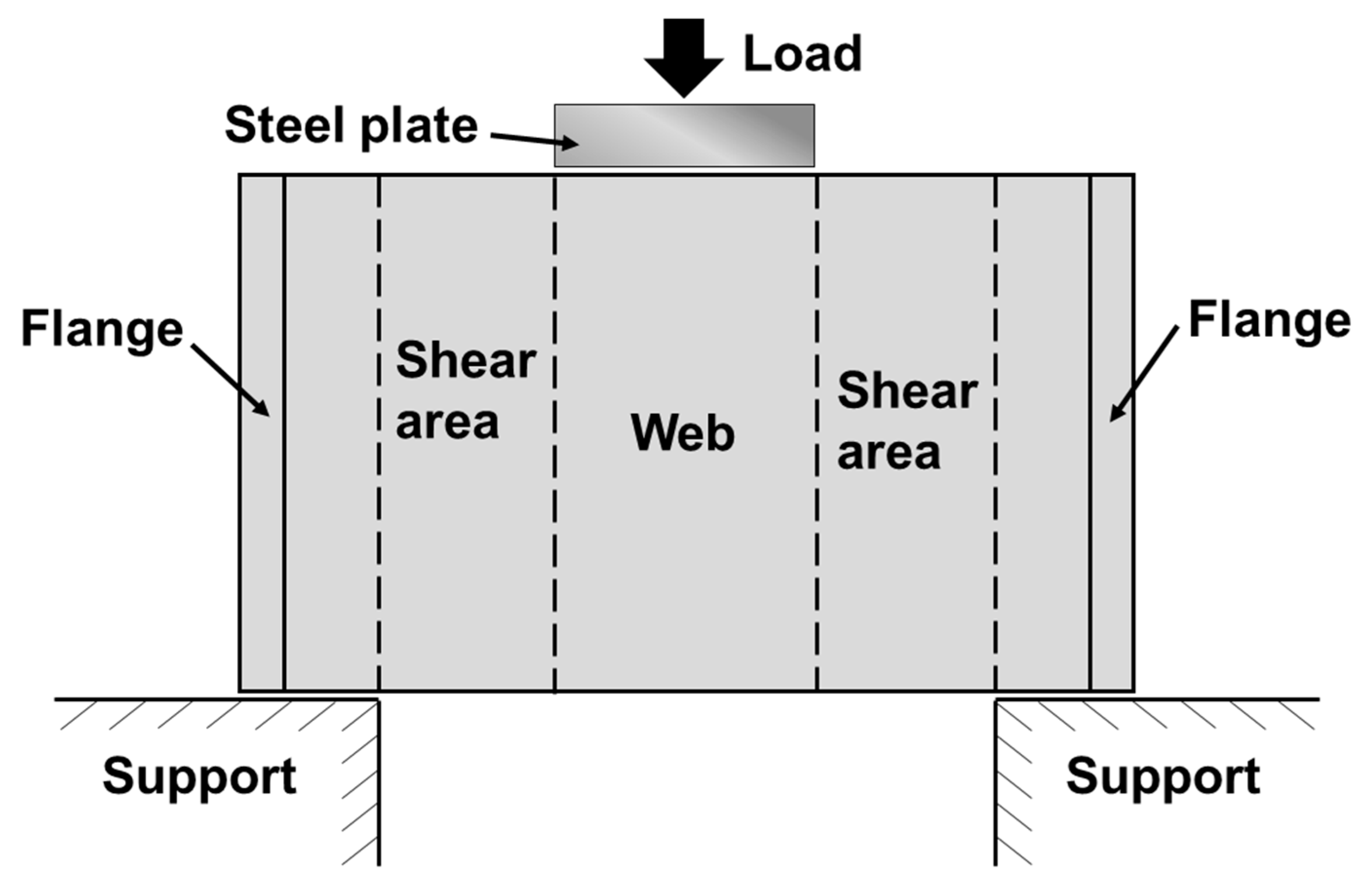
4. Determining the Shear Behavior of the Built-Up FRPs Using Direct Shear Test
- (i)
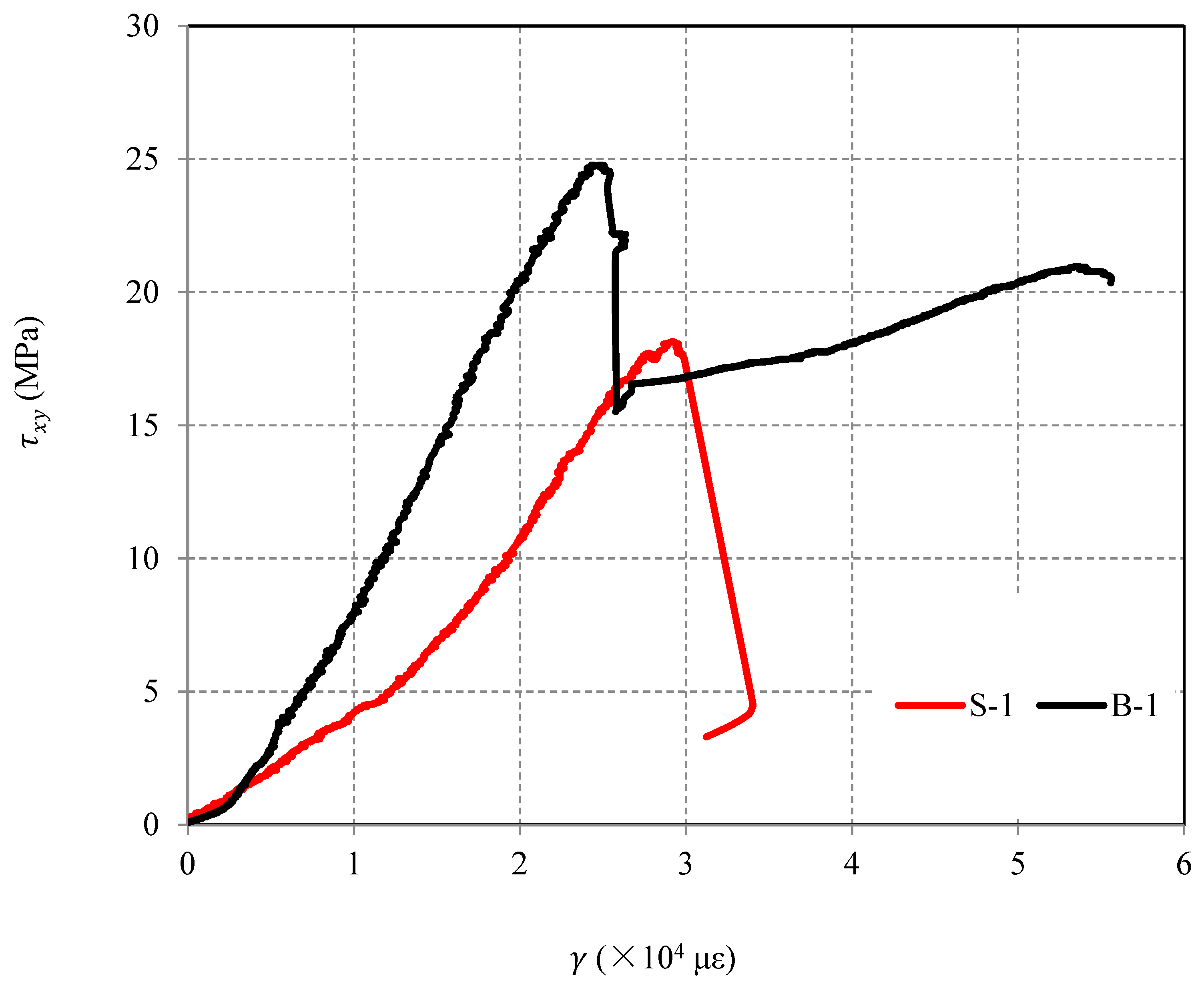
- Elastic stage: The three parts of the web work together to resist the load, causing the shear stress to increase linearly until the load peak.
- (ii)
- Debonding and crack stage: The shear load/stress slightly decreases at the load peak, after which the hand-up sandwich part holds the main load and contributes most to the constantly increasing deformation until failure. The viscous deformation is a result of the absence of high curing temperatures of the matrix in the hand-up laminated webs, as high temperature and high pressure increase brittleness. The – curves demonstrate pseudo-ductility in this stage.
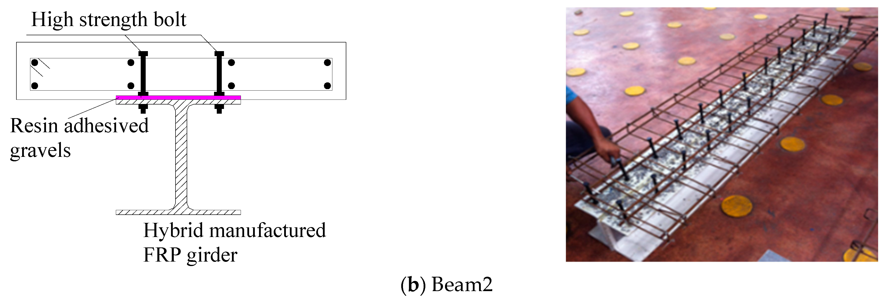
5. Experimental Validation Using FRP–Concrete Composite Beams
5.1. Method
5.2. Test Observations and Load Responses
- (i)
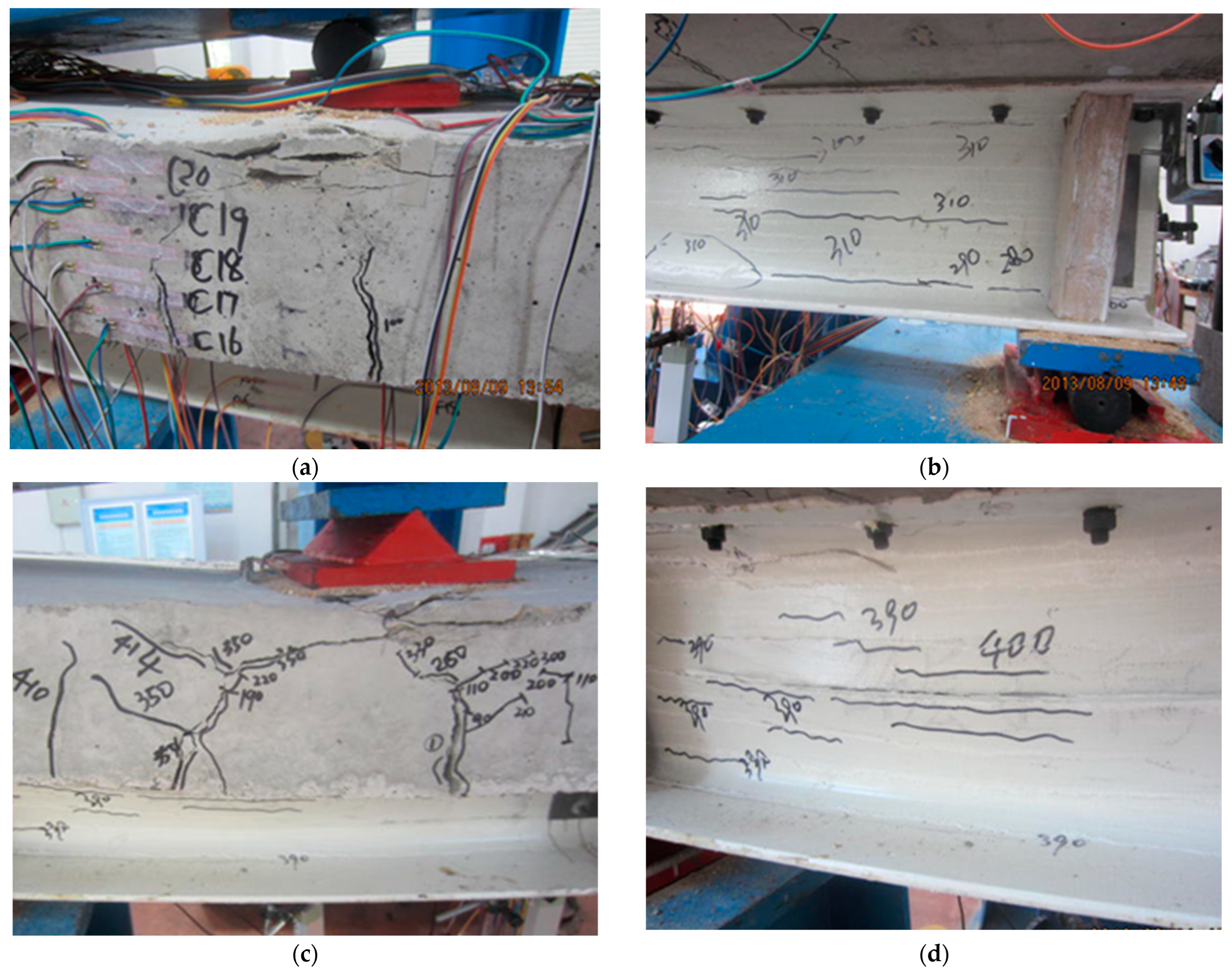
- The elastic stage (0–0.2 ): the concrete slab cracked at about 0.15 , albeit without really affecting the overall flexural stiffness, see Figure 11. The cracks formed at the mid-span of the beam at the bottom of RC slab, and then propagated to the upper vertical direction), see Figure 12 and Figure 13. Interestingly, Beam_2 had a higher rigidity, which was attributed to the improved shear connection compared with Beam_1.
- (ii)
- The local failure stage (0.2–0.5 Pu): new concrete cracks continuously sprung out within the pure bending section of the concrete slab, and the cracks became wider and longer. Interface debonding between the sandwiched layer and the pultruded layers could be observed, see Figure 12 and Figure 13, and acoustic activities were then heard in the built-up FRP webs.
- (iii)
- The highly damaged stage (0.5–0.8 Pu): the natural bonding force along FRP and concrete interface was destroyed, see Figure 13, as proven by the acoustic activities released; consequently, the bolt stress soared dramatically, and the flexural stiffness of the beam decreased instantly. A neutral axis appeared in concrete and FRP, and the shear span webs cracked horizontally.
- (iv)
- The destruction stage (0.8 ): the FRP webs failed in shear span, while the concrete diagonal cracks of concrete extended to the top and finally led to concrete failure when coupled with compressive stress (Figure 13).
6. Calculation of the Shear Capacity of FRP Webs in the Composite Beams
7. Conclusions
- (i)
- To address the low shear capacity of unidirectional fiber-reinforced polymer (PFRP) materials, a built-up technology based on the pultrusion process was proposed, which involved adding a layer of hand-up fiber sheet between the two pultruded webs, allowing the overall capacity and safety of all-FRP structures and FRP–concrete hybrid structures to be improved.
- (ii)
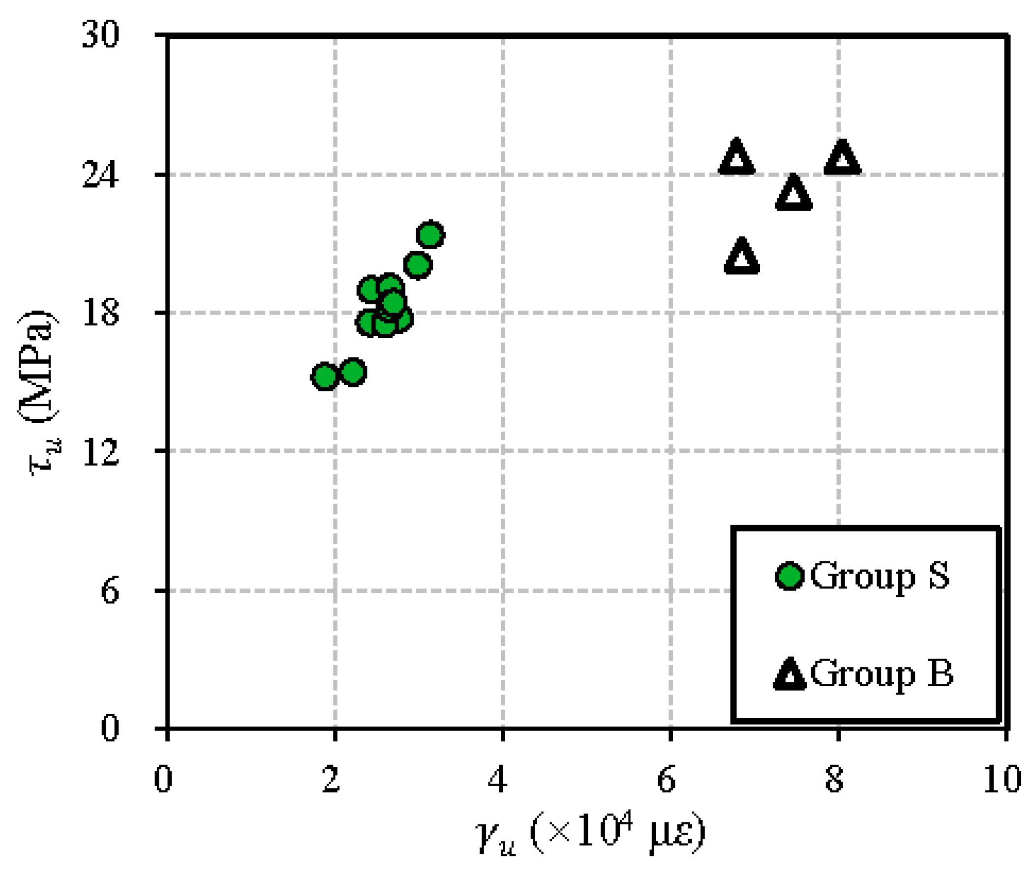
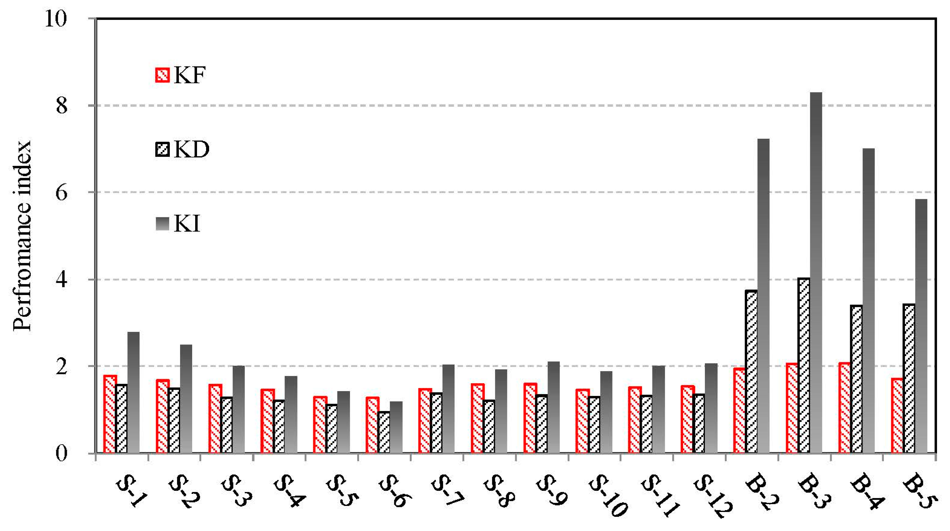
- The results of direct shear tests of 12 PFRP and 4 built-up FRP profiles showed that the PFRP profiles failed in a brittle manner at an average shear strength of 18.2 MPa, whereas the built-up FRP specimens exhibited relatively higher shear strength (23.3 MPa) and near-triple shear deformation capacity.
- (iii)
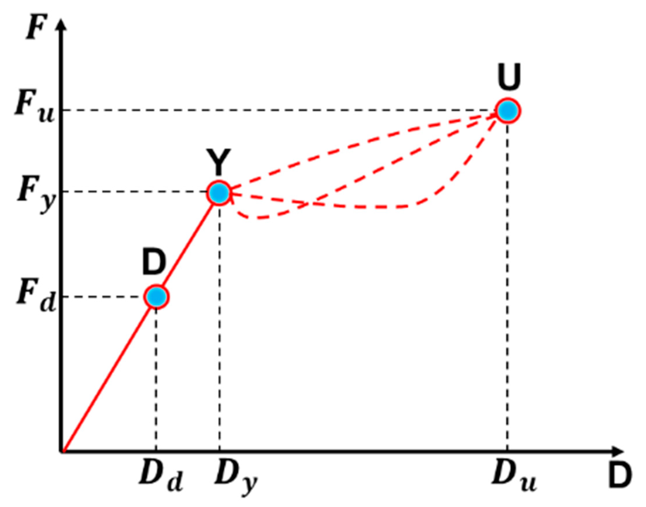
- This study also proposed a safety redundancy index for FRP shear failure to quantify the pseudo-ductility of built-up FRP. The results showed that built-up FRP had 1.5 times the capacity and 2.8 times the ultimate redundancy compared to pultruded FRP.
Author Contributions
Funding
Data Availability Statement
Acknowledgments
Conflicts of Interest
Nomenclature and Abbreviations
| cross-sectional area of stirrups | |
| section area of FRP webs | |
| width of concrete slab | |
| CFRP | carbon fiber-reinforced polymers |
| ultimate deformation | |
| EB | externally bonded |
| tensile strength of concrete | |
| FRP | fiber-reinforced polymers |
| strength of stirrups | |
| height of concrete slab | |
| effective height of concrete slab | |
| deformation redundancy index | |
| capacity redundancy index | |
| general index | |
| ultimate bearing capacity | |
| PFRP | pultruded fiber reinforced polymers |
| space of stirrups | |
| UHPC | ultra-high-performance concrete |
| shear capacity carried by concrete the reinforced bars | |
| shear capacity carried by FRP webs | |
| total shear capacity of the section | |
| shear span ratio of concrete slab | |
| shear strength of FRP webs |
References
- Hollaway, L.C. A review of the present and future utilisation of FRP composites in the civil infrastructure with reference to their important in-service properties. Constr. Build. Mater. 2010, 24, 2419–2445. [Google Scholar] [CrossRef]
- Liu, T.; Liu, X.; Feng, P. A comprehensive review on mechanical properties of pultruded FRP composites subjected to long-term environmental effects. Compos. Part B Eng. 2020, 191, 107958. [Google Scholar] [CrossRef]
- Syamsir, A.; Ean, L.W.; Asyraf, M.R.M.; Supian, A.B.M.; Madenci, E.; Özkılıç, Y.O.; Aksoylu, C. Recent Advances of GFRP Composite Cross Arms in Energy Transmission Tower: A Short Review on Design Improvements and Mechanical Properties. Materials 2023, 16, 2778. [Google Scholar] [CrossRef] [PubMed]
- Aksoylu, C.; Özkılıç, Y.O.; Madenci, E.; Safonov, A. Compressive behavior of pultruded GFRP boxes with concentric openings strengthened by different composite wrappings. Polymers 2022, 14, 4095. [Google Scholar] [CrossRef]
- Habibi, T.; Rhode-Barbarigos, L.; Keller, T. Fiber-polymer composites for permanent large-scale bending-active elastica beams. Compos. Struct. 2022, 294, 115809. [Google Scholar] [CrossRef]
- Chen, Y.; Duan, M.; Zou, X.; Feng, Y.; Li, G. Experimental and Numerical Investigation of Joints for a Pultruded Fiber-Reinforced Polymer Truss. Polymers 2022, 14, 4810. [Google Scholar] [CrossRef]
- Zou, X.; Lin, H.; Feng, P.; Bao, Y.; Wang, J. A review on FRP-concrete hybrid sections for bridge applications. Compos. Struct. 2021, 262, 113336. [Google Scholar] [CrossRef]
- Yang, X.; Bai, Y.; Ding, F. Structural performance of a large-scale space frame assembled using pultruded GFRP composites. Compos. Struct. 2015, 133, 986–996. [Google Scholar] [CrossRef]
- Keller, T.; Bai, Y.; Vallée, T. Long-term performance of a glass fiber-reinforced polymer truss bridge. J. Compos. Constr. 2007, 11, 99–108. [Google Scholar] [CrossRef]
- Zou, X.; Feng, Y.; Zhong, R.; Fang, T.; Wang, J. An experimental study of FRP truss side plate joint. Constr. Build. Mater. 2023, 365, 130012. [Google Scholar] [CrossRef]
- Zou, X.; Wang, J. Experimental study on joints and flexural behavior of FRP truss-UHPC hybrid bridge. Compos. Struct. 2018, 203, 414–424. [Google Scholar] [CrossRef]
- El-Hacha, R.; Chen, D. Behaviour of hybrid FRP–UHPC beams subjected to static flexural loading. Compos. Part B Eng. 2012, 43, 582–593. [Google Scholar] [CrossRef]
- Correia, J.R.; Branco, F.A.; Ferreira, J.G. Flexural behaviour of GFRP–concrete hybrid beams with interconnection slip. Compos. Struct. 2007, 77, 66–78. [Google Scholar] [CrossRef]
- Siwowski, T.; Rajchel, M.; Kaleta, D.; Własak, L. The first Polish road bridge made of FRP composites. Struct. Eng. Int. 2017, 27, 308–314. [Google Scholar] [CrossRef]
- Zhang, P.; Hu, R.; Zou, X.; Liu, Y.; Li, Q.; Wu, G.; Sheikh, S.A. Experimental study of a novel continuous FRP-UHPC hybrid beam. Compos. Struct. 2021, 261, 113329. [Google Scholar] [CrossRef]
- Keller, T. Recent all-composite and hybrid fibre-reinforced polymer bridges and buildings. Prog. Struct. Eng. Mater. 2001, 3, 132–140. [Google Scholar] [CrossRef]
- Zou, X.; Feng, P.; Bao, Y.; Wang, J.; Xin, H. Experimental and analytical studies on shear behaviors of FRP-concrete composite sections. Eng. Struct. 2020, 215, 110649. [Google Scholar] [CrossRef]
- Zhang, P.; Lv, X.; Liu, Y.; Zou, X.; Li, Y.; Wang, J.; Sheikh, S.A. Novel fiber reinforced polymers (FRP)-ultrahigh performance concrete (UHPC) hybrid beams with improved shear performance. Constr. Build. Mater. 2021, 286, 122720. [Google Scholar] [CrossRef]
- He, J.; Xian, G. Debonding of CFRP-to-steel joints with CFRP delamination. Compos. Struct. 2016, 153, 12–20. [Google Scholar] [CrossRef]
- Biscaia, H.C.; Cruz, D.; Chastre, C. Analysis of the debonding process of CFRP-to-timber interfaces. Constr. Build. Mater. 2016, 113, 96–112. [Google Scholar] [CrossRef]
- Zou, X.; Mirala, A.; Sneed, L.H.; Al Qaseer, M.T.; Donnell, K. Detection of CFRP-concrete interfacial debonding using active microwave thermography. Compos. Struct. 2021, 260, 113261. [Google Scholar] [CrossRef]
- Zhou, X.Y.; Qian, S.Y.; Wang, N.W.; Xiong, W.; Wu, W.Q. A review on stochastic multiscale analysis for FRP composite structures. Compos. Struct. 2022, 284, 115132. [Google Scholar] [CrossRef]
- Bank, L.C. Shear properties of pultruded glass FRP materials. J. Mater. Civ. Eng. 1990, 2, 118–122. [Google Scholar] [CrossRef]
- Bai, Y.; Keller, T. Shear failure of pultruded fiber-reinforced polymer composites under axial compression. J. Compos. Constr. 2009, 13, 234–242. [Google Scholar] [CrossRef]
- Gui, L.L.; Zhou, H.W.; Wang, H.W. Theoretical analysis of young’s modulus for unidirectional fiber reinforced composites with different fiber orientations. In Advanced Materials Research; Trans Tech Publications Ltd.: Chongqing, China, 2011; Volume 216, pp. 773–776. [Google Scholar]
- Guo, L.; Dong, G. Ways to elevate the transverse strength of pultrusion composites. Fiber Reinf. Plast. Compos. 1998, 1, 17–19. (In Chinese) [Google Scholar]
- Hu, X.; Ma, Y. Strength analysis of RTM continuous GF reinforced composites. Fiber Reinf. Plast. Compos. 1997, 2, 3–4. (In Chinese) [Google Scholar]
- Jiang, K.; Chen, L.; Zhao, Q. Study on the moulding process and bending properties of multi-directional laminated pultruded thin-walled FRP beam. Eng. Plast. Appl. 2011, 39, 42–46. [Google Scholar]
- Liu, T.; Feng, P.; Tang, J.; Liu, X. Pullwinding technique for realizing hybrid roving architecture in pultruded GFRP composites. Compos. Struct. 2023, 305, 116483. [Google Scholar] [CrossRef]
- Alajarmeh, O.; Alhawamdeh, M.; Shelley, T.; Mohammed, A.; Nicol, L.; Schubel, P.; Zeng, X. Influence of post-processing on the compressive behaviour of full-scale pultruded FRP columns: Holes and inserts. Eng. Struct. 2022, 266, 114547. [Google Scholar] [CrossRef]
- Liu, Y.; Zhang, H.T.; Tafsirojjaman, T.; Dogar, A.U.R.; AlAjarmeh, O.; Yue, Q.R.; Manalo, A. A novel technique to improve the compressive strength and ductility of glass fiber reinforced polymer (GFRP) composite bars. Constr. Build. Mater. 2022, 326, 126782. [Google Scholar] [CrossRef]
- Ye, L.; Feng, P.; Lin, X. Analysis of safety margin indices for structural members with FRP. China Civ. Eng. J. 2009, 42, 21. (In Chinese) [Google Scholar]
- Vedernikov, A.; Gemi, L.; Madenci, E.; Özkılıç, Y.O.; Yazman, Ş.; Gusev, S.; Safonov, A. Effects of high pulling speeds on mechanical properties and morphology of pultruded GFRP composite flat laminates. Compos. Struct. 2022, 301, 116216. [Google Scholar] [CrossRef]
- Madenci, E.; Özkılıç, Y.O.; Aksoylu, C.; Safonov, A. The effects of eccentric web openings on the compressive performance of pultruded GFRP boxes wrapped with GFRP and CFRP sheets. Polymers 2022, 14, 4567. [Google Scholar] [CrossRef] [PubMed]
- Özkılıç, Y.O.; Gemi, L.; Madenci, E.; Aksoylu, C. Effects of stirrup spacing on shear performance of hybrid composite beams produced by pultruded GFRP profile infilled with reinforced concrete. Arch. Civ. Mech. Eng. 2022, 23, 36. [Google Scholar] [CrossRef]
- Gemi, L.; Madenci, E.; Özkılıç, Y.O. Experimental, analytical and numerical investigation of pultruded GFRP composite beams infilled with hybrid FRP reinforced concrete. Eng. Struct. 2021, 244, 112790. [Google Scholar] [CrossRef]
- Gemi, L.; Madenci, E.; Özkılıç, Y.O.; Yazman, Ş.; Safonov, A. Effect of fiber wrapping on bending behavior of reinforced concrete filled pultruded GFRP composite hybrid beams. Polymers 2022, 14, 3740. [Google Scholar] [CrossRef]
- Kitane, Y.; Aref, A.J.; Lee, G.C. Static and fatigue testing of hybrid fiber-reinforced polymer-concrete bridge superstructure. J. Compos. Constr. 2004, 8, 182–190. [Google Scholar] [CrossRef]
- Aref, A.J.; Kitane, Y.; Lee, G.C. Analysis of hybrid FRP-concrete multi-cell bridge superstructure. Compos. Struct. 2005, 69, 346–359. [Google Scholar] [CrossRef]
- Mufti, A.A.; Labossière, P.; Neale, K.W. Recent bridge applications of FRPs in Canada. Struct. Eng. Int. 2002, 12, 96–98. [Google Scholar] [CrossRef]
- Deskovic, N.; Triantafillou, T.C.; Meier, U. Innovative design of FRP combined with concrete: Short-term behavior. J. Struct. Eng. 1995, 121, 1069–1078. [Google Scholar] [CrossRef]
- Zou, Y.; Wu, C.; Zhang, Z.; Jiang, J.; Yu, K.; Wang, X. Investigation on flexural behavior of novel GFRP grid web-concrete hybrid beam. Eng. Struct. 2023, 278, 115489. [Google Scholar] [CrossRef]
- Feng, P.; Qiang, H.; Ye, L. Discussion and definition on yield points of materials, members and structures. Eng. Mech. 2017, 34, 36–46. (In Chinese) [Google Scholar]
- GB 50010-2010; Code for Design of Concrete Structures. China Building Industry Press: Beijing, China, 2011. (In Chinese)
- Nie, J.; Cai, C.S. Steel–concrete composite beams considering shear slip effects. J. Struct. Eng. 2003, 129, 495–506. [Google Scholar] [CrossRef]
- Nie, J.; Xiao, Y.; Chen, L. Experimental studies on shear strength of steel–concrete composite beams. J. Struct. Eng. 2004, 130, 1206–1213. [Google Scholar] [CrossRef]


| Specimen ID | Layout of Web Core | Pu (kN) | Du (mm) | τu (MPa) | γu (×104 με) | KF | KD | KI |
|---|---|---|---|---|---|---|---|---|
| S-1 | - | 85.4 | 3.13 | 21.35 | 3.13 | 1.78 | 1.57 | 2.78 |
| S-2 | - | 80.25 | 2.98 | 20.06 | 2.98 | 1.67 | 1.49 | 2.49 |
| S-3 | - | 75.6 | 2.55 | 18.90 | 2.55 | 1.58 | 1.28 | 2.01 |
| S-4 | - | 70.3 | 2.41 | 17.58 | 2.41 | 1.47 | 1.21 | 1.77 |
| S-5 | - | 61.73 | 2.21 | 15.43 | 2.21 | 1.29 | 1.11 | 1.42 |
| S-6 | - | 60.9 | 1.88 | 15.23 | 1.88 | 1.27 | 0.94 | 1.19 |
| S-7 | - | 70.98 | 2.76 | 17.75 | 2.76 | 1.48 | 1.38 | 2.04 |
| S-8 | - | 75.93 | 2.43 | 18.98 | 2.43 | 1.58 | 1.22 | 1.92 |
| S-9 | - | 76.35 | 2.65 | 19.09 | 2.65 | 1.59 | 1.33 | 2.11 |
| S-10 | - | 70.03 | 2.59 | 17.51 | 2.59 | 1.46 | 1.30 | 1.89 |
| S-11 | - | 72.85 | 2.64 | 18.21 | 2.64 | 1.52 | 1.32 | 2.00 |
| S-12 | - | 77.01 | 2.69 | 18.43 | 2.69 | 1.54 | 1.35 | 2.07 |
| B-1 | (0°/90°)6 | 204.65 | 7.46 | 22.6 | 7.46 | 1.94 | 3.73 | 7.23 |
| B-2 | (0°/90°)12 | 237.65 | 8.04 | 24.76 | 8.04 | 2.06 | 4.02 | 8.29 |
| B-3 | (±45°)24 | 267.58 | 6.78 | 24.78 | 6.78 | 2.07 | 3.39 | 7.00 |
| B-4 | (0°/90°)24 | 221.55 | 6.84 | 20.51 | 6.84 | 1.71 | 3.42 | 5.85 |
| Beam ID | Pcr (kN) | Pslip,i (kN) | Pslip,u (kN) | Pweb,sh (kN) | Pweb,u (kN) | Pu (kN) |
|---|---|---|---|---|---|---|
| Beam_1 | 100 | 100 | 310 | 310 | - | 414 |
| Beam_2 | 80 | 100 | 225 | 280 | 410 | 410 |
| Beams | τFRP (MPa) | VFRP (kN) | fcu (MPa) | Vcs (kN) | Vtotal (kN) | Vtest (kN) | ||
|---|---|---|---|---|---|---|---|---|
| Beam_1 | 27.02 | 161.58 | 33.40 | 69.18 | 230.76 | 207.00 | 1.11 | 0.30 |
| Beam_2 | 27.02 | 161.58 | 32.80 | 68.42 | 230.00 | 205.00 | 1.12 | 0.30 |
Disclaimer/Publisher’s Note: The statements, opinions and data contained in all publications are solely those of the individual author(s) and contributor(s) and not of MDPI and/or the editor(s). MDPI and/or the editor(s) disclaim responsibility for any injury to people or property resulting from any ideas, methods, instructions or products referred to in the content. |
© 2023 by the authors. Licensee MDPI, Basel, Switzerland. This article is an open access article distributed under the terms and conditions of the Creative Commons Attribution (CC BY) license (https://creativecommons.org/licenses/by/4.0/).
Share and Cite
Zhang, Q.; Xu, Z.; Hu, Y. Built-Up Fiber-Reinforced Polymers (FRP) Profiles with Improved Shear Performance for FRP–Concrete Hybrid Section. Buildings 2023, 13, 2298. https://doi.org/10.3390/buildings13092298
Zhang Q, Xu Z, Hu Y. Built-Up Fiber-Reinforced Polymers (FRP) Profiles with Improved Shear Performance for FRP–Concrete Hybrid Section. Buildings. 2023; 13(9):2298. https://doi.org/10.3390/buildings13092298
Chicago/Turabian StyleZhang, Qifeng, Zuohong Xu, and Yuqing Hu. 2023. "Built-Up Fiber-Reinforced Polymers (FRP) Profiles with Improved Shear Performance for FRP–Concrete Hybrid Section" Buildings 13, no. 9: 2298. https://doi.org/10.3390/buildings13092298