Article

Constitutive Model of FRP Tube-Confined Alkali-Activated Slag Lightweight Aggregate Concrete Columns under Axial Compression

1
Zhong Jiao Jian Ji Jiao Highway Investment Development Co., Ltd., Shijiazhuang 050043, China
2
Key Lab of Structures Dynamic Behaviour and Control of the Ministry of Education, Harbin Institute of Technology, Harbin 150090, China
3
School of Civil and Transportation Engineering, Hebei University of Technology, Tianjin 300401, China
4
Faculty of Architecture, Civil and Transportation Engineering, Beijing University of Technology, Beijing 100124, China
5
Hebei Shenbao Investment Development Co., Ltd., Baoding 071400, China
*
Author to whom correspondence should be addressed.
Buildings 2023, 13(9), 2284; https://doi.org/10.3390/buildings13092284
Submission received: 7 July 2023 / Revised: 31 August 2023 / Accepted: 6 September 2023 / Published: 8 September 2023
(This article belongs to the Collection Advanced Concrete Structures in Civil Engineering)

Abstract

:
Fiber reinforced polymer (FRP), as a novel type of composite material, has been extensively employed in structural strengthening and composite structures. The FRP tube-confined alkali-activated slag lightweight aggregate concrete column (FRP-AASLAC) can effectively improve the utilization rate of slag, reduce carbon emissions, reduce structural self-weight, and improve structural ductility. Therefore, the axial compressive properties of FRP-AASLAC were studied in this paper. The influences of the type of FRP, FRP thickness and the content of lightweight aggregate on the failure modes, bearing capacities, deformation properties and constitutive relationships of FRP-AASLAC were revealed. The results indicate that the constitutive relationships of FRP-AASLAC show double broken line patterns without obvious softening sections. The restraining effect of FRP on lightweight aggregate concrete is higher than that on ordinary concrete as lightweight aggregate concrete has lower strength and more easily undergoes lateral expansion under external loads. Models for compressive strength, peak compressive strain and constitutive relationship for FRP-AASLAC are proposed.

1. Introduction

Cement production requires energy and releases a lot of carbon dioxide [1,2,3,4]. According to statistics, total cement production in China in 2020 reached 2.38 billion tons, accounting for 55% of the world’s total cement production. It produces carbon emissions of up to 1.47 billion tons, accounting for 84.3% of the total carbon emissions of the building material industry, causing serious pollution of the environment [5]. As an industrial waste product, the annual output of granulated blast furnace slag in China alone reached as high as 102 million tons, but only 20–30% is utilized as a resource, and the remaining 70–80% is idle and cannot be used effectively [6,7]. Alkali-activated slag cementitious material is prepared by granulated blast furnace slag instead of cement and excited by an alkali activator, which can reduce cement consumption and carbon emission, and improve the utilization rate of granulated blast furnace slag. It is a kind of green and environmentally-friendly building material [8,9].
Compared with natural aggregate, lightweight aggregate has the advantages of light weight and high strength, heat preservation and heat insulation, anti-freezing, and alkali resistance [10,11,12,13,14]. In addition, it comes from a wide range of sources and varieties. It can be prepared directly from porous rock or synthesized artificially from industrial waste such as fly ash, sludge and tailings, and has been widely studied and applied in building materials [15,16,17,18,19]. Alkali-activated slag lightweight aggregate concrete (AASLAC) uses alkali-activated slag as a cementitious material and lightweight aggregate as a coarse aggregate, which not only has the green and environmental protection characteristics of alkali-activated slag cementitious materials but also has the characteristics of light weight, high strength, heat preservation and heat insulation of lightweight aggregate concrete, so it has prospects for broad application in architectural engineering [20].
Alkali-activated slag cementitious material has the disadvantages of fast reaction speed, large shrinkage deformation and poor material toughness [21]. In addition, lightweight aggregate has a suction cup water effect, which can absorb water in the early stage of the alkali-activation reaction, accelerate the reaction speed and further reduce the toughness of alkali-activated slag lightweight aggregate concrete [22]. One of the main ways to improve the toughness of materials is to transform the unitary concrete structure into a dual or even multiple confined composite structure [23,24,25]. At present, the most common composite structures are steel restrained systems and FRP restrained systems. Compared with the steel restrained system, the FRP restrained system can improve the bearing capacity and ductility of the structure and solve the corrosion problem of the steel restrained system. When alkali-activated slag lightweight aggregate concrete is placed in the FRP tube, the FRP tube can be used as the formwork for concrete pouring, and the problem of the poor ductility of alkali-activated slag lightweight aggregate concrete can be solved. At the same time, the bearing capacity can be improved, the effective section size can be reduced, and the structural durability can be improved. It is suitable for marine engineering, bridges and underground structural systems under high temperatures, high salt and high humidity [26,27].
Currently, research on the confinement mechanism of FRP-confined concrete columns concentrates on FRP-confined ordinary concrete columns, FRP-confined high-strength concrete columns, and FRP-confined ultra-high-strength concrete columns. For instance, Zohrevand and Mirmiran [28] suggested that the confinement mechanism of FRP-confined ultra-high-strength concrete columns is similar to that of ordinary concrete, and the destructive modes all exhibit as compressive expansions of the core concrete and circumferential tearing of the FRP tube, resulting in the failures of the specimens. However, FRP-confined ordinary concrete columns exhibit better ductility, while FRP-confined high-strength concrete columns show significant brittleness. This result is attributed to the superior expansive ability of ultra-high-strength concrete compared to high-strength concrete [29]. Alkali-activated slag cementitious material and lightweight aggregate have distinct material characteristics. Therefore, compared to high-strength concrete and ultra-high-strength concrete, AASLAC exhibits different axial mechanical behaviours. As a result, there is an urgent need to study the confinement mechanism of FRP-AASLAC under various confinement levels.
At present, relevant research on FRP-confined concrete mainly focus on the axial compressive behaviour [30,31,32,33,34], eccentric compressive behaviour [35], durability behaviour [36], seismic behaviour [37,38] and the finite element analysis method [39,40,41] of FRP-confined concrete columns. Different research results are obtained by controlling different parameters, and the details are shown in Table 1.
The typical axial compressive constitutive curves of FRP-confined concrete columns are shown in Figure 1. The change tendency after the turning point can be divided into two types: the strengthening segment and the softening segment, which are defined as strongly and weakly confined concrete, respectively. The reason can be attributed to the difference in the degrees of lateral restraints. At present, there is much research on the axial compressive constitutive models of weakly confined concrete. Fardis (1982) studied the influence of the type of FRP on the axial compressive behaviour of FRP sheet-confined concrete circular columns. Based on the test results, the first axial compressive constitutive model applicable to GFRP (glass fibre reinforced polymer) sheet-confined concrete columns was proposed [42]. Samaan (1998) studied the influence of FRP thickness on the axial compressive behaviours of GFRP tube-confined concrete circular columns, and an axial compressive constitutive model suitable for GFRP tube-confined concrete circular columns was proposed [43]. Youssef (2007) studied the influences of the type of FRP and section shape on the axial compressive behaviours of FRP-confined concrete columns, and a constitutive model of FRP tube-confined concrete columns with circular and rectangular sections was proposed [44]. Based on the test results, Wu and Wei (2012) proposed the axial compressive constitutive model of FRP sheet-confined concrete columns of either circular or rectangular sections [45]. There is relatively little research on the axial compressive constitutive models of strongly confined concrete. Saadatmanesh (1994) studied the influences of type of FRP, FRP thickness and space on the axial compressive behaviours of FRP-confined concrete columns. Based on the steel-confined concrete model proposed by Mander (1988) [46], an axial compressive constitutive model of CFRP (carbon fibre-reinforced polymer) and GFRP sheet-confined concrete circular columns was proposed [47]. This model was also adopted by the ACI design method [48]. Based on the limited test data, Lam and Teng (2003) proposed a two-stage (parabola and linear) constitutive model for FRP-confined concrete columns with strong restraints [35].
Existing research mainly focuses on alkali-activated slag concrete using natural aggregate [49,50,51] and ordinary concrete using lightweight aggregate [52,53,54]. There is little research on alkali-activated slag lightweight aggregate concrete. Moreover, there are no studies on the axial compressive behaviours of FRP-AASLAC.
Therefore, in this paper, the axial compressive behaviours of FRP-AASLAC are studied, and two structural forms of CFRP- and GFRP-confined concrete are considered. Firstly, the failure modes of AASLAC and FRP-AASLAC are analysed. Secondly, the influences of the type of FRP, the thickness of FRP, and the content of lightweight aggregate on the bearing capacity and deformation properties of FRP-AASLAC are studied. Thirdly, the models of existing FRP-confined concrete columns for compressive strength and peak compressive strain are compared with the test results. Finally, the revised models for compressive strength, peak compressive strain, and constitutive relationships under axial compression of FRP-AASLAC are proposed.

2. Experimental Program

2.1. Material Properties
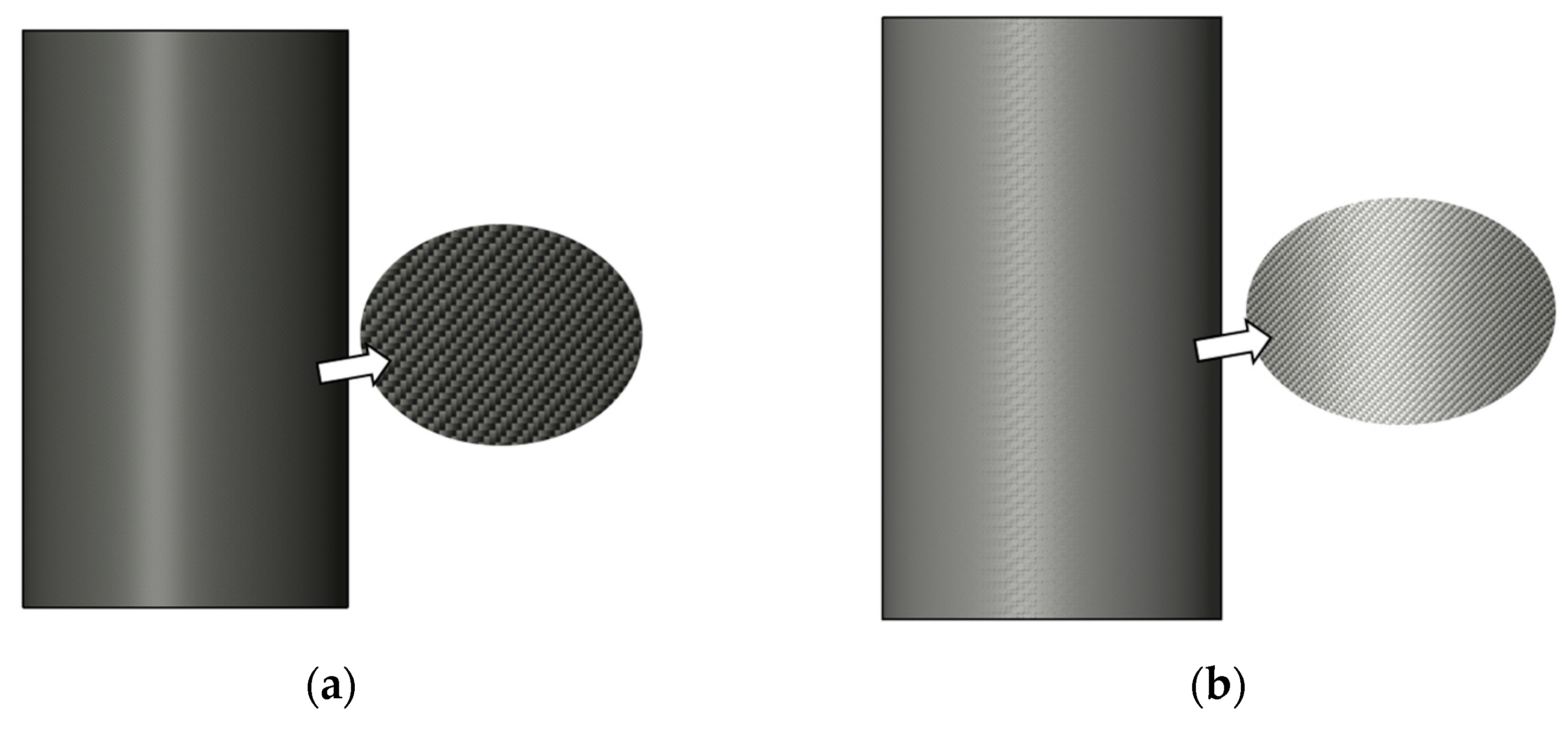
2.1.1. FRP Tubes

As is shown in Figure 2, CFRP and GFRP tubes were used in the test, which were produced standardly by the factory using an autoclave process. The orientation of the fibres is that the hoop fibres are 90 degrees from the longitudinal fibres, and the overlap area of the ends is 100 mm to avoid end debonding failure. The basic properties of the materials are shown in Table 2.

2.1.2. Granulated Blast Furnace Slag

The granulated blast furnace slag is supplied by Polar Bear Building Materials Co., Ltd. in Tangshan, China. The specific gravity of the granulated blast furnace slag used in the test is 2.45, the specific surface area is 440 m2/kg and the average particle size is 2.4 μm. The chemical composition of the granulated blast furnace slag is shown in Table 3.

2.1.3. Fly Ash Aggregate

The fly ash aggregate used in the experiment is supplied by Anhui Kong’s Environmental Technology Co., Ltd., Huainan, China. Due to the higher water absorption rate of fly ash aggregate, to avoid its adverse effects on the working performance and strength of concrete, the fly ash aggregate used in the test is in a saturated surface dry state (Table 4).

2.1.4. Alkali Activator

The alkali activator consists of liquid sodium silicate and solid sodium hydroxide. The liquid sodium silicate was provided by Julide Chemical Co., Ltd. in Yongqing, China, and the solid sodium hydroxide was supplied by Tianjin Dalu Chemical Reagent Factory. The ratio of SiO2 to Na2O in the liquid sodium silicate is 1.7, and the ratio of water is 56%. The purity of the solid sodium hydroxide was 96%. The concentration of the alkali activator was 1495 kg/m3. To prepare the alkali activator, the liquid sodium silicate should be placed into the reaction container first, followed by pouring in water and continuous stirring with a PVC pipe to prevent an incomplete reaction due to residual water at the bottom of the glass. Finally, the solid sodium hydroxide is added to the reaction container and continuously stirred to release heat until no solid particles remain.

2.1.5. Others

River sand was selected as the fine aggregate with a fineness modulus of 2.6 and bulk density of 2480 kg/m3. The natural coarse aggregate was gravel with a particle size range of 5–25 mm and bulk density of 2620 kg/m3. The water used in the test was tap water in Tianjin.

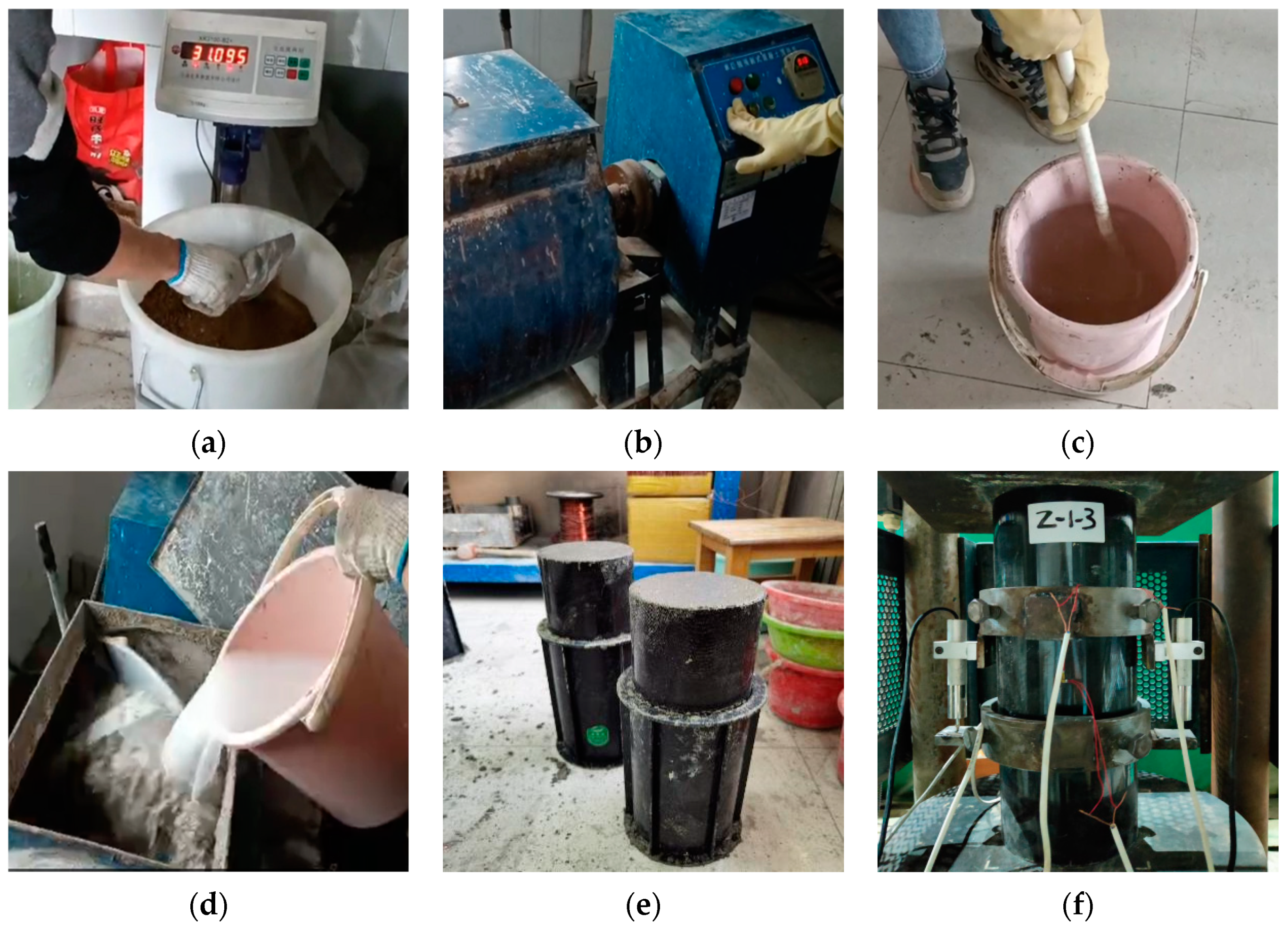
2.2. Preparation of Specimens
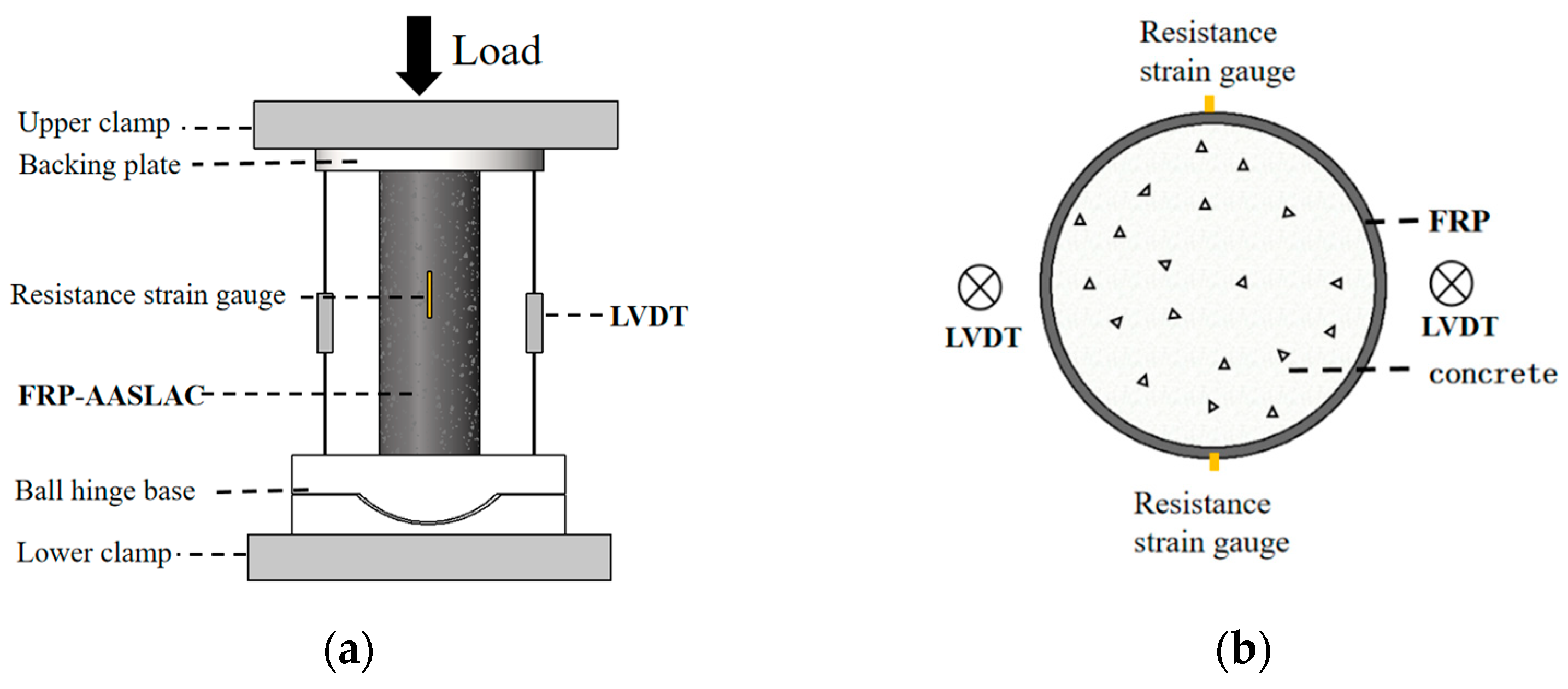
A total of 16 specimens with a diameter of 150 mm and a height of 300 mm, including 12 FRP-AASLAC and 4 reference (i.e., unconfined) cylinders, considered three parameters including the type of FRP (CFRP and GFRP), the number of FRP layers (2, 4 and 6) and the content of lightweight aggregate (natural aggregate, 1/3 replacement rate of natural aggregate, 2/3 replacement rate of natural aggregate and lightweight aggregate). The detailed mix designs of the specimens are shown in Table 5. The specimens are named FRP type—the number of FRP layers—aggregate type—the content of the aggregate. For example, in Table 5, C-2-L-1/3 is the CFRP tube-confined alkali-activated slag lightweight aggregate concrete column. The content of lightweight aggregate is 1/3 and the number of FRP layers is two.
The mix proportions of AASLAC are shown in Table 6. The detailed processes of the preparation of AASLAC and FRP-AASLAC are shown as follows, and the corresponding flow charts are shown in Figure 3: Figure 3a weigh coarse aggregate, slag, river sand, sodium hydroxide, sodium silicate and water, and then place the FRP tube in a cylindrical mould with the release agent applied; Figure 3b prewet the coarse aggregate and stir the prewetted coarse aggregate with slag and river sand evenly; Figure 3c pour the water into the sodium silicate and stir it evenly, and when there is no sediment on the bottom wall of the container, add sodium hydroxide and stir it with a PVC pipe for about 30 s until the sodium hydroxide fully reacts; Figure 3d pour the prepared alkali activator into the concrete mixer and stir it thoroughly; Figure 3e the mixed concrete is poured into the mould according to the layering pouring method, fully vibrated to eliminate air bubbles, and after that, a film is pasted on the upper end of the specimen; Figure 3f transfer the specimen to the normal temperature environment for curing for 28 days. After that, polish both ends flat with an angle grinder for the experiment.
The finished specimen is shown in Figure 4, where σ c is the axial compressive stress on the FRP-AASLAC, σ f   is the lateral constraint stress on the core concrete of the FRP-AASLAC, and σ c f is the reaction force generated by the core concrete under the restraint effect of FRP.

2.3. Test Method

2.3.1. Test Devices

This test adopts the YAW-5000 electrohydraulic servo pressure testing device with a measuring range of 5000 kN. The axial deformation of the specimen was measured by two linear variable differential transformers (LVDTs) placed on the plane of symmetry. LVDTs were fixed at the mid-height level of the specimen through the collar device, and the loading device is shown in Figure 5a. In order to check the accuracy of the measurement of axial deformation, a set of longitudinal strain gauges were symmetrically arranged at the mid-height level of the specimen with a cross-section interval of 180°. The measuring points of the strain gauges are shown in Figure 5b.

2.3.2. Loading System

The test was carried out according to the GB/T 50081-2002 Standard of Test Methods for Mechanical Properties of Ordinary Concrete [55]. The loading process was divided into two stages, and the loading mode was controlled by force-deformation hybrid loading. The loading speed of force control is 0.3 kN/s. When the applied load reaches 60% of the estimated bearing capacity, deformation control is adopted, and the loading rate is maintained at 0.1 mm/min. After the failure of the specimen, the test results are recorded. In order to ensure the uniform force of the specimen, the upper and lower ends of the specimen are smoothed with high-strength cement paste.

3. Test Results and Discussion

3.1. Failure Modes

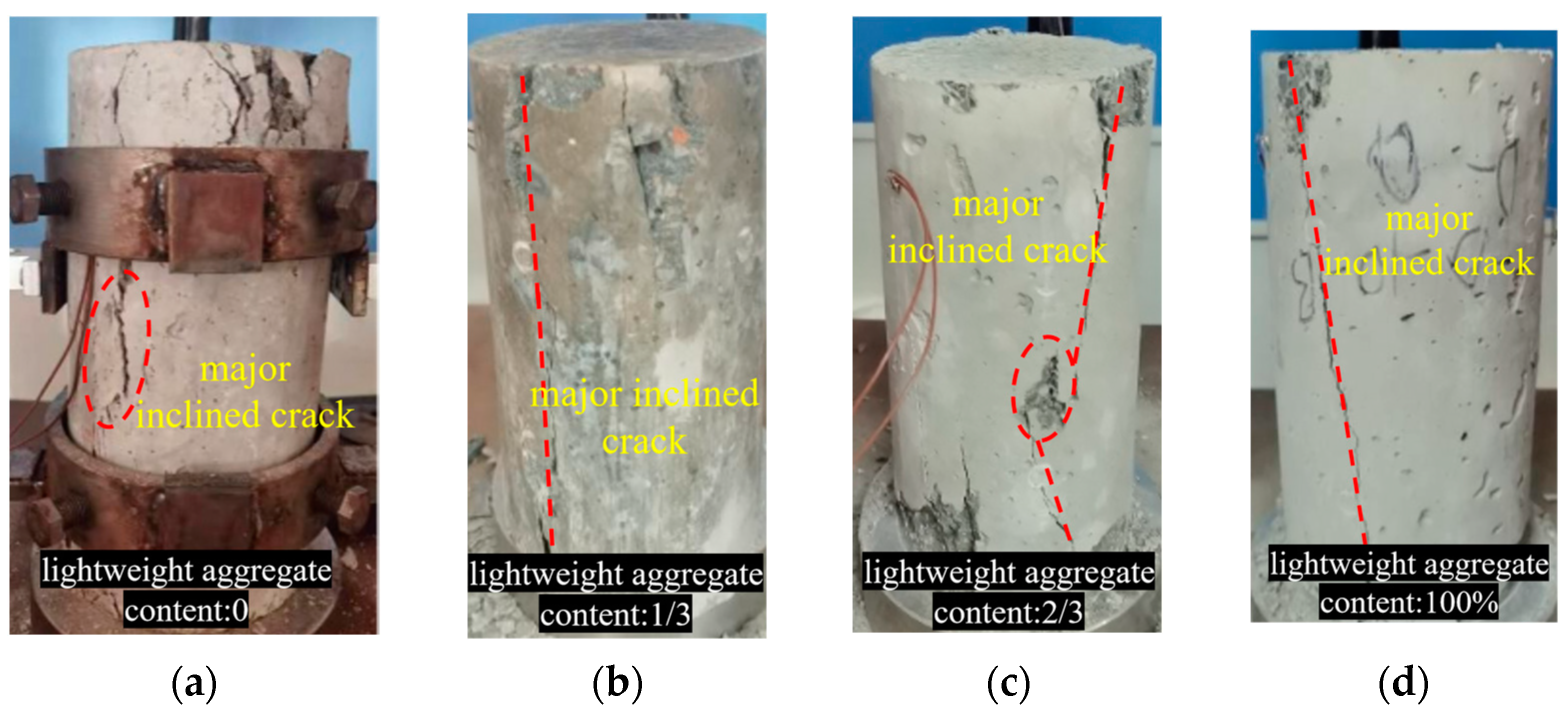
3.1.1. Alkali-Activated Slag Lightweight Aggregate Concrete

The failure modes of AASLAC are shown in Figure 6. AASLAC failed due to concrete crushing. In the early stages of loading, there were no apparent changes in the appearance of the AASLAC specimens. As the applied load approached 60% of the estimated bearing capacity of the AASLAC specimen, cracking sounds could be heard from the interior, and fine cracks appeared on the concrete surface. As the loading continued to reach 80% of the estimated bearing capacity of the AASLAC specimen, the cracking sounds from the interior intensified. When the load reached the bearing capacity of the AASLAC specimen, it failed suddenly along the diagonal direction without any warning signs, accompanied by an explosive sound, exhibiting typical brittle failure characteristics. AASLAC with higher lightweight aggregate content exhibited more pronounced brittleness and more severe failure phenomena.

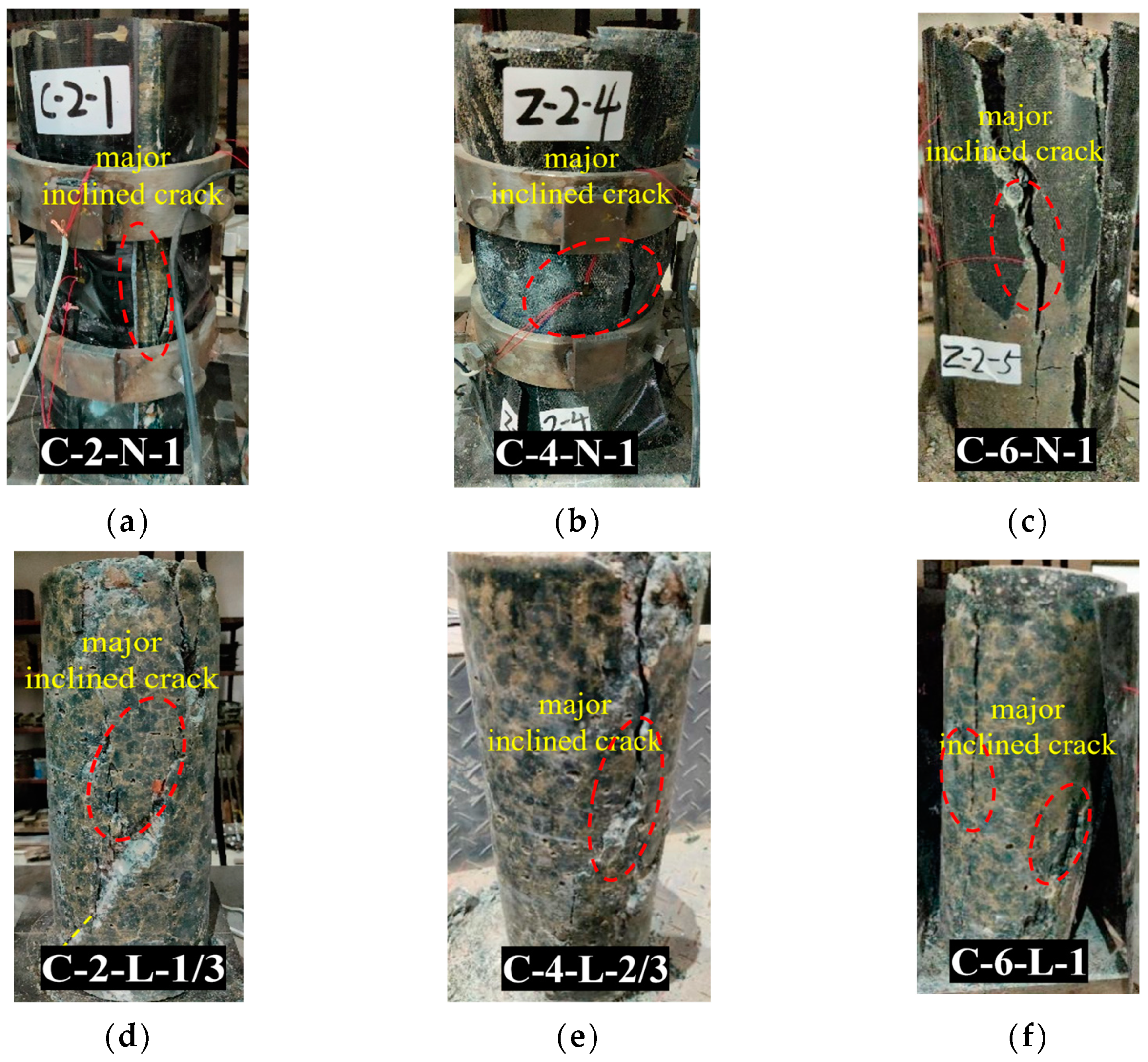
3.1.2. CFRP Tube-Confined Alkali-Activated Slag Lightweight Aggregate Concrete

The failure modes of CFRP-AASLAC are shown in Figure 7. The failure modes of CFRP-AASLAC are characterized by compressive expansion of the core concrete and radial tearing of the FRP tube, resulting in specimen failure. In the initial stages of loading, the constraint effect of the CFRP tube on the core concrete is not significant, and there are no apparent changes in the appearance of the CFRP-AASLAC. As the applied load approached 80% of the axial compressive strength of the core concrete, cracking sounds could be heard from the interior of the CFRP-AASLAC. When the axial compressive strength of the core concrete was reached, the tearing sounds of fibres in the middle portion of the CFRP tube became more intense and denser. When the load increased to the axial compressive strength of the CFRP-AASLAC, the FRP tube burst, resulting in failure of the specimen. As shown in Figure 7, the CFRP-AASLAC fractured diagonally along the diagonal direction, with noticeable fragmentation in the middle of the fracture surface. With an increase in the lightweight aggregate content, the fracture surface of the CFRP-AASLAC became smoother.

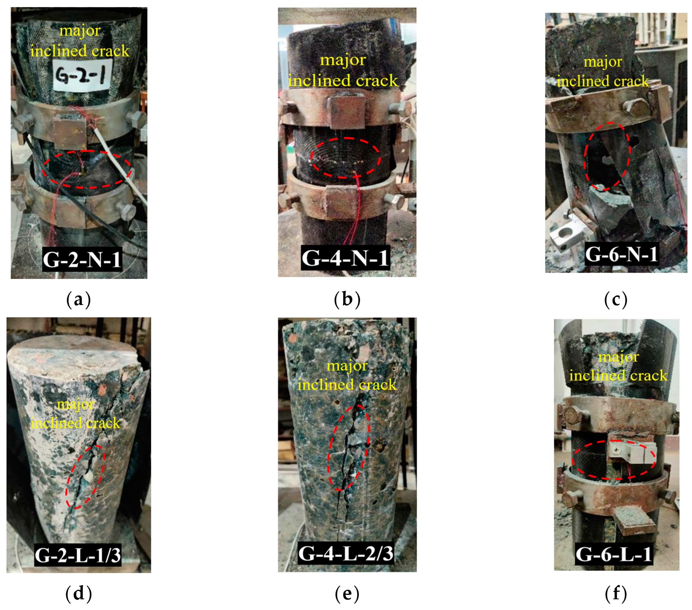
3.1.3. GFRP Tube-Confined Alkali-Activated Slag Lightweight Aggregate Concrete

Failure modes of GFRP-AASLAC are shown in Figure 8. The failure mode of GFRP-AASLAC is characterized by compressive expansion of the core concrete and radial tearing of the FRP tube, resulting in specimen failure. Similar to CFRP-AASLAC, in the initial stages of loading, the external GFRP tube provided limited constraint effect on the core concrete, and there were no apparent changes in the appearance of the GFRP-AASLAC. As the applied load approached 80% of the axial compressive strength of the core concrete, cracking sounds could be heard from the interior of the GFRP-AASLAC. When the axial compressive strength of the core concrete was reached, the tearing sounds of fibres in the middle portion of the GFRP tube became more intense and denser. Upon reaching the axial compressive strength of the GFRP-AASLAC, the specimen experienced longitudinal failure from the middle towards both ends, accompanied by an explosive sound, exhibiting typical brittle failure characteristics. With an increase in the number of layers of the FRP tube, the brittle characteristics of the specimen become more pronounced. Cracks in the GFRP-AASLAC were distributed diagonally, and there was noticeable fragmentation in the middle of the fracture surface.

3.2. Compressive Strength and Peak Compressive Strain

To study the influences for the content of lightweight aggregate, the type of FRP and the thickness of FRP on the compressive strength and peak compressive strain of FRP-AASLAC, the histograms of different specimens are drawn in Figure 9, Figure 10 and Figure 11 according to the requirement of parameter analysis.

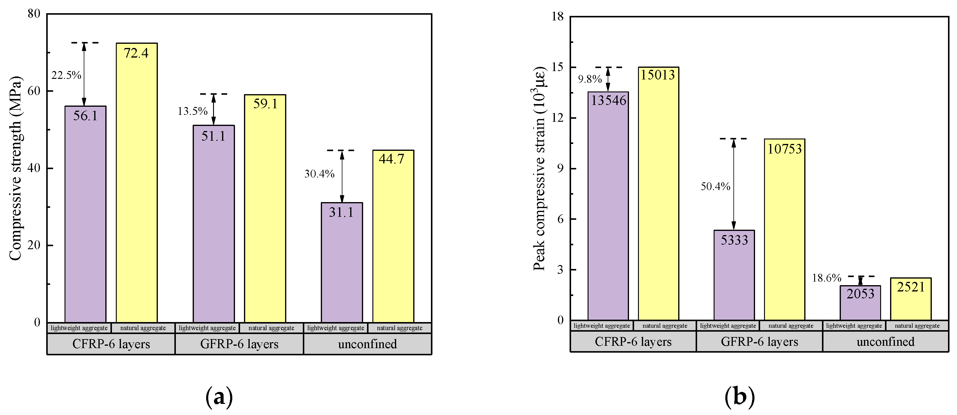
3.2.1. The Content of Lightweight Aggregate

When the type of FRP is controlled as CFRP, and the thickness of CFRP is six layers the influences of the content of lightweight aggregate on the compressive strength and peak compressive strain of FRP-AASLAC are shown in Figure 9, from which the following can be observed.
(1)
The compressive strength of FRP-AASLAC filled with lightweight aggregate is 56.1 MPa, and the peak compressive strain is 13,546 με, while that of FRP-AASLAC filled with natural aggregate is 72.4 MPa, increased by 29.1%. The peak compressive strain is 15,013 με, increased by 10.8%. GFRP-AASLAC showed the same characteristics.
When other parameters are the same, with the increasing content of lightweight aggregate, the elastic modulus of core concrete decreases, the stress required for the deformation of the specimen increases, and the brittleness of FRP-AASLAC is more significant. Therefore, the compressive strength and peak compressive strain of FRP-AASLAC filled with lightweight aggregate decrease [56,57].
(2)
The compressive strength of FRP-AASLAC filled with natural aggregate is approximately 1.6 times that of the core concrete’s compressive strength, and the peak compressive strain is around 5.9 times that of the core concrete’s peak compressive strain. The compressive strength of FRP-AASLAC filled with natural aggregate is roughly 1.8 times that of the core concrete’s compressive strength, and the peak compressive strain is about 6.6 times that of the core concrete’s peak compressive strain. The enhancing effect of FRP on the compressive strength and peak compressive strain of FRP-AASLAC filled with light aggregate is greater than that of FRP-AASLAC filled with natural aggregate.
This is because the restraint effect of FRP is mainly reflected in preventing the radial expansion and cracking of concrete. The AASLAC with a higher content of lightweight aggregate has lower compressive strength and is more likely to undergo lateral expansion under external load. Therefore, the restraint effect of FRP on the AASLAC with higher content of lightweight aggregate is more significant [58].

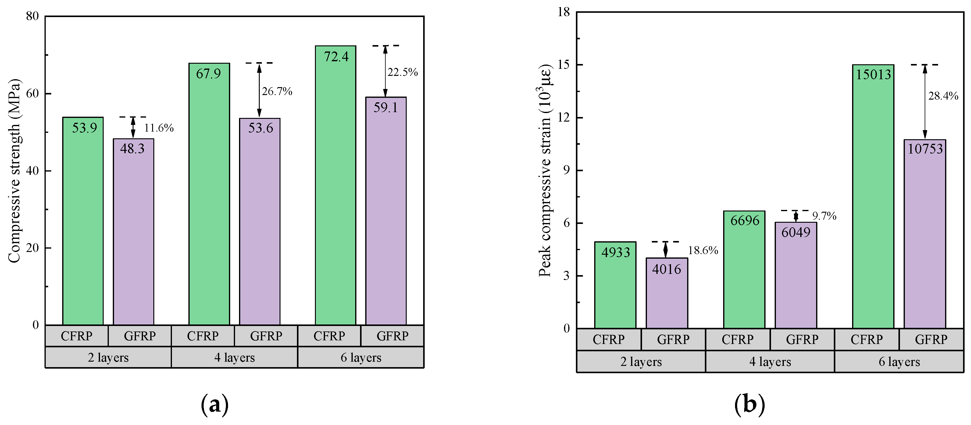
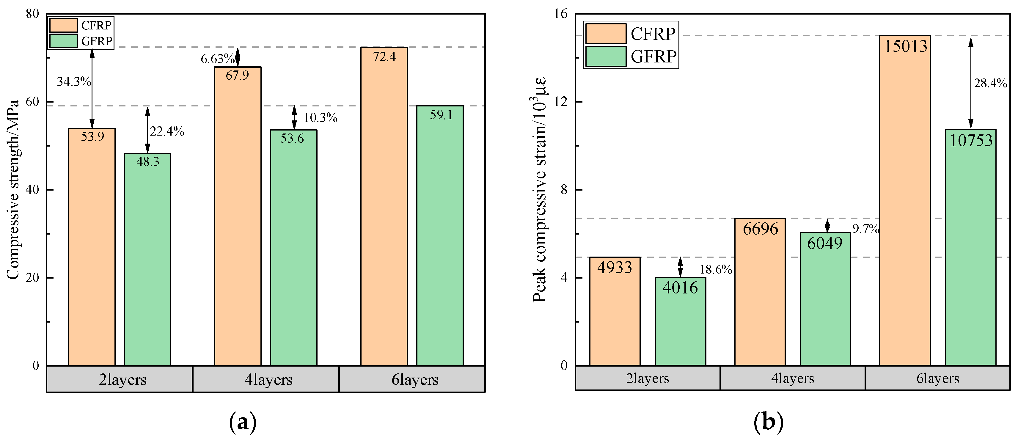
3.2.2. The Type of FRP

When the thickness of the FRP and the content of lightweight aggregates are controlled to be consistent, the influence of the type of FRP on the compressive strength and peak compressive strain of FRP-AASLAC are shown in Figure 10. As can be seen from the figure, the compressive strength and peak compressive strain of the specimens can be significantly improved by the restraint of FRP tubes. When concrete is placed in the FRP tube, it is under three-way confining pressure from the axial load, and its strength and ductility will be effectively improved [30,31,59,60,61,62].
(1)
When the FRP tube has two layers, the compressive strength of GFRP-AASLAC is 89.6% of the compressive strength of CFRP-AASLAC, and the peak compressive strain of GFRP-AASLAC is 81.4% of the peak compressive strain of CFRP-AASLAC.
(2)
When the FRP tubes have 4 and 6 layers, the increased amplitudes of the compressive strength and peak compressive strain of GFRP-AASLAC are lower than those of CFRP-AASLAC.
When the thickness of FRP is the same, CFRP tubes have higher tensile strength and larger elastic modulus, so the restraint effect of CFRP tubes is better than that of GFRP tubes. Under the constraint of CFRP tubes, the specimen has higher bearing capacity and better ductility [63,64,65,66].

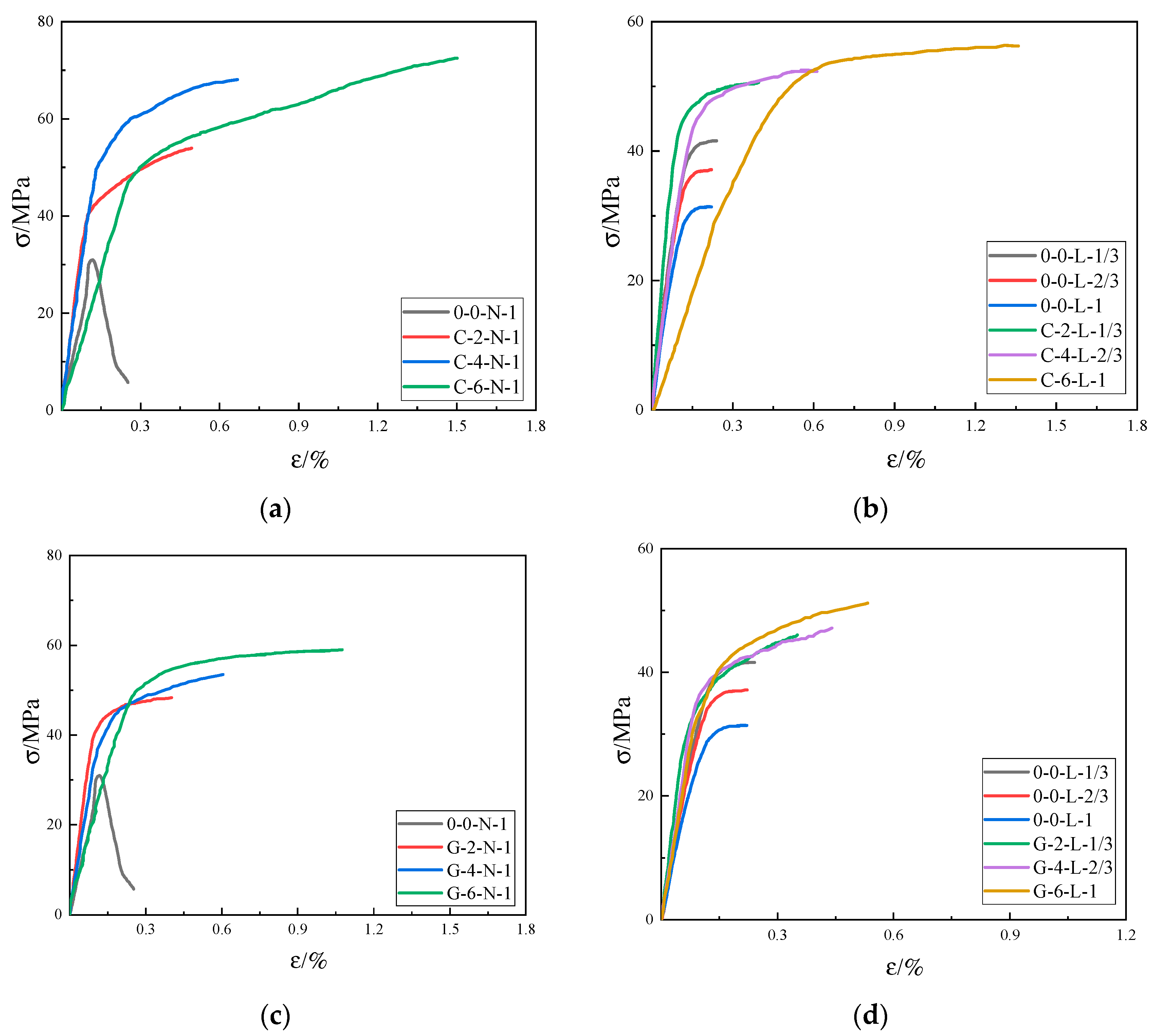
3.2.3. The Thickness of FRP

When the type of FRP and the content of lightweight aggregates are controlled to be consistent, the influences of the thickness of FRP on the compressive strength and peak compressive strain of FRP-AASLAC are shown in Figure 11, from which the following can be observed.
(1)
As for CFRP-AASLAC, when the number of FRP layers increased from 2 to 4, the compressive strength and peak compressive strain of the specimens increased by 26% and 36%. When the number of FRP layers increased from 4 to 6, the compressive strength and peak compressive strain of the specimens increased by 34% and 204%.
(2)
As for GFRP-AASLAC, when the number of FRP layers increased from 2 to 4, the compressive strength and peak compressive strain of the specimens increased by 11% and 51%. When the number of FRP layers increased from 4 to 6, the compressive strength and peak compressive strain of the specimens increased by 22% and 168%.
As the thickness of FRP increases, the restrained effect of FRP tube on the specimen is enhanced, so the bearing capacity and ductility of the specimen are significantly improved [67,68,69].

4. Revised Design-Oriented Stress–Strain Model

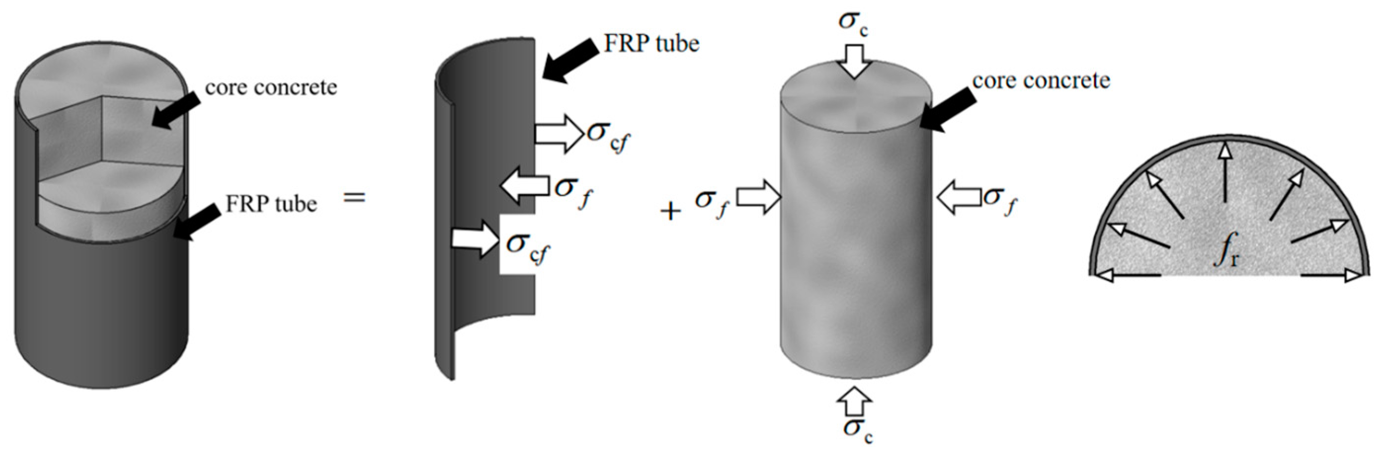
4.1. Judgement of Restrained Degree

The existing axial compressive constitutive models for FRP-confined concrete columns are mainly divided into two categories: (1) the parabolic model represented by THE Fardis and Khalili model [42], which is suitable for weakly confined concrete with post-peak weakened section and no secondary strengthened section; (2) the double broken line model represented by Lam and Teng [35], which is suitable for strongly confined concrete with the post-peak weakened section and the secondary strengthened section. To find the axial compressive constitutive model suitable for FRP tube-confined alkali-activated slag lightweight aggregate concrete columns, it is necessary to confirm the restrained degree of specimens. Different researchers put forward different strong and weak restrained indexes. For example, Teng proposed ρ = 2 t frp E frp / ( f co d ε c 0 ) . When ρ   ≥ 0.01, it is strongly confined concrete. When ρ < 0.01, it is weakly confined concrete, but the critical value is not suitable to high-strength concrete [70]. Mimiran proposed MCR = 2R f co /h f l . When MCR ≥ 0.15, it is strongly confined concrete, and when MCR < 0.15, it is weakly confined concrete [71].
The strongly and weakly restrained indexes of the specimens are listed in Table 7, and the judgement results show that all the tested specimens belong to the strongly confined concrete. In order to further confirm the restrained degrees of the specimens, the stress–strain curves of the specimens are shown in Figure 12. Combined with typical stress–strain curves of FRP-confined concrete circular columns in Figure 1, the tested specimens all conform to the basic characteristics of the strongly confined concrete. To sum up, the FRP tube-confined alkali-activated slag lightweight aggregate concrete columns studied in this paper belong to strongly confined concrete.

4.2. Models for the Compressive Strength and Peak Compressive Strain

At present, the ACI model [48] is the main calculated model applicable to the compressive strength and peak compressive strain of strongly confined concrete. The AASLAC is of poor toughness. This is similar to high-strength and ultra-high-strength concrete. It is worth studying if the design-oriented model of FRP-confined high-strength and ultra-high-strength concrete can be suitable to FRP-AASLAC. Liao’s model [72] exhibits remarkable performance in predicting the stress–strain curve and characteristic points of FRP-confined ultra-high-strength concrete of previous studies. Details of the two models are shown in Table 8.
The predictive results from the existing models of the compressive strength and peak compressive strain of FRP-AASLAC are shown in Figure 13 and Figure 14. Compared with the ACI model, the predictive results of f cc / f co and ε cc / ε co by Liao’s model are closer to the best fitting lines (Y = X), indicating that Liao’s model is more suitable for predicting the compressive strength and peak compressive strain of FRP-AASLAC.
Due to the material defects of alkali-activated slag lightweight aggregate concrete with a lower elastic modulus and larger shrinkage deformation, the predictive results of f cc / f co by Liao’s model are larger, while those of ε cc / ε co are smaller. To solve this problem, k1, k2, k3, k4, k5 and k6 were introduced to reflect the influences of material defects on the compressive strength and peak compressive strain of specimens based on the calculation formula of Liao’s model [35], which are shown in Table 9. Through fitting the experimental results, the revised models for the compressive strength and peak compressive strain are shown as Equations (1) and (2).
f cc f co = 1 + k 1 ( ε h , rup ε co ) k 2 ( f l f co ) k 3
ε cc ε co = 1 + k 4 ( f l f co ) k 5 ( ε h , rup ε co ) k 6
The predictive effects of the revised models for the compressive strength and peak compressive strain are shown in Figure 15. As can be seen from the figure, the predictive accuracies of the revised models for compressive strength and peak compressive strain are significantly improved. The regression coefficient of the predictive results and the test results for the compressive strength reached 0.9430, and the regression coefficient of the predictive results and the test results for the peak compressive strain reached 0.9160. The revised models can better predict the compressive strength and peak compressive strain of FRP-AASLAC.

4.3. Model for the Axial Compressive Constitutive Relationship

Although analysis-oriented models have advantages in accounting for the interaction between concrete and confining materials, the complexity of the incremental process prevents analysis-oriented models from direct use in design [35]. Compared to analysis-oriented models, design-oriented models are particularly suitable for direct application in design calculations. Liao’s models are the design-oriented axial compressive constitutive models [72]. The first segments of the models are parabolas, the second segments are straight lines, and the two segments for each model are smoothly connected. The slopes of the tangent lines at the origin point of the first parabolas are related to the elastic modulus of the core concrete. The intersection points of the second straight lines are extension lines and the vertical axis is usually the compressive strength of the core concrete, which is applicable to those specimens not experiencing stress reduction. The constitutive expressions of Liao’s models are shown in Equations (3)–(5).
σ c = { E c ε c ( E c E 2 ) 2 4 f co ε c 2 ;     ( 0 ε c ε t ) f co + E 2 ε c ; ( ε t ε c ε cu )
ε t = 2 f co E c E 2
E 2 = f cc f co ε cu
where f co   is the intersection point of the second straight line extension line and the vertical axis. The parabolic first portion meets the linear second portion with a smooth transition at ε t , and E2 is the slope of the linear second portion.
The lower elastic modulus and larger shrinkage deformation of alkali-activated slag lightweight aggregate concrete not only affect the compressive strength and peak compressive strain of the FRP tube-confined alkali-activated slag lightweight aggregate concrete column, but also make it uncertain for the axial compressive constitutive relationship of the FRP tube-confined alkali-activated slag lightweight aggregate concrete column. Therefore, based on the calculated formulas of Liao’s models [72], h1 and h2 are first introduced to revise the trend of the first parabola, then h3 is introduced to improve the slope of the second line, and finally h4 is introduced to improve the accuracy of the inflection point of the first parabola and the second line. Thus, the revised calculated formula can accurately reflect the axial compressive constitutive relationship of the FRP tube-confined alkali-activated slag lightweight aggregate concrete column. The revised model of the axial compressive constitutive relationship is shown in Equations (6)–(8).
σ c { h 1 E c ε c h 2 ( E c E 2 ) 2 4 f co ε c 2 ;     ( 0 ε c ε tr ) f co + E 2 ε c   ;   ( ε tr ε c ε cu )
ε tr = h 4 2 f co E c E 2
E 2 = h 3 f cc f co ε cu
where h 1 = 1.35 1.05 r ,   h 2 = 1.85 1.8 r ,   h 3 = 0.0076 ,   h 4 = 0.78 ,   r is the replacement rate of lightweight aggregate and ε tr and σ tr are the strain and stress at the inflection point of the two curves.
The comparisons between the revised models and test results of the FRP-AASLAC are shown in Figure 16. It can be seen from the figure that the revised model is highly similar to the stress–strain curve of the FRP-AASLAC for different groups. For the specimens filled with lightweight aggregate, alkali-activated slag lightweight aggregate concrete has material defects of lower elastic modulus and larger shrinkage deformation, so the inflection points of its curve lag behind the specimens filled with natural aggregate. The revised model considers the effect of the content of lightweight aggregate to eliminate material defects and better express the transition section. The predictive results show that the revised model has a shorter vertical distance and smaller errors from the test results. It is more suitable for predicting the axial compressive constitutive relationship of FRP-AASLAC.

5. Conclusions

In this paper, the effects of the type of FRP, the thickness of FRP and the content of lightweight aggregate on the axial compressive behaviours of FRP tube-confined alkali-activated slag lightweight aggregate concrete (FRP-AASLAC) columns are studied. The main conclusions can be drawn as follows.
(1)
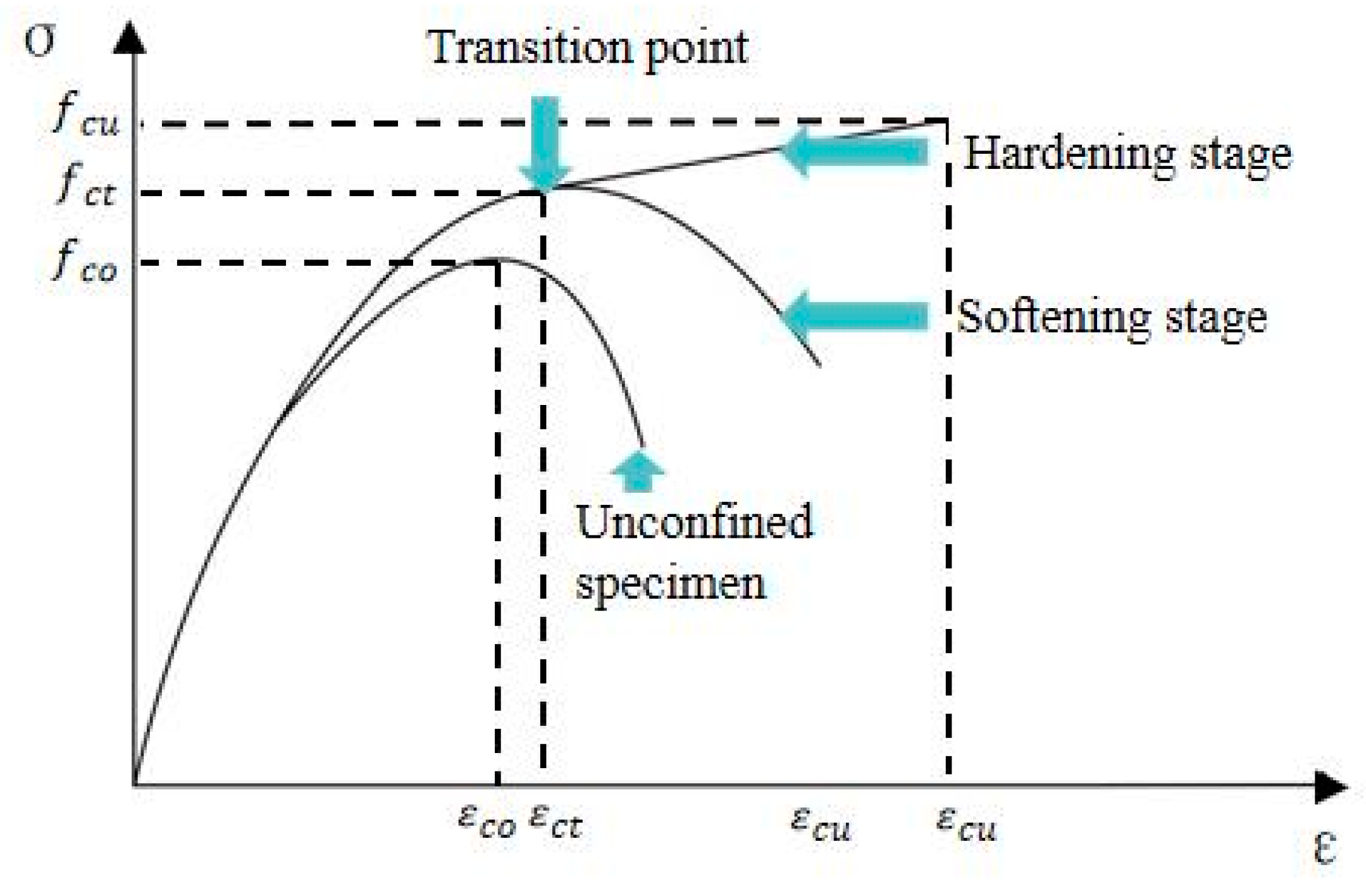
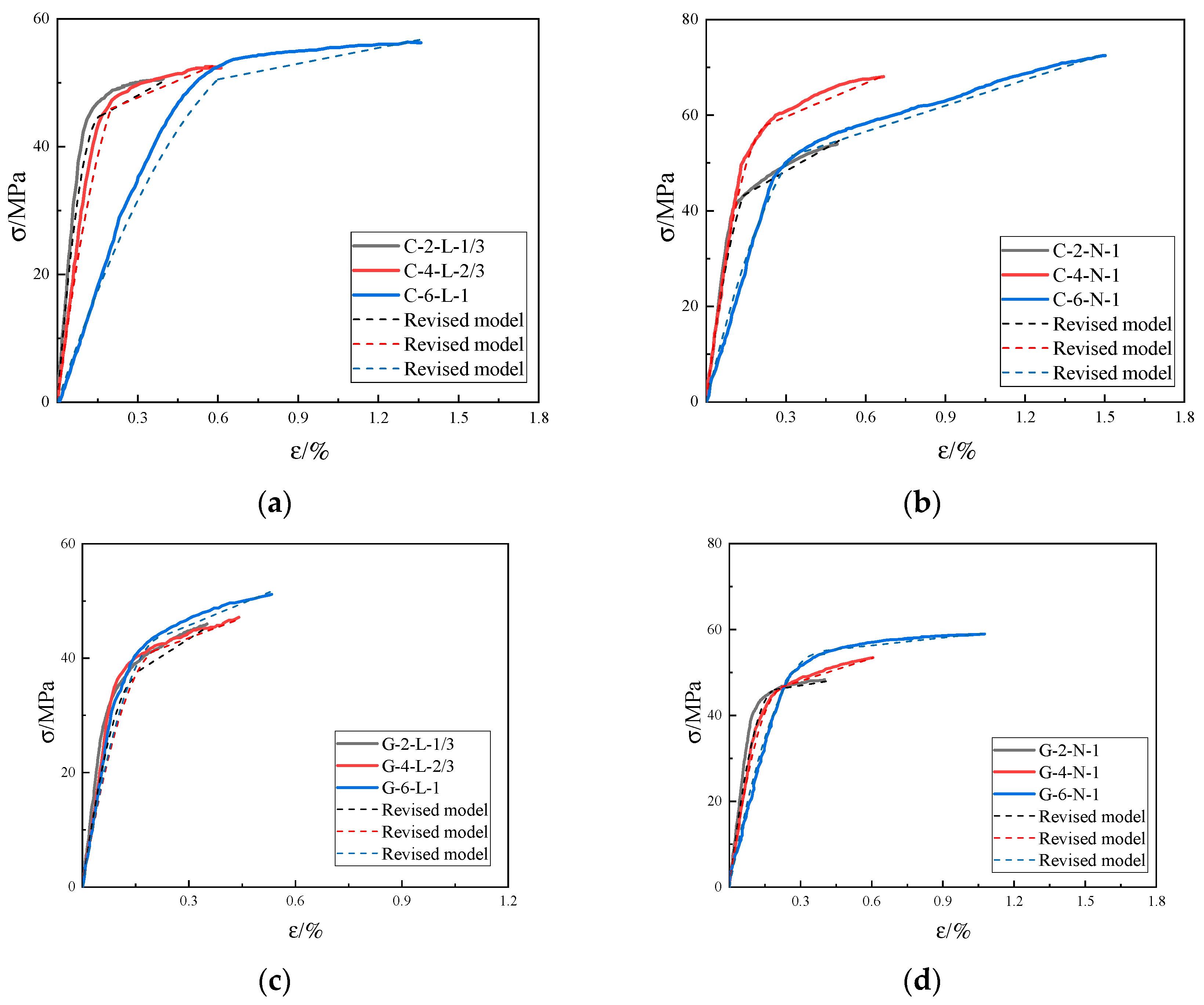
The constitutive relationship of FRP-AASLAC shows double broken line pattern without obvious softening section. The failure mode of FRP-AASLAC is the tensile rupture of the FRP tube near the column mid-height caused by the compressive expansion of core concrete.
(2)
The restraint effects of CFRP were higher than those of GFRP for the higher tensile strength and elastic modulus of CFRP. The compressive strength and peak compressive strain of GFRP-LAC were 79–90% and 72–90% of CFRP-AASLAC.
(3)
The restraint effects of FRP on lightweight aggregate concrete are higher than those on ordinary concrete. Compared with unrestrained specimens, the compressive strength and peak compressive strain of FRP-LAC filled with lightweight aggregate were improved by 80% and 560%, respectively, higher than those of FRP-LAC filled with natural aggregate with 60% and 490%, respectively.
(4)
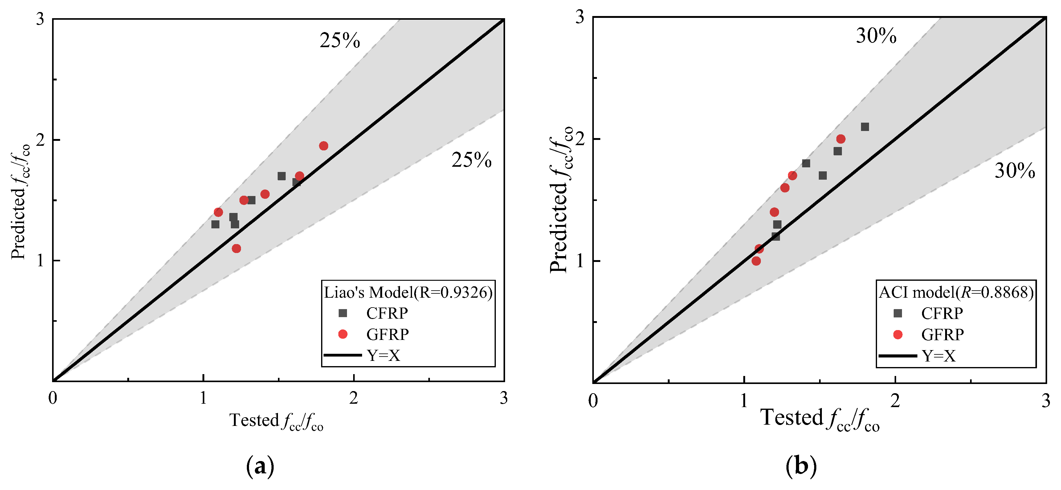
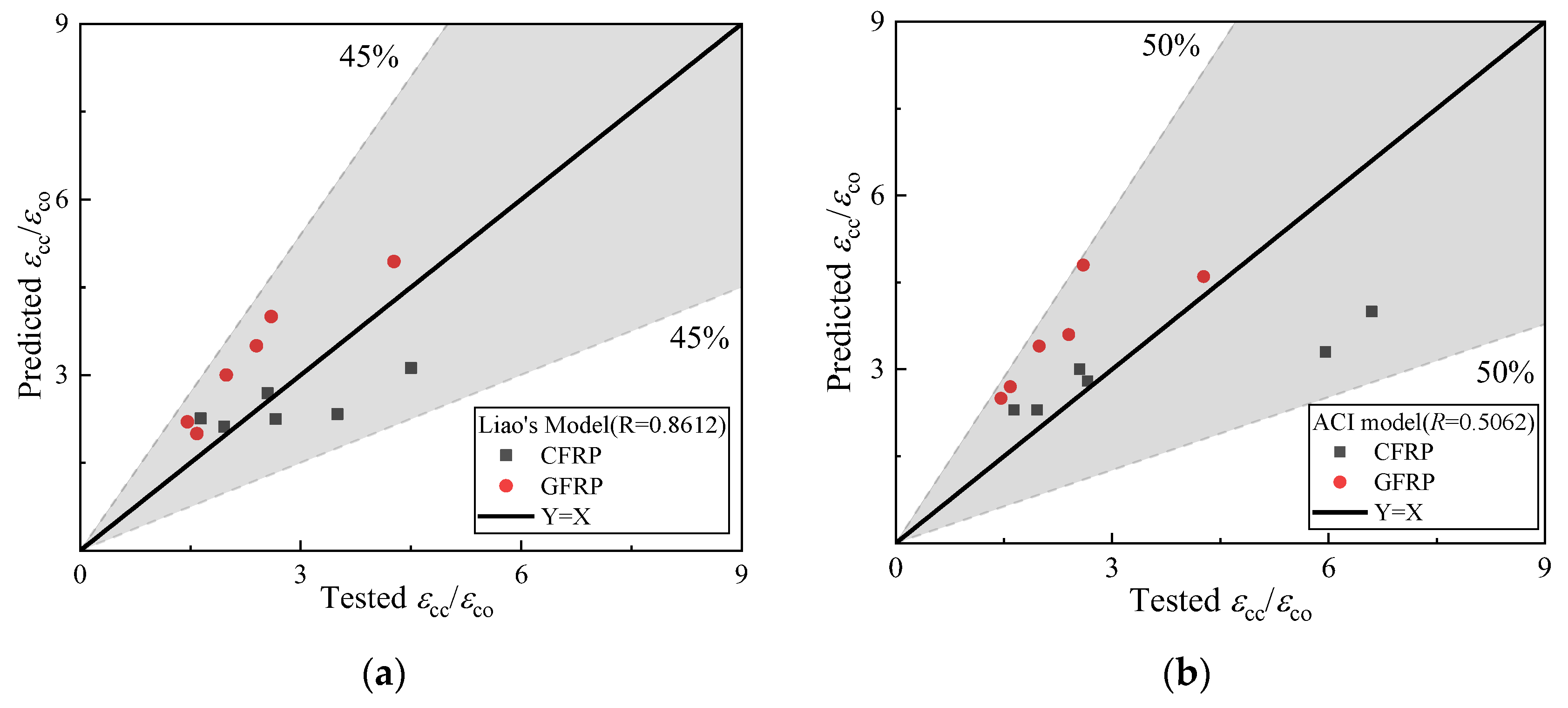
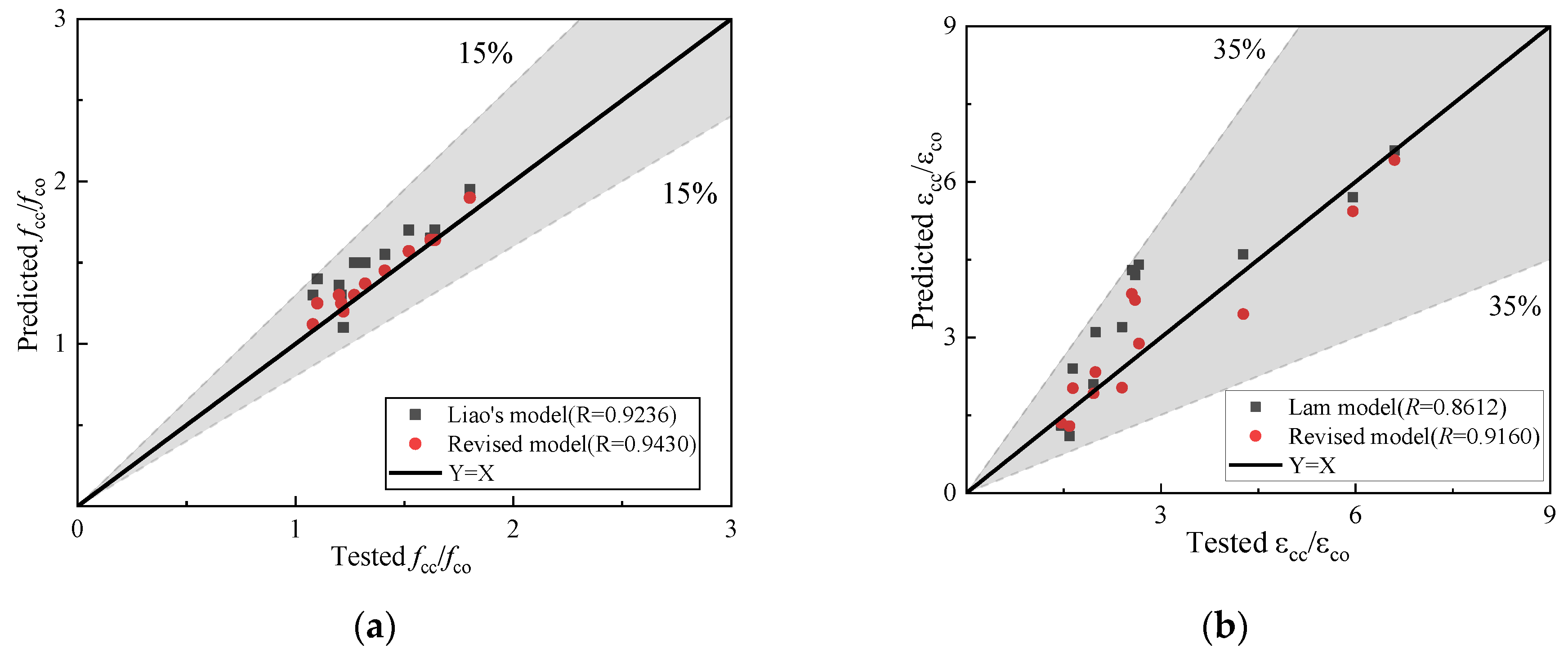
Comparisons between the existing models of FRP-confined concrete columns for the compressive strength and peak compressive strain and tested results were presented. The results show that the predictive accuracies of the existing models for the compressive strength were higher than those for the peak compressive strain, and the predictive accuracies of Liao’s models for the compressive strength and peak compressive strain were higher. Revised models of FRP-AASLAC for the compressive strength and peak compressive strain are proposed.
(5)
The revised model for the axial compressive constitutive relationship for FRP-AASLAC is proposed. In addition to the effects of compressive strength of core concrete, the type of FRP and its thickness, the revised model considers the effect of the content of lightweight aggregate, which can better express the transition section.
In order to promote the application of FRP-AASLAC, any limitations to the research should be considered.
(1)
Due to fabrication tolerances, load eccentricities and other adverse factors, most concrete columns are in a state of eccentric compression in practical engineering. This study focuses solely on investigating the axial mechanical performances of FRP-AASLAC, which are more relevant to real-world engineering scenarios. However, the investigation of its eccentric compression behaviours requires further research.
(2)
This study only investigated short concrete columns with a diameter of 150 mm and a height of 300 mm, without considering the influence of aspect ratios of the specimens. To broaden the engineering applications of FRP-AASLAC, further research is needed to examine the effects of aspect ratios and size-related phenomena on the axial mechanical performances of FRP-AASLAC.

Author Contributions

H.W. (Hui Wang) and X.Z. designed and wrote the paper; C.X., H.W. (Hao Wang), P.C. and L.Z. made comments and amendments to the paper. All authors have read and agreed to the published version of the manuscript.

Funding

The authors gratefully acknowledge the financial support of the Department of Transportation Science and Technology Projects in Hebei Province (Grant No. TH1-202020), the National Natural Science Foundation of China (Grant No. 52108132), the National Natural Science Foundation of China (Grant No. 52208148), the China Construction First Bureau (Group) Co., Ltd. for Technology Research and Development Platform Project (Grant No. PT-2022-10).

Data Availability Statement

Not applicable.

Conflicts of Interest

The authors declare no conflict of interest.

References

  1. Worrell, E.; Martin, N.; Price, L. Potentials for energy efficiency improvement in the US cement industry. Energy 2000, 25, 1189–1214. [Google Scholar] [CrossRef]
  2. Worrell, E.; Price, L.; Martin, N.; Hendriks, C.; Meida, L.O. Carbon dioxide emissions from the global cement industry. Annu. Rev. Energy Environ. 2001, 26, 303–329. [Google Scholar] [CrossRef]
  3. Khurana, S.; Banerjee, R.; Gaitonde, U. Energy balance and cogeneration for a cement plant. Appl. Therm. Eng. 2002, 22, 485–494. [Google Scholar] [CrossRef]
  4. Choate, W.T. Energy and Emission Reduction Opportunities for the Cement Industry; BCS Inc.: Laurel, MD, USA, 2003. [Google Scholar]
  5. Hu, S.; Jiang, Y.; Yan, D. China Building Energy Use and Carbon Emission Yearbook 2021: A Roadmap to Carbon Neutrality by 2060; Springer: Berlin/Heidelberg, Germany, 2022. (In Chinese) [Google Scholar]
  6. Jiao, Z.; Wang, Y.; Zheng, W.; Huang, W. Effect of the activator on the performance of alkali-activated slag mortars with pottery sand as fine aggregate. Constr. Build. Mater. 2019, 197, 83–90. [Google Scholar] [CrossRef]
  7. Zhang, Y.; Wan, X.M.; Yu, Q. Review of mechanical properties of alkali-excited cementitious materials. Concrete 2018, 3, 60–64. (In Chinese) [Google Scholar]
  8. Puertas, F.; Martínez Ramírez, S.; Alonso, S.; Vázquez, T. Alkali-activated fly ash/slag cements: Strength behaviour and hydration products. Cem. Concr. Res. 2000, 30, 1625–1632. [Google Scholar] [CrossRef]
  9. Escalante-Garcia, J.I.; Espinoza-Perez, L.J.; Gorokhovsky, A.; Gomez-Zamorano, L. Coarse blast furnace slag as a cementitious material, comparative study as a partial replacement of Portland cement and as an alkali activated cement. Constr. Build. Mater. 2009, 23, 2511–2517. [Google Scholar] [CrossRef]
  10. Hassanpour, M.; Shafigh, P.; Mahmud, H. Lightweight aggregate concrete fiber reinforcement–A review. Constr. Build. Mater. 2012, 37, 452–461. [Google Scholar] [CrossRef]
  11. Al-Khaiat, H.; Haque, M.N. Effect of initial curing on early strength and physical properties of a lightweight concrete. Cem. Concr. Res. 1998, 28, 859–866. [Google Scholar] [CrossRef]
  12. Uysal, H.; Demirboğa, R.; Şahin, R.; Gül, R. The effects of different cement dosages, slumps, and pumice aggregate ratios on the thermal conductivity and density of concrete. Cem. Concr. Res. 2004, 34, 845–848. [Google Scholar] [CrossRef]
  13. Bilodeau, A.; Kodur, V.K.R.; Hoff, G.C. Optimization of the type and amount of polypropylene fibres for preventing the spalling of lightweight concrete subjected to hydrocarbon fire. Cem. Concr. Compos. 2004, 26, 163–174. [Google Scholar] [CrossRef]
  14. Kayali, O.; Haque, M.N.; Zhu, B. Some characteristics of high strength fiber reinforced lightweight aggregate concrete. Cem. Concr. Compos. 2003, 25, 207–213. [Google Scholar] [CrossRef]
  15. Karthika, R.B.; Vidyapriya, V.; Sri, K.V.N.; Beaula, K.M.G.; Harini, R.; Sriram, M. Experimental study on lightweight concrete using pumice aggregate. Mater. Today Proc. 2021, 43, 1606–1613. [Google Scholar] [CrossRef]
  16. Jing, Q.; Wang, Y.; Chai, L.; Tang, C.-J.; Huang, X.-D.; Guo, H.; Wang, W.; You, W. Adsorption of copper ions on porous ceramsite prepared by diatomite and tungsten residue. Trans. Nonferrous Met. Soc. China 2018, 28, 1053–1060. [Google Scholar] [CrossRef]
  17. Liu, Y.; Du, F.; Yuan, L.; Zeng, H.; Kong, S. Production of lightweight ceramsite from iron ore tailings and its performance investigation in a biological aerated filter (BAF) reactor. J. Hazard. Mater. 2010, 178, 999–1006. [Google Scholar] [CrossRef]
  18. Ma, L.; Li, G.Z. The preparation of red mud lightweight ceramsite. In Advanced Materials Research; Trans Tech Publications Ltd.: Stafa-Zurich, Switzerland, 2013; Volume 648, pp. 96–99. [Google Scholar]
  19. Qin, J.; Yang, C.; Cui, C.; Huang, J.; Hussain, A.; Ma, H. Ca2+ and OH release of ceramsites containing anorthite and gehlenite prepared from waste lime mud. J. Environ. Sci. 2016, 47, 91–99. [Google Scholar] [CrossRef]
  20. Chen, P.; Shi, Z.; Cao, S.; Liu, P.; Rong, X.; Wang, L. Mechanical properties of alkali-activated slag lightweight aggregate concrete. J. Clean. Prod. 2022, 359, 132136. [Google Scholar] [CrossRef]
  21. Zheng, W.Z.; Zou, M.N.; Wang, Y. Research progress of alkali excited cementitious materials. J. Archit. Struct. 2018, 40, 28–39. (In Chinese) [Google Scholar]
  22. Mo, K.H.; Ling, T.C.; Alengaram, U.J.; Yap, S.P.; Yuen, C.W. Overview of supplementary cementitious materials usage in lightweight aggregate concrete. Constr. Build. Mater. 2017, 139, 403–418. [Google Scholar] [CrossRef]
  23. Toutanji, H.; Han, M.; Gilbert, J.; Matthys, S. Behavior of large-scale rectangular columns confined with FRP composites. J. Compos. Constr. 2010, 14, 62–71. [Google Scholar] [CrossRef]
  24. Richart, F.E.; Brandtzæg, A.; Brown, R.L. A Study of the Failure of Concrete under Combined Compressive Stresses; Engineering Experiment Station, College of Engineering, University of Illinois at Urbana Champaign: Champaign, IL, USA, 1928. [Google Scholar]
  25. Chastre, C.; Silva, M.A.G. Monotonic axial behavior and modelling of RC circular columns confined with CFRP. Eng. Struct. 2010, 32, 2268–2277. [Google Scholar] [CrossRef]
  26. Liang, M. Study on the Strength and Deformation Characteristics of CFRP Confined Concrete Cylinder; Dalian University of Technology: Dalian, China, 2012. (In Chinese) [Google Scholar]
  27. Hao, H.Y. Study on Mechanical Properties of FRP Tube Constrained Alkali Excitation-Recycled Aggregate Concrete Column; Southeast University: Nanjing, China, 2019. (In Chinese) [Google Scholar]
  28. Zohrevand, P.; Mirmiran, A. Behavior of ultrahigh-performance concrete confined by fiber-reinforced polymers. J. Mater. Civ. Eng. 2011, 23, 1727–1734. [Google Scholar] [CrossRef]
  29. Liao, J.J.; Yang, K.Y.; Zeng, J.J.; Quach, W.M.; Ye, Y.Y.; Zhang, L. Compressive behavior of FRP-confined ultra-high performance concrete (UHPC) in circular columns. Eng. Struct. 2021, 249, 113246. [Google Scholar] [CrossRef]
  30. Eid, R.; Paultre, P. Compressive behavior of FRP-confined reinforced concrete columns. Eng. Struct. 2017, 132, 518–530. [Google Scholar] [CrossRef]
  31. Wang, W.; Sheikh, M.N.; Hadi, M.N.S.; Gao, D.; Chen, G. Behaviour of concrete-encased concrete-filled FRP tube (CCFT) columns under axial compression. Eng. Struct. 2017, 147, 256–268. [Google Scholar] [CrossRef]
  32. Guo, Y.C.; Gao, W.Y.; Zeng, J.J.; Duan, Z.-J.; Ni, X.-Y.; Peng, K.-D. Compressive behavior of FRP ring-confined concrete in circular columns: Effects of specimen size and a new design-oriented stress-strain model. Constr. Build. Mater. 2019, 201, 350–368. [Google Scholar] [CrossRef]
  33. Parvin, A.; Jamwai, A.S. Performance of externally FRP reinforced columns for changes in angleand thickness of the wrap and concrete strength. Compos. Struct. 2006, 73, 451–457. [Google Scholar] [CrossRef]
  34. Pan, J.L.; Xu, T.; Hu, Z.J. Experimental investigation of load carrying capacity of the slender reinforced concrete columns wrapped with FRP. Constr. Build. Mater. 2007, 22, 1991–1996. [Google Scholar] [CrossRef]
  35. Xing, L.; Lin, G.; Chen, J.F. Behavior of FRP-confined circular RC columns under eccentric compression. J. Compos. Constr. 2020, 24, 04020030. [Google Scholar] [CrossRef]
  36. Silva, M.A.G. Aging of GFRP laminates and confinement of concrete columns. Compos. Struct. 2007, 79, 97–106. [Google Scholar] [CrossRef]
  37. Wang, Z.; Li, Z.; Yang, J.Q.; Huang, F.; Feng, P. Axial compressive and seismic performance of GFRP wrapped square RC columns with different scales. J. Build. Eng. 2022, 62, 105342. [Google Scholar] [CrossRef]
  38. Gu, D.S.; Wu, G.; Wu, Z.S.; Wu, Y.-F. Confinement effectiveness of FRP in retrofitting circular concrete columns under simulated seismic load. J. Compos. Constr. 2010, 14, 531–540. [Google Scholar] [CrossRef]
  39. Zheng, B.T.; Teng, J.G. Finite-element modeling of FRP-confined noncircular concrete columns using the evolutionary potential-surface trace plasticity constitutive model for concrete. J. Compos. Constr. 2023, 27, 04022089. [Google Scholar] [CrossRef]
  40. Ali, O.; Abbas, A.; Khalil, E.; Madkour, H. Numerical investigation of FRP-confined short square RC columns. Constr. Build. Mater. 2021, 275, 122141. [Google Scholar] [CrossRef]
  41. Zeng, J.J.; Chen, S.P.; Zhuge, Y.; Gao, W.-Y.; Duan, Z.-J.; Guo, Y.-C. Three-dimensional finite element modeling and theoretical analysis of concrete confined with FRP rings. Eng. Struct. 2021, 234, 111966. [Google Scholar] [CrossRef]
  42. Fardis, M.N.; Khalili, H.H. FRP-encased concrete as a structural material. Mag. Concr. Res. 1982, 34, 191–202. [Google Scholar] [CrossRef]
  43. Samaan, M.; Mirmiran, A.; Shahawy, M. Model of concrete confined by fiber composites. J. Struct. Eng. 1998, 124, 1025. [Google Scholar] [CrossRef]
  44. Youssef, M.N.; Feng, M.Q.; Mosallam, A.S. Stress–strain model for concrete confined by FRP composites. Compos. Part B Eng. 2007, 38, 614–628. [Google Scholar] [CrossRef]
  45. Wei, Y.Y.; Wu, Y.F. Unified stress–strain model of concrete for FRP-confined columns. Constr. Build. Mater. 2012, 26, 381–392. [Google Scholar] [CrossRef]
  46. Mander, J.B.; Priestley, M.J.N. Theoretical stress-strain model for confined concrete. J. Struct. Eng. 1988, 114, 1804. [Google Scholar] [CrossRef]
  47. Saadatmanesh, H.; Ehsani, M.R.; Li, M.W. Strength and ductility of concrete columns externally reinforced with fiber composite straps. Struct. J. 1994, 91, 434–447. [Google Scholar]
  48. ACI 440.2R-02; Guide for the Design and Construction of Externally Bonded FRP Systems for Strengthening Concrete Structures. American Concrete Institute: Indianapolis, IN, USA, 2002.
  49. Fu, Y.W.; Cai, L.C.; Cao, D.G.; Wu, Y.G. Study on preparation and properties of alkali mineral powder inorganic polymer concrete. J. Build. Mater. 2010, 13, 524–528. (In Chinese) [Google Scholar]
  50. Xie, T.; Ozbakkaloglu, T. Behavior of low-calcium fly and bottom ash-based geopolymer concrete cured at ambient temperature. Ceram. Int. 2015, 41, 5945–5958. [Google Scholar] [CrossRef]
  51. Krizan, D.; Zivanovic, B. Effects of dosage and modulus of water glass on early hydration of alkali–slag cements. Cem. Concr. Res. 2002, 32, 1181–1188. [Google Scholar] [CrossRef]
  52. Liu, X.; Wu, T.; Liu, Y. Stress-strain relationship for plain and fibre-reinforced lightweight aggregate concrete. Constr. Build. Mater. 2019, 225, 256–272. [Google Scholar] [CrossRef]
  53. Roufael, G.; Beaucour, A.L.; Eslami, J.; Hoxha, D.; Noumowé, A. Influence of lightweight aggregates on the physical and mechanical residual properties of concrete subjected to high temperatures. Constr. Build. Mater. 2021, 268, 121221. [Google Scholar] [CrossRef]
  54. Zhang, M.H.; Gjvorv, O.E. Mechanical properties of high-strength lightweight concrete. Mater. J. 1991, 88, 240–247. [Google Scholar]
  55. GB/T 50081-2002; Standard of Test Methods for Mechanical Properties of Ordinary Concrete. China Architecture & Building Press: Beijing, China, 2002. (In Chinese)
  56. Gao, S.; Zhao, G.; Guo, L.; Zhou, L.; Yuan, K. Utilization of coal gangue as coarse aggregates in structural concrete. Constr. Build. Mater. 2021, 268, 121212. [Google Scholar] [CrossRef]
  57. Tamai, H. Enhancing the performance of porous concrete by utilizing the pumice aggregate. Procedia Eng. 2015, 125, 732–738. [Google Scholar]
  58. Liu, X.M. Experimental Study and Analysis of Axial Compression Performance of Light Aggregate Concrete Restrained by CFRP; Shenzhen University: Shenzhen, China, 2016. (In Chinese) [Google Scholar]
  59. Chen, L.; Ozbakkaloglu, T. Corner strengthening of square and rectangular concrete-filled FRP tubes. Eng. Struct. 2016, 117, 486–495. [Google Scholar] [CrossRef]
  60. Shen, Y. Compressive Properties of CFRP Confined Steel Fiber Reinforced Concrete Cylindrical Shaft; Xi’an University of Architecture and Technology: Xi’an, China, 2018. (In Chinese) [Google Scholar]
  61. Guo, Y.C.; Xiao, S.H.; Zeng, J.J.; Su, J.-Y.; Li, T.-Z.; Xie, Z.-H. Behavior of concrete-filled FRP tube columns internally reinforced with FRP-steel composite bars under axial compression. Constr. Build. Mater. 2022, 315, 125714. [Google Scholar] [CrossRef]
  62. Zeng, J.J.; Gao, W.Y.; Duan, Z.J.; Bai, Y.-L.; Guo, Y.-C.; Ouyang, L.-J. Axial compressive behavior of polyethylene terephthalate/carbon FRP-confined seawater sea-sand concrete in circular columns. Constr. Build. Mater. 2020, 234, 117383. [Google Scholar] [CrossRef]
  63. Watanabe, K.; Nakamura, R.; Honda, Y.; Toyoshima, M.; Fujimaki, T. Confinement effect of FRP sheet on strength and ductility of concrete cylinders under uniaxial compression. In Proceedings of the Third International Symposium on Non-Metallic Reinforcement for Concrete Structures, Sapporo, Japan, 14–16 October 1997. [Google Scholar]
  64. Lim, J.C.; Ozbakkloglu, T. Factors influencing hoop rupture strains of FRP-confined concrete. Appl. Mech. Mater. 2014, 501, 949–953. [Google Scholar] [CrossRef]
  65. Almusallam, T.H. Behavior of normal and high-strength concrete cylinders confined with E-glass/epoxy composite laminates. Compos. Part B 2006, 38, 629–639. [Google Scholar] [CrossRef]
  66. Berthet, J.F.; Ferrier, E.; Hamelin, P. Compressive behavior of concrete externally confined by composite jackets: Part A: Experimental study. J. Constr. Build. Mater. 2005, 19, 223–232. [Google Scholar] [CrossRef]
  67. Matthys, S.; Toutanji, H.; Taerwe, L. Stress-strain behavior of large-scale circular columns confined with FRP composites. Struct. Eng. 2006, 132, 123. [Google Scholar] [CrossRef]
  68. Sadeghian, P.; Rahai, A.R.; Ehsani, M.R. Experimental study of rectangular RC columns strengthened with CFRP composites under eccentric loading. J. Compos. Constr. 2010, 14, 443–450. [Google Scholar] [CrossRef]
  69. Wang, L.M.; Wu, Y.F. Effect of corner radius on the performance of CFRP-confined square concrete columns: Test. Eng. Struct. 2007, 30, 493–505. [Google Scholar] [CrossRef]
  70. Teng, J.G.; Jiang, T.; Lam, L.; Luo, Y.Z. Refinement of a design-oriented stress-strain model for FRP-confined concrete. J. Compos. Constr. 2009, 13, 269. [Google Scholar] [CrossRef]
  71. Mirmiran, A.; Shahawy, M.; Samaan, M.; Echary, H. Effect of column parameters on FRP-confined concrete. J. Compos. Constr. ASCE 1998, 2, 175–185. [Google Scholar] [CrossRef]
  72. Liao, J.J.; Zeng, J.J.; Gong, Q.M.; Quach, W.M.; Gao, W.Y.; Zhang, L. Design-oriented stress-strain model for FRP-confined ultra-high performance concrete (UHPC). Constr. Build. Mater. 2022, 318, 126200. [Google Scholar] [CrossRef]
Figure 1. Typical stress–strain curves of FRP-confined concrete circular columns.
Buildings 13 02284 g001
Figure 2. FRP tubes. (a) CFRP tube; (b) GFRP tube.
Buildings 13 02284 g002
Figure 3. Flow chart of specimen preparation: (a) weighing the materials; (b) mixing the materials; (c) preparing the alkali-activator; (d) preparing the AASLAC; (e) pouring the AASLAC; (f) preparing the test.
Buildings 13 02284 g003
Figure 4. FRP tube-confined alkali-activated slag lightweight aggregate concrete column.
Buildings 13 02284 g004
Figure 5. Test devices: (a) loading devices; (b) measuring points.
Buildings 13 02284 g005
Figure 6. Failure modes of AASLAC: (a) 0-0-N-1; (b) 0-0-L-1/3; (c) 0-0-L-2/3; (d) 0-0-L-1.
Buildings 13 02284 g006
Figure 7. Failure modes of CFRP-AASLAC: (a) C-2-N-1; (b) C-4-N-1; (c) C-6-N-1; (d) C-2-L-1/3; (e) C-4-L-2/3; (f) C-6-L-1.
Buildings 13 02284 g007
Figure 8. Failure modes of GFRP-AASLAC: (a) G-2-N-1; (b) G-4-N-1; (c) G-6-N-1; (d) G-2-L-1/3; (e) G-4-L-2/3; (f) G-6-L-1.
Buildings 13 02284 g008
Figure 9. Influences of the lightweight aggregate content on the compressive strength and peak compressive strain: (a) influence for content of lightweight aggregate on the compressive strength; (b) influence for content of lightweight aggregate on the peak compressive strain.
Buildings 13 02284 g009
Figure 10. Influences of the FRP type on the compressive strength and peak compressive strain: (a) influence of FRP type on the com-pressive strength; (b) influence of FRP type on the peak compressive strain.
Buildings 13 02284 g010
Figure 11. Influences of the FRP thickness on the compressive strength and peak compressive strain: (a) influence of FRP thickness on the compressive strength; (b) influence of FRP thickness on the peak compressive strain.
Buildings 13 02284 g011
Figure 12. The stress–strain curves of the specimens for different groups: (a) group 1; (b) group 2; (c) group 3; (d) group 4.
Buildings 13 02284 g012
Figure 13. The predictive results of the existing models on the compressive strength of specimens: (a) Liao’s model; (b) ACI model.
Buildings 13 02284 g013
Figure 14. The predictive results of the existing models on the peak compressive strain of specimens: (a) Liao’s model; (b) ACI model.
Buildings 13 02284 g014
Figure 15. The predictive effects of the revised models: (a) the predictive effect of the compressive strength; (b) the predictive effect of the peak compressive strain.
Buildings 13 02284 g015
Figure 16. Comparisons of the revised models and tested results: (a) group 1; (b) group 2; (c) group 3; (d) group 4.
Buildings 13 02284 g016
Table 1. Research status of FRP-confined concrete in detail.
ResearchersContentsParametersRemarks
Eid [30]Axial compressive behaviours of RC columns confined by FRPMechanical and geometrical properties of the concrete and FRPThis paper presents a unified stress–strain model suitable to represent the compressive behaviours of circular and square/rectangular reinforced concrete columns confined internally with TSR and/or externally with FRP.
Wang [31]Axial compressive behaviours of concrete columns confined by FRP tubesFRP thicknessThe parametric analyses showed that by increasing the inner and outer concrete strengths, the first peak loads of the columns could increase. The ultimate axial loads could significantly increase by increasing the inner concrete compressive strength. The FRP tube thickness and the filament winding angle significantly influences the ultimate loads and ultimate axial strains of the columns.
Guo [32]Axial compressive behaviours of concrete columns confined by FRPDifferent scales, and degrees of FRP wrappingSimilar to the fully wrapped columns, the partially wrapped columns failed due to the tensile rupture of FRP strips. The axial strains and the hoop strains at the mid-plane of the concrete between two adjacent FRP rings were larger than those in the FRP rings, regardless of the sizes of the tested specimens.
Parvin [33,34]Axial compressive behaviours of concrete columns confined by CFRP sheetWinding angle and
layer of FRP
The restrained effect was better when the compressive direction and winding direction are along 90° and 45°. The bearing capacity and ductility of specimens were positively correlated with the thickness of CFRP sheets.
Xing [35]Eccentric compressive behaviours of RC columns confined by FRPFRP thickness, initial load eccentricity, and
column slenderness
The ultimate axial load of an eccentrically loaded FRP-confined circular RC column decreased rapidly as the load eccentricity or the column slenderness increased. In the post-peak stage, the axial load decreased more gradually in a column with a larger load eccentricity or a larger column slenderness. The design equations in both the Chinese national standard and the UK design guidance predicted the test results well, with the latter providing slightly more conservative predictions.
Silva [36]Durability behaviours of concrete columns confined by GFRPType of FRPAt low temperatures, GFRP-confined concrete could resist the damage caused by freezing expansion of pore water in concrete and improve the strength of specimens. The strength of GFRP-confined concrete decreased only by 2–16% after 300 freeze-thaw cycles, and the failure modes of the specimens after 150 freeze-thaw cycles were compared without constraints. The corrosion resistance of GFRP-confined concrete was improved obviously. The fire resistance limit of GFRP-confined concrete could reach 4 h.
Wang [37]Seismic behaviours of reinforced concrete columns confined by GFRPDifferent scalesWith the increasing column scales but the constant volumetric ratio of FRP wraps, the improvement of load bearing capacity reduced significantly, while the ductility and other seismic performances such as energy dissipation capacity and equivalent viscous damping ratio could still be enhanced. With an increasing axial compression ratio (from 0.35 to 0.65), the lateral load-bearing capacity of the FRP wrapped columns increased while the ductility factor dropped significantly.
Gu [38]Seismic behaviours of reinforced concrete columns confined by FRPType and layer of FRPThe horizontal deformation capacity of the component was positively correlated with the FRP thickness, negatively correlated with the axial compression ratio, and not correlated with the FRP fracture strain. The FRP-onfined stiffness had an important effect on the energy dissipation capacity of the component and the thickness of FRP had an important effect on the size of the plastic hinge area of the component.
Zheng [39]Finite element analysis on noncircular concrete columns confined by FRP/A viscoplastic regularization with a fixed value equal to 0.0005 could provide accurate behaviour. Nevertheless, the dilation angle could not be considered as a fixed value and should be related to the confinement degree coefficient Cd, which depends on the cross-sectional geometrical and FRP properties. Among the four considered design codes, ACI-440 and ECP-208 provided more accurate behaviours than CSA-S806 and FIB-Bulletin-14.
Ali [40]Finite element analysis on short square RC columns confined by FRP/The paper calibrated the concrete dilatancy angle and viscoplastic regularization parameters in the CDP model for the applications of square RC columns confined with FRP sheets. Effective strain values of 0.55 εfrp and 0.004 were recommended to enhance the performance of the FIB and CSA codes, respectively.
Zeng [41]Finite element analysis on concrete columns confined by FRP/The stress distribution at the centre level of two adjacent FRP rings/ties was obtained, and the relationship between the arching action angle and controlling parameters (i.e., unconfined concrete strength, FRP width, FRP thickness and clear spacing of FRP rings) was established based on a proposed theoretical model of the arching action angle.
Table 2. Material properties of the FRP tubes.
FRP TypesElastic Modulus Efrp (GPa)Tensile Strength ffrp (Mpa)Elongation
(%)
Layer Thickness (mm)
CFRP23645071.850.15
GFRP7626503.50.18
Table 3. Chemical composition of granulated blast furnace slag.
CompositionCaOSiO2Al2O3MgOFe2O3Others
Content/%41.1733.9413.167.280.663.79
Table 4. Physical properties of coarse aggregate.
Coarse
Aggregate Types
Packing Density (kg/m3)Density
Degree
Cylinder
Compressive Strength (Mpa)
Water
Absorption Rate of 1 h (%)
Softening
Coefficient
Rate of Mud Content (%)Rate of Boiling Loss (%)
Fly ash aggregate65087712.111.00.851.62.4
Table 5. Detailed mix design of the specimens.
GroupFRP TypeFRP LayerAggregate TypeContentfco
(Mpa)
εco
( 10 3   μ ε )
fcc
(Mpa)
εcc
( 10 3   μ ε )
f c c f c o ε c c ε c o
0-0-N-1-0NA044.72521----
0-0-L-1/3-0FA1/341.52406----
0-0-L-2/3-0FA2/337.12215----
0-0-L-1-0FA100%31.12053----
C-2-N-1CFRP2NA044.7252153.9 49331.21 1.96
C-4-N-1CFRP4NA044.7252167.9 66961.52 2.66
C-6-N-1CFRP6NA044.7252172.4 15,0131.62 5.96
G-2-N-1GFRP2NA044.7252148.340161.08 1.59
G-4-N-1GFRP4NA044.7252153.6 60491.20 2.40
G-6-N-1GFRP6NA044.7252159.1 10,7531.32 4.27
C-2-L-1/3CFRP2FA1/341.5240650.639551.22 1.64
C-4-L-2/3CFRP4FA2/337.1221552.356551.41 2.55
C-6-L-1CFRP6FA100%31.1205356.1 13,5461.80 6.60
G-2-L-1/3GFRP2FA1/341.5240645.635131.10 1.46
G-4-L-2/3GFRP4FA2/337.1221547.344041.27 1.99
G-6-L-1GFRP6FA100%31.1205351.153331.64 2.60
Note: The single-layer thickness of the CFRP tube is 0.15 mm, and the single-layer thickness of the GFRP tube is 0.18 mm; f co , compressive strength of AASLAC (Mpa); ε co , strain corresponding to compressive strength of AASLAC ( μ ε ); f cc , compressive strength of FRP-AASLAC (Mpa); ε cc ; strain corresponding to the compressive strength of FRP-AASLAC ( μ ε ); NA, natural aggregate; FA, fly ash aggregate.
Table 6. Concrete mix proportions.
CompoundWaterNaOHNa2SiO3SlagRiver SandNatural Aggregate
Concentration, kg/m315227.81646258331320
Note: The mix proportions are suitable for natural aggregate. Lightweight aggregate needs to replace natural coarse aggregate with equal volume substitution.
Table 7. The strong and weak restrained indexes of the specimens.
GroupρMCRJudgement of Restrained Degree
C-2-N-10.0531.240Strongly confined concrete
C-4-N-10.1060.620
C-6-N-10.1600.413
G-2-N-10.0211.757
G-4-N-10.0410.879
G-6-N-10.0620.586
C-2-L-1/30.0651.151
C-4-L-2/30.1630.514
C-6-L-10.3230.288
G-2-L-1/30.0251.631
G-4-L-2/30.0630.729
G-6-L-10.1250.407
Table 8. Details of the existing models for the compressive strength and peak compressive strain.
ModelsEquations for the Compressive StrengthEquations for the Peak Compressive StrainRemarks
Liao [72] f cc f co = 1 + 0.606 ( ε h , rup ε co ) 0.7 ( f l f co ) 0.6     ε cc ε co = 1 + 0.595 ( f l f co ) 0.1 ( ε h , rup ε co ) 1.45 ε h , rup = 0.64 ε frp
ACI [48] f cc f co = 2.25 1 + 7.9 f l f co 2 f l f co 1.25 ε cc ε co = 1.71 ( 5 f cc 4 f co ) E c A c f l = 2 f frp t frp D = 2 ε frp E frp t frp D
Note: f cc   is the compressive strength of FRP tube-confined concrete columns (MPa); f co   is the compressive strength of core concrete (MPa); ε cc is the strain corresponding to the compressive strength of FRP tube-confined concrete columns (με); ε co   is the strain corresponding to the compressive strength of core concrete (με); f frp is the tensile strength of FRP (MPa); E frp is the elastic modulus of FRP (GPa); D is the section diameter of the specimen (mm); h is the height of the specimen (mm); f l is the lateral constraint stress provided by FRP (MPa).
Table 9. Details of the correction factors.
FRP Typek1k2k3k4k5k6
CFRP0.40.700.500.450.051.00
GFRP0.40.700.450.350.050.90
Disclaimer/Publisher’s Note: The statements, opinions and data contained in all publications are solely those of the individual author(s) and contributor(s) and not of MDPI and/or the editor(s). MDPI and/or the editor(s) disclaim responsibility for any injury to people or property resulting from any ideas, methods, instructions or products referred to in the content.

