Article

Optimal Cable Force Adjustment for Long-Span Concrete-Filled Steel Tube Arch Bridges: Real-Time Correction and Reliable Results

1
Guangxi Transportation Science and Technology Group Co., Ltd., Nanning 530007, China
2
College of Civil Engineering and Architecture, Guangxi University, Nanning 530004, China
3
Guangxi Beitou Traffic Maintenance Technology Group Co., Ltd., Nanning 530029, China
*
Author to whom correspondence should be addressed.
Buildings 2023, 13(9), 2214; https://doi.org/10.3390/buildings13092214
Submission received: 8 July 2023 / Revised: 19 August 2023 / Accepted: 28 August 2023 / Published: 30 August 2023

Abstract

:
For complex structures, the existing optimization method for suspender cable forces involves extensive matrix operations during the solution process, requiring high computational power and time. As a result, obtaining a more accurate solution becomes challenging. To address this issue and improve the stress distribution of suspenders in the completed state, while minimizing the need for frequent cable force adjustments and grid beam elevation changes during construction, a novel method for cable force optimization is proposed. In this study, the Pingnan Third Bridge, which is the world’s longest large span arch bridge with a span of 575 m, is taken as the engineering background. This study combines finite element analysis and multi-objective optimization methods to develop a cable force optimization approach for real-time correction during the panel girder lifting of long-span concrete-filled steel tube (CFST) arch bridges. The optimization method involves treating the panel girder weight and displacement during construction as parameter variables, and considering the displacement and unevenness of the panel girder in the completed state as constraint conditions. The objective equation is defined based on the displacement and cable force during the lifting construction process and, through optimization, the cable forces and displacements of each lifting section are calculated. The results demonstrate the feasibility of integrating optimization theory into the cable force optimization process during panel girder lifting. In this study, we have taken into account the characteristics of real-world engineering and focused on specific key points to reduce the order of the influence matrix. Consequently, the computational costs are reduced, facilitating the development of a multi-objective tension optimization program. By minimizing segment displacement variations and ensuring even cable force distribution in the completed state, the method ensures that the bridge meets the required completion requirements without the need for repetitive iterations or cumbersome calculations. It provides higher optimization efficiency and superior outcomes, offering significant value for cable force calculations during suspender construction of similar bridge types and guiding construction processes.

1. Introduction

Long-span CFST arch bridges are becoming more and more preferred for their low cost, fast construction, reasonable force, durability, and they are inexpensive to maintain [1,2,3]. China ranks first in constructing CFST arch bridges, as around 500 bridges have been built within less than 30 years since this technology was born and 70 of those bridges are more than 200 m [4,5,6]. The CFST bridge made a large step forward when advanced technologies were applied in bridge construction [7]. After the completion of the Chongqing Wushan Yangtze River Bridge, with a span of 460 m, and that of the 530 m Sichuan Hejiang Yangtze River Bridge, both located in south-west Chin, the construction of the Pingnan Third Bridge began, whose span is 575 m, which set a new world record again. New requirements for construction technologies, techniques, control theories, and calculation methods are needed each time that the span of large-span CFST arch bridges increases. In the past, the computation optimization of cable forces in large-span bridges was usually conducted using the influence matrix method. The influence matrix method is a commonly used structural optimization approach. However, for complex structures, the solution process of the influence matrix method requires a significant amount of matrix operations, demanding high computational power and time.
The way to determine the initial tension of a suspender is similar to that of cable stayed bridges. In China, the forward iteration method [8,9,10], the backward analysis method (Kegui Xin 2004), the minimum bending energy method [11,12,13,14], the influence matrix method [15,16], the rigid suspender method [17,18], as well as the difference iteration method [19], are commonly adopted. While the forward iteration method needs cumbersome calculations, constrained by convergence conditions, it is partially non-convergent. Geometric nonlinearity, shrinkage and creep, and other constraints are not considered in the backward analysis method and the structural internal force does not close. As for the minimum bending energy method, which takes effect on the finished bridge state, it does not take the construction process into consideration, thus it can only be applied to dead load cable force optimization. The influence matrix method is widely used, which has lower accuracy and a short suspender cable force has high heterogeneity. The difference iteration method is based on the forward iteration method, merely reducing the number of convergences. By combining the difference iteration method with the influence matrix, Yang Xuan [20] achieved the speeding up of the equation convergence, which then decreased the calculation. Nakayama [21] applied multi-target optimization to cable-stayed bridge construction control. Before the arch rib closure, Zhang Zhicheng et al. [22] thought that the minimum sum of the squares of the deviation from the control point could be established as the cable force optimization objective. However, none of the methods mentioned above consider the state variable during construction. During cable-stay buckling and arch rib lifting, Hang Yu [23] and Du Hailong [24] proposed the idea of optimal processes and controllable results for calculating the cable force and arch rib deformation when assembling arch ribs. Jie Dai [25] suggested that the main direction for development in this field is the coupled optimization problem of reasonable bridge construction status and reasonable construction status, along with the embedded fusion of optimization algorithms and finite element programs. Yulin Zhan [26] proposed an optimization method for cable forces in irregular cable-stayed bridges based on response surface methodology and the particle swarm optimization algorithm. This method enhances the rationality of the main beam’s stress distribution and improves the overall linearity, thereby simplifying the cable force optimization process for irregular cable-stayed bridges. Moreover, the genetic algorithm, unit force method, and B-type bar difference curve method, and so on, are studied for their application in cable-stayed bridge cable force optimization by international scholars [27,28,29,30,31,32,33]. M.A. Latif [34] introduced the enhanced Artificial Bee Colony algorithm (eABC), with the design variable selection being the cross-sectional dimensions of the steel plate. This approach aims to minimize the weight of the bridge. Alberto M.B. Martins [35] highlighted the increasing application of metaheuristic algorithms, artificial neural networks (ANN), and surrogate models in the field of optimization. Wang, Z. [36] presented a comprehensive optimization estimation method for cable forces and counterweights. By combining the minimum weighted total bending energy with counterweights, a multi-objective problem is formulated. The optimization problem for cable-stayed bridges considering counterweights is solved using the dynamic weighting coefficient method. Guo, J. [32] obtained the optimal cable forces for curved cable-stayed bridges using a combination of simulated annealing and the cubic B-spline interpolation curve method. Additionally, the differential evolution algorithm [37] has been employed to further enhance the optimization process. Wang, Z. [38] proposed a Pareto weighting coefficient method to efficiently and cost-effectively solve a multi-objective model, with the objectives of minimizing the bending energy and counterweight. However, in the mentioned literature, a plethora of cable force optimization methods have been employed, aiming to obtain optimal cable forces through the establishment of various objective functions using mathematical approaches. However, there is still a lack of a unified optimization algorithm specifically applicable to large-span steel–concrete arch bridges. This leads to difficulties in comparing different optimization results and a lack of validation in practical engineering scenarios.
In this paper, novel optimization is put forward on the basis of the traditional arch bridge suspender cable force calculation method, using the Pingnan Third Bridge as the engineering objective. This paper proposes an optimization method for the one-time tensioning of the suspender, which has the best process state variables and reliable results. This paper considers the minimization of incremental cable forces in the arch bridge during the main girder installation process and the minimization of beam displacement variations as objective functions. Additionally, post-bridge beam and arch displacements are constrained to minimize the difference from the design values. This method is applicable to arch bridges with different construction sequences and spans, and provides a basis for linear control and cable force control during the lifting process for lattice beams. Figure 1 below shows a CFST arch bridge structure diagram.

2. Theory for a New Optimization Method for Suspender Cable Force

The weight and displacement of beams during construction are taken as parameter variables, and the displacement of the deck and its non-uniformity after the completion of the bridge are regarded as constraint conditions. The target equation includes the displacement of the deck beam and cable force increments during hoisting construction. Then, the suspender cable force and displacement values for each hoisting section can be calculated through the optimization of the target equation. The specific calculation process for this optimization method for suspender cable force is presented as follows:
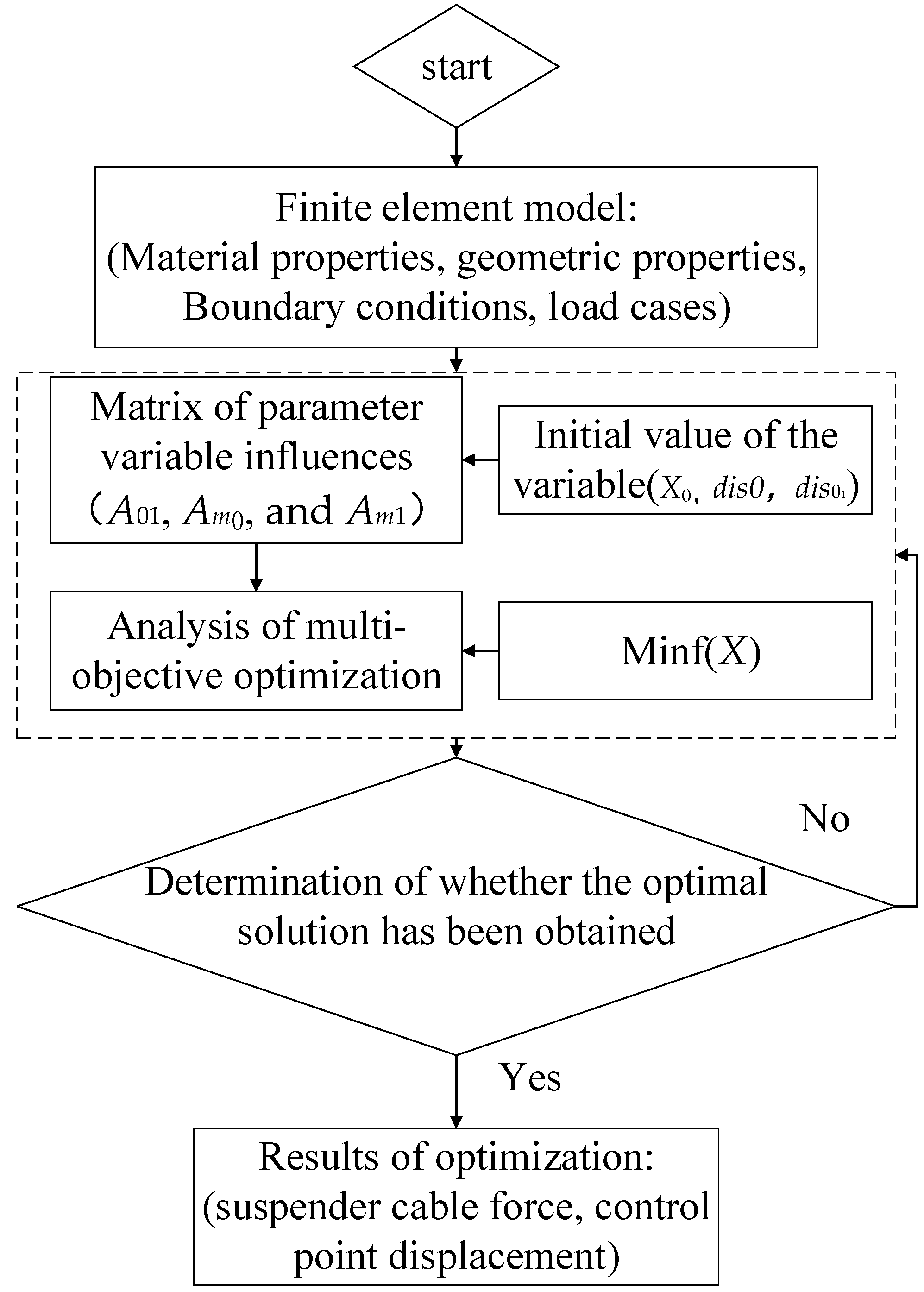
  • Step 1: Firstly, a finite element model is established, of which the material properties, geometric properties, boundary conditions, and external loading information should be consistent with the corresponding data in the design drawing.
  • Step 2: The initial tension forces (X0) for a group of suspenders are then determined, and this group of initial tensions (X0) is substituted into the finite element model in Step 1 for the process of forward analysis and calculation. After obtaining the initial value vectors (dis0 and dis01), the corresponding influence matrices (A01, Am0, and Am1) can be obtained by adding ΔX0.
  • Step 3: An optimization system is established, which should have objective equations, constraints, and parameter variables at the same time. The optimization system includes the following:
The objective equation is provided by:
min f ( X ) = a | A 01 X + A m 01 m + d i s 01 d e s t | + b i = 1 ~ n j = i + 1 ~ n ( δ i j X j ) 2 ,
The constraint condition is then defined by:
{ u = A 0 X + A m 0 m + d i s 0 d e s t | u | d e l t a ε = 1 n i = 1 n ( u i + 1 u i ) 2 < d e l t a ,
The parameter variables are as follows:
d i s 0 = ( s 1 0 , s 1 0 , s 1 0 , , s n 0 ) T ,
d i s 01 = ( s 1 01 , s 2 01 , s 3 01 , , s n 01 ) T ,
X = ( x 1 , x 2 , x 3 , , x n ) T ,
m = ( m 1 , m 2 , m 3 , , m n ) T ,
A 0 = [ δ 11 δ 12 δ 1 n δ 21 δ 22 δ 2 n δ n 1 δ n 2 δ n n ]
A 01 = [ δ ˜ 11 0 0 δ ˜ 21 0 0 δ ˜ n 1 δ ˜ n 2 δ ˜ n n ]
A m 0 = [ Δ 11 m Δ 12 m Δ 1 n m Δ 21 m Δ 22 m Δ 2 n m Δ n 1 m Δ n 2 m Δ n n m ] ,
A m 1 = [ Δ ˜ 11 m 0 0 Δ ˜ 21 m 0 0 Δ ˜ n 1 m Δ ˜ n 2 m Δ ˜ n n m ] ,
where:
u: is the displacement value of the control point for the beam and arch obtained after optimization;
dis0: is the displacement vector of the control points on the bridge deck in the completed state under the action of the initial tension value X0 for the suspenders;
dis01: is the displacement vector of the control points in the current tensioning segment under the action of the initial tension value X0 for the suspenders;
X: is the optimized cable force increment vector;
M: is the real-time corrected weight vector of the grid beam, that is, the difference between the actual weight and the design weight for each segment of the grid beam;
m 1 : is the real-time corrected weight vector of the first grid beam, and so on;
dest: is the target displacement vector of the control points on the bridge deck in the bridge completion stage;
A0: is the influence matrix for the suspender unit force on the displacement of the control points for the grid beam in the completed sections of the bridge;
A01: is the influence matrix for the suspender unit force on the displacement of the control points for the grid beam in the tension sections;
Am0, Am01: is the influence matrix for the weight correction value on the displacement in the completed section of the bridge;
delta: is the allowable value for the optimization convergence, that is, the difference vector between the optimization value and the target value;
δij, δ ˜ i j : refer to the influence value for the tension unit force of the j-th suspender on the displacement of the control points for the grid beam in the i-th section. a and b are the weighting coefficients, satisfying the relationship a2 + b2 = 1, and the corresponding values can be adjusted according to the obtained influence matrix for bridges with different spans.
  • Step 4: The target displacement vector of the control point (dest) is set, generally dest = 0, which can be applied according to different bridge spans.
  • Step 5: The determined parameters are substituted into the optimization equation to calculate the displacement and cable force of each control point for the current tensioning section and the final bridge completion stage.
The optimization process is shown in Figure 2.

3. Engineering Example Description

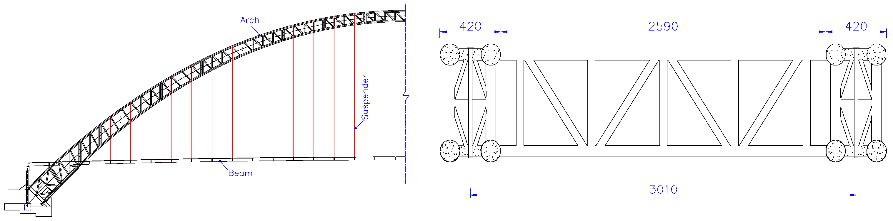
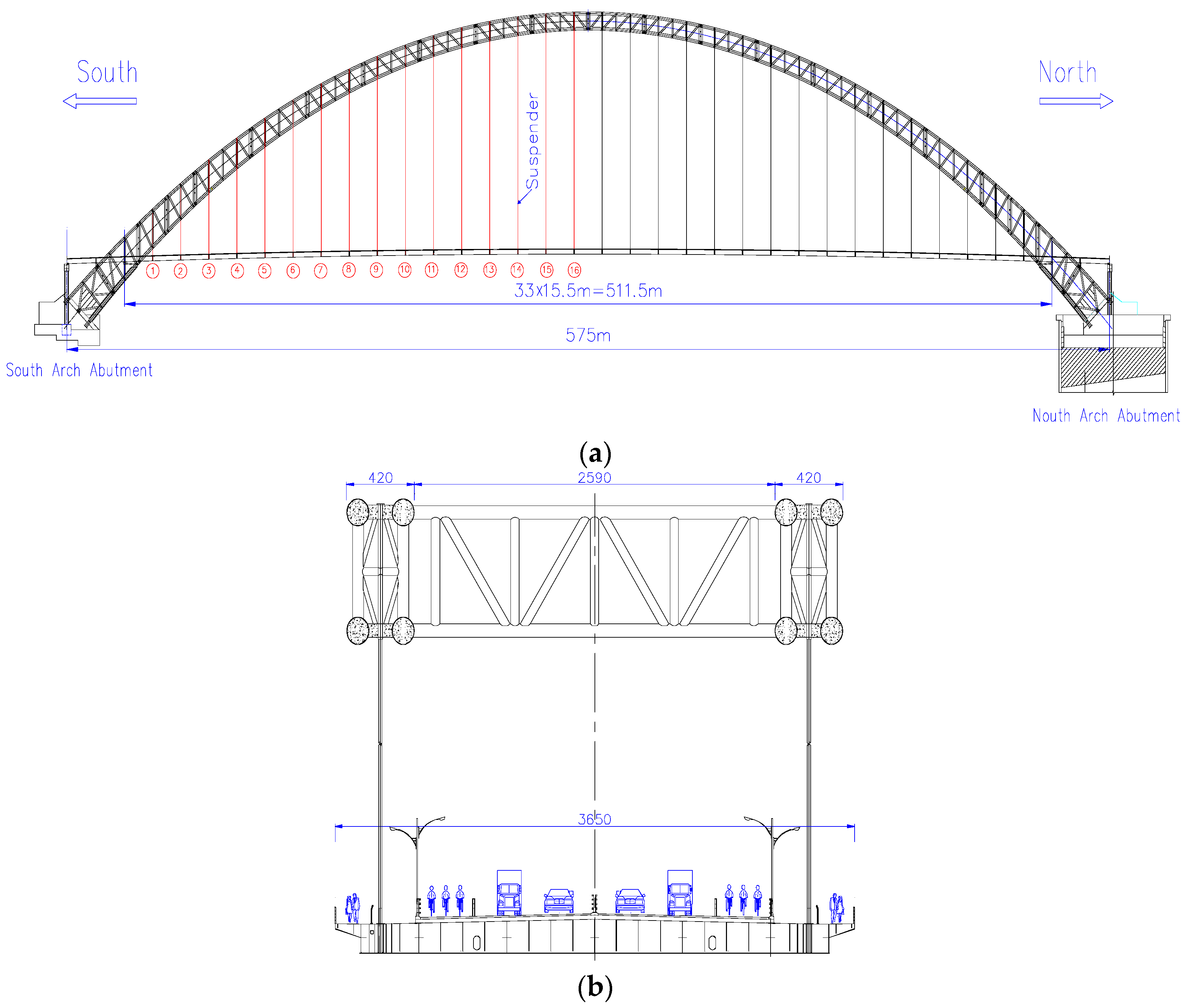
3.1. Third Pingnan Bridge

In this study, the Third Pingnan Bridge, under construction with a structural form spanning 575 m, half of which is through a concrete-filled steel tubular arch bridge, is taken as the research object to explore the application of the proposed suspender cable force optimization method to this engineering project. The calculated rise–span ratio for the Third Pingnan Bridge is 1/4, and the arch axis coefficient is 1.50. The radial height of the arch crown section is 8.5 m and the radial height of the arch foot section is 17.0 m. The rib width is 4.2 m, and each rib has two upper and two lower ribs of Φ 1400 mm concrete-filled steel tube chord, in which C70 concrete is used in the tube. The main beam is a steel–concrete composite grid structure, with suspender spacing of 15.5 m. In the bridge deck system, the main bridge deck pavement adopts the high elastic and high viscosity SMA13 asphalt concrete with a thickness of 5 cm, the thickness of the concrete pavement on the beam is 24 cm, and the thickness between the beams is 15 cm. The cable suspender has 37 Φ 15.2 mm suspender cables made with 1960 MPa grade steel, which are covered with a polyethene (PE) sheath and epoxy-sprayed steel strands with PE wrapped and extruded. There are 16 pairs of suspenders on the north and south riverbanks, and a total of 64 suspenders for the whole bridge. The layout of the bridge deck is shown in Figure 3. Table 1 lists the properties of the materials.
The assembly sequence for grid beams is as follows: (1) the grid beam section between 1# suspender and 2# suspender is firstly assembled; (2) the grid beams among the rib beam, column beam, and beam end section are then installed; and (3) after the first system conversion, the tension of 3# suspender and the corresponding grid beam installation are carried out. In this way, the grid beams are installed symmetrically from the north and south riverbanks to the middle of the span, and the suspenders are tensioned correspondingly until the closure. Finally, the bridge deck, sidewalk slab, and the second-phase pavement are constructed.

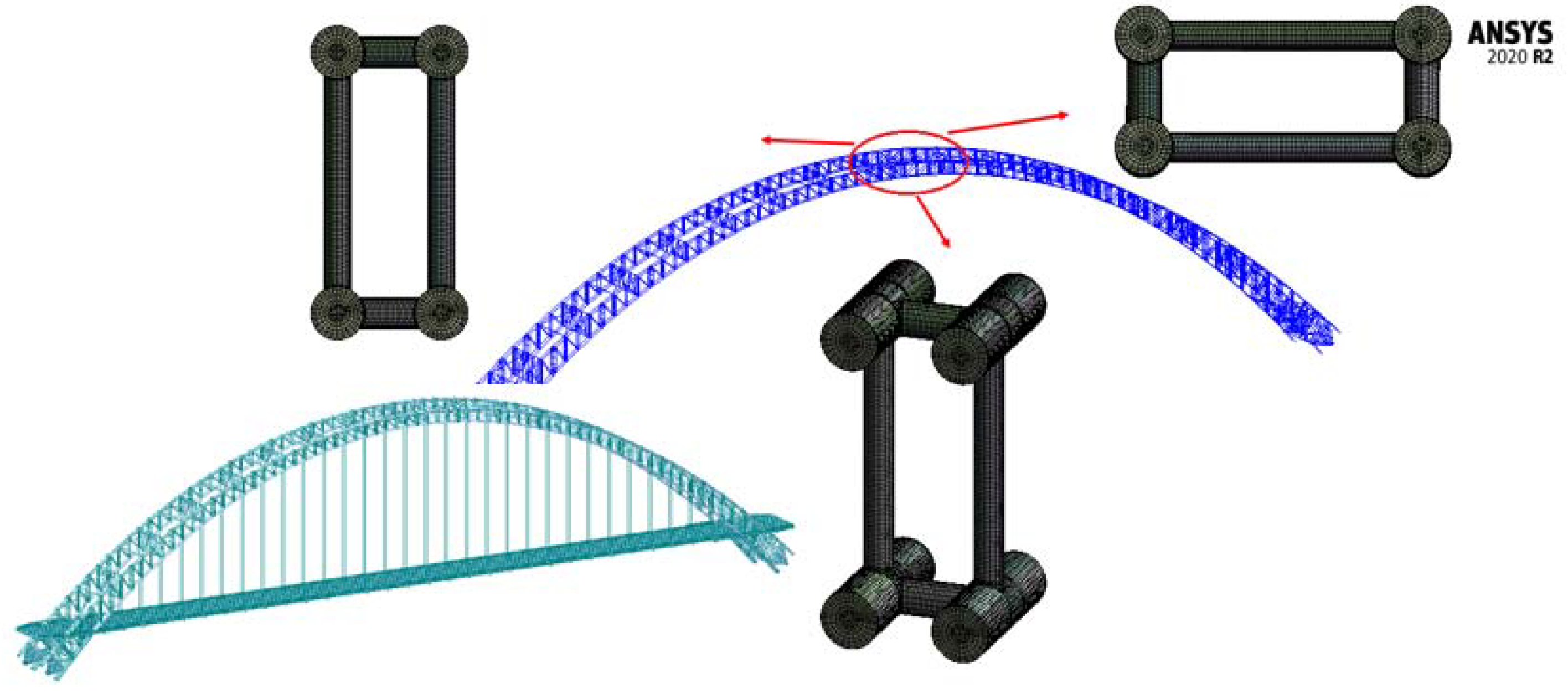
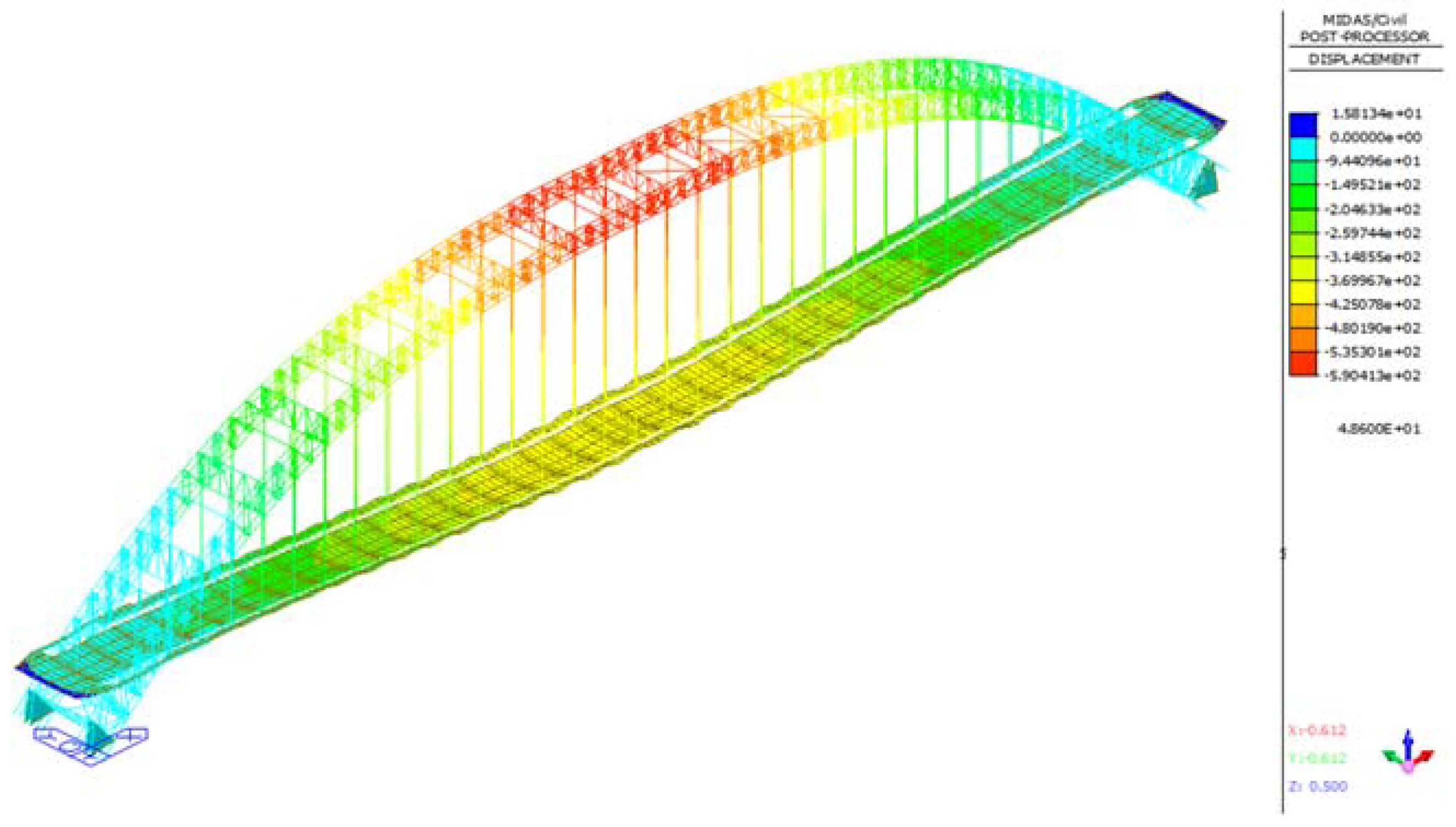
3.2. Modeling Simulation of the Third Pingnan Bridge

In this study, we employed Midas Civil for the modeling to accurately simulate the construction process for the Third Pingnan Bridge. The simulation encompassed various stages, including arch rib hoisting, pouring of the concrete-filled steel tubular sections, grid beam hoisting for the bridge deck, bridge deck construction, and second-phase pavement construction, whilst accounting for the 10-year shrinkage and creep effects [39]. The arch foot was initially treated as a hinge joint until the installation of the No. 6 arch rib cross brace and sealant, after which it was converted into a consolidated form. During the hoisting of the bridge deck grid beam, the beam ends were assumed to be hinged. We represented the arch rib and bridge deck beam using the beam elements, while the suspender and carriageway slab were represented using the truss elements and slab elements, respectively. To minimize the bending moments at the grid beam and suspender joints, we first released the corner constraints at the element joints and then converted them into a consolidated state. Taking into account the structural dead weight, suspender cable force, and second-phase load, we initially added the surface load to the bridge deck beam elements, considering the carriageway slab’s cast-in-situ concrete nature. Subsequently, we activated the bridge deck elements to simulate the stiffness formation. We adopted design values for other parameters in the construction process model, such as the elastic modulus, bulk density, and section size. The total number of nodes and elements in this finite element model of the bridge was 12,349 and 24,355, respectively. The material properties, geometric characteristics, boundary conditions, and external load were the same as the data in the design drawings. The entire bridge was considered to be symmetrical. The inner tube was considered to be made from C70 concrete, with a unit weight of 25 kN/m3 and an elastic modulus of 3.7 × 10⁴ MPa. The outer part of the arch foot section was made from C30 concrete, with a unit weight of 24 kN/m3 and an elastic modulus of 3.0 × 10⁴ MPa. The beam element was used to simulate the arch rib chord and the double elements method was employed to simulate the process of concrete pouring. As for the boundary conditions, the ends of the abutments and towers were fixed. Further, the beam element load was applied to the corresponding position of the concrete that had not yet formed strength. After the concrete was poured, the passivation beam element load was activated by the concrete element at the same time. The established finite model consisted of 8350 nodes and 15,156 elements. Verification was also performed, using ANSYS v2020 R2 software, and the model is illustrated in Figure 4.

4. Optimization Analysis of the Suspender Cable Force

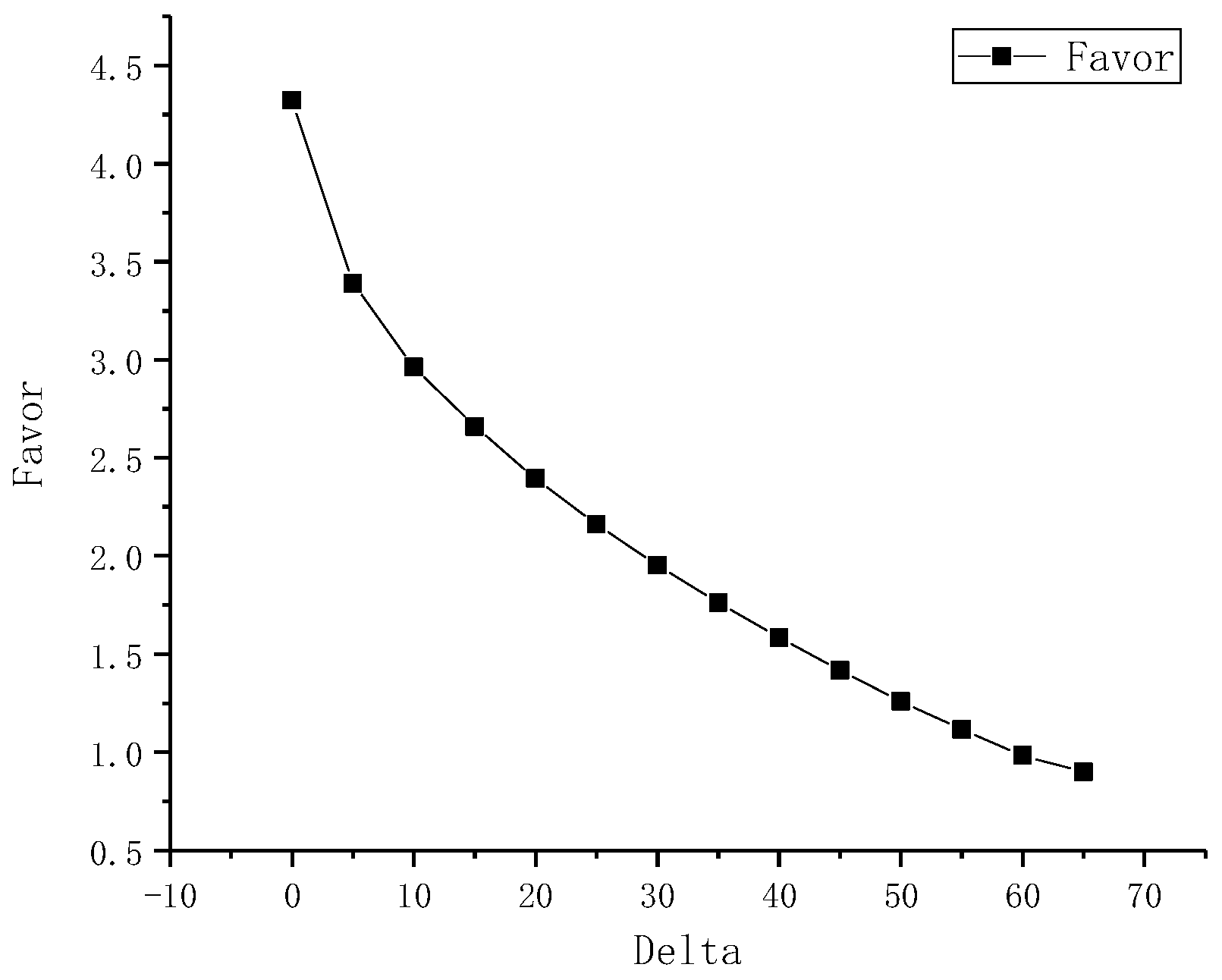
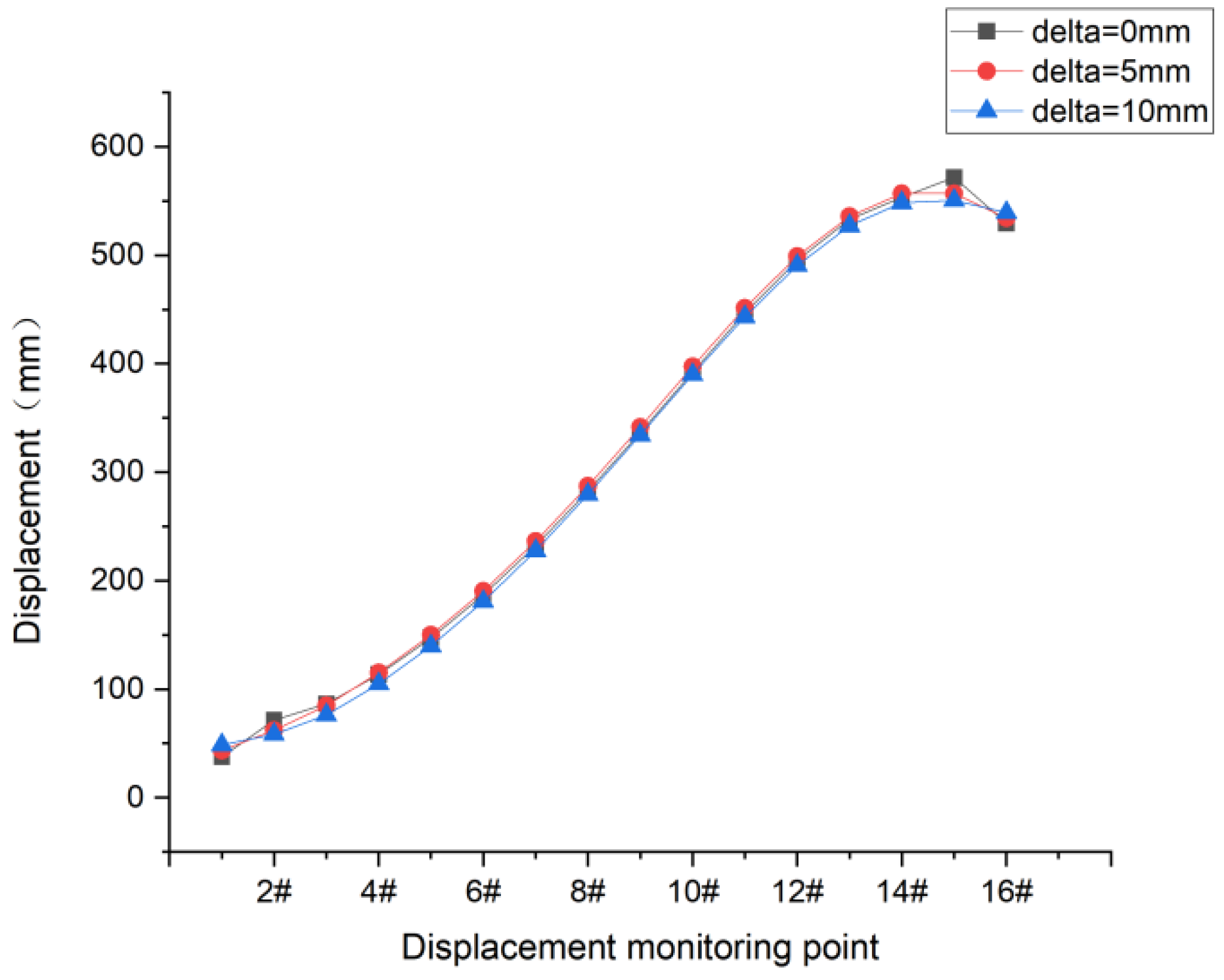
4.1. Analysis of the Allowable Value (Delta) and Optimization Dispersion (Favor) of Optimization Convergence

Based on the above Equation (7), the influence matrix A0 can be obtained through finite element analysis, in which the unit force is 10 kN and the unit is mm. The finite element results are shown in Figure 5.
Based on the finite element results:
A 0 = [ 1 0 0 0 0 0 0 0 0 0 0 0 0 0 0 0 1 1 1 0 0 0 0 0 0 0 0 0 0 0 0 0 1 3 4 1 0 0 0 0 0 0 0 0 0 0 0 0 1 4 7 4 1 0 0 0 0 0 0 0 0 0 0 0 1 5 10 7 4 1 0 0 0 0 0 0 0 0 0 0 1 7 13 11 8 5 1 0 0 0 0 0 0 0 0 0 1 8 16 14 11 8 5 1 0 0 0 0 0 0 0 0 1 9 20 18 15 12 9 5 1 0 0 0 0 0 0 0 1 11 23 21 19 16 12 9 5 1 0 0 0 0 0 0 1 12 26 25 22 19 16 13 9 5 2 0 0 0 0 0 1 13 29 28 26 23 20 17 13 9 5 2 0 0 0 0 1 15 32 31 29 27 24 21 17 14 10 6 2 0 0 0 1 16 36 35 33 31 28 25 21 18 14 10 6 2 0 0 1 17 39 38 37 34 32 29 25 22 18 14 10 6 2 0 1 19 42 42 40 38 36 33 29 26 22 18 14 10 6 2 1 20 45 45 44 42 39 37 33 30 26 22 18 14 10 6 ]
A01 is the lower triangular matrix of A0, which is not listed here. Theoretically, the proposed optimization method for suspender cable force can achieve the process optimization for real-time deviation and correction, according to different actual hoisting weights. In this engineering example, the value m = [1,1,1…1]T, that is, the design weight is recorded at each hoisting stage.
Before the optimization of the suspender cable force, it is found that there is no inflection point in the curves of the allowable value (delta) and optimization dispersion (favor) by analyzing the relationship curve between the delta value and the favor value. However, the slope of the deltafavor curve in the range of 0~10 mm is larger. Therefore, the samples at the delta value of 0 mm, 5 mm, and 10 mm are selected for further comparative analysis to determine the delta value of the optimization. Through a comparison, it is shown that the optimization effects are good when delta = 5 mm and delta = 10 mm. The relationship curve between the delta value and the favor value is shown in Figure 6.
Figure 7, Figure 8 and Figure 9 plot the relationship curves for the optimized initial tension value for suspenders, the suspender cable force, the displacement of the control points for the grid beam in the tension sections, and the delta values. From Figure 5, Figure 6 and Figure 7, it can be seen that with the decrease in the allowable value (delta) of optimization convergence, the initial tension of 3# suspender, 15# suspender, and 16# suspender deviate greatly from the average value, and the cable force of 2# suspender, 14# suspender, and 16# suspender, after the completion of the bridge, also deviate greatly from the average value. When the delta = 0 mm, the initial tension value of 3# suspender is 418 kN, which is 60 kN less than the initial tension value when the delta = 5 mm. The main reason lies in that the target displacement of the bridge deck beam after the completion of the bridge is limited by constraints, which determine the displacement of the grid beams in the current hoisting section within a certain range. When the installed beam section is in place, the displacement difference between the i-th and j-th nodes will lead to the inclination of the beam body. At the same time, the next beam section is tangentially assembled, that is, the preloading of the front section will affect the positioning elevation of the rear section. The greater the inclination angle of the beam body in the front section, the greater the displacement of the beam body in the rear section. However, this displacement of the beam body is limited by constraints. Thus, the suspender cable force in the rear section will become smaller, and the suspender in the front section will also share more of the beam weight, leading to a larger cable force. This also explains why the cable force of 3# suspender and 16# suspender in the tensioning section will be smaller when the delta = 0 and, in the meantime, the cable force of 2# suspender and 15# suspender is larger. The displacement curves for the grid beams in the current hoisting section corresponding to the different delta values have little differences. Considering that the uniformity difference of the suspender cable force and the delta value should be not too large for 1#~16# suspenders in the sections on hoisting and the completion of the bridge, the convergence condition for this optimization is that the delta = 5 mm.

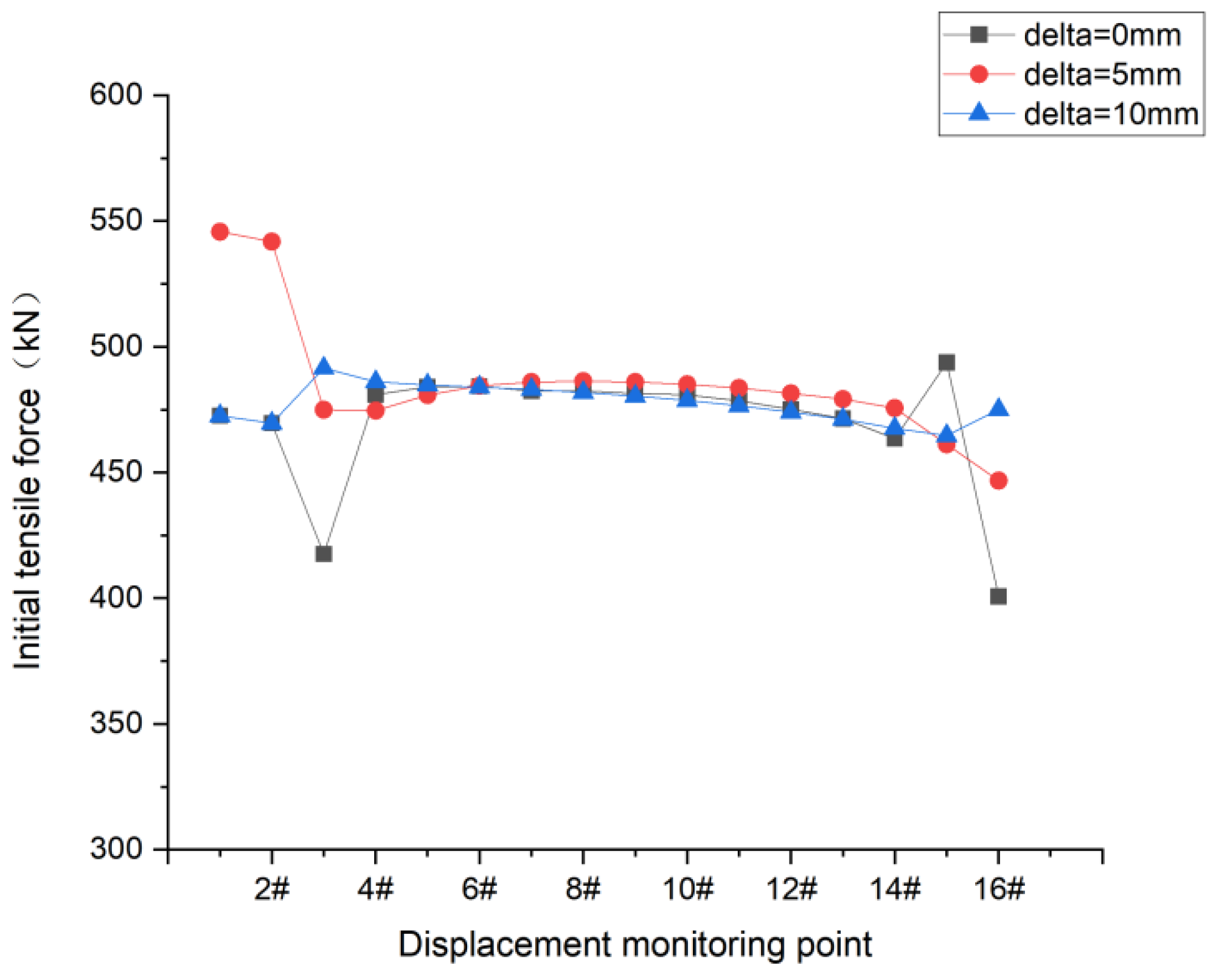
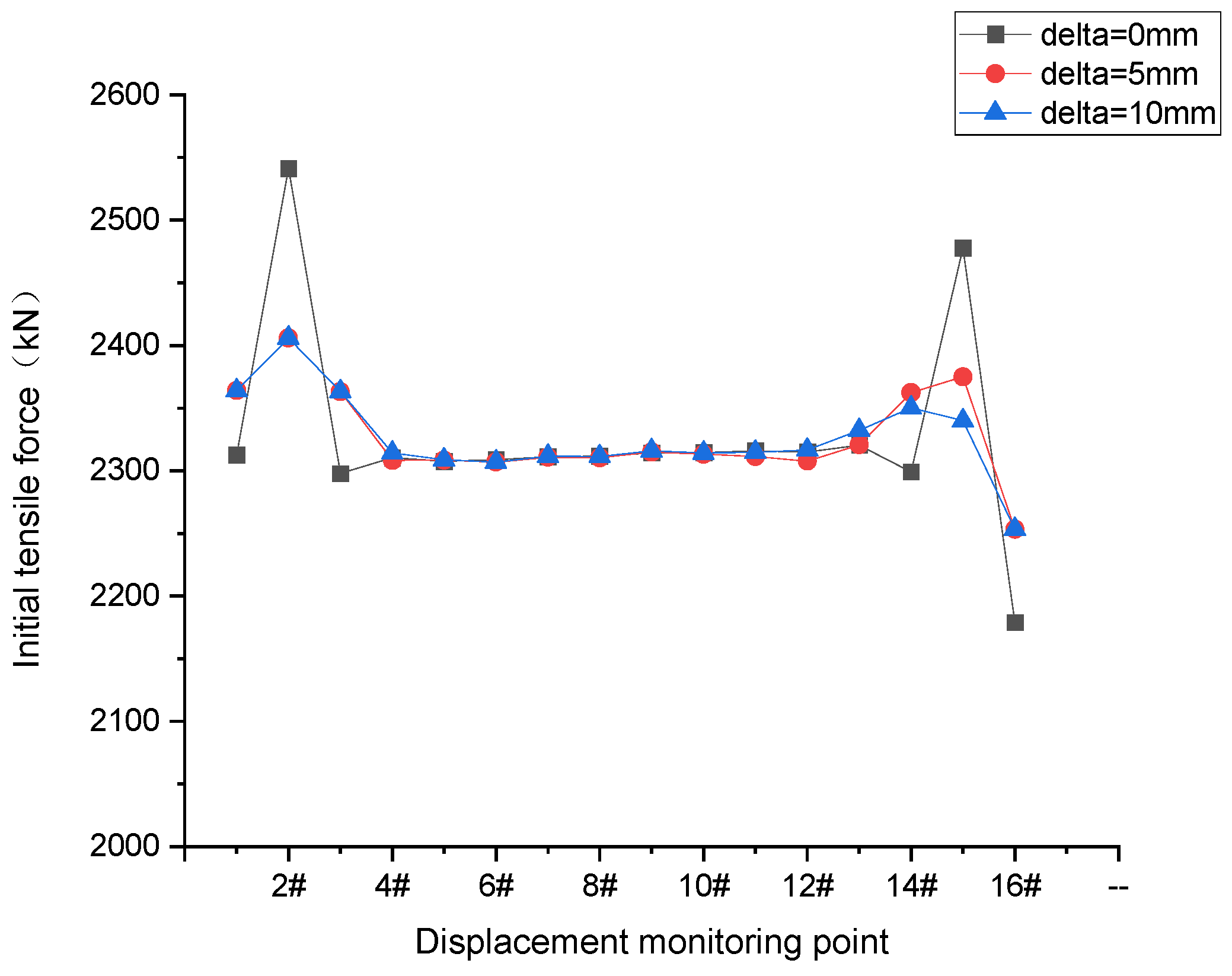
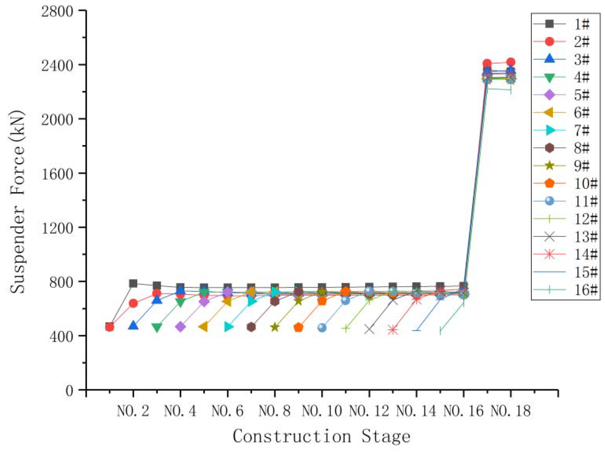
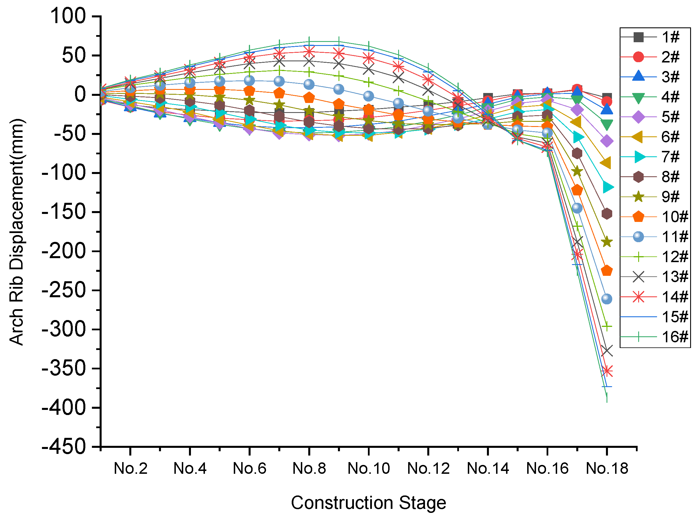
4.2. Optimization Effects of the Suspender Cable Force

This paper considers the minimization of incremental cable forces in the arch bridge during the main girder installation process and the minimization of beam displacement variations as objective functions. Additionally, post-bridge beam and arch displacements are constrained to minimize the difference from the design values. This method is applicable to arch bridges with different construction sequences and spans, and provides a basis for linear control and cable force control during the lifting process for lattice beams. Based on the theory for a new optimization method for suspender cable force in the second section, a set of suspender cable forces can be obtained through optimization, and the displacement of the control points for the grid beam can be also obtained through forward analysis. The calculation results for the suspender cable force are shown in Table 2 and Figure 10, the displacement results for the grid beam at the hoisting points are shown in Table 3 and Figure 11, and the arch rib displacement results at the hoisting points are shown in Table 4 and Figure 12.
From Table 2, Table 3 and Table 4 and Figure 10, Figure 11 and Figure 12, it can be seen that the final optimization target (delta = 5 mm) is feasible. During the period from hoisting to closure, the differences between the maximum and minimum cable forces for 3# suspender ~15# suspender are within the range of (258 ± 2) kN, which occurs during the grid beam hoisting in the rear section. The standard deviations of the displacement values for 1# suspender~10# suspender are (15 ± 2) mm, and those for 11# suspender~16# suspender are (35 ± 9) mm. The optimized suspender cable force changes smoothly during the whole construction process, and the subsequent construction stage has the least impact on the displacement of the completed construction section, which achieves a very good optimization effect.

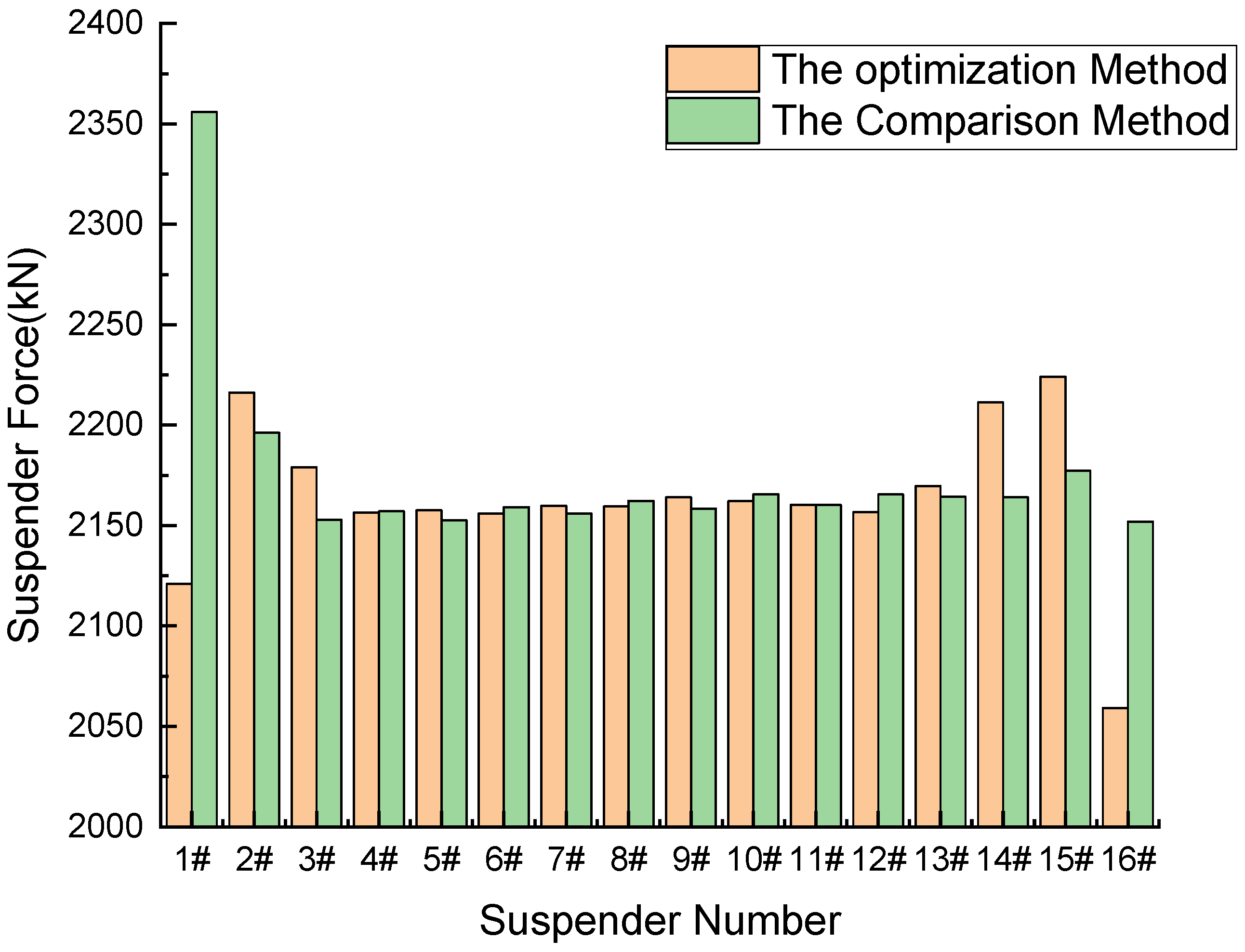
4.3. Verification of the Optimization Method for Suspender Cable Force

The cable force was determined using vibration measurement. The principle of measuring the cable force with the vibration frequency method is that there is a corresponding relationship between the cable tension and cable vibration frequency under certain conditions. When the cable’s length, distribution mass, and flexural stiffness are known, the cable tension can be calculated based on the vibration frequency of the cable strand. To verify the feasibility of the proposed optimization method for determining the suspender cable force, the minimum bending energy method was adopted to calculate the suspender cable force after the completion of the bridge. The results obtained by the proposed method and the minimum bending energy method were compared and analyzed. The minimum bending energy method uses structural bending residual energy as the objective function to optimize the suspender cable force after the completion of the bridge. It is one of the commonly used calculation methods for determining the suspender cable force after bridge completion. However, the minimum bending energy method is only suitable for cable force adjustment under dead load conditions. The comparison results for the suspender cable forces after the completion of the bridge, obtained by the proposed method and the minimum bending energy method, are shown in Figure 13. The comparison results for the bearing reactions are listed in Table 5.
The measured cable forces after upstream and downstream adjustment are shown in Figure 14.
Figure 14 indicates that the construction monitoring for the bridge was started when the deck concrete was paved. After adjusting the cable force based on the practical optimal method, the difference between a single completion cable force and the theoretical value is less than 5%, and such difference in the cable force of the whole bridge is 1.37%. Moreover, alignments of the arch rib and the bridge deck are generally smooth.
According to the above comparison results, it can be seen that the calculation results from the proposed method and the minimum bending energy method are very close, but the suspender cable force optimized by the proposed method is more uniform. The proposed optimization method takes the construction process into account, and can obtain the suspender cable force and the displacement of the grid beam in the current tensioning section, which can be used to guide the construction. This proposed optimization method can ensure that the displacement of the grid beam changes little during the construction process, and that the bridge alignment after the completion of the bridge meets the control requirements. It can be seen from Table 5 that there is a slight deviation in the external force distribution of the bridge deck system calculated by these two methods. The support reaction force calculated by the proposed optimization method is too large, while the suspender cable force is too small, and the resultant force remains unchanged. This is mainly because the construction sequence, and the shrinkage and creep effects are considered in this method, and some loads are transferred from the suspender to the column, and the cross beam between the ribs during the construction process are considered in the proposed optimization method. The above calculations are based on the design weight. When the weight of the grid beam is 1.05 times that of the design value, the difference in the pre-lift value of the grid beam in the hoisting section calculated by the proposed optimization method will be within 5 mm, and the initial tension force for the suspenders increases by 5%. And the increase in the grid beam weight has little impact on its displacement, and the suspender cable force will change accordingly. When the actual weight of the grid beam deviates from the theory values, the m values can be corrected in the optimization system to reanalyze the displacement and suspender cable force in the next hoisting section, so as to realize dynamic deviation correction. The optimization of the suspender cable force in the construction of the bridge deck system for a concrete-filled steel tubular arch bridge is feasible, and the optimization effect is good. The results can be optimized at one time without repeated iterative calculations, so that the cable will not be adjusted during the process. At the same time, it ensures the minimum displacement change in the grid beam and cable force during the construction process. According to the measured values, the parameters can also be corrected and reoptimized in time to ensure that the completed bridge state meets the design requirements.

5. Conclusions

Zheng Dulian [1] mentioned that the ratio of the concrete-filled steel tubular arch bridge to the steel arch bridge has good mechanical performance; compared with the cable-supported bridge, the stiffness is larger, it has low temperature sensitivity and good seismic performance; and its advantages are obvious. As a branch of the arch bridge, the rapid increase in the number and span of such bridges in China and, even, the world is a miracle in the bridge industry. In the future, steel-tube arch bridges must develop towards larger spans, more design innovation, and new construction technology. As an important part of bridge structure, suspenders need more and better cable force optimization methods to guide construction. Taking the Pingnan Third Bridge as the engineering background, an efficient, accurate and real-time deviation correction method for suspender cable force optimization is explored. The following conclusions are drawn:
(1)
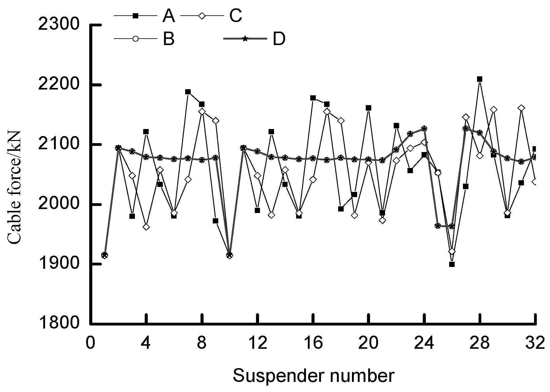
In this paper, a new method for optimizing suspender cable force is proposed, which can minimize the increment of lattice beam displacement and target value differences in the construction process. The subsequent tensioning section has the least impact on the displacement of the constructed section, the standard deviation of the displacement of 1# suspender ~ 10# suspender is 15mm ± 2mm, and the standard deviation of the displacement of 11# suspender~16# suspender is 35mm ± 9mm. The cable force of the completed bridge is uniform, the standard deviation of the suspender cable force is only 43 kN, and the difference between the maximum cable force and the minimum cable force is 203 kN. The alignment of the completed bridge converges to the target value, the displacement is within 5mm, and the calculation result is reliable.
(2)
The bridge deck system construction of a concrete-filled steel tubular arch bridge with different spans and construction sequences is calculated quickly, which has strong practicability and a wide application range.
(3)
The traditional reverse demolition method is simple and practical for implementation but overlooks important factors, such as concrete shrinkage, creep, and structural geometric nonlinearity. For complex structures, the existing optimization methods for suspender cable forces involve extensive matrix operations that demand high computational power and time. Consequently, obtaining a more accurate solution becomes challenging. To address this, a new method for cable force optimization is proposed to improve the stress distribution of suspenders in the completed state and minimize the need for frequent cable force adjustments and grid beam elevation changes during construction. This method offers several advantages over other approaches. Unlike the forward iteration method, it avoids the need for repetitive calculations once the cable force after the completion of the bridge is known. Additionally, compared to the minimum bending energy method, it considers the construction process, resulting in calculation conditions that closely reflect the actual situation. As a result, it can more accurately simulate the load distribution of the bridge deck system.
(4)
In the actual bridge hoisting construction, through the real-time correction of the design parameters and system reoptimization, process deviation correction can be realized, so as to ensure that the completed bridge state meets the requirements.
The internal force matrix method is a widely utilized structural optimization technique. However, when applied to complex structures, the problem-solving process involves extensive matrix operations that require substantial computing power and time. In this study, we have taken into account the characteristics of real-world engineering and focused on specific key points to reduce the order of the influence matrix. Consequently, the computational costs are reduced, facilitating the development of a multi-objective tension optimization program.

Author Contributions

Conceptualization, M.Y. and X.Y.; methodology, M.Y.; formal analysis, N.D., T.H., L.W. and H.W.; investigation, N.D. and T.H.; data curation, X.Y.; writing—original draft preparation, M.Y.; writing—review and editing, X.Y.; funding acquisition, M.Y. All authors have read and agreed to the published version of the manuscript.

Funding

This study was partly sponsored by following fund programs: (1) the National Natural Science Foundation of China (Code: 51738004); (2) the National Natural Science Foundation of China (Code: 51868006); (3) the National Natural Science Foundation of China (Code: 51878186); (4) the Guangxi Natural Science Foundation co-funded cultivation project (2018GXNSFAA138067); (5) the Nanning City “Yongjiang Project” funded project (2018-01-04).

Data Availability Statement

The testing and analysis data used to support the findings in this study are included within the article.

Conflicts of Interest

The authors declare no conflict of interest.

References

  1. Zheng, J. Innovative Technology for 500-Meter Scale CFST Arch Bridge Construction; Shanghai Science and Technology Press: Shanghai, China, 2020. [Google Scholar]
  2. Zheng, J. Quality and Risk: Concrete Filled Steel Tubular Arch Bridge. China Highw. 2018, 22, 40. [Google Scholar]
  3. Chen, B. CFST Arch Bridge; People’s Communications Press: Beijing, China, 2007. [Google Scholar]
  4. Zheng, J. Development and prospect of long-span arch bridge. China Highw. 2017, 13, 40–42. [Google Scholar]
  5. Zheng, J.; Wang, J.; Mou, T.; Fenh, Z.; Han, Y.; Qin, D. Feasibility Research on Design and Construction of 700 m CFST Arch Bridge. China Eng. Sci. 2014, 16, 5. [Google Scholar]
  6. Chen, B.; Zheng, J.; Zhou, J. pplication status and Prospect of CFST arch bridge in China. J. Civ. Eng. 2017, 50, 12. [Google Scholar]
  7. Zheng, J.; Wang, J. Concrete-Filled Steel Tube Arch Bridge in China. Engineering 2018, 4, 13. [Google Scholar] [CrossRef]
  8. Yan, D. Iterative method for determining the reasonable construction state of cable-stayed bridges. China J. Highw. Transp. 1999, 12, 6. [Google Scholar]
  9. Li, Q.; Zhao, Z.; Jie, L. Application of iterative method in construction control of suspender of tie-down tied arch bridge. China Foreign Highw. 2015, 35, 4. [Google Scholar]
  10. Yang, J.; Shen, C.; Sheng, J. Summarizing the Methods of Determination of Rational Completion Status of Cable-Stayed Bridges. Eng. Sci. 2006, 4, 9. [Google Scholar]
  11. Xin, K. Nonlinear backward analysis of large span cable-stayed bridge construction. Eng. Mech. 2004, 5, 31–35. [Google Scholar]
  12. Xu, Y.; Zhan, B.; Li, Y. An Optimum Calculation Method of Cable Force of CFST Arch Bridge in Inclined Cable Hoisting Construction. Highw. Transp. Sci. Technol. 2016, 33, 7. [Google Scholar]
  13. Sung, Y.-C.; Chang, D.-W.; Teo, E.-H. Optimum post-tensioning cable forces of Mau-Lo Hsi cable-stayed bridge. Eng. Struct. 2006, 28, 1407–1417. [Google Scholar] [CrossRef]
  14. Liu, Z. Determination of the optimal hanger for tied-arch bridges based on energy methods. Eng. Mech. 2009, 26, 6. [Google Scholar]
  15. Zhao, W.; Zhen, J.; Lu, S. Optimization Analysis of suspender tension in super long-span tied steel arch bridge at completion state. J. China Foreign Highw. 2016, 36, 6. [Google Scholar]
  16. Zhang, J.; Zheng, Y.; Xiao, R. Calculation method for optimizing the installation process of concrete-filled steel tube arch bridge. J. China Highw. 2005, 18, 40–44. [Google Scholar]
  17. Xiao, R.; Xiang, H. Influence matrix method of tension optimization for cable-stayed bridges. J. Tongji Univ. (Nat. Sci. Ed.) 1998, 26, 6. [Google Scholar]
  18. Che, X.; Du, B.; Zhang, X. Comparative Analysis of Methods for Determining the Suspension Cable Force of the Reinforced Concrete Tied Arch Bridge. Constr. Technol. 2018, 47, 4. [Google Scholar]
  19. Fu, J.; Huang, T. Applicability analysis of Optimum Methods for hanger forces of rigid tied-arch bridges at completion stage. J. Railw. Sci. Eng. 2014, 11, 8. [Google Scholar]
  20. Yang, X.; Zhou, S. Method to determine construction cable tension force of cable-stayed bridge. J. Chongqing Jiaotong Univ. (Nat. Sci.) 2008, 27, 5. [Google Scholar]
  21. Nakayama, H.; Kaneshige, K.; Takemoto, S.; Watada, Y. An application of a multi-objective programming technique to construction accuracy control of cable-stayed bridges. Eur. J. Oper. Res. 1995, 87, 731–738. [Google Scholar] [CrossRef]
  22. Zhang, Z.; Wang, Y. Optimization of stayed-buckle cable forces during adjustment of alignment on long span arch bridges. Eng. Mech. 2004, 21, 6. [Google Scholar]
  23. Han, Y.; Qin, D.; Zheng, J. Optimal calculation method for CFST arch bridge during cable-stayed buckle construction. Highway 2018, 63, 5. [Google Scholar]
  24. Du, H.; Qin, D.; Luo, X. Construction control of super-long-span arch bridges. Highway 2019, 6, 103–107. [Google Scholar]
  25. Jie, D.; Feng, J.; Qin, F.; Jin, D.; Cheng, Y. Review on Cable Force Optimization Method for Cable-stayed Bridge in Completed Bridge State. China J. Highw. Transp. 2019, 32, 5. [Google Scholar]
  26. Zhan, Y.; Hou, Z.; Shao, J. Cable Force Optimization of Irregular Cable-Stayed Bridge Based on Response Surface Method and ParticleS warm Optimization Algorithm. Bridge Constr. 2022, 52, 3. [Google Scholar]
  27. Kasuga, A.; Arai, H.; Breen, J.E.; Furukawa, K. Optimum cable-force adjustments in concrete cable-stayed bridges. J. Struct. Eng. 1995, 121, 685–694. [Google Scholar] [CrossRef]
  28. Martins, A.; Simões, L.; Negrão, J. Optimization of cable forces on concrete cable-stayed bridges including geometrical nonlinearities. Comput. Struct. 2015, 155, 18–27. [Google Scholar] [CrossRef]
  29. Baldomir, A.; Hernandez, S.; Nieto, F.; Jurado, J.A. Cable optimization of a long span cable stayed bridge in La Coruña (Spain). Adv. Eng. Softw. 2010, 41, 8. [Google Scholar] [CrossRef]
  30. Hassan, M. Optimization of stay cables in cable-stayed bridges using finite element, genetic algorithm, and B-spline combined technique. Eng. Struct. 2013, 49, 643–654. [Google Scholar] [CrossRef]
  31. Negrão, J.H.O.; Simões, L.M.C. Optimization of cable-stayed bridges with three-dimensional modelling. Comput. Struct. 1997, 28, 18. [Google Scholar] [CrossRef]
  32. Guo, J.; Yuan, W.; Dang, X.; Alam, M.S. Cable force optimization of a curved cable-stayed bridge with combined simulated annealing method and cubic B-Spline interpolation curves. Eng. Struct. 2019, 201, 109813. [Google Scholar] [CrossRef]
  33. Janjic, D.; Pircher, M.; Pircher, H. Optimization of Cable Tensioning in Cable-Stayed Bridges. J. Bridg. Eng. ASCE 2003, 8, 131–137. [Google Scholar] [CrossRef]
  34. Latif, M.; Saka, M. Optimum design of tied-arch bridges under code requirements using enhanced artificial bee colony algorithm. Adv. Eng. Softw. 2019, 135, 102685. [Google Scholar] [CrossRef]
  35. Martins, A.M.; Simões, L.M.; Negrão, J.H. Optimization of cable-stayed bridges: A literature survey. Adv. Eng. Softw. 2020, 149, 102829. [Google Scholar] [CrossRef]
  36. Wang, Z.; Zhang, N.; Du, X.; Wang, S.; Sun, Q. Multiobjective Optimization of Cable Forces and Counterweights for Universal Cable-Stayed Bridges. J. Adv. Transp. 2021, 2021, 6615746. [Google Scholar] [CrossRef]
  37. Guo, J.; Guan, Z. Optimization of the cable forces of completed cable-stayed bridges with differential evolution method. Structures 2023, 47, 1416–1427. [Google Scholar] [CrossRef]
  38. Wang, Z.; Zhang, N.; Cheng, Q. Multi-objective optimization-based reasonable finished state in long-span cable-stayed bridge considering counterweights. Structures 2023, 51, 1497–1506. [Google Scholar] [CrossRef]
  39. Zucca, M.; Crespi, P.; Stochino, F.; Puppio, M.L.; Coni, M. Maintenance interventions period of existing RC motorway viaducts located in moderate/high seismicity zones. Structures 2023, 47, 976–990. [Google Scholar] [CrossRef]
Figure 1. A CFST arch bridge structure diagram.
Buildings 13 02214 g001
Figure 2. The optimization process for the suspender cable force in this study.
Buildings 13 02214 g002
Figure 3. General layout of the CFST arch bridge, the Third Pingnan Bridge (unit: cm): (a) description of what is contained in the first panel; (b) description of what is contained in the second panel.
Buildings 13 02214 g003
Figure 4. The finite element model diagram.
Buildings 13 02214 g004
Figure 5. Finite element results diagram.
Buildings 13 02214 g005
Figure 6. The relationship between the allowable value (delta) and optimization dispersion (favor).
Buildings 13 02214 g006
Figure 7. The relationship between the delta value and initial tension value for the suspenders.
Buildings 13 02214 g007
Figure 8. The relationship between the delta value and the suspender cable force after the completion of the bridge.
Buildings 13 02214 g008
Figure 9. The relationship between the delta value and the displacement of the control points for the grid beam in the tension sections.
Buildings 13 02214 g009
Figure 10. The variation curves for the suspender cable force versus the construction stage.
Buildings 13 02214 g010
Figure 11. The variation curves for the displacement results for the grid beam at the hoisting points versus the construction stage.
Buildings 13 02214 g011
Figure 12. The variation curves for the arch rib displacement results at the hoisting points versus the construction stage.
Buildings 13 02214 g012
Figure 13. The comparison of the suspender cable forces after the completion of the bridge using the proposed method and the minimum bending energy method.
Buildings 13 02214 g013
Figure 14. Completion cable force after adjustment. A: cable force measured before upstream adjustment; B: upstream target value; C: measured cable force after downstream adjustment; D: downstream target value.
Buildings 13 02214 g014
Table 1. The properties of the materials used in the Third Pingnan Bridge.
ComponentsElastic Modulus/MPaBulk Density/kN·m−3Section Size/mm
Main chord tube2.06 × 10578Φ 1400 × 26
Suspender1.95 × 1057837 Φ 15.2
Main beam2.06 × 105782200
C403.25 × 10425240/150
C703.70 × 10425Φ 1400
Table 2. Suspender cable force values in different construction sections.
Construction StageSuspender Cable Force Values in Different Construction Sections/kN
1#2#3#4#5#6#7#8#9#10#11#12#13#14#15#16#
1# and 2# tension46846300000000000000
3# tension7846384700000000000000
4# tension769711660466000000000000
5# tension75770773065246700000000000
6# tension7546977277226524670000000000
7# tension755694717721722653466000000000
8# tension75569571371172272365446400000000
9# tension7556977137067117237236544620000000
10# tension756698714706707713724724655460000000
11# tension75769871470770670871372572565745700000
12# tension7586997157077077077087147257266594530000
13# tension759699715707707708707708713726728661449000
14# tension76170071570770870870870770871472673066344400
15# tension7627007157077087087097087077087147277316674380
16# tension764701715707708708709709708707708714727734666435
Closure stage765701715707708708709709708708706707717743750643
After pavement2358240823472299229322932295229422952294229222932304232923362222
Table 3. Displacement values for the grid beam at the hoisting points in different construction sections.
Construction StageDisplacement Values for the Grid Beam in Different Construction Sections/mm
1#2#3#4#5#6#7#8#9#10#11#12#13#14#15#16#
1# and 2# tension4362--------------
3# tension294785-------------
4# tension263969115------------
5# tension23345997150-----------
6# tension21315486130190----------
7# tension20295180118169236---------
8# tension20284977113157214287--------
9# tension20284876111153202264342-------
10# tension21294977111151198252317397------
11# tension23325279112152198249305371451-----
12# tension26365784117156200249301357421499----
13# tension30416391123161204251301352405464536---
14# tension34477099131169210254301349396443494557--
15# tension385479108141178217259303347389429466506557-
16# tension436188118151187226265305344382416446472498534
Closure stage456391122155191229267306343379411439460475495
After pavement151120324354678094107120131140146150164
Shrinkage and creep5−5−21223444331−3−44
Table 4. Arch rib displacement results at the hoisting points in different construction sections.
Construction StageArch Rib Displacement in Different Construction Sections/mm
1#2#3#4#5#6#7#8#9#10#11#12#13#14#15#16#
1# and 2# tension−6−7−6−5−4−3−1013467788
3# tension−13−16−16−14−12−9−6−22591214161819
4# tension−17−22−24−23−19−15−10−417121721242628
5# tension−19−26−30−31−28−22−15−807152228323638
6# tension−21−30−36−38−36−31−23−13−37172634414547
7# tension−23−32−40−43−43−39−31−20−75182940485457
8# tension−23−34−42−47−49−46−39−28−132173143536064
9# tension−23−33−42−49−51−50−45−35−21−4132943556368
10# tension−21−32−41−48−52−52−48−40−28−1272440536368
11# tension−19−29−38−45−50−52−49−43−33−19−21633475762
12# tension−16−25−34−41−46−48−48−44−37−26−11522364651
13# tension−13−20−27−34−39−43−44−43−38−31−21−86192934
14# tension−9−14−20−26−31−35−38−39−38−35−30−22−13−459
15# tension−4−8−12−16−21−26−31−34−37−38−38−36−33−29−25−22
16# tension10−3−6−11−16−22−28−34−40−45−50−54−56−58−58
Closure stage221−3−7−13−19−26−34−41−49−56−62−67−71−73
After pavement672−6−19−35−54−75−98−122−145−168−188−204−217−225
Table 5. The comparison of the bearing reaction using the proposed method and the minimum bending energy method.
MethodsBridge Components/kN
Beam EndColumn and Cross Beam Between RibsSuspenderResultant Force
The proposed method465920,180147,845172,684
Minimum bending energy method499318,852148,838172,684
Difference−3351328−9930
Disclaimer/Publisher’s Note: The statements, opinions and data contained in all publications are solely those of the individual author(s) and contributor(s) and not of MDPI and/or the editor(s). MDPI and/or the editor(s) disclaim responsibility for any injury to people or property resulting from any ideas, methods, instructions or products referred to in the content.

