Article

Nonlinear Stress-Free-State Forward Analysis Method of Long-Span Cable-Stayed Bridges Constructed in Stages

1
School of Transportation and Geomatics Engineering, Yangling Vocational and Technical College, Yangling 712100, China
2
Changsha Planning and Design Institute Co., Ltd., Changsha 410007, China
3
School of Highway, Chang’an University, Xi’an 710064, China
*
Author to whom correspondence should be addressed.
Buildings 2023, 13(7), 1735; https://doi.org/10.3390/buildings13071735
Submission received: 6 June 2023 / Revised: 28 June 2023 / Accepted: 4 July 2023 / Published: 8 July 2023

Abstract

:
Structural analysis and construction control of staged-construction processes are major subjects in the context of modern long-span bridges. Although the forward and backward analysis methods are able to simulate situations, their main disadvantage is that they usually apply the stage superposition principle. In the actual construction process, due to changes made to the plan, the construction process needs to be adjusted at any time, and it is difficult to implement the construction process in complete accordance with the established plan. As a result, the existing simulation method based on the incremental structural analysis of each construction stage has poor adaptability to such adjustments. In this study, considering the strong geometric nonlinear behavior of the long-span cable-stayed bridge construction process, the geometrically nonlinear mechanical equations of the staged-construction bar system structure were derived. The minimum potential energy theorem was used by introducing the concept of the stress-free-state variable of the structural elements. The equation reflects the influence of the change in the stress-free-state variables of structural elements on the completion state of the structure. From the analysis of the geometrical condition that the equilibrium equation holds, the stress-free installation condition of the closing section of the planar beam element structure was obtained. A new simulation method for long-span cable-stayed bridge construction has been proposed, which is called the stress-free-state forward analysis. This method can directly obtain the intermediate process state of cable-stayed bridge construction without performing stage-by-stage demolition calculations, and causing the internal force and deformation of the completion state to reach the design target state. This method can realize the simulation of multi-process parallel operation in construction, and solves the problem of automatic filtering of temporary loads. To illustrate the application of the method, a long-span cable-stayed bridge was analyzed.

1. Introduction

A cable-stayed bridge is a complex, statically indeterminate structure due to the presence of cable forces and their gradual tensioning process [1]. Staged construction, as well as the one-step scaffold-supported bridge construction, are two methods commonly used in the construction of cable-stayed bridges [2,3,4]. In the second half of the nineteenth century, the balanced cantilever construction method without scaffolding was first proposed. In the 1930s, the cantilever segmental construction method was used to construct concrete arch bridges. After World War II, cantilever cast-in-place and precast segmental assemblies were developed with the development of prestressed concrete technology [5,6,7]. Staged construction represented by the balanced cantilever construction method has been widely used in the construction of beam bridges, cable-stayed bridges, and arch bridges.
During the staged construction of a cable-stayed bridge, the tensioning operation of the cables plays an important role in the construction of the structure [8,9,10]. Since these are time-consuming and labor-intensive operations, the main aim of the cable-stayed bridge installation calculation and construction control should be to minimize the number of cable tensions and achieve the design target state of cable force after construction, so that there is no need for any final adjustment of cable force [11,12,13].
Furthermore, as the structure gradually takes shape during staged construction, the stiffness of the structural system during construction may differ from that in the completed state [14,15]. Therefore, to maintain structural safety, it is important to simulate the beam section installation and the stay cable tensioning process to ensure that the limit state is not exceeded during construction [16,17].
Due to the time-dependent nature of the structural system state and the dead load application of staged bridge construction, traditional structural analysis theories that do not consider the effects of the construction process cannot be directly applied [18]. Therefore, scholars have endeavored to take the construction stage of bridges into consideration and proposed several methods based on incremental structural analysis of each construction stage, such as the forward analysis [19,20] and backward analysis [19,21,22,23,24]. The relationship between the process state and the final design target state is established through the staged numerical accumulation of the internal force and deformation of the structure using the above methods.
For a staged-construction structure, the method of structural analysis according to the time sequence of construction is called forward analysis. The purpose of forward analysis is to check whether the stress generated in each construction stage is within the controllable range, so as to check the feasibility of the construction method, and finally, determine the optimal construction method. The balanced cantilever construction method is usually adopted for long-span cable-stayed bridges. The construction process undergoes frequent system transformations and loadings, accompanied by complex, strongly geometrically nonlinear behavior. Accurate state assessment of such processes generally requires nonlinear finite element analysis to perform step-by-step forward and cumulative calculations based on the principle of incremental superposition [11,25]. This calculation implies that the structural equilibrium for any intermediate state of the process must be accumulated from its previous construction loading history, which is easily limited by computational effort and convergence.
Alternatives to these methods were proposed by Lozano-Galant et al. [26]. Their approach presents an innovative direct analysis method that uses independent finite element models for each construction stage. In order to ensure that the design target state is achieved after construction, the stay-cable force is simulated using the concept of stress-free-state length. Therefore, without the need for an overall iterative calculation process, the direct methods can be easily used for optimization problems. This direct simulation approach is proposed only for temporary support erection methods, and there is no reference for cantilever technology in the literature.
However, other methods for suspension and cable-stayed bridges based on the stress-free-state control method have been described in the literature [12,27,28,29,30,31]. These methods have been widely developed in the construction control of cable-stayed bridges in China. Studies have led to a stress-free-state theory that provides stage-to-stage and stage-to-completion correlations. The method based on the stress-free-state theory proved to be effective for the analysis and control of concurrent construction.
However, these studies are all based on linear conditions, without considering complex strong geometric nonlinear behavior. In order to carry out the construction simulation calculation for long-span cable-stayed bridges more accurately, a stress-free-state forward analysis method has been proposed in this paper. This simulation does not use the principle of superposition. The effect of time-dependent phenomena is ignored during the construction stage, and the method is suitable for steel deck or precast concrete segmental construction. In order to illustrate the developed procedure and algorithm, a nonlinear stress-free-state forward analysis method calculation was carried out for a cable-stayed bridge constructed using the cantilever erection method.
The remainder of this paper is organized as follows: In Section 2, the geometric nonlinear mechanics equation of the completion state of the staged-construction bar system structure were obtained after a rigorous derivation process based on the minimum potential energy theorem. According to the basic equations, the geometric nonlinear mechanics equations of the completion state of the staged-construction planar beam element structure were obtained. Finally, from the analysis of the geometrical condition that the equilibrium equation holds, the stress-free-state installation condition of the closing section of the planar beam element structure was obtained. In Section 3, according to the basic principle of the equation obtained in Section 2, a new simulation method of long-span cable-stayed bridge construction was proposed, which is called the stress-free-state forward analysis. Section 4 describes the nonlinear stress-free-state forward analysis model establishment and analysis process, taking the construction process of a real, long-span, cable-stayed bridge as an engineering case. Finally, in Section 5, the conclusions of this work have been discussed.

2. The Geometric Nonlinear Mechanics Equation of the Staged-Construction Bar System

2.1. The Mechanics Equilibrium Equation of the Staged-Construction Bar System

The calculation of long-span bridge structures in the construction stage is generally a problem of large deformation and small strain [30]. If material nonlinearity is not considered for a staged-construction structure, no matter how the structure is formed, the element potential energy starts from the stress-free-state as the calculation zero point and ends at the structural equilibrium state. Therefore, when the elements are first assembled into a structure, the elements in the initial calculation state have produced axial deformation, bending deformation, torsional deformation, etc., relative to the stress-free-state, and the initial elements stress caused by the above deformation is σ 0 . σ 0 can be defined as follows:
σ 0 = D ε 0
In the above formula: D is the elasticity matrix of the element and ε 0 is the initial strain matrix generated by the initial calculation state relative to the stress-free-state of the element when the elements are first assembled into a structure.
The element e produces strain ε from the initial calculation state to the final equilibrium state; then, the strain energy stored in element e from the stress-free-state to the final equilibrium state can be obtained as follows:
U e = V e ε T D ε d V + V e ε T σ 0 d V
In the above formula, Ve is the volume of element e.
Let the element nodal force be Pe. The work carried out on the element node displacement δ e by Pe is W e , which can be calculated as follows:
W e = δ e T P e
Then, the total potential energy of the element e can be defined as follows:
Π e = U e W e = 1 2 V e ε T D ε d V + V e ε T σ 0 d V δ e T P e
The necessary and sufficient condition for the equilibrium of the element is to satisfy the principle of minimum potential energy, which can be expressed as follows:
Π e = V e ε T D ε d V + V e ε T σ 0 d V δ e T P e = 0
The relationship between strain and element nodal displacement can be defined as follows:
ε = B δ e = ( B L + B N L ) δ e
In the above formula, B is the strain matrix. From the relationship between large deformation strain and nodal displacement, it can be known that B is the sum of the linear part BL and the nonlinear part BNL as follows:
B = B L + B N L
According to Formula (6), the corresponding strain ε can also be decomposed into a linear part and a nonlinear part as follows:
ε = ε L + ε N L
In the above formula:
ε L = B L δ e ε N L = B N L δ e
The nonlinear strain matrix BNL is a homogeneous function matrix of δ e [32,33], so it has the linear properties as follows:
d ε = ( B L + 2 B N L ) d δ e
Substituting Formula (10) into (5), we can get the following equilibrium equation:
V e δ e T ( B L + 2 B N L ) T D ( B L + B N L ) δ e d V e + V e δ e T ( B L + 2 B N L ) T σ 0 d V e δ e T P e = 0
Transform Formula (11) to obtain Formula (12), as follows:
V e ( B L + 2 B N L ) T D ( B L + B N L ) d V e δ e + V e 2 B N L T σ 0 d V e = P e + V e B L T σ 0 d V e
In the above formula:
K N e = K 0 e + K L e = V e ( B L + 2 B N L ) T D ( B L + B N L ) d V e
K 0 e = V e B L T D B L d V e
K σ 0 e δ e = V e 2 B N L T σ 0 d V e
P 0 e = V e B L T σ 0 d V e
K 0 e is the linear stiffness matrix of the element; K N e is the large deformation displacement stiffness matrix of the element related to the node displacement. K σ 0 e is the additional stress stiffness matrix related to the stress-free-state variable of the element. P 0 e is a generalized load array related to the stress-free-state variable of the element. Therefore, Formula (12) can be expressed as follows:
K e δ e = ( K 0 e + K L e + K σ 0 e ) δ e = P e + P 0 e
Equation (17) is the mechanical equilibrium equation of the element considering the geometric nonlinear effect, which is a full-scale nonlinear equation. Grouping over the structure, the mechanics equilibrium equation of the overall structural system, which is constructed in stages, can be obtained as follows:
K δ = P + P 0
Equation (18) is the geometric nonlinear mechanical equilibrium equation of the completion state of the staged-construction bar system. The process of deriving the equations is based on the general principle of the finite element method without any simplification, and it is applicable to both planar and space bar elements and beam elements. Equation (18) describes that the mechanical equilibrium of the completion state of any bar system is only related to the structural system, external load, boundary conditions, and the stress-free-state variable of the elements. It has nothing to do with the construction process and is uniquely determined.
The two states of the same structural system are analyzed with the established mechanical equilibrium in Equation (18), considering the geometric nonlinear effect.
State 1: The structural stiffness is K δ 1 . The load is P. The generalized load of the stress-free-state variable group is P 01 ;
State 2: The structural stiffness is K δ 2 . The load P is consistent with State 1. The stress-free-state variable of the elements of the structural system changes. The generalized load is P 02 . The equilibrium equations of the two states are listed as follows:
K δ 1 δ 1 = P + P 01 K δ 2 δ 2 = P + P 02
Subtract State 1 from State 2 to obtain Formula (20), as follows:
K ( δ 2 ) δ 2 K ( δ 1 ) δ 1 = P 02 P 01
From Formula (20), it can be seen that, considering the geometric nonlinear effect, when the load and stiffness are certain, the change in the stress-free-state variable of the element must correspond to the only structural state change.
For the cable-stayed bridge, the stress-free-state length of the cable stays has nothing to do with the change in the load. When the load is certain, the adjustment of the stress-free-state length of the cable stays corresponds uniquely to the change in the cable force.
In the process of establishing Equation (18), no simplification was made to the displacement condition, so the influence of a large displacement has been considered. In addition, the equation is the mechanics equilibrium equation of the completion state of the structure. Considering the influence of geometric nonlinearity, when the structural system, external load, and boundary conditions are certain, the structure is constructed using two different methods. The sufficient condition for the completion state of the above structure to reach the design target state is that the additional stress-stiffness matrix and the generalized load array must be identical. The additional stress-stiffness matrix and generalized load array are uniquely determined by the stress-free-state variable of the structural elements.

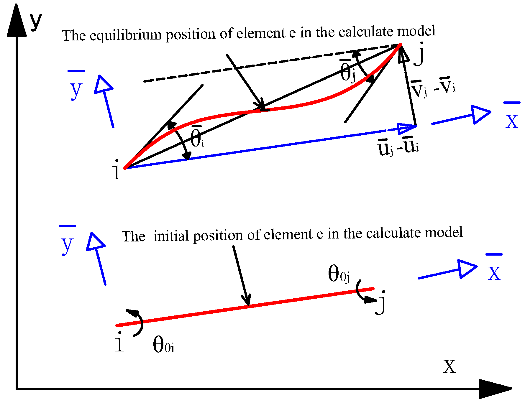
2.2. The Geometric Nonlinear Mechanics Equations of the Staged-Construction Planar Beam Structure

The research object is the two-node planar beam element e, as shown in Figure 1. The cross-sectional area of element e is A, the moment of inertia is I, and the modulus of elasticity is E. Under the action of the equivalent node load P, the deformation occurs from the calculated position to the final equilibrium state.
When element e is installed, the stress-free-state length is l 0 , the stress-free-state curvature at beam i of the beam end is κ i 0 , and the stress-free-state curvature at end j of the beam is κ j 0 . Since the stress-free-state curvature is more abstract in practice, the stress-free-state angle is usually used to reflect this value. Expressed by the beam end angle, the stress-free-state angle at the beam i end is θ i 0 , and the stress-free-state angle at the beam j end is θ j 0 , as shown in Figure 2.
The stress-free-state length and stress-free-state curvature of structural elements are inherent quantities of the structure itself, and will not change with the loading of the structure and the change in the structural system [18]. To change the stress-free-state length and stress-free-state curvature of structural member elements, there must be substantial physical changes to the shape of the elements. For example, if the stress-free-state length of the stay cable is to be reduced, the anchor head of the stay cable end must be artificially pulled out by a tension jack to reduce the length of the stay cable between the anchor points of the beam and tower.
According to the previous section, the geometric nonlinear mechanics equilibrium equation of the completion state of the staged-construction planar beam element in the local coordinate system can be obtained, as shown in the following formula:
( K N e + K σ 0 e ) δ = P e + P 0 e
In the above formula: K N e is the geometric nonlinear full stiffness matrix of the planar beam element, K σ 0 e is the additional stress stiffness matrix of the planar beam element, and P 0 e is the generalized load array of the planar beam element.
In Formula (21), the additional stress stiffness matrix K σ 0 e of the planar beam element structure can be expressed as the following formula:
K σ 0 e = E A ( l l 0 ) l 1 l 0 0 1 l 0 0 0 6 5 l 1 10 0 6 5 l 1 10 0 1 10 2 15 l 0 1 10 l 30 1 l 0 0 1 l 0 0 0 6 5 l 1 10 0 6 5 l 1 10 0 1 10 l 30 0 1 10 2 l 15
In Formula (21), the generalized load array P 0 e of the planar beam element can be expressed by the following formula:
P 0 e = E A l ( l l 0 ) 6 E I l 2 ( θ i 0 + θ j 0 ) 4 E I l θ i 0 + 2 E I l θ j 0 E A l ( l l 0 ) 6 E I l 2 ( θ i 0 + θ j 0 ) 4 E I l θ i 0 2 E I l θ j 0 = E A l ( l l 0 ) E I ( κ j 0 κ i 0 ) l κ i 0 E A l ( l l 0 ) E I ( κ j 0 κ i 0 ) l κ j 0
Assembling Equation (21) in the global coordinate system, the equilibrium equation of the completion state of the staged-construction planar beam element structure considering the geometric nonlinear effect can be obtained, as shown in the following formula:
( K N + K σ 0 ) δ = P + P 0
In Formula (13), K σ 0 represents the effect of the stress-free-state variables on the nonlinear stiffness matrix of the staged-construction planar beam element structure; P0 reflects the effect of the stress-free-state variables change in the element on the external force load array.
The static equilibrium Equation (24) reflects the mechanical equilibrium condition of the completion state of the staged-construction planar beam structure, but the actual construction process is not specified in the equation derivation process. Obviously, when geometric nonlinearity is considered in the calculation, the completion internal force and deformation of the staged-construction planar beam structure are uniquely determined by the following four conditions: (1) The external load, including the location and size of the load reacting in the load array P in the equation; (2) The structural system, including the final geometric configuration of the structure and the structural element parameters E, I, A, etc.; (3) Boundary conditions; (4) The stress-free-state state variables, including the stress-free-state length and the stress-free-state curvature, which will affect P0 and K σ 0 in Equation (24).
For the staged-construction planar beam element structure, when geometric nonlinearity is considered in the calculation, as long as the external load, structural system, boundary conditions, and stress-free-state variable are certain, the completion internal force and displacement are unique, independent of the construction process.
For the planar beam element structure formed in stages, the static equilibrium Equation (24) can be used to directly solve the completion internal force and deformation of the structure, without considering the construction process.
For the staged-construction planar beam element structure, which is different from the planar bar element structure, there is generally a closure segment. In the process of deriving Formula (24), the influence of the closure segment is not considered, so the influence of the closure segment needs to be discussed.
In the above derivation process, the Kirchhoff beam assemblies [34,35] is applied, that is, the normal line of the mid-surface remains perpendicular to the mid-surface after deformation. For the staged-construction beam structure based on this theory, after the element is deformed, the normal on the interface connecting the left and right elements must keep the same direction after deformation [35,36]. For the classical beam element, the rotation of the element normal can be represented by the derivative of the deflection. Therefore, requiring the normal of the element interface to maintain the same direction is actually requiring the first-order derivative of the deflection to be continuous. This can also be seen from the fact that the energy functional of the beam includes the second derivative of the deflection.
To sum up, for a staged-construction planar beam structure with closing sections, in order to make the completion internal force and deformation of the structure the same as the design target state, the installation of closing sections must follow two basic conditions. (1) When the closing section is installed, its stress-free-state variables (stress-free-state length and stress-free-state curvature) must be the same as the design target state (sufficient condition); (2) After the closing section is installed, the first derivative of the deflection at the closing opening must remain continuous (necessary condition). The above two conditions are indispensable, and are called the stress-free-state installation condition of the closing section.

3. Nonlinear Stress-Free-State Forward Analysis Method for Long-Span Cable-Stayed Bridges

In the design of cable-stayed bridges, the completion target state is the ideal structural state, which is generally defined by the designer [11,26,30]. Parameters such as structural geometric information, cable material parameters, and completion cable force can be determined from the design target state.
Suppose the calculation equilibrium equation of the design target state of the cable-stayed bridge is as follows:
( K N + K σ 0 opt ) δ = P + P 0 opt
Among them, P 0 opt and K σ 0 opt are determined by the stress-free-state variables of the elements in the design target state, and the stress-free-state variables are determined according to the internal force state of the elements. It can be seen from the above formula that, in order to make the completion internal force and deformation of the staged-construction cable-stayed bridge equal to the design target state, the stress-free-state variables of each element (beam element and cable element) must be consistent with the design target state. The above are sufficient conditions.
After determining the design target state, the more important task is to analyze the construction and installation stage of the cable-stayed bridge. For cable-stayed bridges with large spans, geometric nonlinearity must be considered in installation calculations. According to the conclusions drawn in Section 1, under the condition of considering geometric nonlinearity, as long as the external load, structural system, boundary conditions, and stress-free-state length and stress-free-state curvature of the element are determined, then the completion internal force and deformation of the staged-construction, long-span cable-stayed bridge is definite and unique.
The following are the four factors that determine the internal force and deformation of the completion state in the installation calculation of the cable-stayed bridge:(1) External load. Although the dead load of the structure is applied in stages during the construction process, the dead load of all elements must be applied when the bridge is finally completed. The size and position of temporary construction loads acting on the structure during construction are changing throughout the construction, but they are all removed when the bridge is completed. Therefore, in the installation calculation, the external load of the cable-stayed bridge is determined when the bridge is completed. (2) Structural system. The structural system of the cable-stayed bridge is changeable during the staged construction, but the structural system must be the structural system required by the design target state when the bridge is completed. (3) Boundary conditions. Like external loads and structural systems, the supporting boundary of the staged-construction cable-stayed bridge must also be consistent with the completion certain target state when the bridge is completed. (4) Element stress-free-state curvature. For the segmental prefabricated and assembled bridge structure, the geometrical shape of the prefabrication on the pedestal should meet the design target stress-free-state curvature requirement. If the segment is cantilever cast, the curvature of the segment when it is not loaded should be controlled by the height difference between the front and rear of the segment during cantilever casting. The purpose of this is to make the stress-free-state curvature of the segment element equal to the design target state.
At the same time, the continuity condition of the elastic curve must be satisfied. This mainly means that the elastic curve cannot have knuckles when the main beam is closed. The continuity of the elastic curve can be realized by adjusting the cable before closing. This is a necessary condition for the final internal forces and deformation of the staged-construction cable-stayed bridge to be equal to the design target state.
After satisfying the above conditions such as external load, structural system, boundary conditions, and element stress-free-state curvature, etc., as long as the stress-free-state length of the cables is equal to the design target state, then the final internal forces and deformation of the staged-construction cable-stayed bridge must automatically approach the completion certain target state defined by the designer.
The stress-free-state variables of the structure is a stable physical quantity. The stress-free-state length and stress-free-state curvature of the main beam element can only be adjusted and set when the element is installed, and the stress-free-state length of the cable-stayed cable can only be changed by tensioning. The stress-free-state variables of the structural element will not change with the structural system and the external load of the structure. The characteristics of the structural stress-free-state state variables provide great convenience for the installation and construction control of the cable-stayed bridge, and also create conditions for the multi-process synchronous operation in the construction of the cable-stayed bridge.
When using the mechanical equilibrium equation of the staged-construction bar system structure, obtained in Section 2, to determine the middle state of construction, the analysis and calculation process is as follows:(1) The stress-free-state length of each stay cable in the design target state specified by the design is calculated. (2) According to the actual construction process of the cable-stayed bridge, the forward installation calculation of the structure is carried out in stages. In the process of the forward installation calculation, each stay cable can be stretched or relaxed multiple times according to the requirements during the construction; however, the stress-free-state length of the stay cable needs to be adjusted to the stress-free-state length of the design target state during the last active tensioning.
If the steel structure cable-stayed bridge or concrete cable-stayed bridge does not consider the effect of concrete shrinkage and creep, the completion state obtained in the second step above must automatically approach the design target state.
All the stay cables and beam segments that make up the cable-stayed bridge are installed in stages according to the stress-free-state variables of the design target state to perform the forward installation calculation, which is called the stress-free-state installation. If the internal force and deformation of the completion state of the structure are the same as the design target state, then the middle state of the construction process of the cable-stayed bridge can be directly obtained without performing the demolition calculation. The above calculation process is called the stress-free-state forward analysis.

4. Application to a Real Bridge

Taking a cable-stayed bridge with a main span of 688 m as an engineering example, the stress-free-state forward analysis was carried out under the condition of geometric nonlinearity.

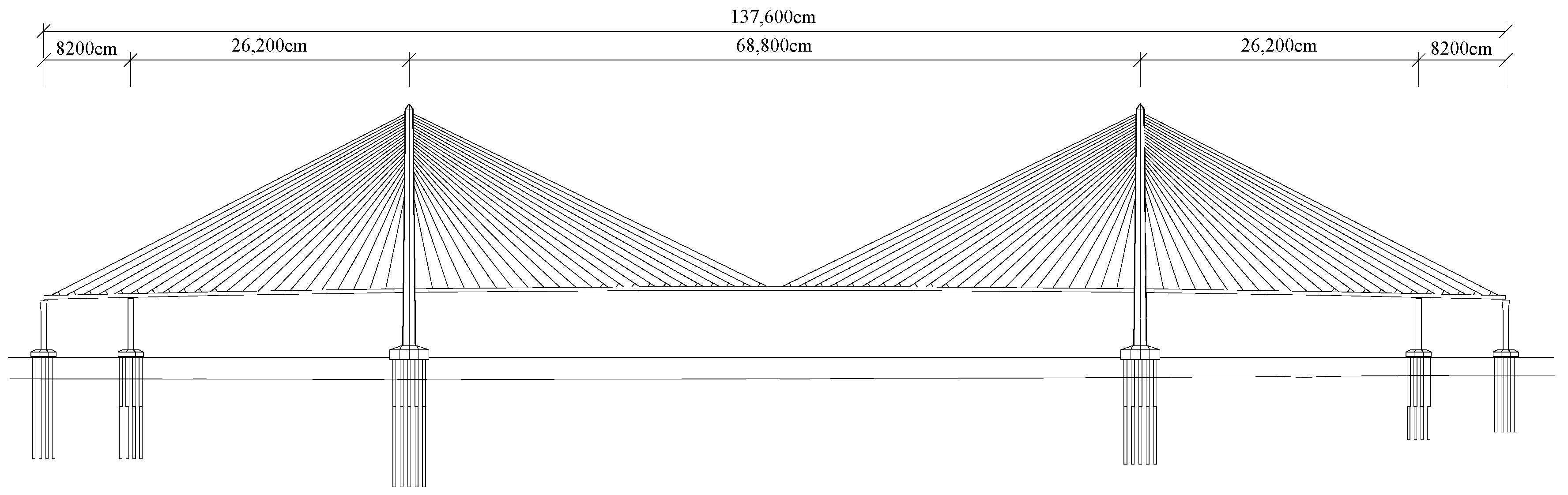
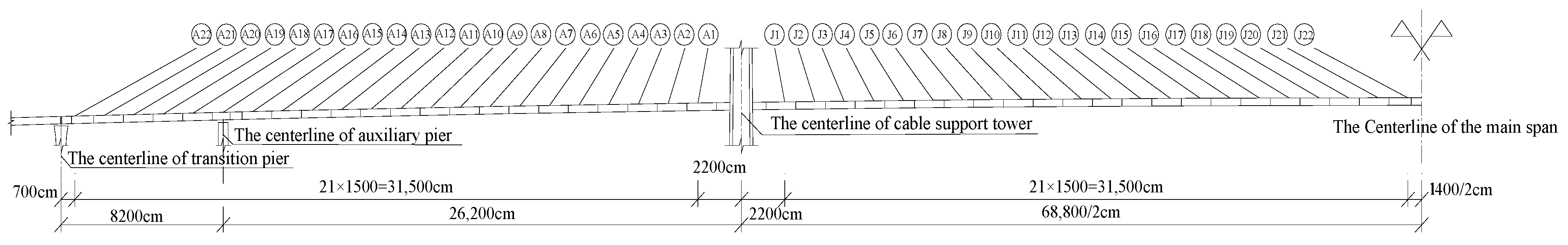
4.1. The Project Overview

This bridge is a five-span continuous semi-floating cable-stayed bridge with double pylons and double cable planes. The span layout of the bridge is 82 + 262 + 688+ 262 + 82 m, as shown in Figure 3. The main beam is a flat, streamline, closed steel box beam, and the stay cables are high-strength, parallel steel wire cables with a standard spacing of 15 m. There are 176 stay cables in the entire bridge, with a maximum length of 376 m and a maximum weight of 26.3 t, as shown in Figure 4. The main tower is a diamond-shaped concrete cable tower with a total height of 226.5 m.
The main beam of the bridge is constructed by deck crane, and the main construction process is shown in Figure 5.

4.2. The Establishment and Analysis of the Nonlinear Stress-Free-State forward Model

According to the actual construction process of the bridge, a staged-construction finite element model considering a geometric nonlinear effect was established to carry out nonlinear stress-free-state forward analysis. In order to simplify the problem, the design configuration of the main beam was used as a reference configuration to establish a finite element model, and the design configuration was taken as the stress-free-state configuration of the main beam.
The following two conditions must be met for the nonlinear stress-free-state forward installation analysis of the bridge: (1) The stress-free-state length of the stay cable determined by the design target state shall be taken as the final control value for calculation and analysis. (2) Compulsory measures are taken when the main beam is closed to ensure that it meets the stress-free-state installation conditions of the closed section, and the compulsory measures are removed after closing.
In order to verify the correctness and superiority of the nonlinear stress-free-state forward analysis, on the basis of satisfying the above two basic conditions, two different construction methods were used for the calculation to verify whether the internal force and deformation of the completion state were consistent with the design target state.
Construction method 1 (sequential operation plan): The bridge is constructed stage by stage. There are three construction stage: Construction stage (1), Erection of beam sections; Construction stage (2), The first tension of the corresponding stay cable; Construction stage (3), The crane moves forward and provides the second tension on the corresponding stay cable. The stress-free-state length of the stay cables is adjusted to the stress-free-state length of the design target state through tensioning.
Construction method 2 (parallel operation plan): The bridge is constructed in parallel by multiple processes. The tensioning of the stay cables is carried out simultaneously with the forward movement of the crane. The stress-free-state length of the stay cables is adjusted to the stress-free-state length of the design target state by one tensioning.
After the construction plan is determined, a large number of construction temporary loads are important uncertain factors in the construction process. In order to more accurately simulate the real construction situation, with the typical temporary load crane as the load variable, the weights of the deck cranes of the two construction methods were different, as shown in the Table 1.
In the actual construction process of long-span cable-stayed bridges, in order to ensure the stress-free-state installation of the closing section of the main beam, a feasible solution would be to take compulsory measures before closing. This measure ensures that the corner of the closing section’s opening relative to the horizontal direction is 0, and the distance of the closing section’s opening is equal to the stress-free-state length of the closing section, as shown in Figure 6. At this time, the closing section is installed, so that it can not only ensure that the closing section is installed in the stress-free-state variables of the design target state, but also ensure that the elastic curve remains continuous.
In order to meet the stress-free-state installation conditions of the closure section, compulsory measures shall be taken when the main beam of the two construction methods are closed. The deformation of the main beam before closing, and after compulsory measures were taken, is shown in Figure 7 and Figure 8.

4.3. Calculation Results

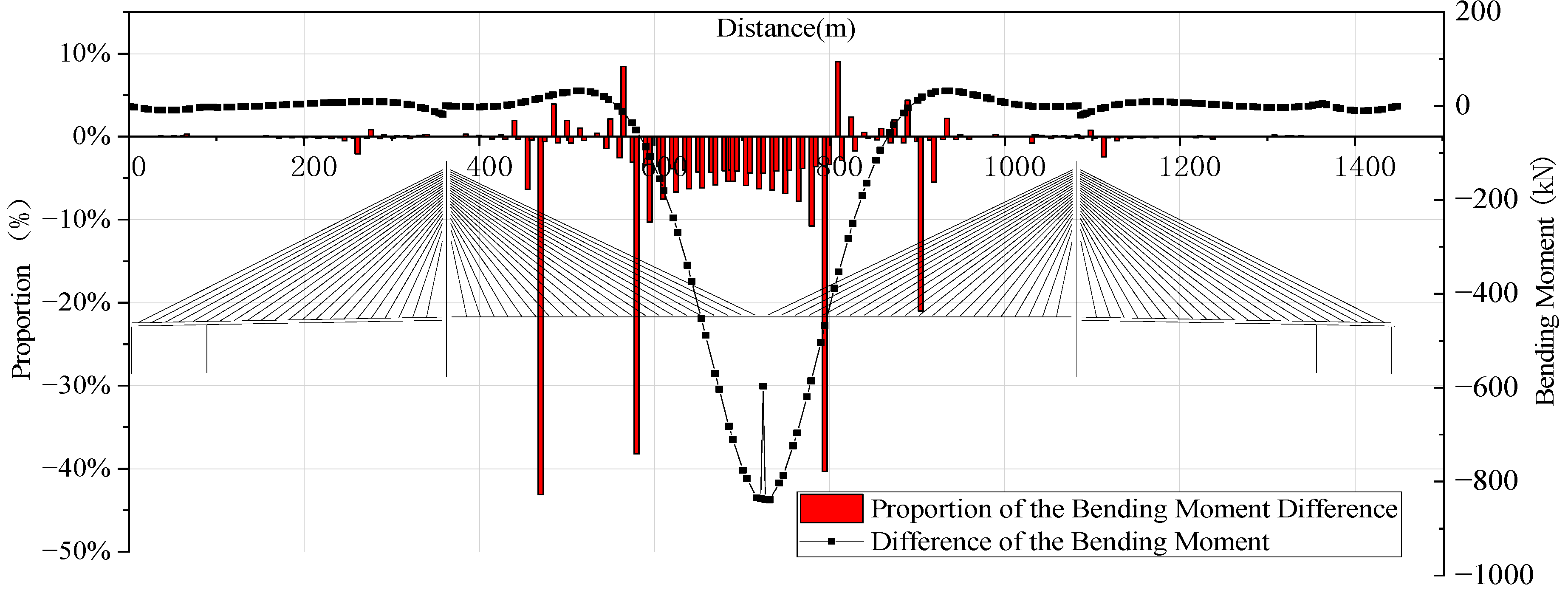
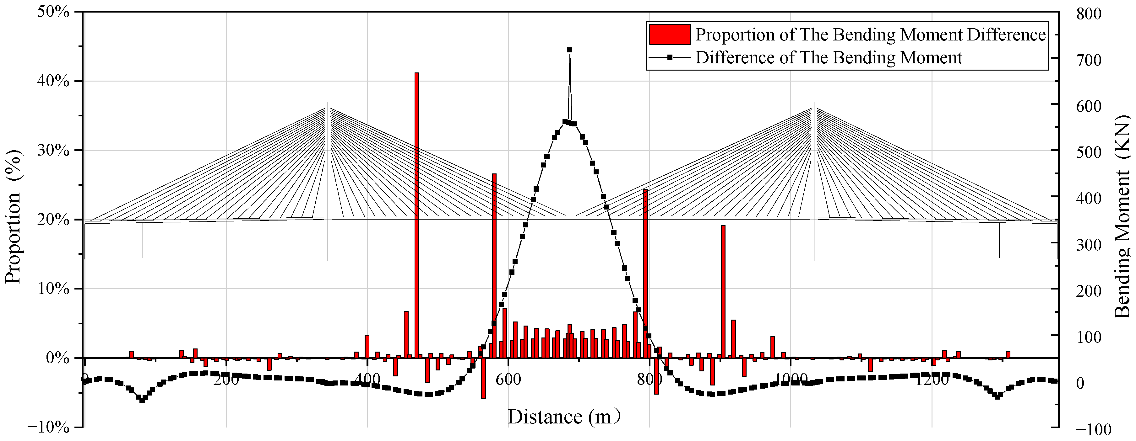
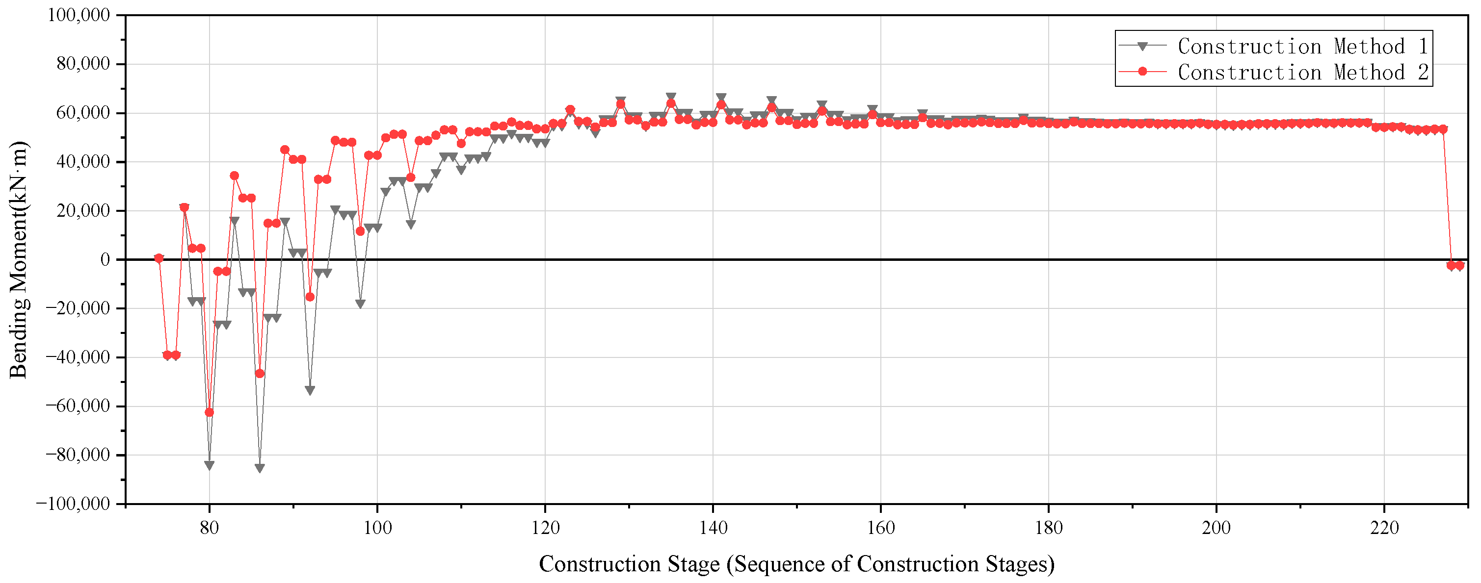
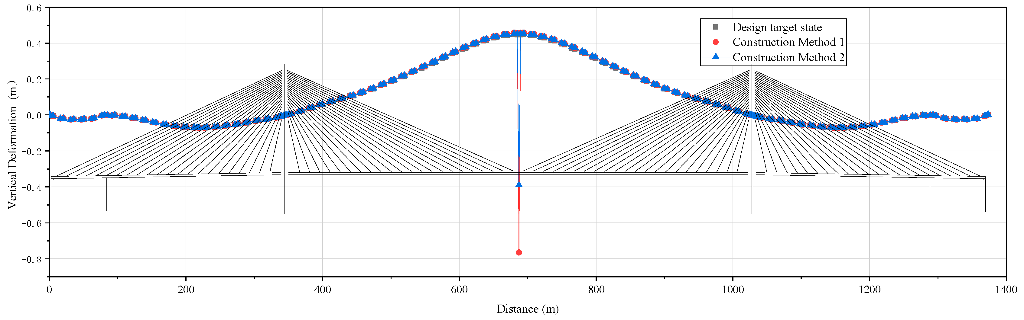
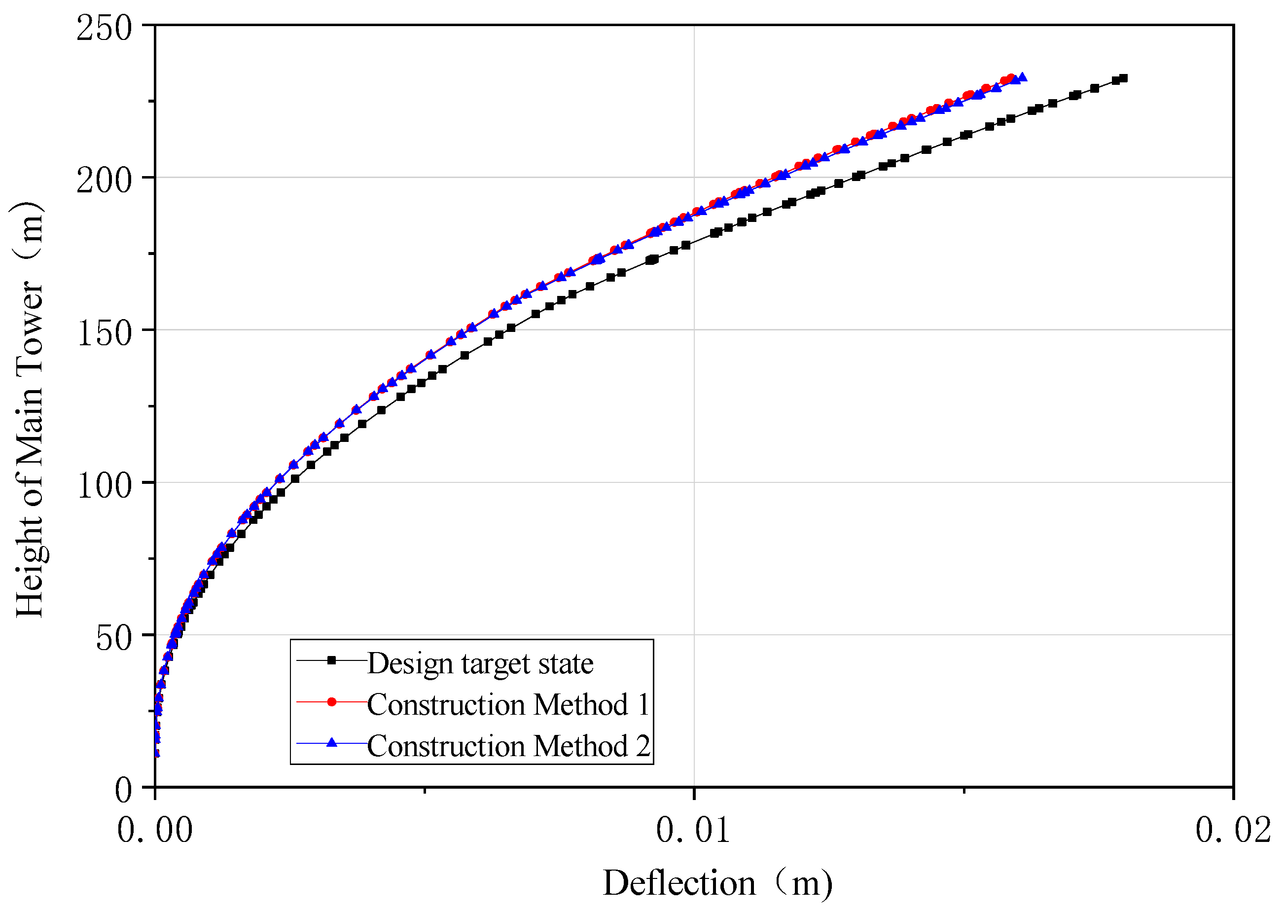
4.3.1. Internal Force and Deformation Calculation Results of the Main Beam

The calculation results of the completion bending moment of the main beam constructed by the two methods are presented in Figure 9. It can be seen from Figure 9 that the completion bending moment of the two different construction methods was highly consistent with the design target state.
The difference between the calculation results of the completion bending moment of the main beam constructed by the two construction methods and the design target state were analyzed, as shown in Figure 10 and Figure 11.
It can be seen from Figure 10 that there was a difference between the completion bending moment of the main beam constructed by method 1 and the design target state. The difference in the rate of the bending moment in the two side spans was within 5%, and the difference was within 50 kN·m. The difference rate in the midspan was basically within 10%, and the difference rate of the individual parts was large, but the difference was within 900 kN·m. The maximum difference rate in the entire bridge occurred at the middle span, which was 470 m away from the support under the tower, reaching −43.1%, but the difference was only 28.2 kN·m. The maximum difference occurred approximately at the mid-point, which was 694 m away from the tower support, reaching −838.9 kN, but the corresponding difference rate was only 4.1%.
It can be seen from Figure 11 that there was a difference between the completion calculation bending moment of the main beam constructed by method 2 and the design target state. The difference rate of the bending moment in the two side spans was within 5%, and the difference was within 50 kN·m. The difference rate in the midspan was basically within 10%, and the difference rate of the individual parts was large, but the difference was within 750 kN·m. The maximum difference rate in the whole bridge occurred at the mid-point, which was 470 m away from the tower support, reaching 41.1%, but the difference was only −27 kN·m. The maximum difference occurred approximately at the mid-point of the midspan, which was 687 m away from the tower support, reaching 717.1 kN, but the corresponding difference rate was only 4.8%.
In order to more clearly explain the change trend in the internal force of the main beam in the process of nonlinear stress-free-state forward analysis, the bending moment value of the main beam at each construction stage at the permanent support point under the cable tower was taken, as shown in Figure 12. It can be seen from the figure that the bending moment change trend in the main beam of the two construction methods was approximately the same and finally converged to the design target state in the process of the bridge construction. However, in a specific construction stage, the bending moment values of the two construction methods were different. This shows that for long-span staged-construction cable-stayed bridges, when the structural system, external loads, and boundary conditions are determined, the internal force and deformation of the main beam in the completion state are only related to the stress-free-state variables of the elements, but have nothing to do with the construction process.
The calculation results of the completion axial force and deformation of the main beam constructed by the two construction methods are shown in Figure 13 and Figure 14. It can be seen from Figure 13 that the completion axial force and deformation of the two different construction methods was highly consistent with the design target state. The maximum difference between the completion axial force of the main beam and the design target state in construction method 1 was 91 kN, and the maximum difference in deformation was 10 mm. The maximum difference between the completion axial force of the main beam and the design target state in construction method 2 was 63 kN, and the maximum difference in deformation was 6 mm. It can be seen that the difference between the completion axial force and deformation of the main beam constructed by the two construction methods and the design target state was very small.
The completion deflection calculation results of the cable tower are shown in Figure 15. The maximum difference between the completion deflection of the cable tower and the design target state in construction method 1 was 2 mm. The maximum difference between the completion deflection of the cable tower and the design target state in construction method 2 was 1.8 mm. The difference was negligible with respect to the tower height of 226.5 m.
Judging from the calculation results of the two different construction methods, only one nonlinear forward calculation was required, and the internal forces and deformations of the main beam and cable tower in the completion state were consistent with the design target state.

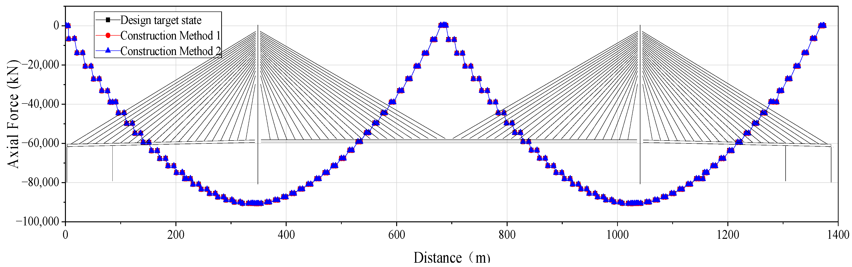
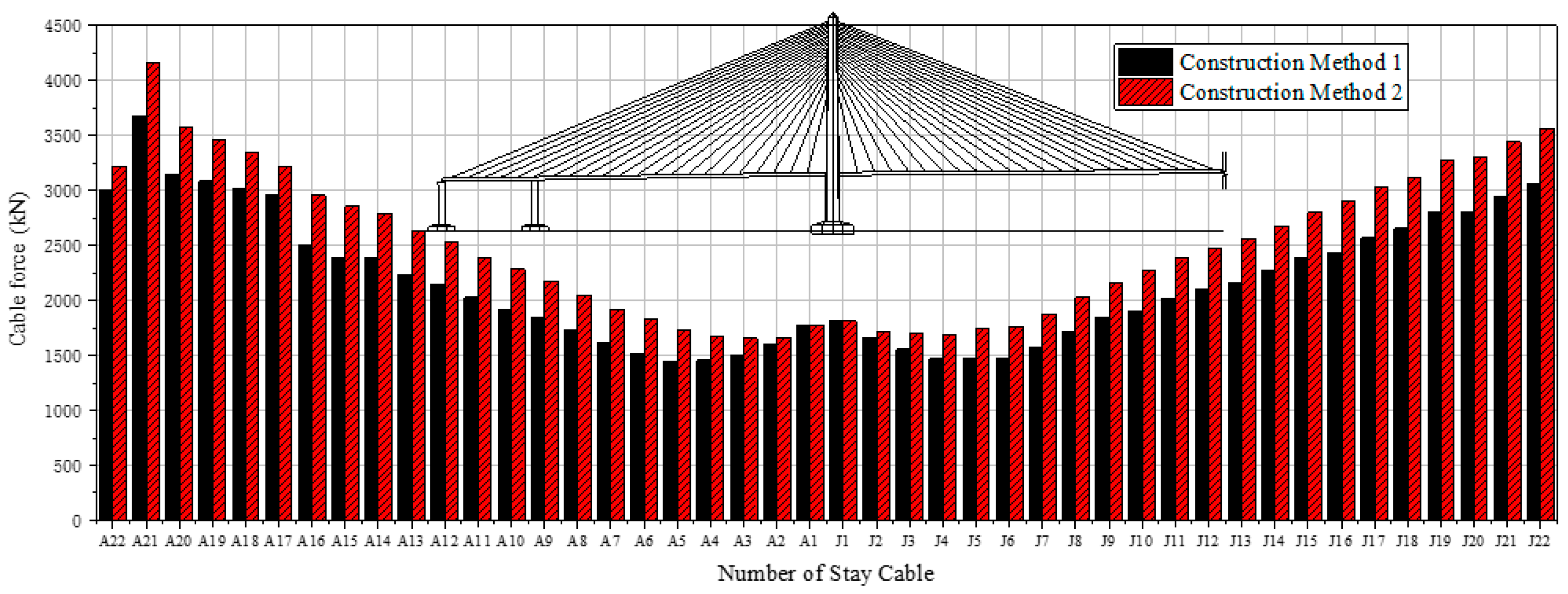
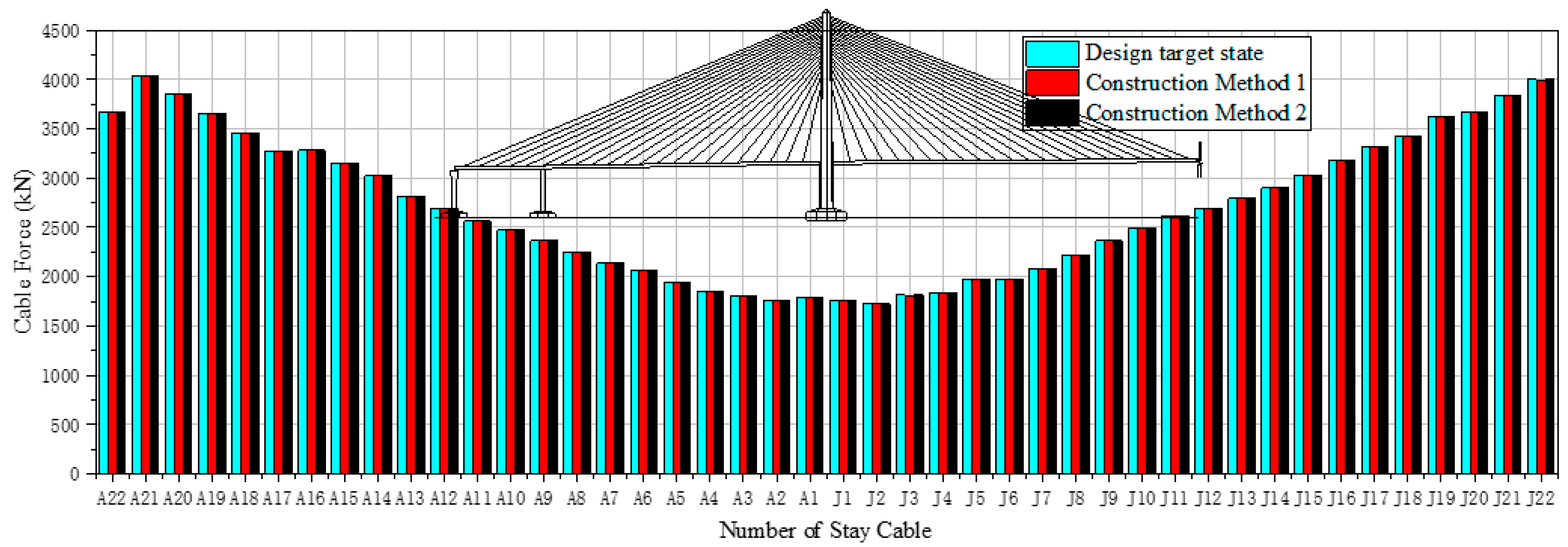
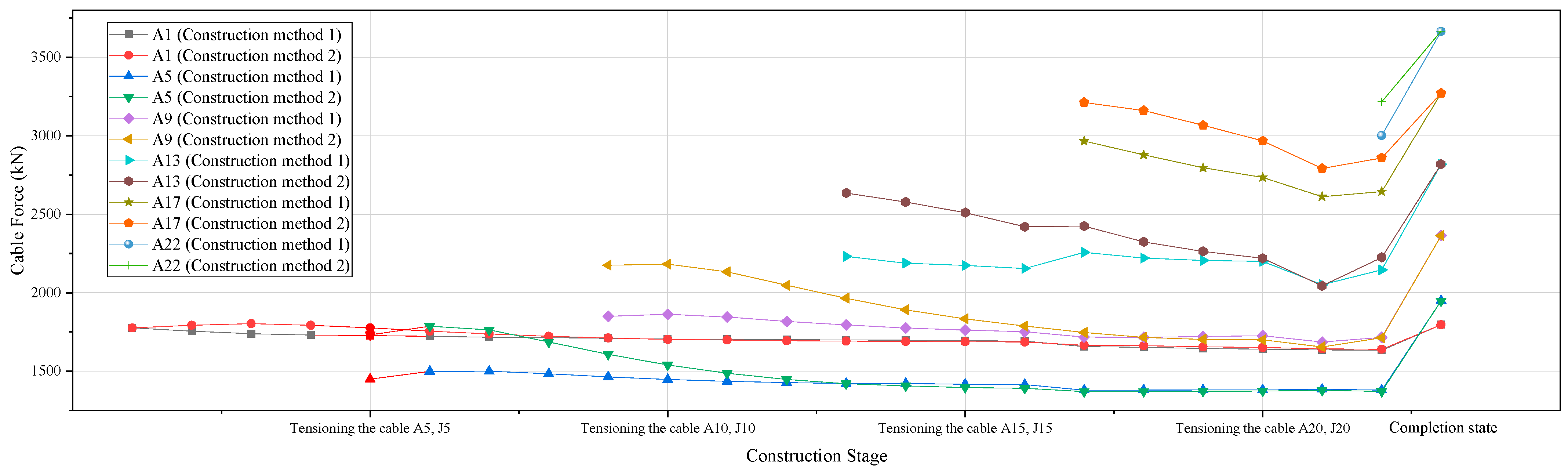
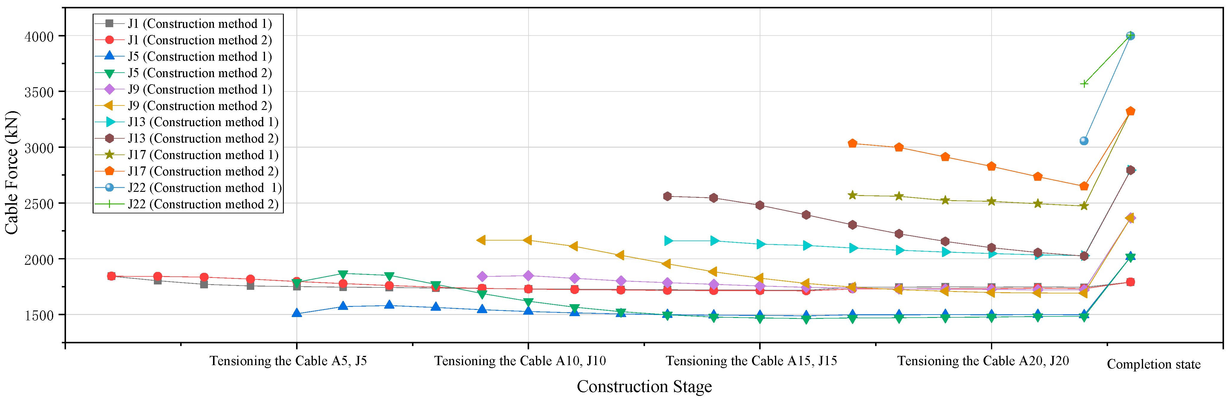
4.3.2. The Force Results of Stay Cables

According to the nonlinear stress-free-state forward analysis method, the calculation results of the construction cable tension force of the two construction methods are shown in Figure 16. The calculation results of the completion cable force are shown in Figure 17. It can be seen from Figure 16 and Figure 17 that the construction cable tension force of construction method 2 was greater than that of construction method 1, but the completion cable force was completely consistent with the design target cable force. This verifies the correctness, reliability, and superiority of the nonlinear stress-free-state forward installation analysis. The reason for the construction cable tension force of construction method 2 being greater than that of construction method 1 was that the weight of the bridge crane in construction method 2 was greater than that in construction method 1.
In order to more clearly explain the change trend in cable force in the process of nonlinear stress-free-state forward analysis, the cable force values of cable A1, cable A5, cable A9, cable A13, cable A17, cable A22, cable J1, cable J5, cable J9, cable J13, cable J17, and cable J22 at each construction stage were taken, as shown in Figure 18 and Figure 19. The change trend in each cable force of the two construction methods was approximately the same and finally converged to the design target cable force. However, in a specific construction stage, the cable force values of the same cable of the two construction methods were different. The calculation results of the cable forces proves that for long-span cable-stayed bridges, when the structural system, external loads, and boundary conditions are determined, the cable force in the completion state is only related to the stress-free-state state length of the cables, and has nothing to do with the construction process.

5. Conclusions

This paper derived the geometrical nonlinear mechanics equilibrium equation of a staged-construction bar system structure based on the minimum potential energy theorem and the basic principle of the stress-free-state control method. Based on the basic principles of the equations obtained above, a new simulation method for long-span cable-stayed bridge construction is proposed. To investigate its reliability and effectiveness, a real cable-stayed bridge with a main span of 688 m was investigated, using different construction methods. The results demonstrated that it had superior performance in the simulation analysis of the construction stage of large-span cable-stayed bridges. Several conclusions can be drawn, as follows:
(1)
According to the minimum potential energy theorem, the geometrical nonlinear mechanics equilibrium equation of a staged-construction bar system structure was obtained. The equation reflects the influence of the change in the stress-free-state variables on the completion state of the structure. It can be seen that, in the case of the same structural system, external loads, and boundary conditions, the determinant of the completion state of the different construction methods was the stress-free-state variables of the structural elements.
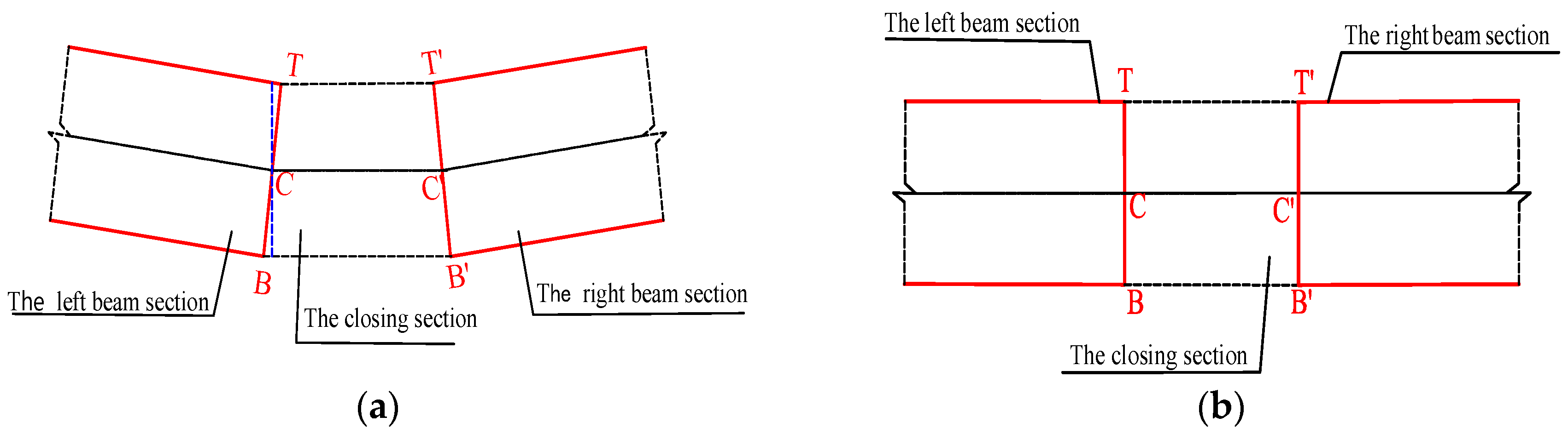
(2)
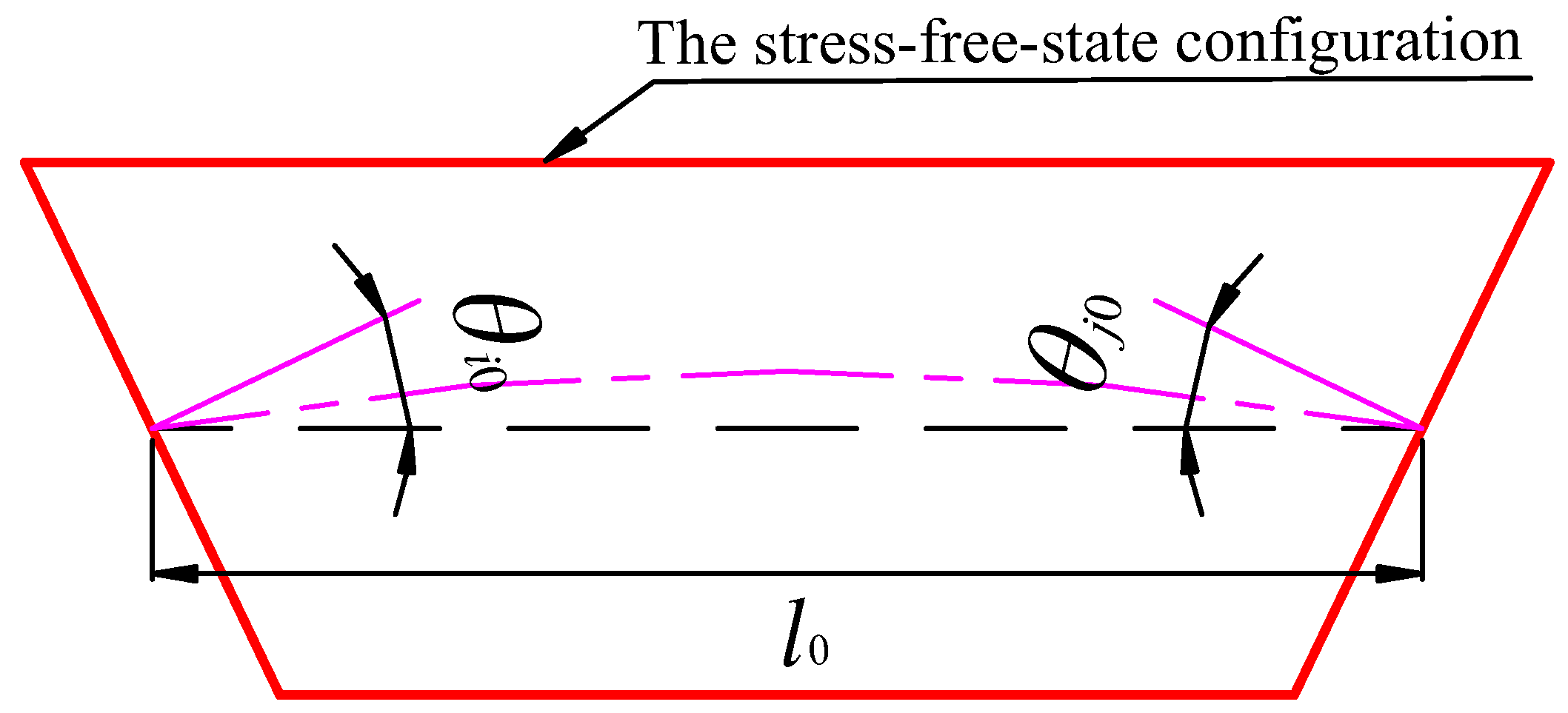
The geometrical nonlinear equilibrium mechanics equation of the staged-construction planar beam structure was obtained. The specific expressions of the additional stress stiffness matrix and the generalized load array in the equation have been given. From the analysis of the equation, it can be seen that for the planar beam structure, when the structural system, external loads, boundary conditions, and stress-free-state variables were determined, the internal force and deformation were unique in the completion state and had nothing to do with the construction process experienced. For the staged-construction planar beam structure with a closing section, the stress-free-state installation condition of closing section was obtained from the analysis of the geometrical condition that the equilibrium equation holds.
(3)
Combined with the construction characteristics of cable-stayed bridges, according to the mechanical equilibrium equation of the staged-construction bar system, a new simulation method of long-span cable-stayed bridge construction is proposed. This is called stress-free-state forward analysis. Considering the influence of the geometric nonlinearity of the long-span cable-stayed bridge, this method can directly obtain the intermediate process state of the cable-stayed bridge construction without performing stage-by-stage demolition calculations. With this method, only one forward calculation is required for the internal force and deformation of the final structural state to reach the design target state.
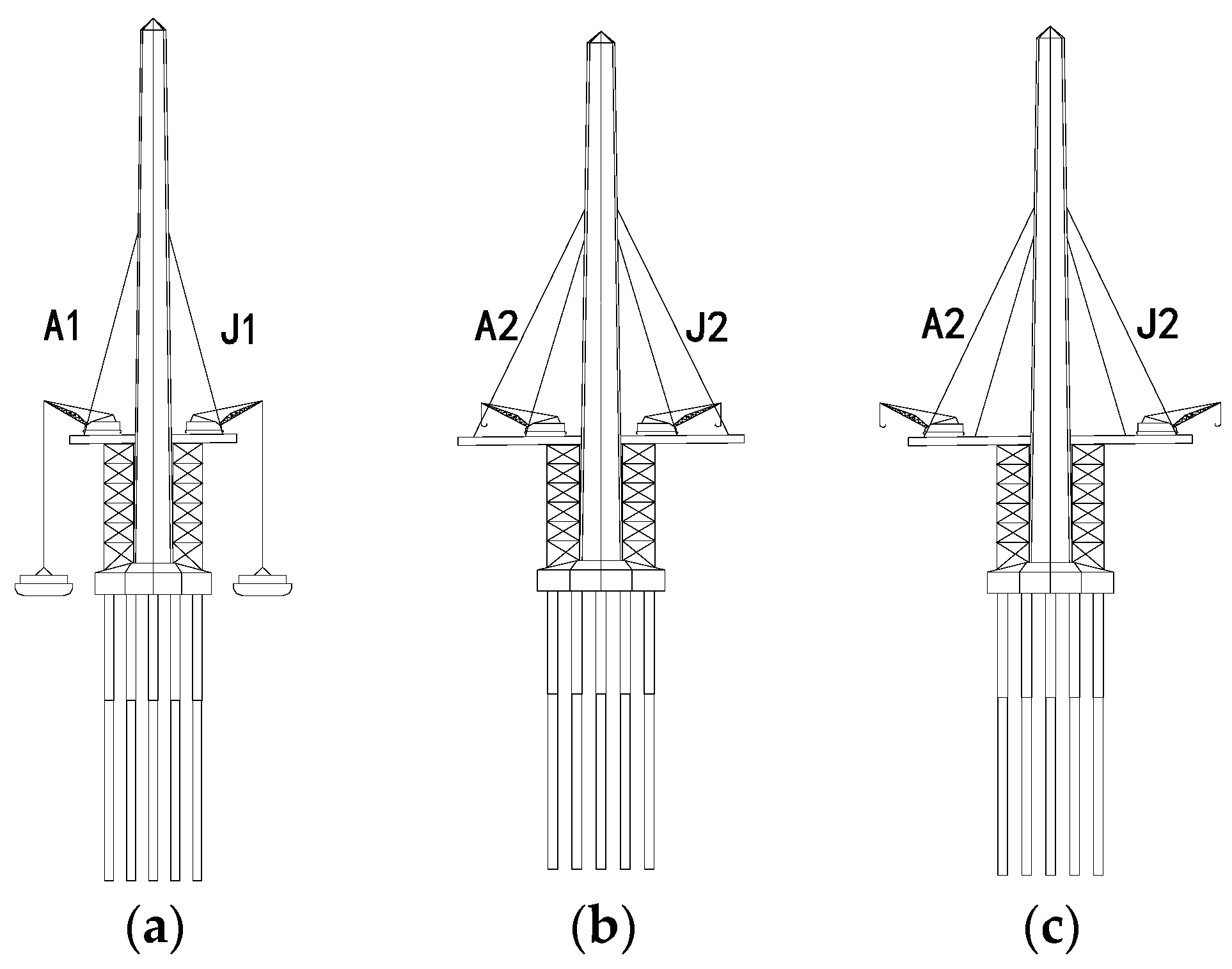
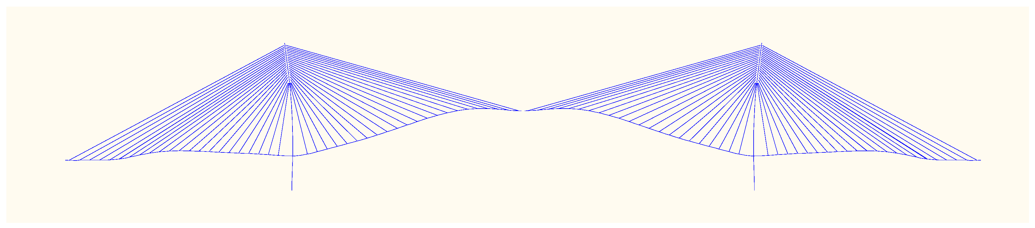
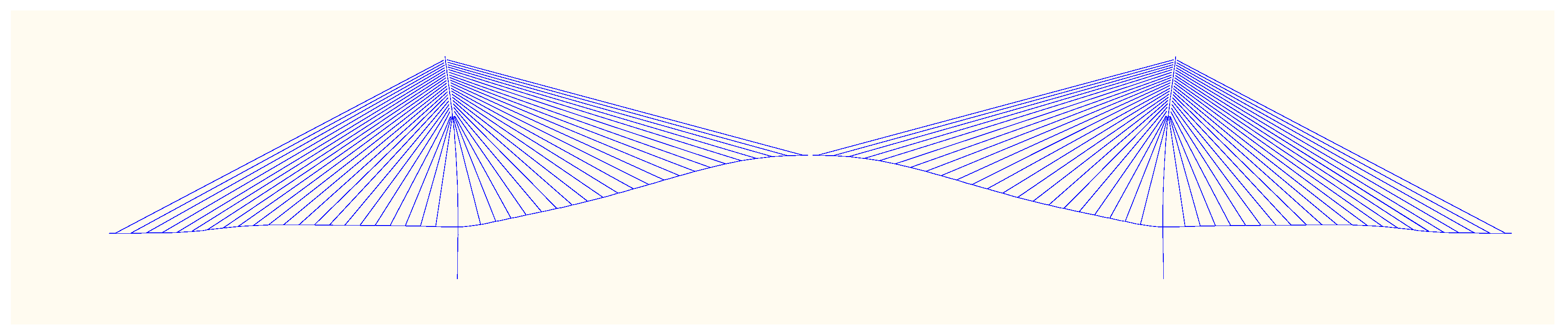
(4)
Taking the cable-stayed bridge with the main span of 688 m as an example, considering the geometric nonlinearity, the construction process of the two different construction methods of the bridge was calculated using the stress-free-state forward analysis method. The calculation results showed that although the cable force in each construction stage of the two construction methods was different, the change trend was approximately the same, and the cable force in the completion stage converged to the design target state. The calculation results of the internal force and deformation of the main beam in the completion state were slightly different from the design target state. The results verify the reliability of the stress-free-state forward analysis method used in the simulation analysis of the construction stage of long-span cable-stayed bridges. At the same time, the geometric nonlinear equilibrium equation mechanics equations of the staged-construction bar system structure proposed in this paper were also verified by the example. This study provides a theoretical basis and reference for the popularization and application of the stress-free-state forward analysis method for cable-stayed bridges.
This study illustrates that the stress-free-state forward analysis method can efficiently complete the construction simulation calculation of long-span cable-stayed bridges, and can replace the traditional incremental analysis method. This method can be determined as a meaningful simulation method in the construction simulation calculation of long-span cable-stayed bridges. Compared with the traditional incremental analysis method, the theoretical concept of this method is clear, but it needs to understand the new abstract physical variable of the stress-free-state variable in the calculation process.

Author Contributions

Conceptualization, writing—review and editing S.W.; supervision, funding acquisition X.W.; data curation W.G.; validation, formal analysis Z.Z. All authors have read and agreed to the published version of the manuscript.

Funding

This research was supported by the Science and Technology Innovation Project of Yangling Vocational and Technical College, grant number ZK22–26; and this research was funded by the Key R&D Program of Shaanxi Province, grant number 2023-YBNY-042, 2023-YBNY-223.

Data Availability Statement

Some or all data, models, or codes that support the findings of this study are available from the corresponding author upon reasonable request.

Conflicts of Interest

The authors declare no conflict of interest.

References

  1. Lin, K.; Xu, Y.L.; Lu, X.; Guan, Z.; Li, J. Digital twin-based collapse fragility assessment of a long-span cable-stayed bridge under strong earthquakes. Autom. Constr. 2021, 123, 103547. [Google Scholar] [CrossRef]
  2. Sampaio, A.Z.; Martins, O.P. The application of virtual reality technology in the construction of bridge: The cantilever and incremental launching methods. Autom. Constr. 2014, 37, 58–67. [Google Scholar] [CrossRef]
  3. Yao, Y.; Yan, M.; Bao, Y. Measurement of cable forces for automated monitoring of engineering structures using fiber optic sensors: A review. Autom. Constr. 2021, 126, 103687. [Google Scholar] [CrossRef]
  4. Lee, Y.-C.; Shariatfar, M.; Rashidi, A.; Lee, H.W. Evidence-driven sound detection for prenotification and identification of construction safety hazards and accidents. Autom. Constr. 2020, 113, 103127. [Google Scholar] [CrossRef]
  5. Crespi, P.; Zucca, M.; Valente, M.; Longarini, N. Influence of corrosion effects on the seismic capacity of existing RC bridges. Eng. Fail. Anal. 2022, 140, 106546. [Google Scholar] [CrossRef]
  6. Innocenzi, R.D.; Nicoletti, V.; Arezzo, D.; Carbonari, S.; Gara, F.; Dezi, L. A Good Practice for the Proof Testing of Cable-Stayed Bridges. Appl. Sci. 2022, 12, 3547. [Google Scholar] [CrossRef]
  7. Nicoletti, V.; Martini, R.; Carbonari, S.; Gara, F. Operational Modal Analysis as a Support for the Development of Digital Twin Models of Bridges. Infrastructures 2023, 8, 24. [Google Scholar] [CrossRef]
  8. Hou, S.; Dong, B.; Wang, H.; Wu, G. Inspection of surface defects on stay cables using a robot and transfer learning. Autom. Constr. 2020, 119, 103382. [Google Scholar] [CrossRef]
  9. Kim, D.; Kwak, Y.; Sohn, H. Accelerated cable-stayed bridge construction using terrestrial laser scanning. Autom. Constr. 2020, 117, 103269. [Google Scholar] [CrossRef]
  10. Abu Dabous, S.; Feroz, S. Condition monitoring of bridges with non-contact testing technologies. Autom. Constr. 2020, 116, 103224. [Google Scholar] [CrossRef]
  11. Wang, X.; Wang, H.; Sun, Y.; Mao, X.; Tang, S. Process-independent construction stage analysis of self-anchored suspension bridges. Autom. Constr. 2020, 117, 103227. [Google Scholar] [CrossRef]
  12. Li, T.; Liu, Z. An improved continuum model for determining the behavior of suspension bridges during construction. Autom. Constr. 2021, 127, 103715. [Google Scholar] [CrossRef]
  13. Wu, C.; Wu, P.; Wang, J.; Jiang, R.; Chen, M.; Wang, X. Ontological knowledge base for concrete bridge rehabilitation project management. Autom. Constr. 2021, 121, 103428. [Google Scholar] [CrossRef]
  14. Kim, H.-J.; Won, D.H.; Kang, Y.-J.; Kim, S. Structural stability of cable-stayed bridges during construction. Int. J. Steel Struct. 2017, 17, 443–469. [Google Scholar] [CrossRef]
  15. Jin, S.-S.; Jeong, S.; Sim, S.-H.; Seo, D.-W.; Park, Y.-S. Fully automated peak-picking method for an autonomous stay-cable monitoring system in cable-stayed bridges. Autom. Constr. 2021, 126, 103628. [Google Scholar] [CrossRef]
  16. Walther, R. Cable Stayed Bridges, 2nd ed.; Thomas Telford: London, UK, 1999. [Google Scholar]
  17. Oh, B.K.; Park, H.S.; Glisic, B. Prediction of long-term strain in concrete structure using convolutional neural networks, air temperature and time stamp of measurements. Autom. Constr. 2021, 126, 103665. [Google Scholar] [CrossRef]
  18. Qin, S.; Wei, K.; Qin, J.; Yuan, R.; Xu, L.; Dan, Q. Stress-free-state based structural analysis and construction control theory for staged construction bridges. Adv. Bridge Eng. 2020, 1, 1. [Google Scholar] [CrossRef]
  19. Wang, H.; Tang, T.; Zheng, H. Analysis of cable-stayed bridges during construction by cantilever method. Comput. Struct. 2004, 82, 329–346. [Google Scholar] [CrossRef]
  20. Pipinato, A.; Pellegrino, C.; Modena, C. Structural analysis of the cantilever construction process in cable-stayed bridges. Period. Polytech. Civ. Eng. 2012, 56, 141–166. [Google Scholar] [CrossRef] [Green Version]
  21. Behin, Z. Erection Analysis of Cable-Stayed Bridges. PhD Thesis, Department of Civil Engineering, University of Alberta, Edmonton, AB, Canada, 1990. [Google Scholar]
  22. Behin, Z.; Murray, D. A substructure-frontal technique for cantilever erection analysis of cable-stayed bridges. Comput. Struct. 1992, 42, 145–157. [Google Scholar] [CrossRef]
  23. Reddy, P.; Ghaboussi, J.; Hawkins, M. Simulation of construction of cable.Stayed bridges. J. Bridge Eng. 1999, 4, 249–257. [Google Scholar] [CrossRef]
  24. Farre-Checa, J. Simulation of Cantilever Construction of Cable-Stayed Bridges Taking into Account Time Dependent Phenomena. Master’s Thesis, KTH, School of Architecture and the Built Environment (ABE), Stockholm, Sweden, 2017. [Google Scholar]
  25. Wang, X.; Frangopol, D.M.; Dong, Y.; Lei, X.; Zhang, Y. Novel technique for configuration transformation of 3D curved cables of suspension bridges: Application to the Dongtiao River Bridge. J. Perform. Constr. Facil. 2018, 32, 04018045. [Google Scholar] [CrossRef]
  26. Lozano-Galant, J.; Paya-Zaforteza, I.; Xu, D.; Turmo, J. Direct simulation of the tensioning process of cable-stayed bridges. Comput. Struct. 2013, 121, 64–75. [Google Scholar] [CrossRef]
  27. Qin, S. Unstressed state control method for bridges constructed in stages. Bridge Construct. 2008, 1, 8–14. [Google Scholar]
  28. Qin, S. Application of unstressed state control method to calculation for erection of cable-stayed bridge. Bridge Construct. 2008, 2, 13–16. [Google Scholar]
  29. Zhang, H.H.; Sun, N.N.; Wang, P.Z.; Liu, M.H.; Li, Y. Optimization of Cable Force Adjustment in Cable-Stayed Bridge considering the Number of Stay Cable Adjustment. Adv. Civ. Eng. 2020, 2020, 4527309. [Google Scholar] [CrossRef]
  30. Sharry, T.; Guan, H.; Nguyen, A.; Oh, E.; Hoang, N. Latest advances in finite element modelling and model updating of cable-stayed bridges. Infrastructures 2022, 7, 8. [Google Scholar] [CrossRef]
  31. Farré-Checa, J.; Komarizadehasl, S.; Ma, H.; Lozano-Galant, J.; Turmo, J. Direct simulation of the tensioning process of cable-stayed bridge cantilever construction. Autom. Constr. 2022, 137, 104197. [Google Scholar] [CrossRef]
  32. Morán, A.; Oñate, E.; Miquel, J. A general procedure for deriving symmetric expressions for the secant and tangent stiffness matrices in finite element analysis. Int. J. Numer. Methods Eng. 1998, 42, 219–236. [Google Scholar] [CrossRef]
  33. Jian, L.; Yun, T.; Yumei, L. Stiffness matrix of nonlinear FEM equilibrium equation. Procedia Eng. 2012, 29, 3698–3702. [Google Scholar] [CrossRef] [Green Version]
  34. Greco, L.; Scrofani, A.; Cuomo, M. A non-linear symmetric G1-conforming Bézier finite element formulation for the analysis of Kirchhoff beam assemblies. Comput. Methods Appl. Mech. Eng. 2021, 387, 114176. [Google Scholar] [CrossRef]
  35. Schulz, M.; Böl, M. A finite element formulation for a geometrically exact Kirchhoff–Love beam based on constrained translation. Comput. Mech. 2019, 64, 1155–1175. [Google Scholar] [CrossRef]
  36. Greco, L.; Cuomo, M.; Castello, D.; Scrofani, A. An updated Lagrangian Bézier finite element formulation for the analysis of slender beams. Math. Mech. Solids 2022, 27, 2110–2138. [Google Scholar] [CrossRef]
Figure 1. The completion state of the planar beam element e (The blue part: the local coordinate system of the element; The red part: the configuration of the beam element).
Buildings 13 01735 g001
Figure 2. The stress-free-state configuration of planar beam element e.
Buildings 13 01735 g002
Figure 3. The general layout of main bridge.
Buildings 13 01735 g003
Figure 4. The general layout of stay cables (A1–A22:The number of side span stay cable; J1–J22: The number of the mid-span stay cable).
Buildings 13 01735 g004
Figure 5. The construction sequence of the standard segment. (a) Erection of beam sections, (b) Tension of stay cables, (c) Crane moves forward.
Buildings 13 01735 g005
Figure 6. The stress-free-state installation of the closure section (T: The top of the closing section; B: The bottom of the closing section; C: The center of the closing section). (a) The initial state posture, (b) The stress-free-state installation posture.
Buildings 13 01735 g006
Figure 7. The deformation of the main beam constructed by method 1 before closing.
Buildings 13 01735 g007
Figure 8. The deformation of the main beam constructed by method 2 before closing.
Buildings 13 01735 g008
Figure 9. The completion bending moment of main beam constructed by two methods.
Buildings 13 01735 g009
Figure 10. The bending moment difference in the main beam constructed by method 1.
Buildings 13 01735 g010
Figure 11. The bending moment difference in the main beam constructed by Method 2.
Buildings 13 01735 g011
Figure 12. The bending moment change trend in the main beam constructed by two methods in the construction process.
Buildings 13 01735 g012
Figure 13. The completion axial force of main beam constructed by the two methods.
Buildings 13 01735 g013
Figure 14. The completion deformation of main beam constructed by two methods in the completion state.
Buildings 13 01735 g014
Figure 15. The completion deflection of the cable tower of the two methods.
Buildings 13 01735 g015
Figure 16. The construction cable tension force of the two methods.
Buildings 13 01735 g016
Figure 17. The completion cable force of the two methods.
Buildings 13 01735 g017
Figure 18. Variation trend in cable force of side-span stay cables of the two methods.
Buildings 13 01735 g018
Figure 19. Variation trend in cable force of mid-span stay cables of the two methods.
Buildings 13 01735 g019
Table 1. The crane weight of two construction methods.
The Crane WeightFront Axle Weight (kN)Rear Axle Weight (kN)
The Construction Method
Construction method 1948.651
Construction method 21948.61051
Disclaimer/Publisher’s Note: The statements, opinions and data contained in all publications are solely those of the individual author(s) and contributor(s) and not of MDPI and/or the editor(s). MDPI and/or the editor(s) disclaim responsibility for any injury to people or property resulting from any ideas, methods, instructions or products referred to in the content.

