Article

Transfer Length and Prestress Losses of a Prestressed Concrete Box Girder with 18 mm Straight Strands

1
School of Civil Engineering and Architecture, Wuhan Institute of Technology, Wuhan 430205, China
2
Key Laboratory of Transport Industry of Bridge Detection Reinforcement Technology, Chang’an University, Xi’an 710064, China
3
Railway Engineering Research Institution, China Academy of Railway Sciences Corporation Limited, Beijing 100081, China
4
Hubei Muzhi Jun Engineering Materials Corporation Limited, Ezhou 436043, China
*
Author to whom correspondence should be addressed.
Buildings 2023, 13(8), 1939; https://doi.org/10.3390/buildings13081939
Submission received: 30 June 2023 / Revised: 14 July 2023 / Accepted: 27 July 2023 / Published: 30 July 2023
(This article belongs to the Special Issue Latest Advances of Green Concrete Technology in Civil Engineering)

Abstract

:
Despite the potential advantages of 18 mm strands, the limited research on the behavior of girders with larger-diameter strands hinders the application in bridges. Transfer length and prestress losses are two important indicators. In this research, a 32.6 m long prestressed concrete box girder with 18 mm straight strands and 15 mm harped strands was produced, and the transfer length and the prestress losses were studied. The transfer length was calculated based on the existing equations in codes and previous research. Three beam specimens were fabricated, and strain gauges were pasted on the concrete surface to measure the transfer length of 18 mm strands. It indicated that the average measured transfer length was 700 mm. This value was smaller than the transfer lengths predicted by AASHTO LRFD 2017 and ACI 318-19, while Mitchell’s equation offered the closest prediction to the average measured transfer length. Additionally, the prestress losses at different stages were evaluated. A one-end stressing test was conducted to analyze the effect of strand harping on the loss of tensile force. In comparison with the actual measured loss based on the concrete strain and the longitudinal shortening, the instantaneous prestress loss calculated using the AASTHO LRFD 2017 alternative equation was appropriate. The time-dependent prestress losses due to shrinkage, creep, and relaxation were predicted using two different methods addressed in AASHTO LRFD 2017. The time-dependent predicted losses of 69.2 MPa at 28 d using the refined method were 37% higher than the measured losses 47.4 MPa at 28 d, indicating an overestimation of AASHTO LRFD 2017. The accumulation of the total losses over time revealed that the prestress losses developed in the first two months occupied the majority of the total losses in the long term. The research may provide guidelines for the design of a pretensioned concrete box girder with 18 mm strands.

1. Introduction

In most pretensioned concrete members in bridge engineering, Grade 186,015 mm prestressed strands are used. Engineers have been trying to raise the capacity of prestressing strands, contributing to larger prestressing forces. In recent years, 18 mm strands have been produced and applied into bridge engineering. Compared with the 15 mm strands, the nominal breaking force of 18 mm strands increased by more than 35%. By replacing lower capacity strands with higher capacity strands, the prestressing force becomes much larger, or the number of strands can be reduced, and the layout of strands become more flexible. With fewer prestressing strands, less time is spent on placing and stressing strands. Thus, the production efficiency of prestressed concrete girders is improved.
The first bridge in the United States to use 18 mm strands was the Pacific Street Bridge located on I-680 in Omaha [1]. Ma et al. [2] conducted research on the application of 18 mm strands in AASHTO-PCI BT girders and provided corresponding design guidelines. In 2015, a nationwide survey on the use of 18 mm strands in pretensioned girders was performed on all state transportation departments, and only the application in two pretensioned girder bridges in Nebraska were reported [3]. AASHTO LRFD 2017 [4] only provides guidance for the application of strands with a diameter not greater than 15 mm. As for the application of larger-diameter strands, there are two main concerns about safety. One is that no damage occurs during fabrication and the other is the durability in the long term. In fact, the application of 18 mm strands in pretensioned concrete bridge girders is still very limited. Jiang et al. [5] introduced the detailed production process of a box girder using 18 mm strands. Based on the monitoring and analysis of the hydration effect on the development of strand tensile stresses over time, appropriate detension timing was suggested.
Transfer length is an important section location where the stress of a prestressed girder shall be checked to ensure safety and durability. As demonstrated by Russell et al. [6], an inaccurate prediction of transfer length might result in a poor estimation of effective prestress, even causing cracks and bond failure near the beam end. Song et al. [7] measured the transfer length of 18 mm strands and compared the measured values with the calculation results based on the equations of different codes. Jin et al. [8] studied the effects of several parameters on the transfer length of high-strength strands, and the measured transfer length of high-strength strands was compared with the transfer length predicted by previously proposed equations. Dang et al. [9,10,11] systematically measured a large number of transfer lengths while studying the bonding performance of 18 mm strands. Jiang et al. [12,13] conducted a study on the transfer length of 18 mm strands with pull-out tests, in which the failure mode, the relationship between the slip of strand and the pull-out force, and the relationship between the embedment length and the transfer length were analyzed.
Additionally, when it comes to the long-term behavior of prestressed girder, it is essential to understand time-dependent prestress losses which are affected by multiple factors. Although prestress losses may not weaken the ultimate capacity of the prestressed girder, an inappropriate estimation could lead to an unfavorable service condition of the girder or an uneconomical design. Jiang et al. [14] studied the performance of an AASHTO Type-I girder using 18 mm strands, focusing on the prestress losses over time. Garber et al. [15] optimized the estimation process of prestress losses and proposed a procedure for predicting time-dependent prestress losses. Mohebbi et al. [16] studied the time-dependent deformations of ultra-high-performance concrete through full-scale tests and proposed a model for prestress losses. Almohammedi et al. [17] examined the prestress losses in AASHTO Types II, III, IV, and VI girders, comparing the measured prestress losses with the predicted prestress losses. In the field test, dynamic nondestructive methods may be unsuitable since the fundamental frequency is an uncertain indicator of prestress losses [18]. Bonopera and Chang [19] proposed a novel method for identifying residual prestressing force in simply supported girder bridges. Bagge et al. [20,21] introduced in situ approaches in conjunction with finite element analysis for a multi-span continuous girder bridge. These studies showed the difference between the measured prestress losses and the design prestress losses.
In China, box girders are extensively used in bridges. However, there is a lack of research on the behavior of box girders with 18 mm strands, hindering the application of these larger capacity strands. In this paper, the transfer length and the prestress losses of a prestressed concrete box girder using 18 mm strands were investigated. Three prestressed concrete beam specimens were fabricated, and the transfer length of 18 mm strands was measured based on the distribution of concrete surface strains at the beam end. The measured transfer lengths were compared with the predicted values using the existing equations in codes or the previous research. The experimental test results of the transfer length of 18 mm strands may be used for the subsequent design. Additionally, a gigantic pretensioned concrete box girder with 18 mm straight strands and 15 mm harped strands was produced in the factory. The instantaneous prestress loss due to elastic shortening and the time-dependent prestress losses within 28 days after strands detension were analyzed based on the measurement of concrete strains at two typical sections. The development of total prestress losses over time was also predicted in accordance with AASHTO LRFD 2017. It showed that the prediction of instantaneous prestress loss using AASHTO LRFD 2017 was appropriate, while it overestimated the time-dependent prestress losses due to concrete shrinkage and creep.

2. Details of a Prestressed Box Girder and Material Properties

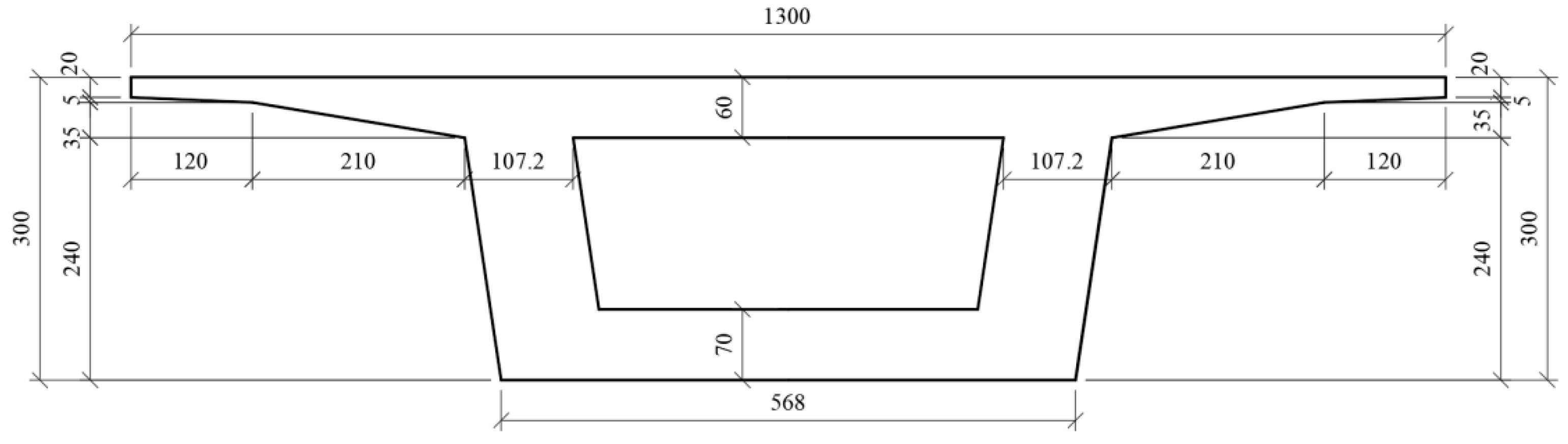
2.1. Section Dimensions

In this project, an experimental test was conducted on a 32.6 m long box girder fabricated in a factory. The dimensions of the box girder are shown in Figure 1 and Figure 2. In the primary design, the conventional 15 mm strands were utilized, of which there were 225 straight strands in the bottom flange and 56 harped strands in the web. However, this design would have resulted in a small spacing between strands, which would have been unfavorable for fabrication. With thoughtful calculation, the designer replaced all 15 mm straight stands with 18 mm stands. In this way, the number of straight stands decreased to 162, and the minimum spacing was 57 mm, slightly larger than the conventional 50 mm strand spacing.

2.2. Material Properties

In this project, Grade 186,018 mm strands were utilized as the straight strands. The breaking force of the strands was 353 kN, and the modulus of elasticity was 195,000 MPa. Grade C50 concrete was used, of which the design strength value was 50 MPa and the design modulus of elasticity was 34,500 MPa at 28 d. The maximum particle size of coarse aggregate was 25 mm. The water-to-binder ratio of the concrete mixture was 0.3, and it contained a high-range water-reducing admixture of 3.9 kg/m3. Specimens of 150 × 150 × 150 mm cubic were cast for the test of compressive strength of concrete and 150 × 150 × 300 mm prismatic specimens were cast for the test of the concrete modulus of elasticity according to the code [22]. As shown in Table 1, the compressive strength of the concrete reached 32.0 MPa at 3 d, 64% of the design strength of 50 MPa. It is noteworthy that the compressive strength increased rapidly during the first week, reaching 50.1 MPa at 6 d, slightly exceeding the C50 concrete design strength. The elastic modulus of the concrete at 3 d achieved 90% of the design value, and the elastic modulus reached 35,700 MPa at 6 d.

3. Transfer Length of 18 mm Strands

Transfer length is the distance from the beam end to a specific section where the stress of the strands gradually increases to the effective stress. An accurate prediction of the transfer length is essential for strength design at critical sections. Check calculation of concrete stress at the section of the transfer length is required according to AASHTO LRFD 2017 and ACI 318-19 [23]. Although the definition of the transfer length remains similar across various specifications, there exist certain discrepancies in the calculation equations for this parameter.

3.1. Existing Equations of Transfer Length

In AASHTO LRFD 2017, the transfer length value is simplified to be proportional to the strand diameter, and the equation is
L t = 60 d b
where:
  • d b = diameter of the strand (mm).
In ACI 318-19, the transfer length is linearly dependent on both strand diameter and the effective stress, and the equation is
L t = f se 20.7 d b
where:
  • f se = the effective stress in prestressing strands after losses (MPa).
In CEB-FIP 2010 [24], more factors are considered in the following equation.
L t = α p 1 α p 2 α p 3 l bp σ pi f bpd
where:
  • σ pi = stress of prestressing strands after detension (MPa);
  • l bp = basic anchorage length (mm);
  • f bpd = design bond strength (MPa);
  • α p 1 = 1.0 for gradual release and 1.25 for sudden release;
  • α p 2 = 0.5 for verifying the transverse stress due to prestress transfer in the anchorage zone;
  • α p 3 = 0.5 for strands.
In fact, the equations given in the codes are based on the amounts of research on transfer length. In Table 2, six more equations are listed, indicating that the transfer length is mainly influenced by several dominant factors, including the diameter of the strands, the stress of the prestressing strands, and the strength of the concrete. It is noted that these equations are derived from the theoretical analysis and experimental test of the conventional strands with the diameters not larger than 15 mm.

3.2. Comparison of Predicted and Measured Transfer Lengths

In this project, the transfer length of the 18 mm strands was measured on three concrete beam specimens (TL1, TL2, TL3) with dimensions of 150 × 150 × 3000 mm. The 18 mm strands were centrally positioned within these specimens as shown in Figure 3. Strain gauges were glued to the Grade C50 concrete surface at the live end of these specimens and their distribution is shown in Figure 4. The first strain measurement point was placed at a distance of 150 mm from the beam end, and all measurement points were uniformly spaced at 150 mm intervals.
In the test, the strand of the specimen TL1 was tensioned to 71% of the nominal ultimate strength, while the strands of TL2 and TL3 were tensioned to 77% of the nominal ultimate strength. Once the strand was detensioned, the prestressing force was imposed to the prestressing strand and transferred to the concrete. The concrete surface strains at the beam end were measured. The three-point smoothing method was used, in which the average strain was calculated with the three adjacent strain values. The location of the transfer length was determined using the 95% average maximum strain (AMS) method [6]. The transfer length can be identified by the first intersection points of the smoothed strain curves and the 95% AMS lines. As shown in Figure 5, the measured transfer lengths of the three specimens were 705, 818, and 578 mm. The average of the measured values was 700 mm.
Additionally, the transfer length of the 18 mm strands was predicted based on the existing equations listed in Section 3.1. The measured and predicted transfer lengths were compared in Figure 6. It shows that the values of the predicted transfer lengths vary greatly. The results calculated with CEB-FIP 2010 and Zia’s equation are lower than others while the predicted transfer length with Russell’s equation is the largest. Especially, Mitchell’s equation offers the closest value to the measured average value of the transfer length for 18 mm strands. It indicates that the equation that accounts for strand diameter, prestressing stress, and concrete compressive strength provides a more accurate prediction of the transfer length.

4. Prestressed Losses

An accurate estimation of prestress losses is crucial for the design of prestressed concrete bridge girders. Overestimating losses at the stage of structural design may lead to excessive camber of the prestressed concrete beam, while underestimating may result in insufficient prestressing force and unfavorable tensile stress at the bottom flange under service conditions.

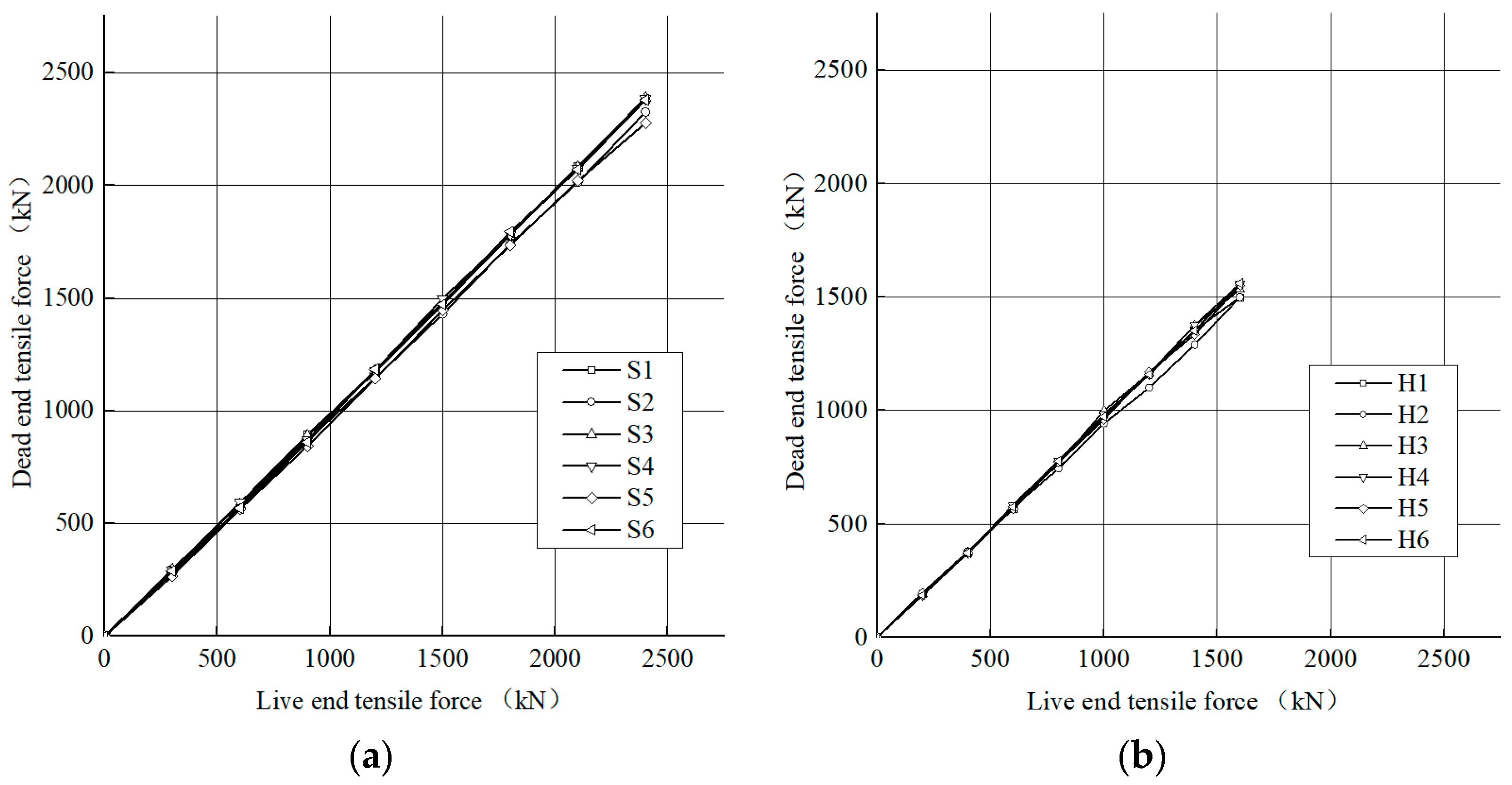
4.1. Stress Loss Due to Strand Harping

The harped strands were bent at the harping points, resulting in prestress loss due to the friction between the strands and the harping points. In order to assess the stress loss due to strand harping, one-end stressing tests of strands were conducted on the stressing bed for the box girder before concrete casting. As shown in Figure 7, six straight strands (S1 through S6) and six harped strands (H1 through H6) were selected for the test, and a hollow cylinder was used to stress the strands. The end next to the cylinder is regarded as the live end while the other end using a chuck is the dead end. Load cells were installed at both ends to record the stressing force.
The strand stressing process was conducted in eight steps. The straight strands were tensioned to 68% of the nominal ultimate strength, while the harped strands were tensioned to 61%. As shown in Figure 8, the dead end tensile force was linearly increased with the tensile force at the live end. The live end tensile forces of the straight and harped strands were 2% and 7% larger than the corresponding dead end tensile forces, respectively. Different from the test using one-end stressing technology, two-end strand stressing was conducted during the production of the prestressed concrete box girder. Thus, the tensile stress loss could reduce by half, which was 3.5% of the tensile force at the live end.
The friction effect at the harping points is shown in Figure 9. Based on the measured values of the strand stressing force, the friction factor μ of the harping points may be calculated using Equation (4). In this project, the harping angle was 8°. Accordingly, the friction factor μ could be taken as 0.251.
μ = 0.5 f L f D f L · sin θ
where:
  • f L = live end force (kN);
  • f D = dead end force (kN);
  • θ = harping angle of strand (degree).

4.2. Prestress Losses at Different Stages

(1)
Prestress Loss due to elastic shortening
In AASHTO LRFD 2017 5.9.3, prestress losses in pretensioned members are divided into loss due to elastic shortening and time-dependent losses. The prestress loss due to elastic shortening f E S can be calculated using Equation (5) directly if the value of f c g p cris known. In this project, a strain gauge was embedded at the center of gravity of prestressing (cgp) strands, and it indicated that f c g p reached 15.67 MPa after the detension of prestressing strands. However, in most cases, f c g p generally requires iteration. To avoid iteration, AASHTO LRFD 2017 also presents an alternative equation: Equation (C5.9.3.2.3a-1) as shown in Equation (6).
Δ f ES = E p E ci f cgp
Δ f ES = A ps f pi I g + e m 2 A g e m M g A g A ps I g + e m 2 A g + A g I g E ci E p
where:
  • fcgp = concrete stress at cgp (MPa).
  • Ep = modulus of elasticity of strand (MPa);
  • Eci = modulus of elasticity of concrete at detension (MPa);
  • A ps = gross area of strands (mm2);
  • A g = gross area of girder section (mm2);
  • e m = average strands eccentricity at midspan (mm);
  • f pi = the stress in strands immediately prior to transfer (MPa);
  • I g = moment of inertia of the gross girder section (mm4);
  • M g = midspan moment due to self-weight (N·mm).
In fact, the prestress loss due to elastic shortening may be calculated based on the measured longitudinal shortening value. The prestress loss due to elastic shortening may be estimated using Equation (7).
Δ f ES = E p Δ L L
where:
  • ΔL = longitudinal shortening of the girder (m);
  • L = length of the box girder (m).
In this project, strand detension was conducted at 6 d since the completion of concrete pouring. Displacement transducers were placed at both ends of the box girder, indicating that the average shortening of the girder was 14 mm. By using Equations (5)–(7), the prestress losses due to elastic shortening were 85.6, 80.2, and 83.7 MPa, respectively. Among the three calculated values, the measured prestress loss with the strain gauge at cgp of the midspan was the maximum, while the value based on the measured girder shortening was the median, and the differences between the maximum/minimum and the median were within 4%. This verified the reliability of the estimation of prestress loss due to elastic shortening.
(2)
Time-dependent Prestress Losses
In order to measure the time-dependent prestress losses due to shrinkage and creep of concrete, vibrating-wire strain gauges were used to measure concrete strain at the L/2 and L/4 sections within 28 days after detension, as shown in Figure 10. The strains due to elastic shortening were excluded. As shown in Figure 11, three strain gauges were symmetrically embedded in the top flange, two in the web, and three in the bottom flange at each section. The distribution of strains was approximately linear. The concrete strain at cgp could be interpolated based on the measured concrete strains. As shown in Figure 11, the concrete strains at cgp were 250 and 237 με at the L/2 and L/4 sections, respectively. Therefore, the average concrete strain at cgp could be taken as 243 με, which was used for the calculation of time-dependent prestress losses. Additionally, the curvature could be calculated which was the slope of the strain distribution along the depth of the girder. Accordingly, the curvatures were 52.6 ×   10 6 and 51.9 ×   10 6   ·   m 1 at the L/2 and L/4 sections, respectively. The measured strains and prestress losses are shown in Table 3. Within the three days after detension, the prestress losses increased rapidly, reaching 45% of prestress losses at 28 d. It reveals the effect of concrete shrinkage and creep in the early days.
In addition, AASHTO LRFD 2017 5.9.3 offers two approaches for predicting time-dependent prestress losses: approximate method and refined method. The approximate estimation of time-dependent prestress loss Δ f T D may be calculated using Equation (8). In this project, the average annual ambient relative humidity was taken as 76% based on the meteorological data, and the predicted time-dependent prestress losses using the approximate method were 85.9 MPa.
Δ f TD = ( 10 A ps f pi A g + 83 ) γ h γ st + Δ f R
where:
  • γ h = correction factor for relative humidity;
  • γ st = correction factor for specified concrete strength at time of prestress transfer to the concrete member;
  • f R = loss due to relaxation taken as 16.5 MPa herein.
As for the refined method addressed in AASHTO LRFD 2017 5.9.3.4, the effects of shrinkage, creep, and relaxation on prestress losses are, respectively, predicted. The time-dependent prestress losses are the sum of these three losses, as shown in Equation (9).
Δ f TD = Δ f SR + Δ f CR + Δ f R
where:
  • f SR = prestress loss due to shrinkage of concrete (MPa);
  • f CR = prestress loss due to creep of concrete (MPa).
The time-dependent prestress losses were predicted with the refined method over one year after detension. The predicted prestress losses were 69.2 MPa at 28 d, 87.8 MPa at 56 d, and 112.8 MPa at 364 d. In comparison with the measured prestress losses of 47.4 MPa at 28 d, the corresponding predicted values using the refined method were larger by 37%. Additionally, the time-dependent prestress losses due to creep and shrinkage were predicted with the approximate method and the value was 85.9 MPa. This value was close to the losses of 87.8 MPa at 56 d and was 76% of the losses of 112.8 MPa at 364 d predicated with the refined method.
(3)
Total prestress losses
The total prestress losses comprise both the instantaneous prestress losses due to elastic shortening and the time-dependent prestress losses due to concrete shrinkage, creep, and strand relaxation. As shown in Figure 12, the development of measured prestress losses and predicted prestress losses over time were compared. At 28 d after detension, the measured total prestress losses were 133.0 MPa while the predicted total losses using the refined method were 149.4 MPa, indicating the prediction overestimated the prestress losses by 12%. The predicted prestress losses using the approximate method were close to the value at 56 d using the refined method, and the total losses at 56 d were 168.0 MPa. The effect of concrete shrinkage and creep were generally more significant in the early days; thus, the increasing rate of prestress losses declines over time. This trend is revealed by the curve of the accumulated losses predicted with the refined method in Figure 12. With the refined method, the total prestress losses at 28 d and at 56 d reached 77% and 87% of the prestress losses of 193.0 MPa at 364 d, respectively. It indicated that the prestress losses of the box girder developed rapidly in the first two months, accounting for the majority.

5. Conclusions and Discussion

The transfer length and prestress losses of a 32.6 m long prestressed concrete box girder with 18 mm straight strands were studied in this research. Based on the experiment tests and the calculation, the following conclusions were drawn.
Different equations were used to predict the transfer length of 18 mm strands, and the predicted values varied widely. The average measured transfer length of 18 mm strands was approximately 700 mm, which was significantly smaller than the transfer length predicted by AASHTO LRFD 2017 and ACI 318-19. Among the existing equations, Mitchell’s equation suggested a rational transfer length which was the closest to the measured values.
The instantaneous prestress loss of the box girder due to elastic shortening calculated with AASHTO LRFD 2017 alternative equation Eq. (C5.9.3.2.3a-1) was close to the actual loss, which was directly measured from the concrete strain at the center of gravity of prestressing strands or was analyzed based on the measured longitudinal shortening of the girder. Of the three calculations, the value suggested by the AASHTO LRFD 2017 alternative equation Eq. (C5.9.3.2.3a-1) was the minimum.
The time-dependent prestress losses were monitored with the embedded concrete strain gauges at two sections within 28 days after strand detension. The measured total prestress losses at 28 d were 133.0 MPa, while the refined method in AASHTO LRFD 2017 overestimated the losses by 12%. In spite of the discrepancies between the prediction and the measurement, the predictions with the AASHTO LRFD 2017 methods are still meaningful. The total prestress losses at 56 d predicted with the refined method were 168.0 MPa, which were 87% of the total losses of 193.0 MPa at 364 d and were close to the losses predicted with the approximate method. This indicated that the prestress losses which accumulated in the first two months accounted for the majority of the total losses in the long term.

Author Contributions

Conceptualization, X.J., H.C., Y.Z., L.M., J.D., W.Z. and Y.L.; methodology, X.J. and H.C.; software, H.C. and W.Z.; investigation, X.J. and H.C.; resources, X.J., H.C., Y.Z., J.D., W.Z. and Y.L.; writing—original draft preparation, X.J. and H.C.; writing—review and editing: X.J., H.C. and W.Z.; All authors have read and agreed to the published version of the manuscript.

Funding

The research was sponsored by the foundation of Key Laboratory of Transport Industry of Bridge Detection Reinforcement Technology (Chang’an University) (300102219526); Department of Science and Technology of Hubei Province (2022CFB256); Ezhou Science and Technology Bureau (EZ01-005-2022025); Graduate Innovative Fund of Wuhan Institute of Technology (CX2022181); Science Foundation Research Project of Wuhan Institute of Technology (K2021035).

Data Availability Statement

Not applicable.

Conflicts of Interest

The authors declare no conflict of interest.

Nomenclature

A g gross area of girder sectionLlength of the box girder
A ps gross area of strandsLttransfer length of strands
Cdistance from concrete surface to closest center of strand M g midspan moment due to self-weight
d b diameter of the strand σ pi stress of prestressing strands after detension
e m average strands eccentricity at midspan α p 1 1.0 for gradual release and 1.25 for sudden release
Epmodulus of elasticity of strand α p 2 0.5 for verifying the transverse stress due to prestress transfer in the anchorage zone
Ecimodulus of elasticity of concrete at detension α p 3 0.5 for strands
f bpd design bond strength μ the friction factor
f ci concrete compressive strength at detension θ harping angle of strand
fcgpconcrete stress at cgp γ h correction factor for relative humidity
f D dead end force γ st correction factor for specified concrete strength at time of prestress transfer to the concrete member
f L live end force f ES loss due to elastic shortening
f pi the stress in strands immediately prior to transfer Δ f TD time-dependent prestress losses
f se the effective stress in prestressing strands after losses f R loss due to relaxation
f si effective stress in prestressed strand at detension f SR prestress loss due to shrinkage of concrete
I g moment of inertia of the gross girder section f CR prestress loss due to creep of concrete
l bp basic anchorage length

References

  1. Schualer, G. Producer’s experience with 10,000 psi concrete and 0.7-in. diameter strands. HPC Bridge Views, 1 March 2009; Issue 54. [Google Scholar]
  2. Ma, Z.J.; Burdette, E.G. Transfer Length and Girder-End Confinement of AASHTO-PCI BT Girders with Larger Capacity Prestressing Strands; Technical Report: RES-2010-23; The University of Tennessee Knoxville: Knoxville, TN, USA, 2011. [Google Scholar]
  3. Salazar, J.; Yousepour, H.; Katz, A.; Abyaneh, R.A.; Kim, H.; Garber, D.; Hrynyk, T.; Bayrak, O. Benefits of using 0.7 in. (18 mm) diameter strands in precast, pretensioned girders: A parametric investigation. PCI J. 2017, 62, 59–75. [Google Scholar] [CrossRef]
  4. AASHTO. AASHTO LRFD Bridge Design Specifications, 8th ed.; American Association of State Highway and Transportation Officials: Washington, DC, USA, 2017. [Google Scholar]
  5. Jiang, X.; Ban, X.L.; Ma, L.; Su, Y.H.; Cao, Q.; Zhang, Z.Y.; Guo, J.C. Prestressed concrete box girder with high-capacity strands-monitoring and analysis during fabrication. Buildings 2022, 12, 911. [Google Scholar] [CrossRef]
  6. Russell, B.W.; Burns, N.H. Measured transfer lengths of 0.5 and 0.6 in. strands in pretensioned concrete. PCI J. 1996, 49, 44–65. [Google Scholar] [CrossRef]
  7. Song, W.C.; Ma, Z.J.; Vadivelu, J. Transfer length and splitting force calculation for pretensioned concrete girders with high-capacity strands. J. Bridge Eng. 2014, 19, 04014026. [Google Scholar] [CrossRef]
  8. Jin, K.K.; Jun, M.Y.; Hong, J.Y. Experimental evaluation of transfer length in pretensioned concrete beams using 2400-MPa prestressed strands. J. Struct. Eng. 2016, 142, 04020186. [Google Scholar]
  9. Dang, C.N.; Floyd, R.W.; Hale, W.M.; Martí-Vargas, J.R. Measured development lengths of 0.7 in. (17.8 mm) strands for pretensioned beams. ACI Struct. J. 2016, 113, 525–535. [Google Scholar] [CrossRef]
  10. Dang, C.N.; Hale, W.M.; Martí-Vargas, J.R. Quantification of bond performance of 18-mm prestressing steel. Constr. Build. Mater. 2018, 159, 451–462. [Google Scholar] [CrossRef]
  11. Dang, C.N.; Martí-Vargas, J.R.; Hale, W.M. Bond mechanism of 18-mm prestressing strands: New insights and design applications. Struct. Eng. Mech. 2020, 76, 67–81. [Google Scholar]
  12. Jiang, X.; Cabage, J.; Jing, Y.; John, Z.; Burdette, E.G. Effect of embedment length on bond of 18 mm (0.7 in.) strand by pullout test. ACI Struct. J. 2017, 114, 707–717. [Google Scholar] [CrossRef]
  13. Jiang, X.; Gui, Q.; Ma, Z.J. Pretensioned pullout test of 18mm (0.7 in.) diameter strand with different embedment lengths. Struct. Concr. 2019, 20, 1842–1857. [Google Scholar] [CrossRef]
  14. Jiang, X.; Ma, Z.J. Prestress losses for AASHTO type I girder with larger capacity strands. In Proceedings of the PCI Convention and National Bridge Conference, Texas, TX, USA, 21–24 September 2013. [Google Scholar]
  15. Garber, D.B.; Gallardo, J.M.; Deschenes, D.J.; Bayrak, O. Prestress loss calculations: Another perspective. PCI J. 2016, 61, 68–85. [Google Scholar] [CrossRef]
  16. Mohebbi, A.; Graybeal, B. Prestress loss model for ultra-high performance concrete. Eng. Struct. 2022, 252, 113645. [Google Scholar] [CrossRef]
  17. Almohammedi, A.; Murray, C.D.; DANG, C.N.; Hale, W.M. Investigation of measured prestress losses compared with design prestress losses in AASHTO Types II, II, IV, and VI bridge girders. PCI J. 2021, 66, 32–48. [Google Scholar] [CrossRef]
  18. Thedy, J.; Liao, K.W.; Tseng, C.C.; Liu, C.M. Bridge health monitoring via displacement reconstruction-based NB-IoT technology. Appl. Sci. 2020, 10, 8878. [Google Scholar] [CrossRef]
  19. Bonopera, M.; Chang, K.C. Novel method for identifying residual prestress force in simply supported concrete girder-bridges. Adv. Struct. Eng. 2021, 24, 3238–3251. [Google Scholar] [CrossRef]
  20. Bagge, N.; Nilimaa, J.; Blanksvärd, T.; Elfgren, L. Instrumentation and full-scale test of a post-tensioned concrete bridge. Nord. Concr. Res. 2014, 51, 63–83. [Google Scholar]
  21. Bagge, N.; Nilimaa, J.; Elfgren, L. In-situ methods to determine residual prestress forces in concrete bridges. Eng. Struct. 2017, 135, 41–52. [Google Scholar] [CrossRef]
  22. GB/T 50081-2002; Standard for Test Method of Mechanical Properties on Ordinary Concrete. China Architecture Publishing & Media Co., Ltd.: Beijing, China, 2002.
  23. American Concrete Institute (ACI) Committee 318. Building Code Requirements for Structural Concrete (ACI 318-19) and Commentary; ACI: Farmington Hills, MI, USA, 2019. [Google Scholar]
  24. Comité Euro-International Du Beton and the Federation Internationale de la Précontrainte (CEB-FIP). Model Code 2010; CEB-FIP: Lausanne, Switzerland, 2010. [Google Scholar]
  25. Martin, L.D.; Scott, N.L. Development of prestress strand in Pretensioned Members. ACI J. 1976, 73, 453–456. [Google Scholar]
  26. Zia, P.; Mostafa, T. Development Length of Prestressing Strands. PCI J. 1977, 22, 54–65. [Google Scholar]
  27. Mitchell, D.; Cook, W.D.; Khan, A.A.; Tham, T. Influence of high strength concrete on transfer and development length of pretensioning strand. PCI J. 1993, 38, 52–66. [Google Scholar] [CrossRef]
  28. Deatherage, J.H.; Burdette, E.G.; Chew, C.K. Development length and lateral spacing requirements of prestressing strand for prestressed concrete bridge girders. PCI J. 1994, 39, 70–83. [Google Scholar] [CrossRef]
  29. Oh, B.H.; Lim, S.N.; Lee, M.K.; Yoo, S.W. Analysis and prediction of transfer length in pretensioned, prestressed concrete members. ACI Struct. J. 2012, 111, 549–559. [Google Scholar] [CrossRef]
Figure 1. Beam-end section dimensions (units: cm).
Buildings 13 01939 g001
Figure 2. Midspan section dimensions (units: cm).
Buildings 13 01939 g002
Figure 3. Concrete beam specimens. (a) Concrete casting. (b) Strand stressing.
Buildings 13 01939 g003
Figure 4. Distribution of strain gauges in beam end (units: mm).
Buildings 13 01939 g004
Figure 5. Measured transfer length of 18 mm strands.
Buildings 13 01939 g005
Figure 6. Transfer length of 18 mm strands [4,6,23,24,25,26,27,28,29].
Buildings 13 01939 g006
Figure 7. One-end stressing test (units: cm).
Buildings 13 01939 g007
Figure 8. Tensile forces at the live end and dead end. (a) Straight strand. (b) Harped strand.
Buildings 13 01939 g008
Figure 9. Tensile force loss due to friction at harping points.
Buildings 13 01939 g009
Figure 10. Layout of concrete strain gauges embedded in the box girder.
Buildings 13 01939 g010
Figure 11. Measurement of prestress losses based on concrete strains (units: cm).
Buildings 13 01939 g011
Figure 12. Accumulation of total prestress losses over time after detension.
Buildings 13 01939 g012
Table 1. Mechanical properties of concrete.
Time (d)361428
Compressive Strength (MPa)32.050.156.462.0
Modulus of Elasticity (MPa)32,20035,70041,30043,000
Table 2. Transfer length calculation equations (unit: mm).
ResearcherEquation
Martin and Scott (1976) [25] L t = 80 d b
Zia and Mostafa (1977) [26] L t = 25.4 ( 1.5 f si f ci d b 4.6 )
Russell and Burns (1993) [6] L t = f si d b 13.8
Mitchell, Cook and Khan et al. (1993) [27] L t = 0.048 f si d b 20 f ci
Deatherage, Burdette and Chew et al. (1994) [28] L t = f si 20.7 d b
Oh, Lim and Lee et al. (2012) [29] L t = 8 f se ( 1 f ci ) 1 / 3 d b 1.28 ( 1 C 20   +   0.25 )
where: f ci = concrete compressive strength at detension (MPa); f si = effective stress in prestressed strand at detension (MPa); C = distance from concrete surface to closest center of strand (mm).
Table 3. Development of concrete strains and time-dependent prestress losses.
Days after Detension (d)Concrete Strain at cgp (με)Prestress Losses (MPa)
311021.5
613826.9
1418235.5
2824347.4
Disclaimer/Publisher’s Note: The statements, opinions and data contained in all publications are solely those of the individual author(s) and contributor(s) and not of MDPI and/or the editor(s). MDPI and/or the editor(s) disclaim responsibility for any injury to people or property resulting from any ideas, methods, instructions or products referred to in the content.

