
Study on the Impact of a Metro Depot Cover Structure on the Existing Metro Structure and Additional Settlement of Tracks

Abstract
:1. Introduction
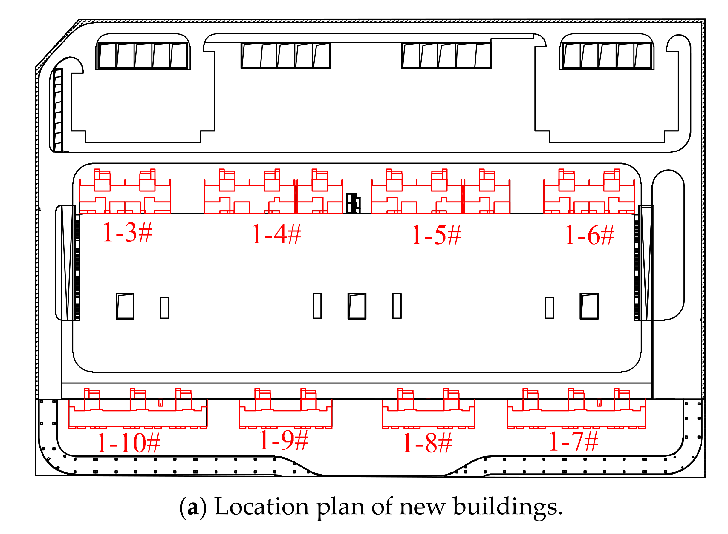
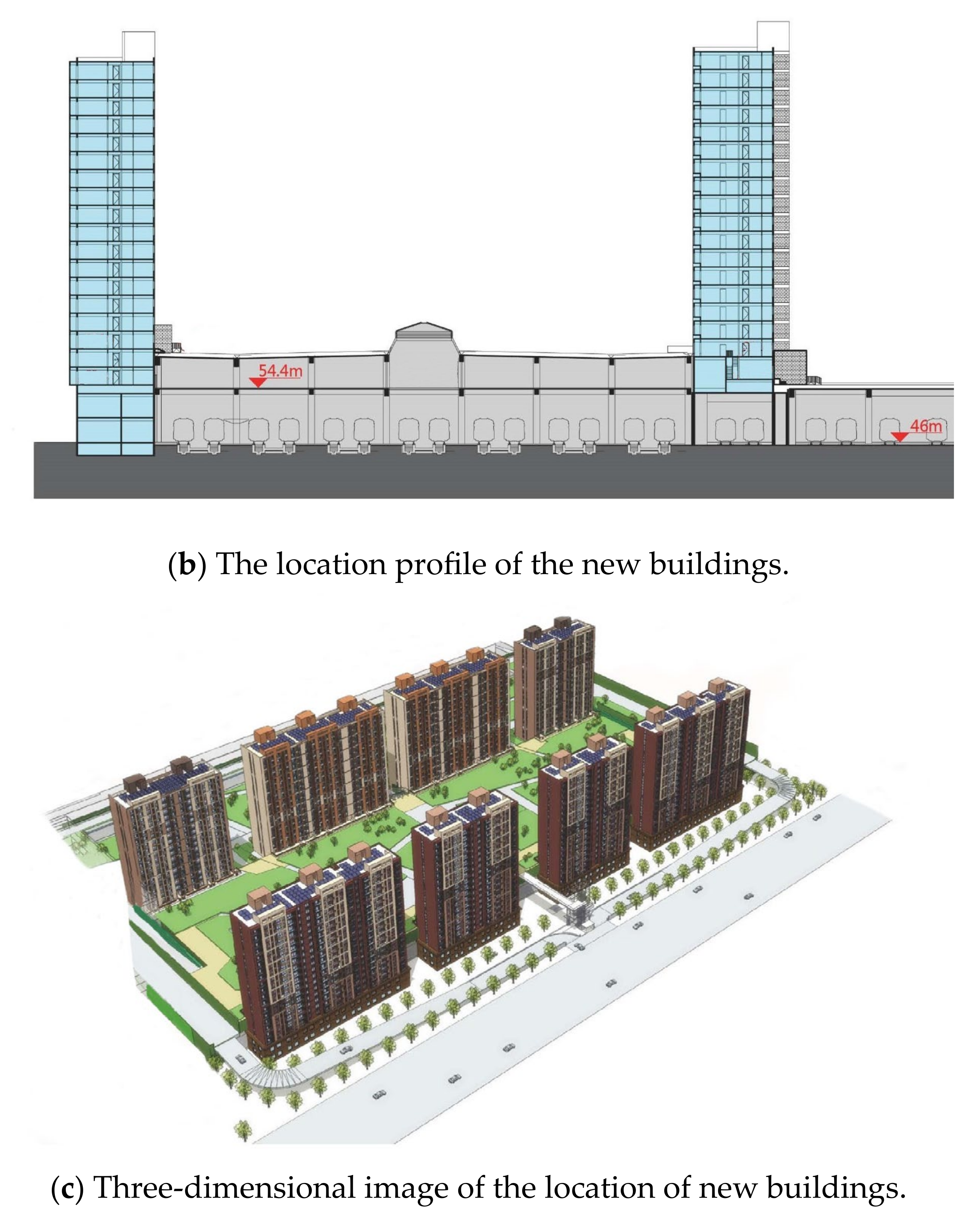
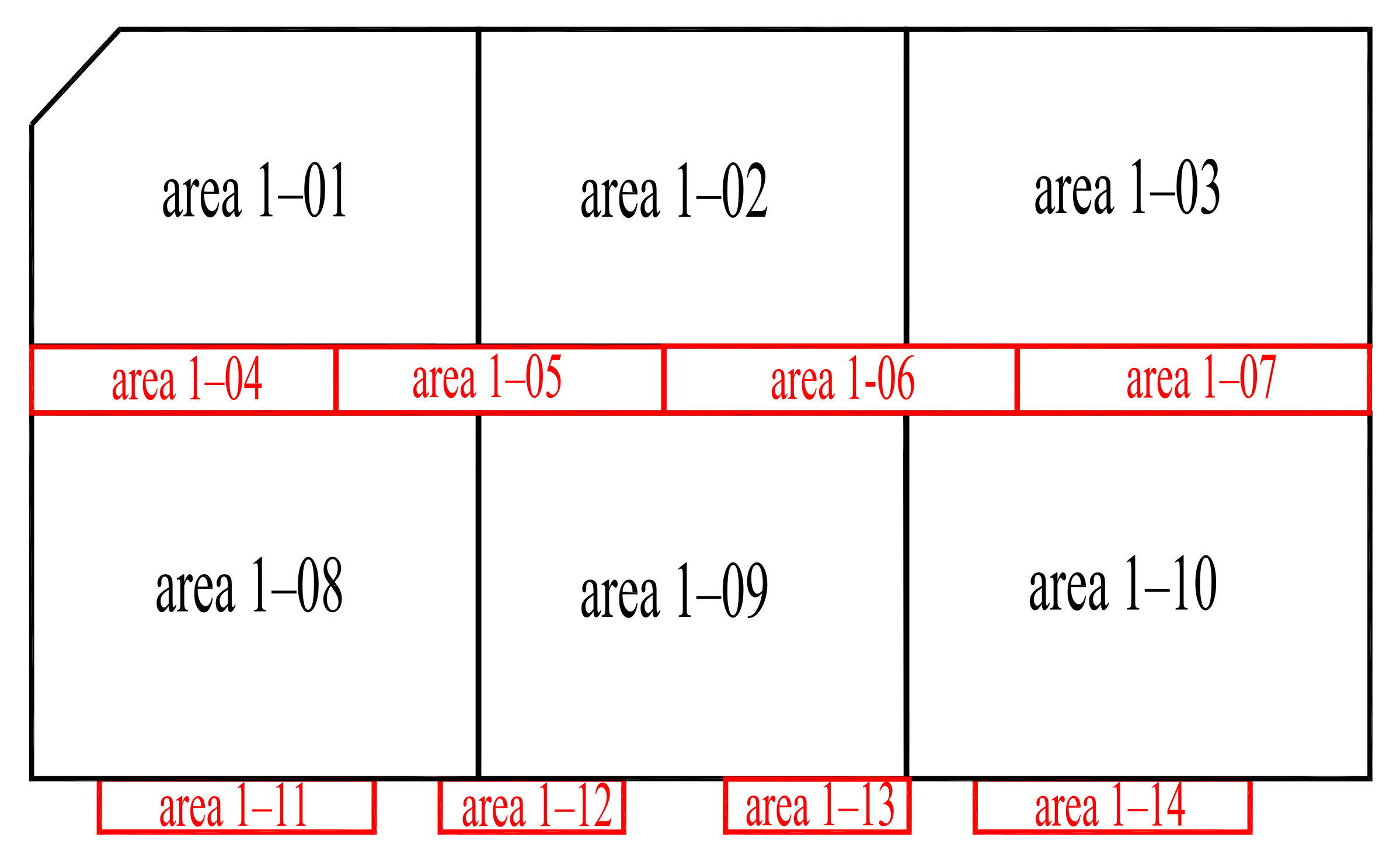
2. Project Overview
3. Analysis of the Settlement Mechanism of the Structural Pile’s Foundation and Track
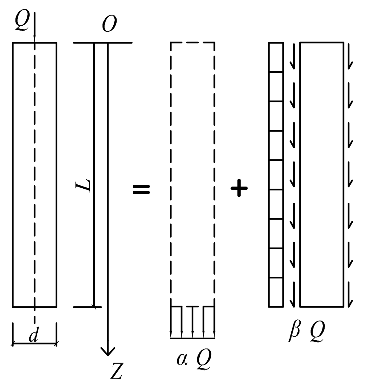
3.1. Settlement of Pile Foundation Due to Secondary Loading
3.2. The Effect of Pile Settlement on Track Structure
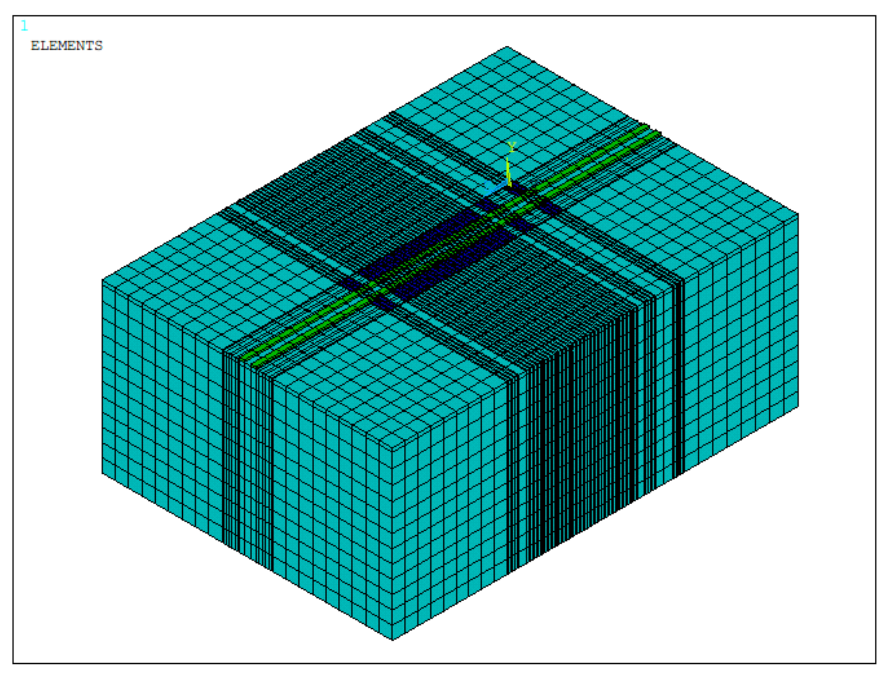
4. Numerical Simulation Analysis
4.1. Soil Material Parameters
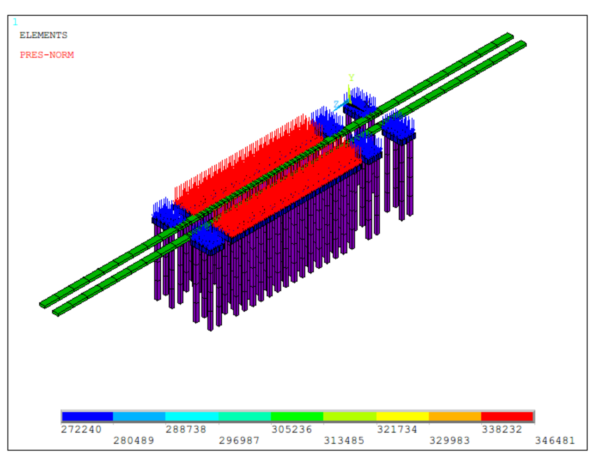
4.2. Model Loads
- 1.
- Roof load

| Serial No. | Name | Maximum Structural Design Live Load kN/m2 |
|---|---|---|
| 1 | Fire Lane | 35 |
| 2 | Upholstered roofs (metro depot roof) | 3.0 |
| 3 | Upholstered roofs (parking garage roofs) | 4.0 |
| 4 | No upper roof | 0.5 |
- 2.
- New building loads:
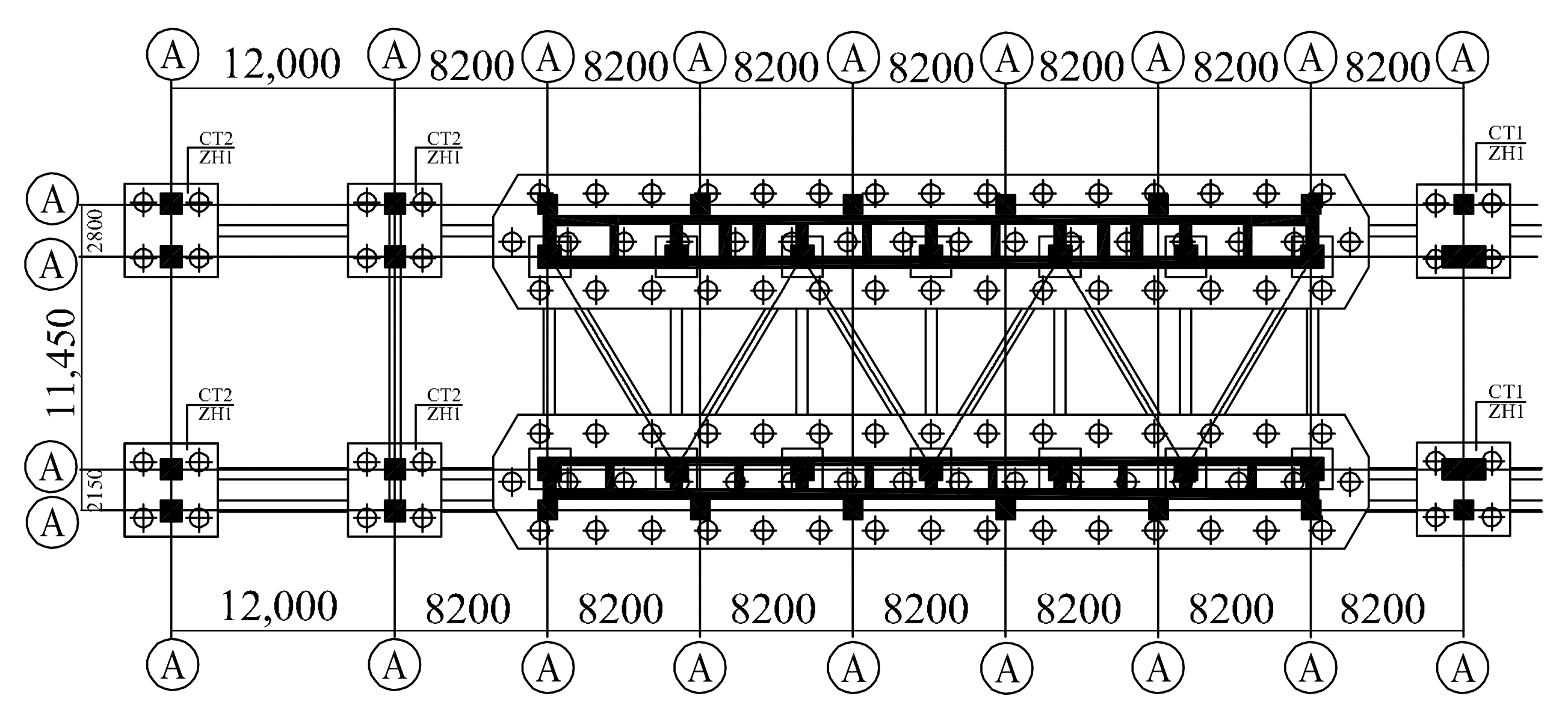
4.3. Model Building
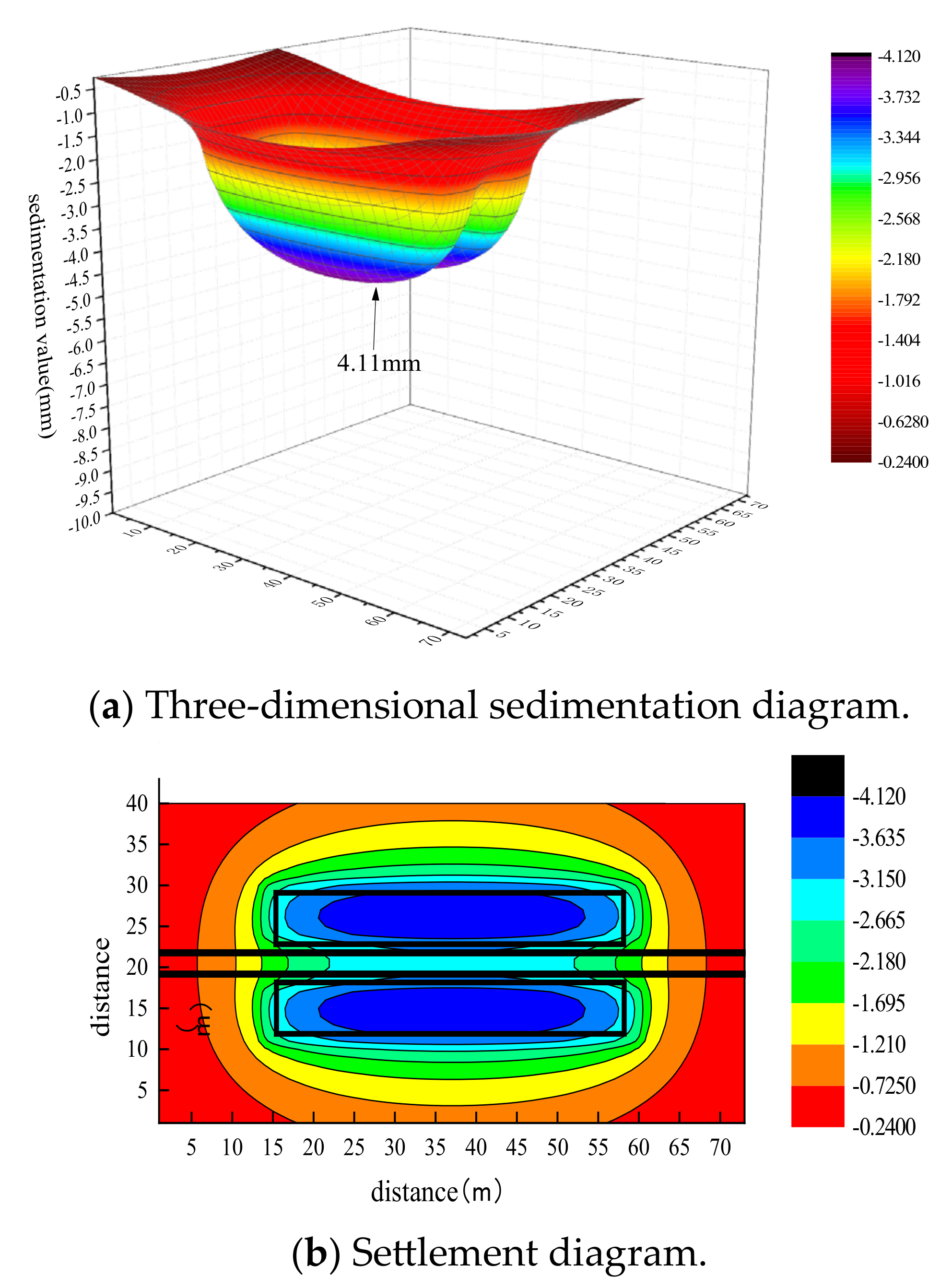
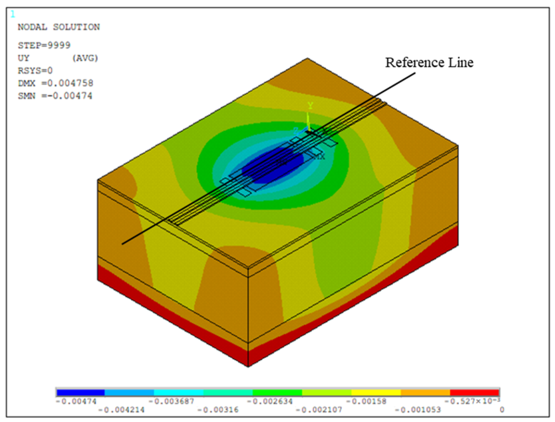
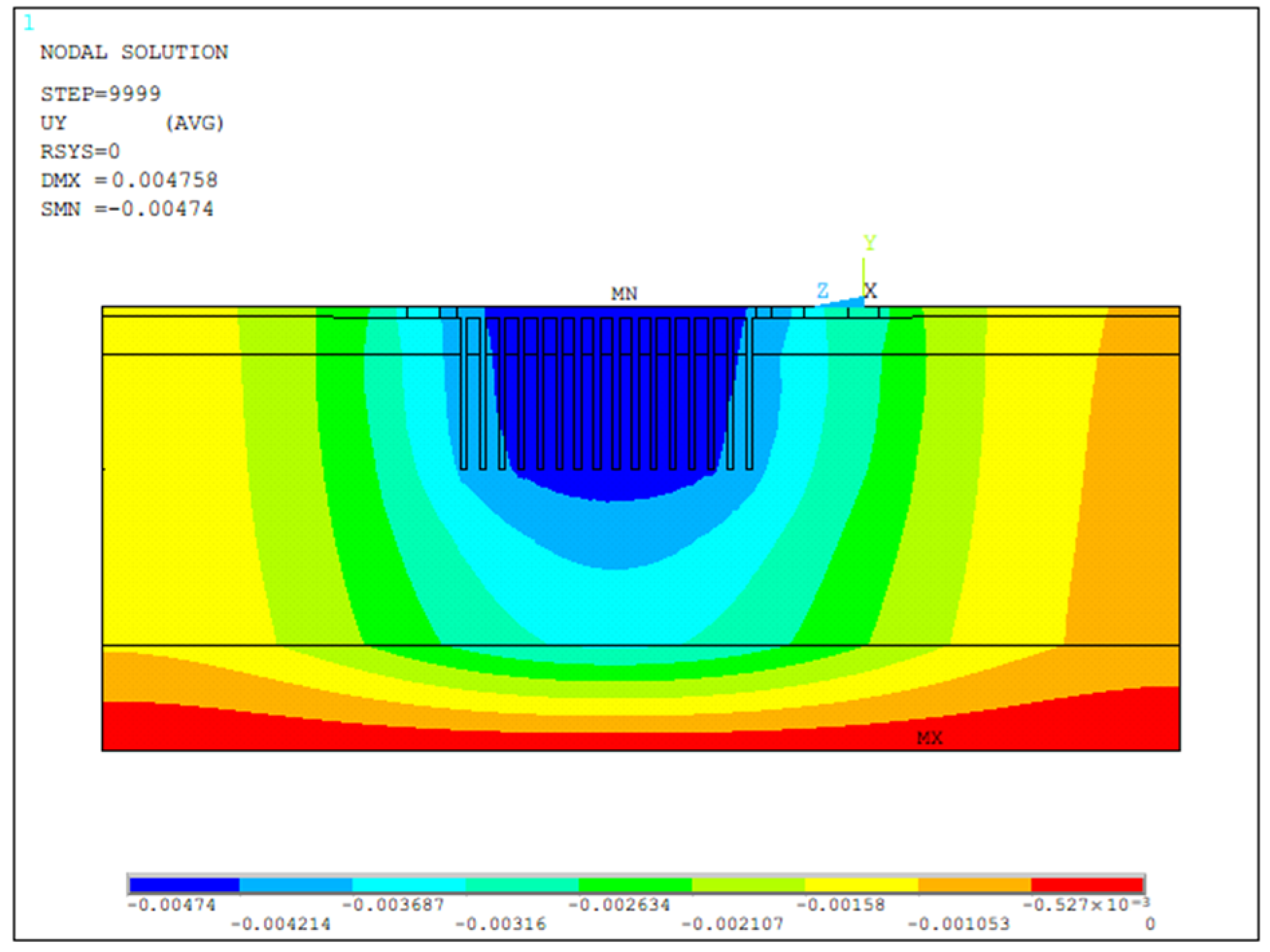
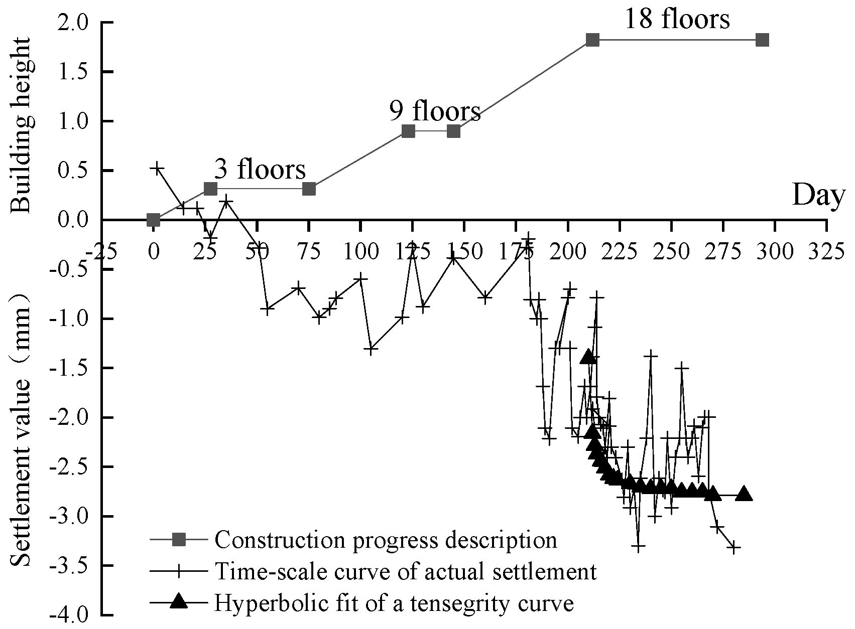
4.4. Analysis of the Model Calculation Results
5. Comparative Analysis of the Monitoring Data
5.1. Foundation Settlement Analysis
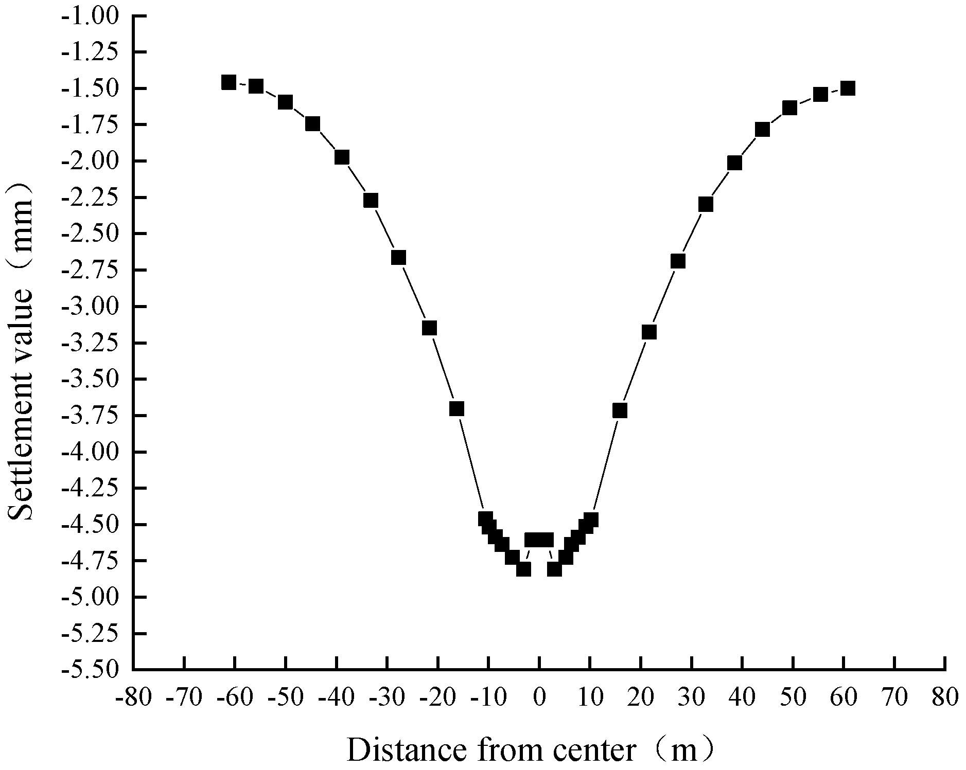
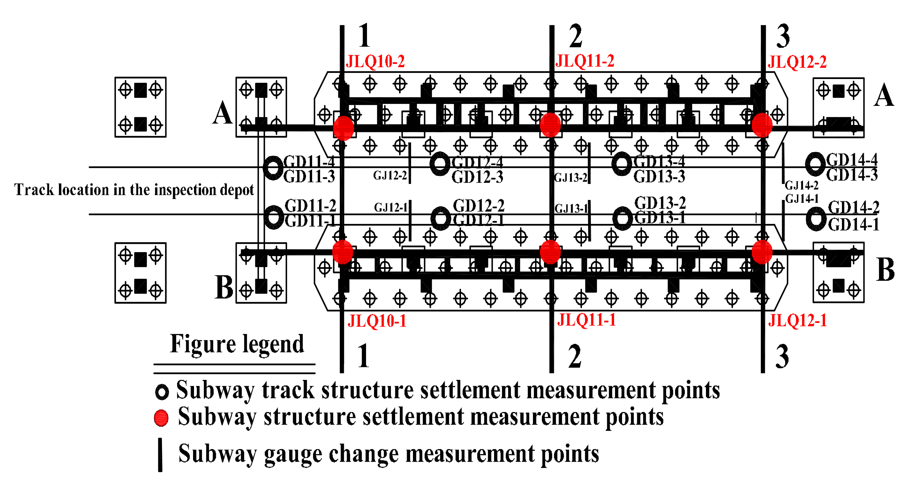
5.2. Analysis of Vertical Deformation of the Track Structure
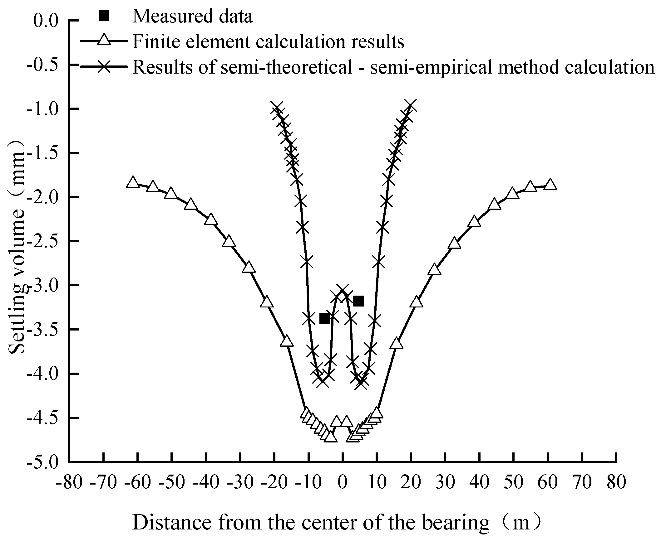
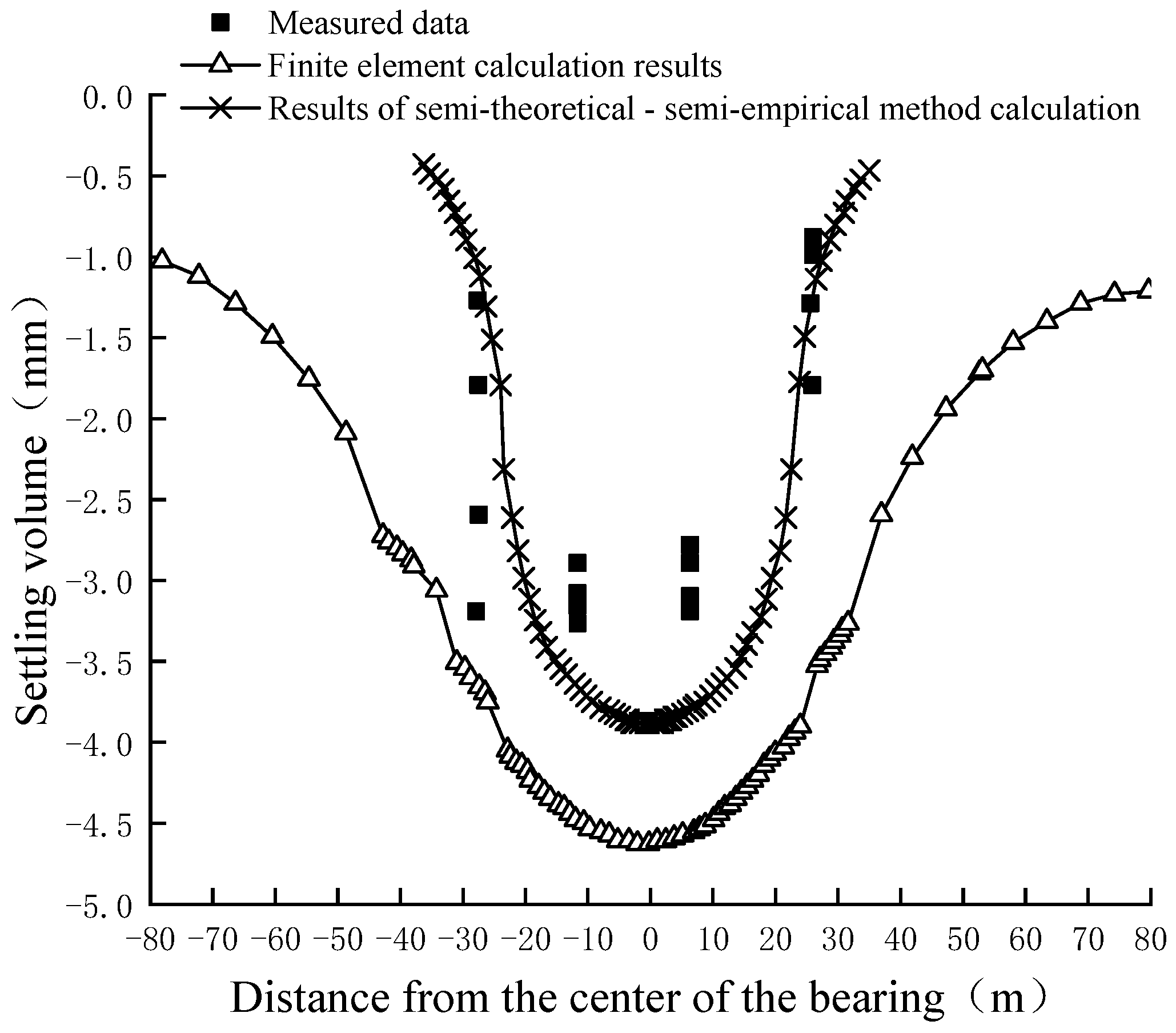
5.3. Comparison Analysis of the Monitoring Data and the Calculation Results
6. Case Studies of Similar Projects
7. Conclusions and Recommendations
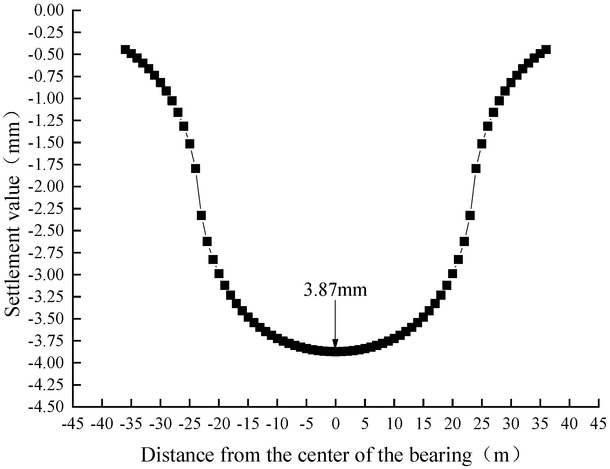
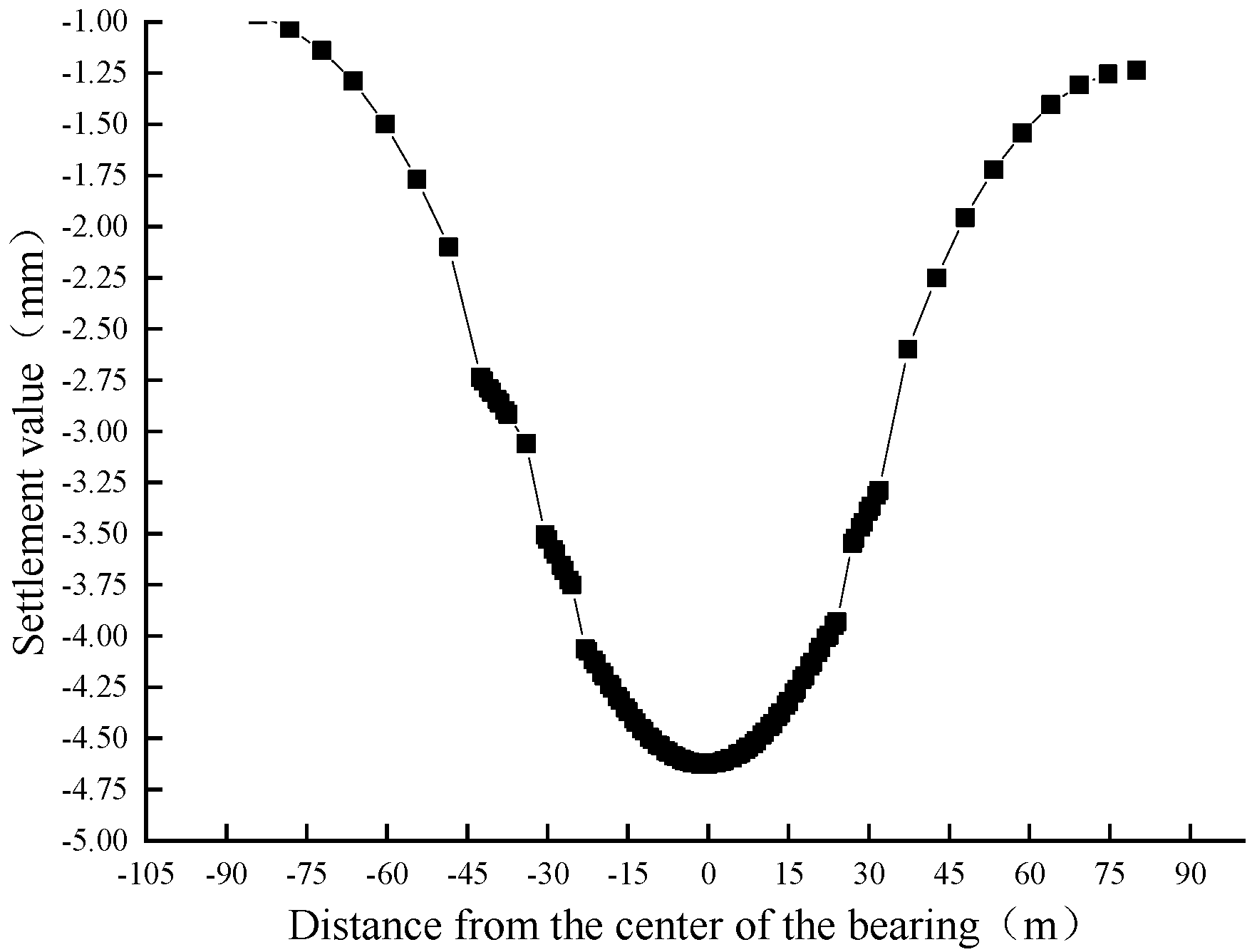
- This paper is based on the calculation method of the friction end bearing pile Mindlin solution and the pile foundation force assumptions to calculate the use of the library pile foundation in the secondary load loading under the action of settlement and to calculate the impact on the track structure. The finite element analysis software is used to establish the model method for the superstructure construction for comparison and verification, and the influence of the loading of the upper construction on the settlement of the use depot is investigated. The theoretical calculations show the maximum track settlement of 3.87 mm, and the numerical calculation results show a maximum settlement of 4.63 mm.
- The comparison with the monitoring data shows that the method is feasible for the settlement analysis of friction end-bearing piles with secondary loading. In the single pebble ground conditions of this project, the calculation assumptions are more consistent with the actual pile stresses. In the area with more complex ground conditions, the unevenness of the distribution and the lateral wear resistance will be greater.
- Within the influence of the pile foundation settlement, there will be some additional influence on the surrounding rail tracks, with the maximum settlement occurring at the center of the bearing platform and gradually decreasing outward. According to the calculation analysis, the settlement change rate is the largest at 2.5 times the burial depth of the pile foundation from the center of the bearing, and the surface settlement decreases abruptly beyond 2.5 times the burial depth.
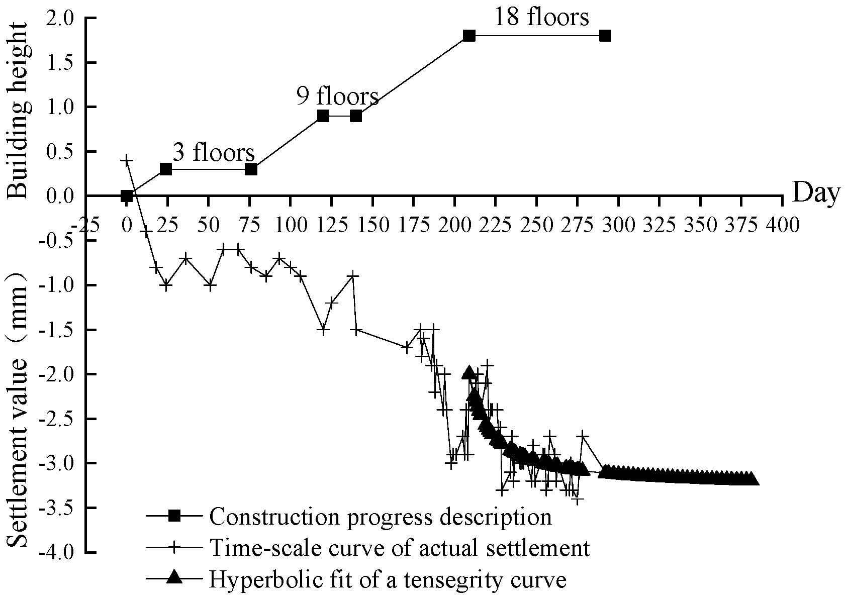
- The construction of the superstructure area should adopt the principle of laying in layers within the whole floor at the same time to avoid local bias load and uneven settlement to the detriment of the structure, which can effectively control the impact to the track.
- Through comparison with similar superstructure projects in Beijing, the superstructure project is able to control the impact on the structure within the required range under the conditions of information-based construction, uniform loading of the structure and control of the construction process. The overall risk of this type of project is manageable.
Author Contributions
Funding
Data Availability Statement
Conflicts of Interest
References
- Xue, B. Discussion on the comprehensive development mode of urban rail transit vehicle base. Shanxi Archit. 2009, 35, 40–41. [Google Scholar]
- Diaz, R.B. Impacts of Rail Transit on Property Values. APTA Rapid Transit Conf. Proc. Pap. 1999, 66–73. Available online: http://www.rtd-fastracks.com/media/uploads/nm/impacts_of_rail_transif_on_property_values.pdf (accessed on 10 June 2023).
- Kuzmyak, J.R.; Pratt, R.H.; Douglas, G.B.; Spielberg, F. Traveler Response to Transportation System Changes. Chapter 15-Land Use and Site Design; Transportation Research Board: Washington, DC, USA, 2003. [Google Scholar]
- Inman, R.P. Making Cities Work: Prospects and Policies for Urban America; Princeton University Press: Princeton, NJ, USA, 2009. [Google Scholar]
- Yuan, F. Research on integrated development mode of urban rail transit metro depot. Railw. Stand. Des. 2013, 1, 130–133. [Google Scholar]
- Yang, X.Y. Research on Architectural Planning and Construction Management of Metro Superstructures. Master’s Thesis, Tianjin University, Tianjin, China, 2013. [Google Scholar] [CrossRef]
- Ye, X.F. Comparative study of domestic and foreign urban rail transit metro depots. Urban Rail Transit Res. 2003, 6, 72–77. [Google Scholar]
- Jiang, K.W. Design of Building Structures on Metro Train Inspection Database. In Proceedings of the Fourth National Building Structure Technology Exchange Conference (Part I), Suzhou, China, 30 May 2013. 5af198cac095d71bc8c7c7a7. [Google Scholar]
- Hu, X.W.; Wang, J.; Chen, D. Structural design of D area of property above Tanglang Depot of Shenzhen Metro. In Proceedings of the Fourth National Building Structure Technology Exchange Conference, Suzhou, China, 30 May 2013. 5af19a9dc095d71bc8c7ffe8. [Google Scholar]
- Bao, L.J.; Huang, Y.Q.; Gao, S.X. Comparison and selection of structural system of a subway upper cover project. In Proceedings of the Fourth National Building Structure Technology Exchange Conference, Suzhou, China, 30 May 2013; Volume 4. CNKI:SUN:JCJG.0.2013-S1-024. [Google Scholar]
- Rhim, J. Relationship between Land Use Characteristics of Station Impact Area and Subway Ridership in Seoul; Springer: Berlin/Heidelberg, Germany, 1992. [Google Scholar]
- Shen, J.; Wang, J. Design of superstructure property development in Pingxifu metro depot of Beijing Metro Line 8. Mod. Urban Rail Transp. 2011, S1, 32–35. [Google Scholar]
- He, J. Architectural design concept and practice of Guangzhou rail transit Xajiao metro depot superstructure. Urban Express Transp. 2010, 6, 37–40. [Google Scholar]
- Xu, L. Structural design of the property above the Qianhai Bay metro hub in Shenzhen. Annex. Constr. Technol. 2010, 7, 37–40. [Google Scholar]
- Le, Q. Hangzhou metro seven fortress metro depot superstructure design related issues. Chongqing Archit. 2007, 4, 36–38. [Google Scholar]
- Yv, X.Z. Analysis and highlights of station track engineering in Shenzhen Metro superstructure property mode. China High-Tech Enterp. 2013, 2, 70–72. [Google Scholar]
- Lin, C.J.; Zhuang, Y.X.; Qi, Y.K. Research on the development of metro and superstructure properties in Hong Kong and its inspiration for the development and construction of superstructure properties in Shenzhen. Technol. Ind. 2011, 11, 143–146. [Google Scholar]
- Chen, Y.F. Difficult design of water supply and drainage for property above the metro depot of Henggang metro in Shenzhen. Urban Constr. Theory Res. 2011, 31, 1–3. [Google Scholar]
- Wang, Q.Q. A brief discussion on commercial complexes of metro superstructure properties. Urban Constr. Theory Res. 2013, 13, 615. [Google Scholar]
- Kou, Z.Y. A brief discussion on the architectural design of metro superstructure properties. Urban Constr. Theory Res. 2013, 24, 1–6. [Google Scholar]
- Atkinson-Palombo, C.; Kuby, M.J. The geography of advance transit-oriented development in metropolitan Pheonix. J. Transp. Geogr. 2010, 21, 2000–2007. [Google Scholar]
- Young, J.M. Tax on Land and Buildings; IMF Publication Service: Washington, DC, USA, 1996; pp. 263–265. [Google Scholar]
- Wang, S. Research on Settlement Characteristics of Long and Short Pile Composite Foundation under Fill Roadbed. Master’s Thesis, Zhengzhou University, Zhengzhou, China, 2010. [Google Scholar] [CrossRef]
- Ministry of Housing and Urban-Rural Development of the People’s Republic of China. Technical Code for Pile Foundation of Buildings. Geotechnics 2008, 11, 3020. [Google Scholar]
- Gu, Z.F.; Liu, Y.S.; Liu, S.S. Discussion of the Asaoka method to calculate the settlement deviation of soft foundation by repairing the stop method. Geotechnics 2010, 31, 2238–2240. [Google Scholar]
- Mindlin, R.D. Force at a point in the interior of a seminfinite solid. Physics 1936, 7, 195–202. [Google Scholar] [CrossRef]
- Geddes, J.D. Stresses in foundation soils due to vertical subsurface load. G60 Tech. 1966, 16, 1–255. [Google Scholar]
- Poulos, H.G.; Davis, E.H. The settlement behaviour of single axially loaded incompressible piles and piles. G60 Tech. 1969, 18, 351–371. [Google Scholar] [CrossRef]


| Bearing Capacity of Pile Foundation | Phase I Load (kN) | Phase II Load (kN) | Single Pile Bearing Capacity Characteristic Value (kN) |
|---|---|---|---|
| Upper cover area | 490 | 3447 | 5208 |
| Name | Thickness (m) | Density (g/cm3) | Poisson’s Ratio | Cohesion (kPa) | Internal Friction Angle (°) | Elastic Modulus (MPa) |
|---|---|---|---|---|---|---|
| Clayey powdered soil plain fill | 0.9 | 1.85 | 0.3 | -- | -- | 19.3 |
| Powdery clay | 6.4 | 1.92 | 0.2 | 26.0 | 19.1 | 18.0 |
| Nakasand | 4.8 | 2.00 | 0.2 | 0 | 32 | 80.0 |
| Pebbles | 30 | 2.20 | 0.3 | 0 | 40 | 200.0 |
| Project Title | Conditions of the Superstructure | Stratigraphy and Foundation Preliminaries | Final Settlement (mm) |
|---|---|---|---|
| Beijing Metro Line 6 Wuluju metro depot superstructure | 9 buildings above, 6 and 10 stories | Pebble strata, end bearing piles, and pile length of 13.5 m | 3.2 mm |
| Beijing Metro Line 6 Pingxifu vehicle superstructure | 9 buildings above, 22 and 11 stories | Clay strata, friction pile, and pile length of 60 m | 6.5 mm |
| Beijing Metro Line 16 Beianhe metro depot superstructure | 23 buildings above, 6 and 9 stories | Clay, rounded gravel stratum, friction pile, and pile length of 34 m | 3.4 mm |
Disclaimer/Publisher’s Note: The statements, opinions and data contained in all publications are solely those of the individual author(s) and contributor(s) and not of MDPI and/or the editor(s). MDPI and/or the editor(s) disclaim responsibility for any injury to people or property resulting from any ideas, methods, instructions or products referred to in the content. |
© 2023 by the authors. Licensee MDPI, Basel, Switzerland. This article is an open access article distributed under the terms and conditions of the Creative Commons Attribution (CC BY) license (https://creativecommons.org/licenses/by/4.0/).
Share and Cite
Peng, H.; Pang, F.; Li, Z.; Xiao, X.; Tang, S. Study on the Impact of a Metro Depot Cover Structure on the Existing Metro Structure and Additional Settlement of Tracks. Buildings 2023, 13, 1914. https://doi.org/10.3390/buildings13081914
Peng H, Pang F, Li Z, Xiao X, Tang S. Study on the Impact of a Metro Depot Cover Structure on the Existing Metro Structure and Additional Settlement of Tracks. Buildings. 2023; 13(8):1914. https://doi.org/10.3390/buildings13081914
Chicago/Turabian StylePeng, Hua, Feiyv Pang, Zichen Li, Xiaoqi Xiao, and Shuhe Tang. 2023. "Study on the Impact of a Metro Depot Cover Structure on the Existing Metro Structure and Additional Settlement of Tracks" Buildings 13, no. 8: 1914. https://doi.org/10.3390/buildings13081914