
Architecture towards Technology—A Prototype Design of a Smart Home
Abstract
:1. Introduction
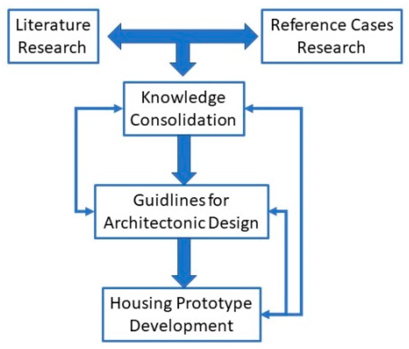
2. Methodology
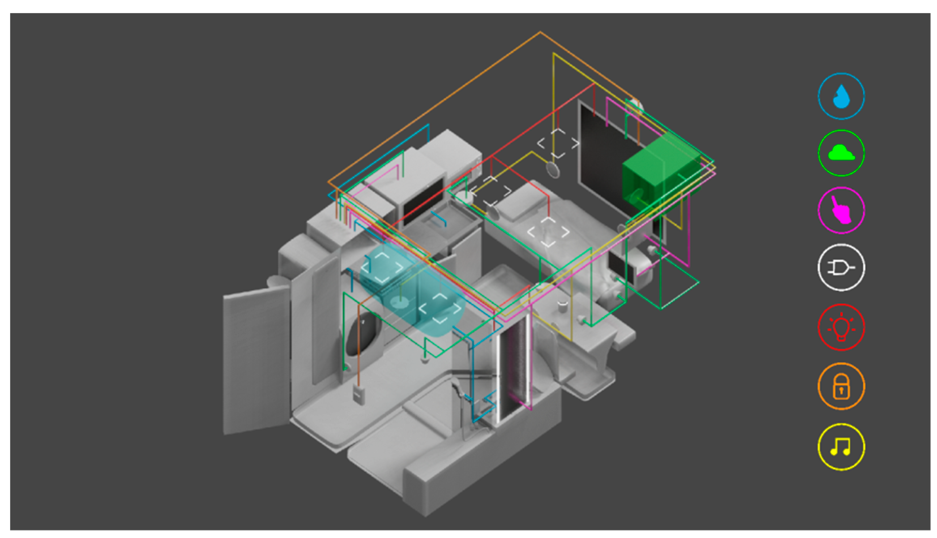
3. Building Automation System
3.1. Sensors and Actuators
3.2. Controllers
3.3. Interfaces
3.4. Communication Protocols
3.5. Network Topologies
3.6. Network Components and Devices
4. Results and Discussion
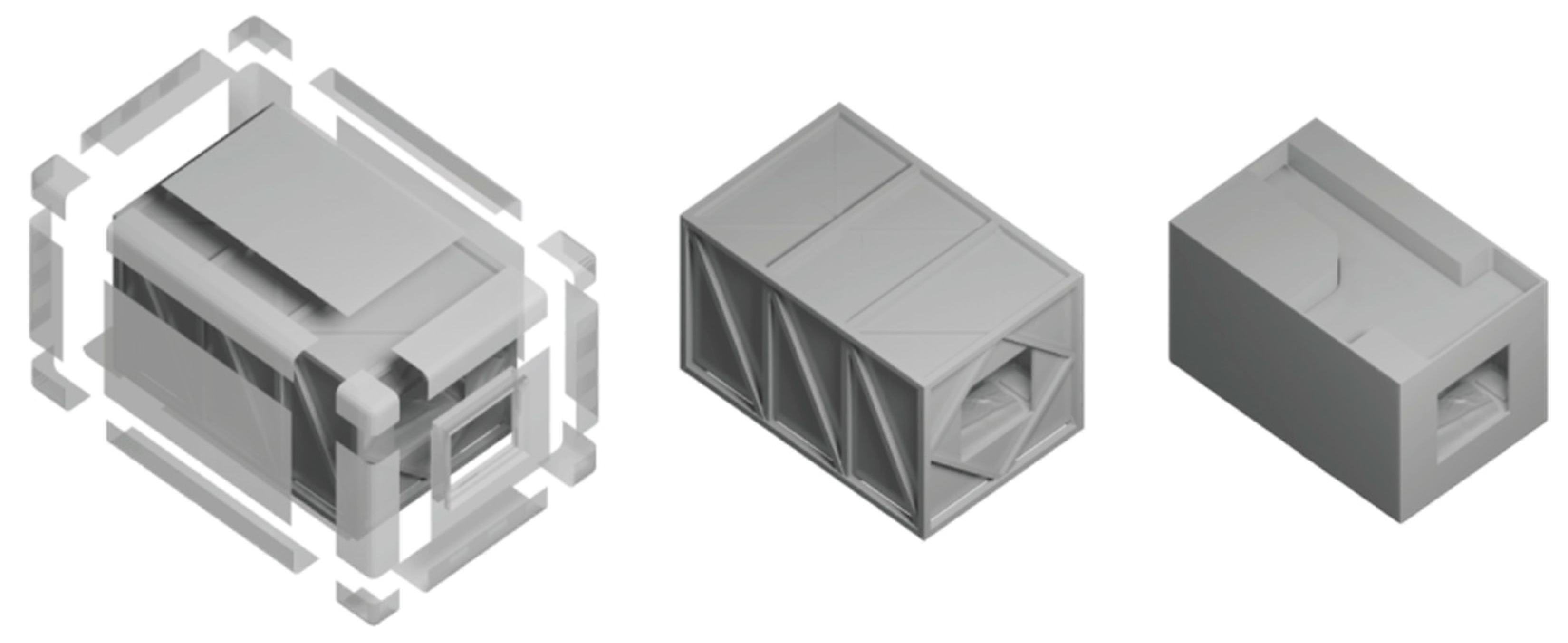
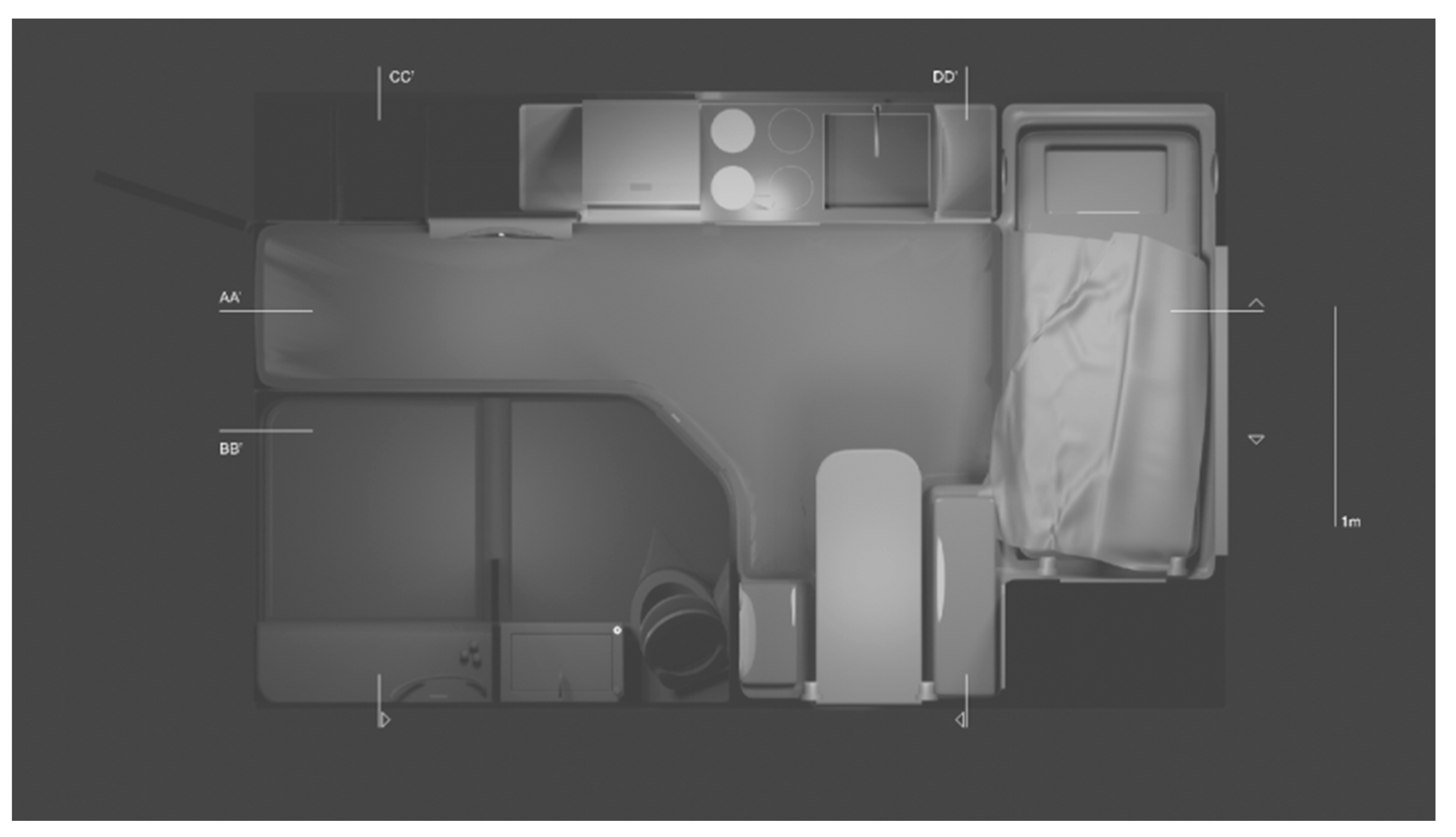
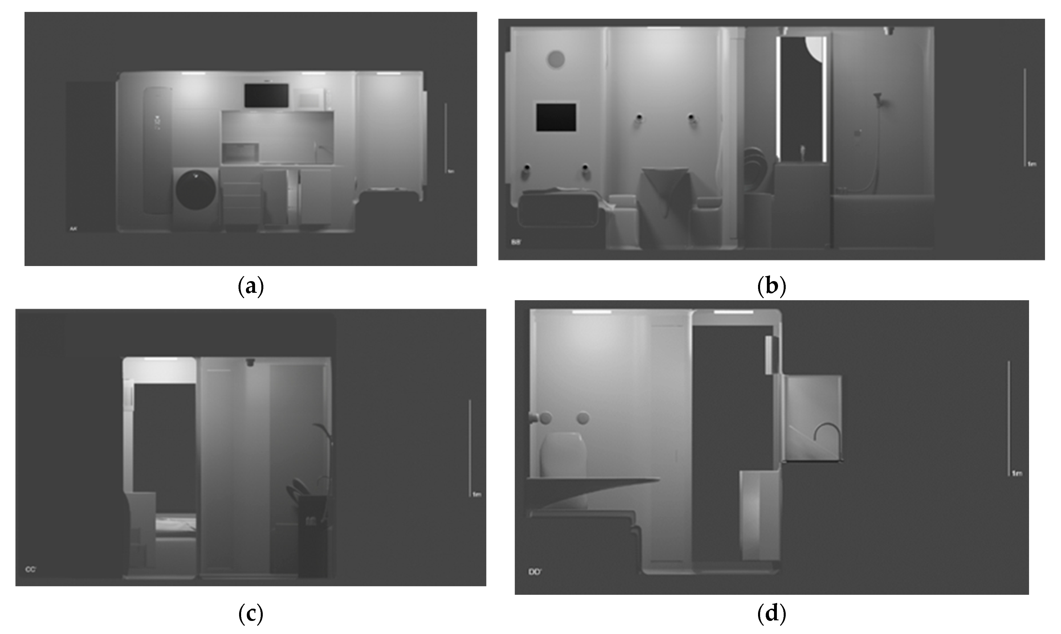
4.1. Housing Prototype
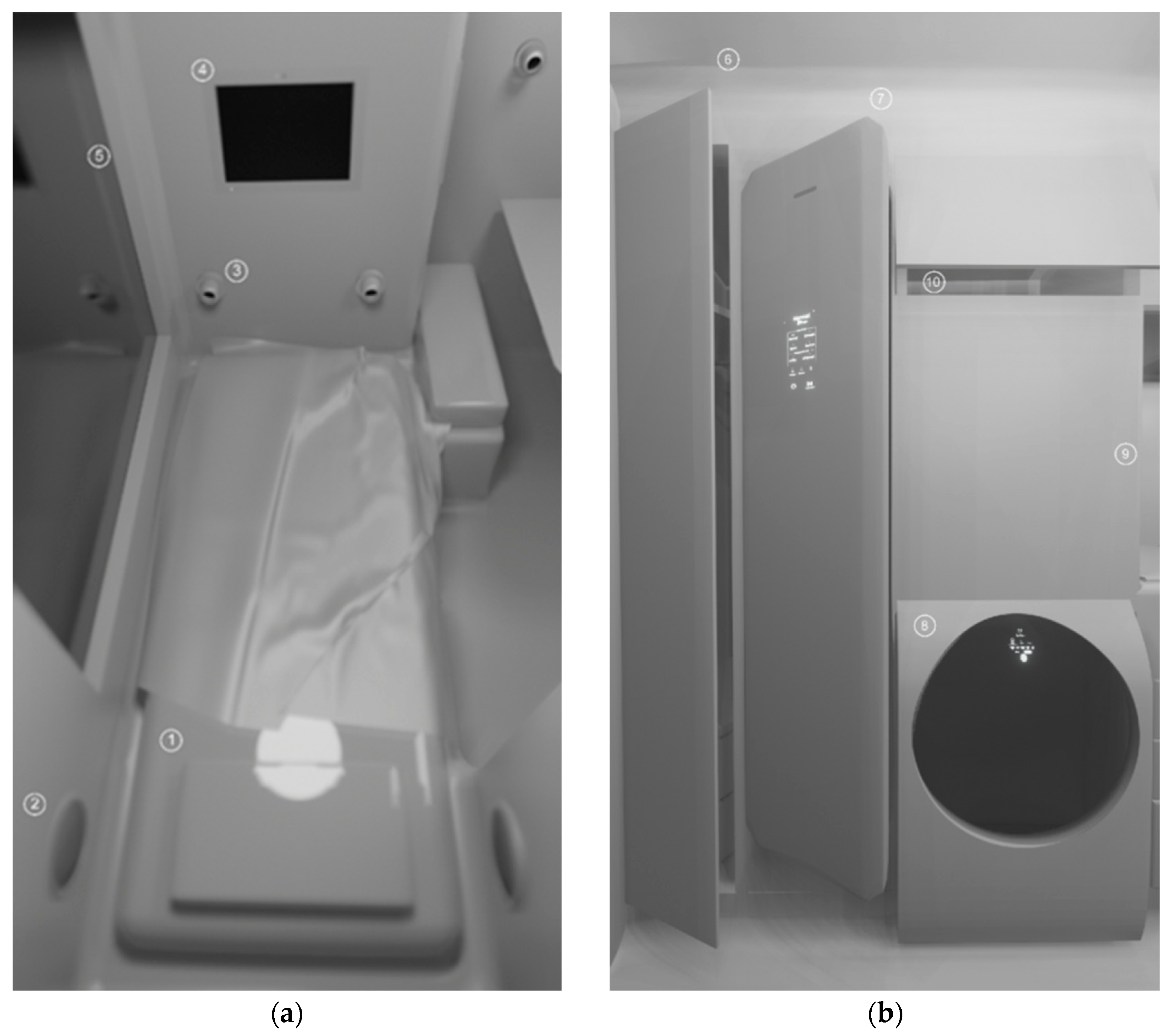
4.1.1. Bedroom
4.1.2. Textile and Laundry Area

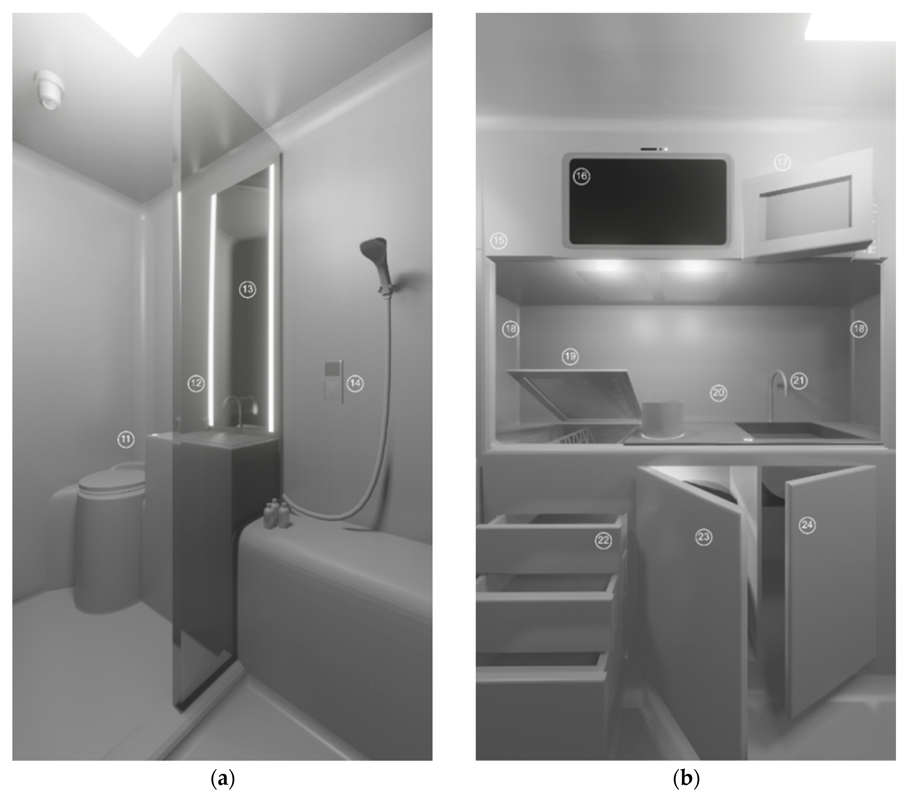
4.1.3. Personal Hygiene Area
4.1.4. Cooking Area
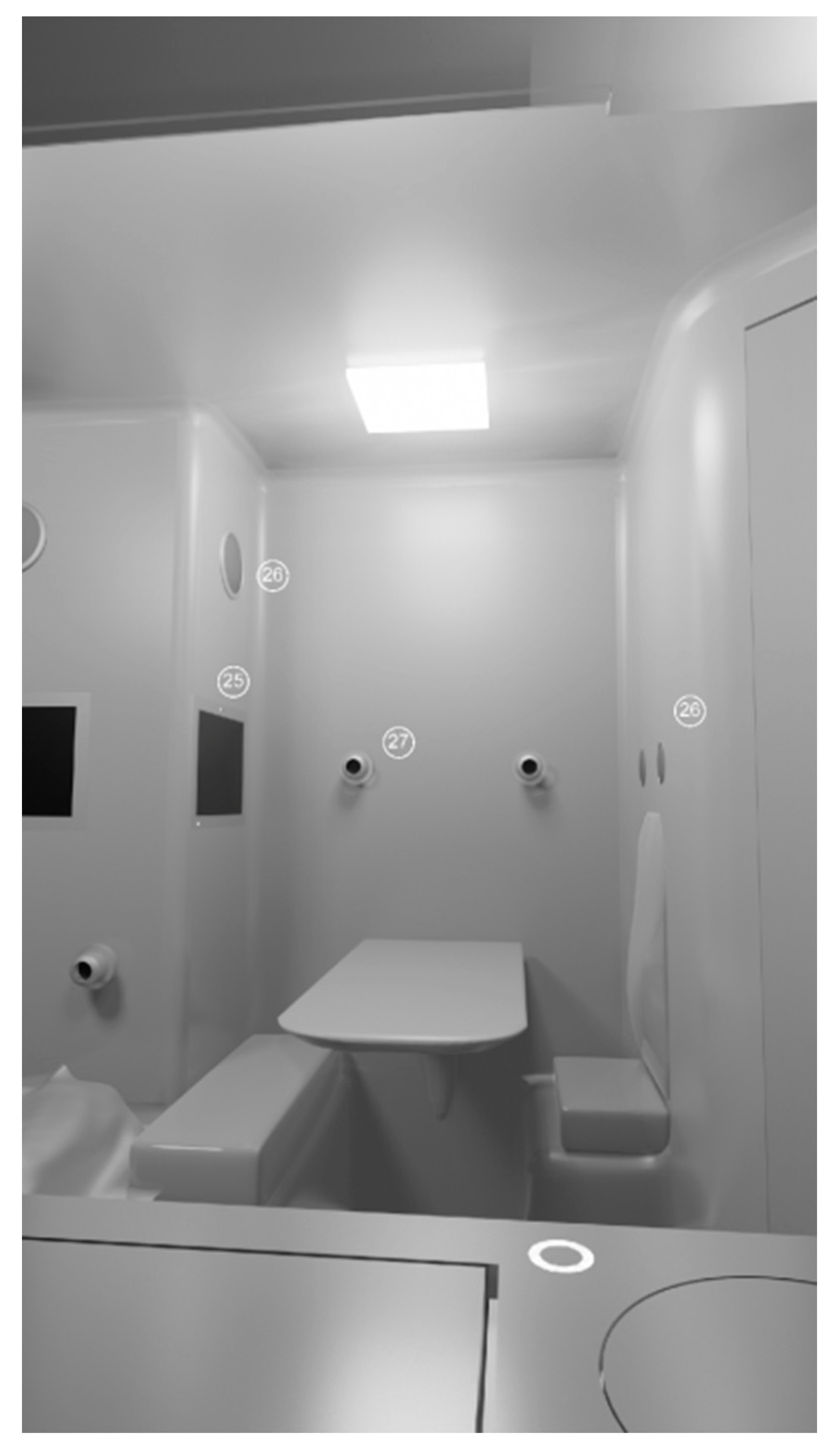
4.1.5. Work Area
4.2. Discussion
5. Conclusions
Author Contributions
Funding
Data Availability Statement
Conflicts of Interest
References
- Roser, M. Technology over the Long Run: Zoom out to See How Dramatically the World Can Change within a Lifetime. Available online: https://ourworldindata.org/technology-long-run (accessed on 31 March 2023).
- Coffin, M.J. Introduction to Direct Digital Control Systems. In Direct Digital Control for Building HVAC Systems; Springer: Boston, MA, USA, 1999. [Google Scholar] [CrossRef]
- Merz, H.; Hansemann, T.; Hübner, C. Building Automation—Communication Systems with EIB/KNX, LON and BACnet, 2nd ed.; Springer Nature: Mannheim, Germany, 2018. [Google Scholar]
- IEEE (Institute of Electrical and Electronics Engineers) Technology Navigator 2023. Solid State Devices. Available online: https://technav.ieee.org/topic/solid-state-devices (accessed on 31 March 2023).
- Martirano, L.; Mitolo, M. Building Automation and Control Systems (BACS): A Review. In Proceedings of the 2020 IEEE International Conference on Environment and Electrical Engineering and 2020 IEEE Industrial and Commercial Power Systems Europe (EEEIC/I&CPS Europe), Madrid, Spain, 9–12 June 2020. [Google Scholar] [CrossRef]
- Cohen-Almagor, R. Internet History. Int. J. Technoethics 2011, 2, 45–64. [Google Scholar] [CrossRef]
- Dennis, M.A.; Kahn, R. Internet Computer Network. 2023. Available online: https://www.britannica.com/technology/Internet (accessed on 3 April 2023).
- Serrenho, T.; Bertoldi, P. EUR 29750 EN; Smart Home and Appliances: State of the Art—Energy, Communications, Protocols, Standards. Publications Office of the European Union: Luxembourg, 2019. [CrossRef]
- Harper, R. Inside the smart home: Ideas, possibilities and methods. In Inside the Smart Home; Harper, R., Ed.; Springer: London, UK, 2003; pp. 1–13. [Google Scholar] [CrossRef]
- Dvoršak, B.; Havelka, J.; Mainardi, E.; Pandžić, H.; Selič, T.; Tretinjak, M. Smart Home Systems. This Publication is Part of the SHVET Project, Funded with Support from the European Commission. Available online: https://ec.europa.eu/programmes/erasmus-plus/project-result-content/4df4e928-8958-4552-80da-146977e666b9/Smart_Home_systems_FINAL.pdf (accessed on 22 April 2023).
- Simonet, C.; Noyce, A.J. Domotics, Smart Homes, and Parkinson’s Disease. J. Park. Dis. 2021, 11, S55–S63. [Google Scholar] [CrossRef] [PubMed]
- Bejarano, A.; Fernandez, B.; Jimeno, M.; Salazar, A.; Wightman, P. Towards the Evolution of Smart Home Environments: A Survey. Int. J. Autom. Smart Technol. 2016, 6, 105–136. [Google Scholar] [CrossRef]
- De Groote, M.; Volt, J.; Bean, F. Is Europe Ready for the Smart Buildings Revolution; Buildings Performance Institute Europe (BPIE): Brussels, Belgium, 2017. [Google Scholar]
- Gomes, I.B.; Ribeiro, J.T.; Macedo, C.L. Lisbon’s Águias Villa’s conversion into a hotel: Merging sustainability, architectural rehabilitation, and tourism concepts. Int. J. Architecton. Spat. Environ. Des. 2021, 15, 85–108. [Google Scholar] [CrossRef]
- Blender Foundation. Software Blender 2.7. Available online: https://www.blender.org/ (accessed on 22 November 2020).
- Kastner, W.; Neugschwandtner, G.; Soucek, S.; Newman, H.M. Communication systems for building automation and control. Proc. IEEE 2005, 93, 1178–1203. [Google Scholar] [CrossRef]
- Domingues, P.; Carreira, P.; Vieira, R.; Kastner, W. Building automation systems: Concepts and technology review. Comput. Stand. Interfaces 2016, 45, 12. [Google Scholar] [CrossRef]
- Miori, V.; Russo, D. Domotic evolution towards the IoT. In International Conference on Advanced Information Networking and Applications Workshops; IEEE: Victoria, BC, Canada, 2014; pp. 809–814. [Google Scholar]
- Nývlt, O. Buses, Protocols and Systems for Home and Building Automation; Department of Control Engineering Faculty of Electrical Engineering Czech Technical University in Prague: Prague, Czech Republic, 2009–2011. [Google Scholar]
- Thakur, M.; Verma, P. A Review of Computer Network Topology and Analysis Examples. Int. J. Adv. Eng. Manag. 2022, 4, 1523–1530. [Google Scholar] [CrossRef]
- Bird, D.; Harwood, M. Network+ Training Guide; Que Publishing: Indianapolis, IN, Canada, 2003. [Google Scholar]
- Corbusier, L. Towards A New Architecture; Dover Publications Inc.: New York, NY, USA, 1986. [Google Scholar]
- Seelow, A.M. Function and Form: Shifts in Modernist Architects’ Design Thinking. Arts 2017, 6, 1. [Google Scholar] [CrossRef] [Green Version]
- Brysch, S. Reinterpreting Existenzminimum in Contemporary Affordable Housing Solutions. Urban Plan. 2019, 4, 1–20. [Google Scholar] [CrossRef] [Green Version]
- Ishida, A. Metabolic impermanence: The Nakagin capsule tower. Inflection J. 2017, 4, 32–43. [Google Scholar]
- Tamura, T.; Kawarada, A.; Nambu, M.; Tsukada, A.; Sasaki, K.; Yamakoshi, K.-I. E-Healthcare at an Experimental Welfare Techno House in Japan. Open Med. Inform. J. 2007, 1, 1–7. [Google Scholar] [CrossRef] [PubMed] [Green Version]
- Brooks, R.A. The Intelligent Room Project. In Proceedings of the Second International Conference on Cognitive Technology Humanizing the Information Age, Aizu-Wakamatsu, Japan, 25–28 August 1997; IEEE: Piscataway, NJ, USA, 1999. [Google Scholar] [CrossRef] [Green Version]
- Cook, D.J.; Youngblood, M.; Heierman, E.O.; Gopalratnam, K.; Rao, S.; Litvin, A.; Khawaja, F. MavHome: An agent-based smart home. In Proceedings of the First IEEE International Conference on Pervasive Computing and Communications, Fort Worth, TX, USA, 26 March 2003; IEEE: Piscataway, NJ, USA, 2003. [Google Scholar] [CrossRef]
- Yamazaki, T. The Ubiquitous Home. Int. J. Smart Home 2007, 1, 17–22. [Google Scholar]
- Pospisil, M. EcoCapsule, self-sustainable microhome. In Proceedings of the DARCH 2021 1st International Conference on Architecture & Design. International Organization Center of Academic Research, Online, 12–13 July 2021; pp. 85–91. [Google Scholar]
- Krueger, T. Metadermis: Like a second skin. In Architecture—Machine and Body: Notes on the New Technology in Architecture; Afonso, R.B., Furtado, G., Eds.; Carneiro, A.; Peck, B.; Alves, I., Translators; FAUP: Porto, Portugal, 2006; pp. 87–98. [Google Scholar]


| Network Topology | Description | Advantages | Disadvantages |
|---|---|---|---|
| Bus | a single cable is used to connect all the devices on the network | easy installation and minimal cabling required; | performance limitations on the number of network nodes; |
| failure of one node does not affect other nodes; | network connectivity shut down when the cable fails. | ||
| messages from one node can be seen simultaneously by all other nodes. | |||
| Ring | each node is connected to two other nodes, and the last is connected to the first | relatively long transmission time between nodes; | |
| messages sent in one direction or both directions (using two cables between each connected node); | cabling failure between two nodes has a broader effect on the entire network; | ||
| commonly used in networks with low inter-node traffic | relative communication delays between nodes; | ||
| network expansion or reconfiguration requires new cabling | |||
| Star | requires the use of a top-level central node to which all other nodes are connected | reduced messaging delay between nodes; | need for more wires; |
| a connection failure between a higher-level node and any of its subordinate nodes, or failure of one subordinate node, will not affect the entire network; | a failure of the top-level node will disrupt all communication on the network | ||
| cabling failures location; | a limited number of higher-level node connections | ||
| often used in LANs with larger geometrical area | |||
| Tree | built by creating a set of star topologies below a central node or by connecting a set of star topologies directly through a bus | easy network scaled; | |
| cabling fault location; | a higher-level node failure or the cable connection failure, then the partial network will be lost to communication. | ||
| expansion can be as simple as attaching an additional star network topology to the bus | |||
| Mesh | full—each node is directly connected to all other nodes; section—has a number of network nodes that are indirectly connected to other nodes | path redundancy; | |
| for high traffic between nodes; | high cost of setting up the network; | ||
| reduced probability of single-point network failure; | each node needs a routing algorithm to compute the path | ||
| source nodes define the best route from sender to destination | |||
| wireless suitable |
Disclaimer/Publisher’s Note: The statements, opinions and data contained in all publications are solely those of the individual author(s) and contributor(s) and not of MDPI and/or the editor(s). MDPI and/or the editor(s) disclaim responsibility for any injury to people or property resulting from any ideas, methods, instructions or products referred to in the content. |
© 2023 by the authors. Licensee MDPI, Basel, Switzerland. This article is an open access article distributed under the terms and conditions of the Creative Commons Attribution (CC BY) license (https://creativecommons.org/licenses/by/4.0/).
Share and Cite
Racha-Pacheco, P.; Ribeiro, J.T.; Afonso, J. Architecture towards Technology—A Prototype Design of a Smart Home. Buildings 2023, 13, 1859. https://doi.org/10.3390/buildings13071859
Racha-Pacheco P, Ribeiro JT, Afonso J. Architecture towards Technology—A Prototype Design of a Smart Home. Buildings. 2023; 13(7):1859. https://doi.org/10.3390/buildings13071859
Chicago/Turabian StyleRacha-Pacheco, Pedro, Jorge T. Ribeiro, and José Afonso. 2023. "Architecture towards Technology—A Prototype Design of a Smart Home" Buildings 13, no. 7: 1859. https://doi.org/10.3390/buildings13071859