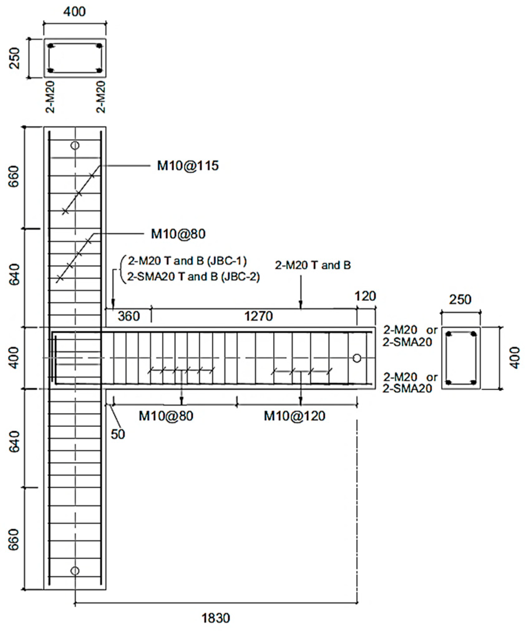
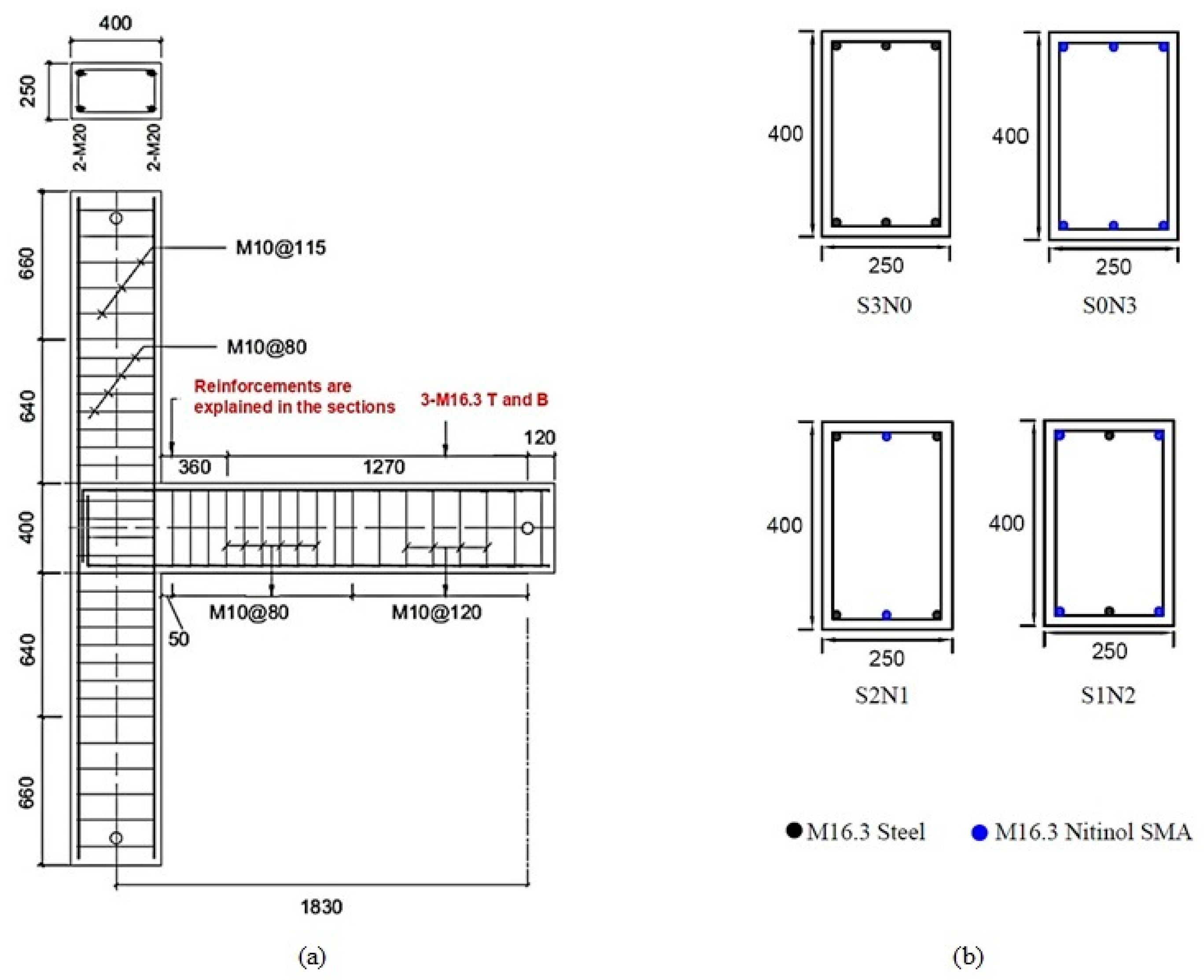
Figure 1.
Reinforcement details of specimens, steel-BCJ and SMA-BCJ (all dimensions in mm). Reprinted from [
19], with permission from Taylor and Francis.
Figure 1.
Reinforcement details of specimens, steel-BCJ and SMA-BCJ (all dimensions in mm). Reprinted from [
19], with permission from Taylor and Francis.
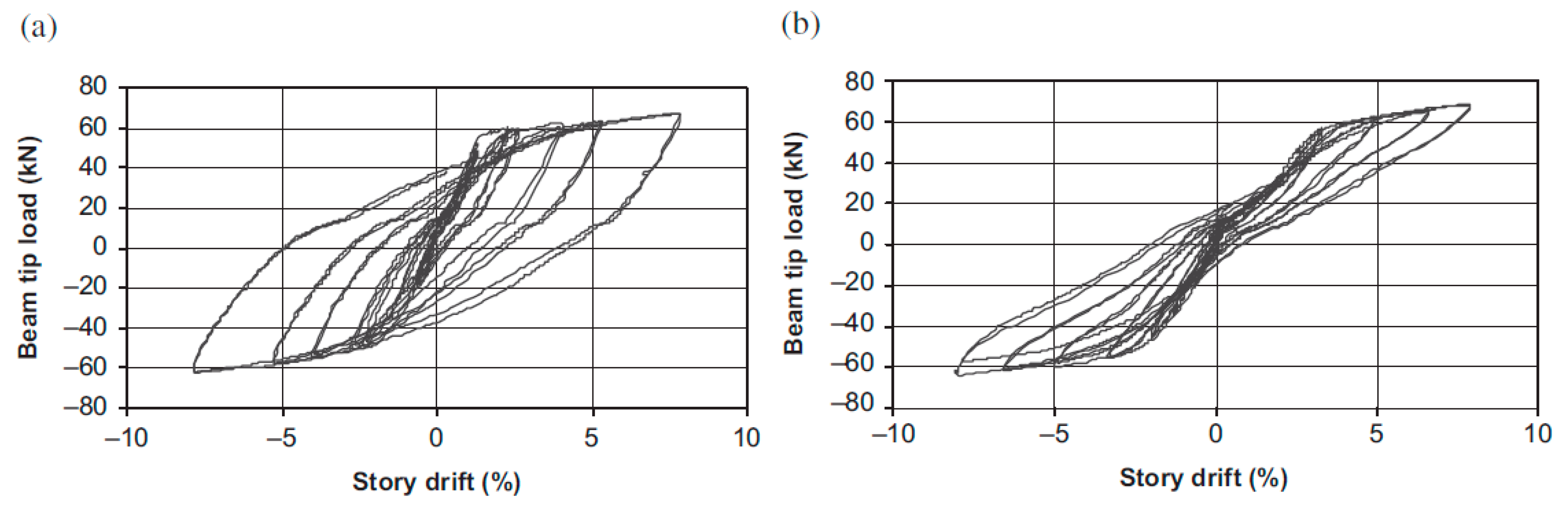
Figure 2.
Beam tip load–story drift relationship of specimens: (
a) steel-BCJ and (
b) SMA-BCJ. Reprinted from [
19], with permission from Taylor and Francis.
Figure 2.
Beam tip load–story drift relationship of specimens: (
a) steel-BCJ and (
b) SMA-BCJ. Reprinted from [
19], with permission from Taylor and Francis.
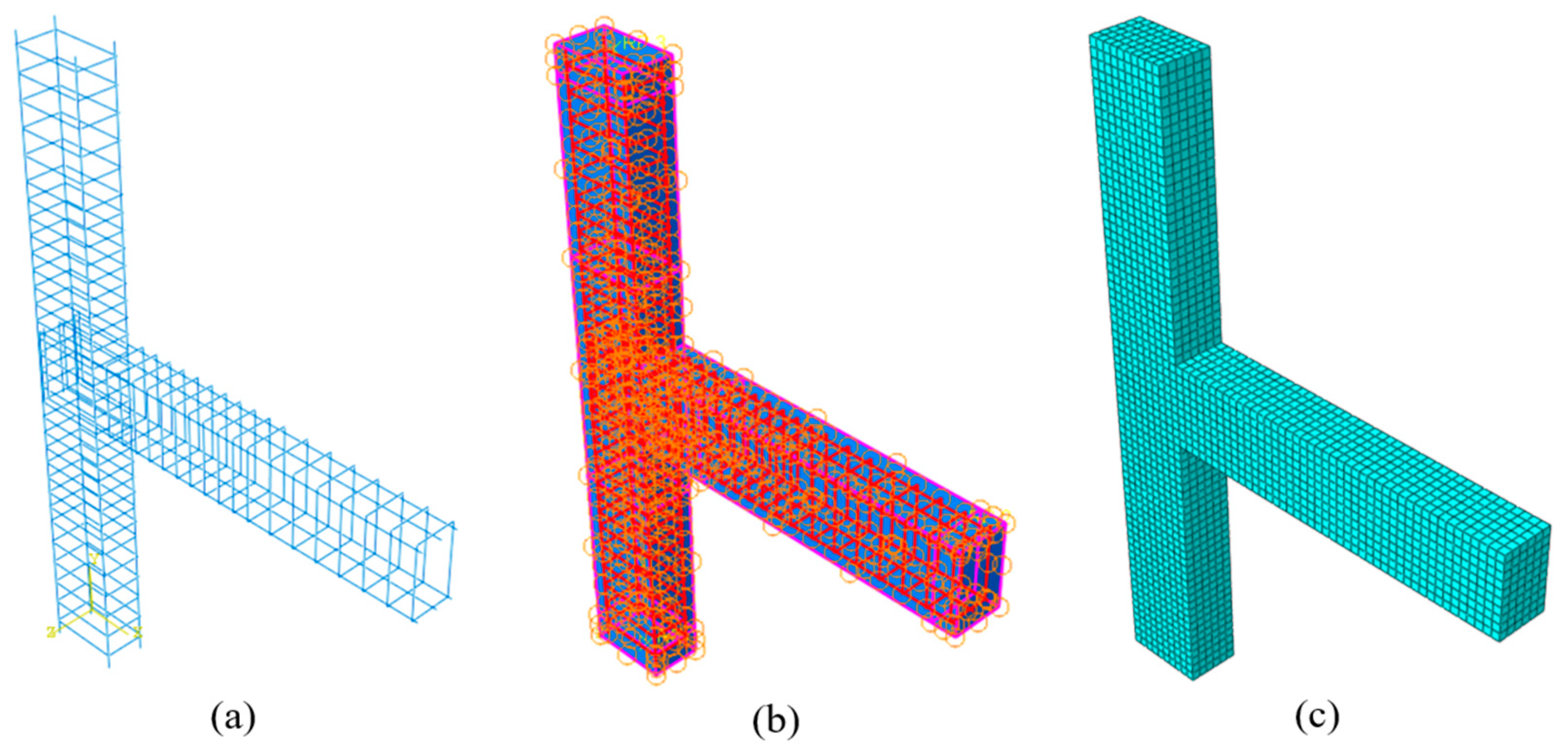
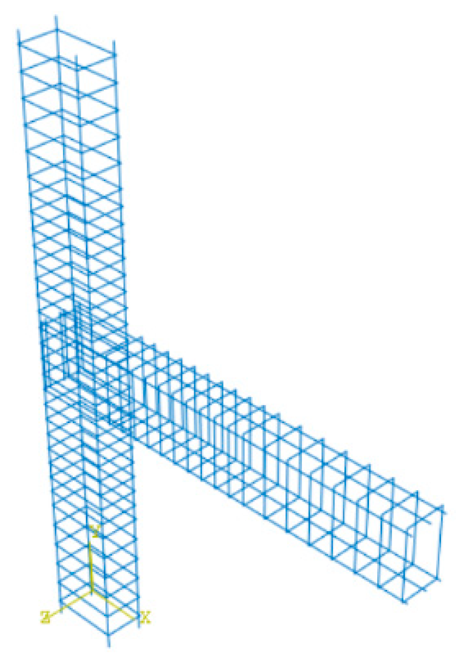
Figure 3.
(a) Reinforcement of RC beam column joint. (b) Embedded region contact between concrete and reinforcement. (c) Typical finite element mesh of RC-BCJ.
Figure 3.
(a) Reinforcement of RC beam column joint. (b) Embedded region contact between concrete and reinforcement. (c) Typical finite element mesh of RC-BCJ.
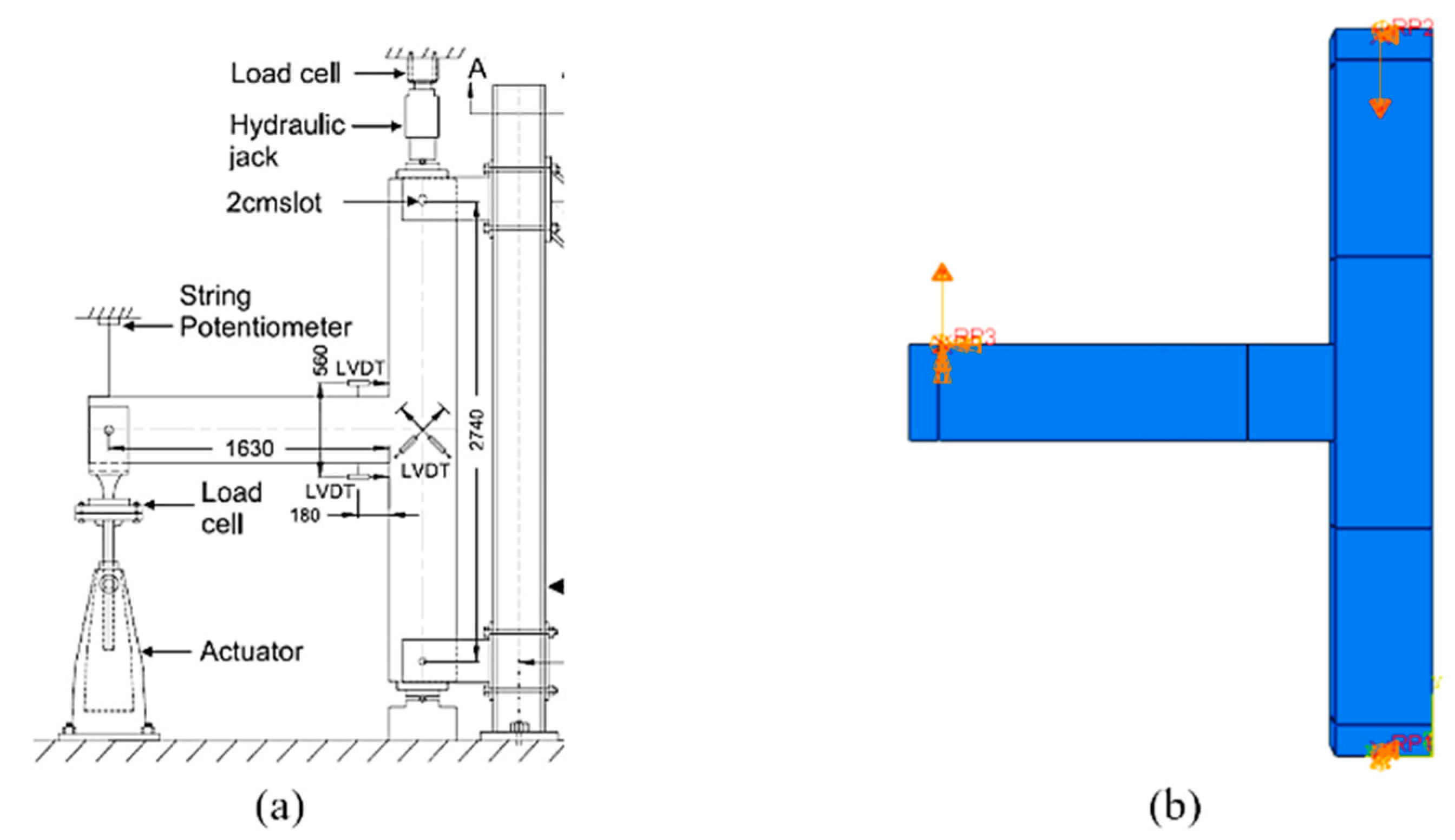
Figure 4.
Boundary conditions of RC-BCJ: (
a) experimental, reprinted from [
19], with permission from Taylor and Francis. (
b) Numerical.
Figure 4.
Boundary conditions of RC-BCJ: (
a) experimental, reprinted from [
19], with permission from Taylor and Francis. (
b) Numerical.
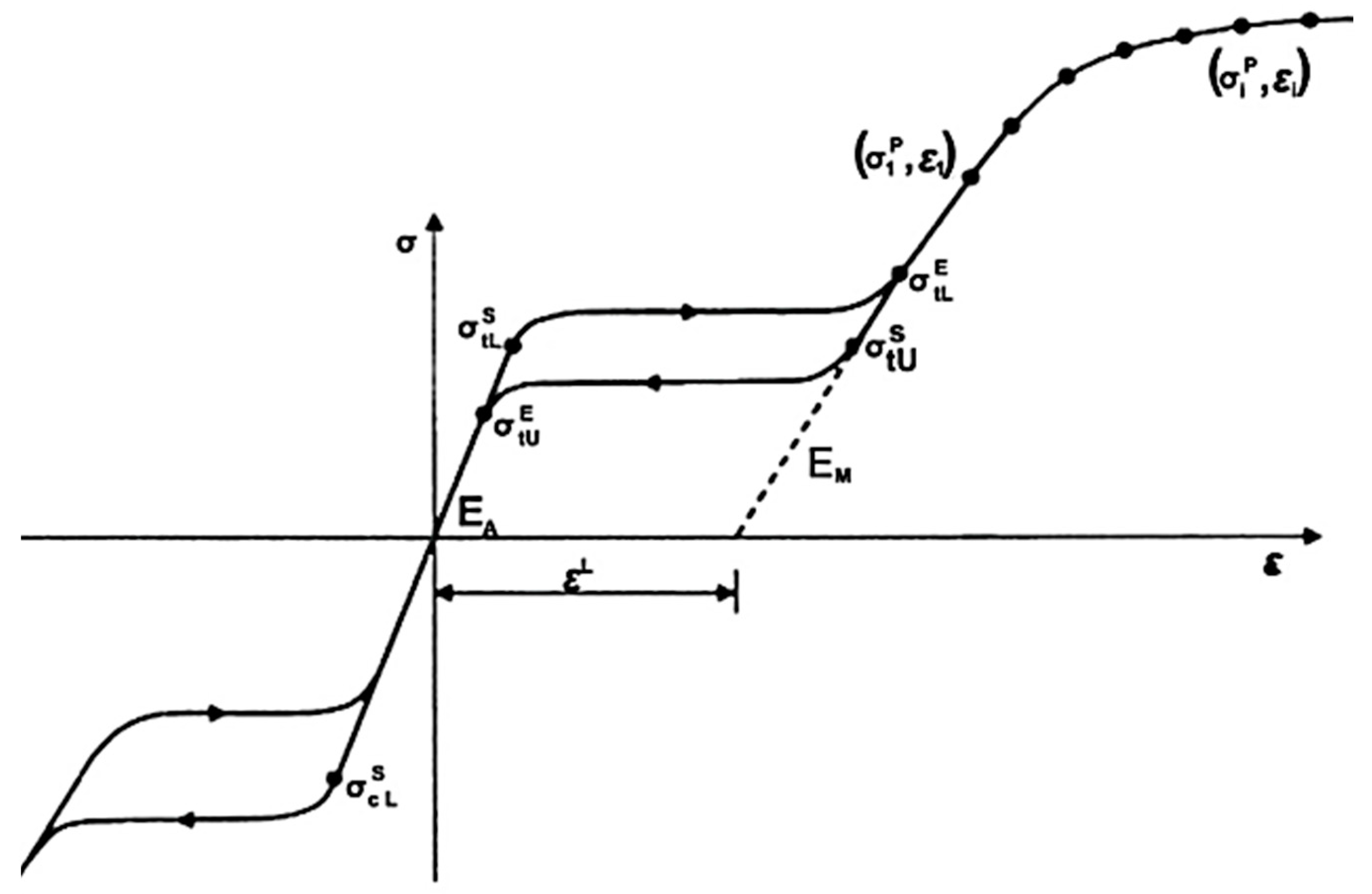
Figure 5.
Performance of superelastic material under uniaxial tension (ABAQUS Manual). Reprinted from [
21], with permission from Creative Commons Attribution (CC BY) license.
Figure 5.
Performance of superelastic material under uniaxial tension (ABAQUS Manual). Reprinted from [
21], with permission from Creative Commons Attribution (CC BY) license.
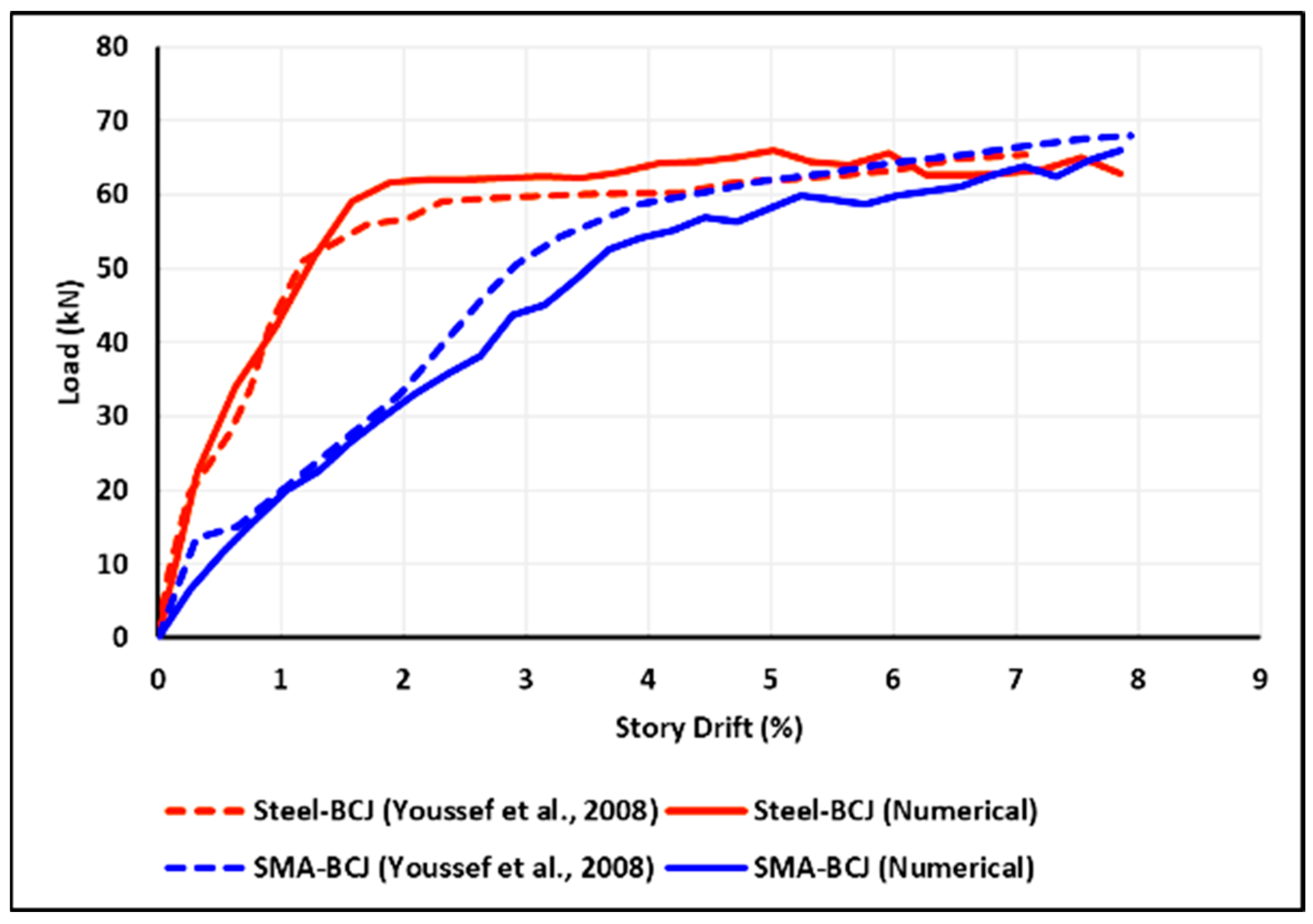
Figure 6.
Experimental and numerical beam tip-load versus story drift envelope for the specimens steel-BCJ and SMA-BCJ [
19].
Figure 6.
Experimental and numerical beam tip-load versus story drift envelope for the specimens steel-BCJ and SMA-BCJ [
19].
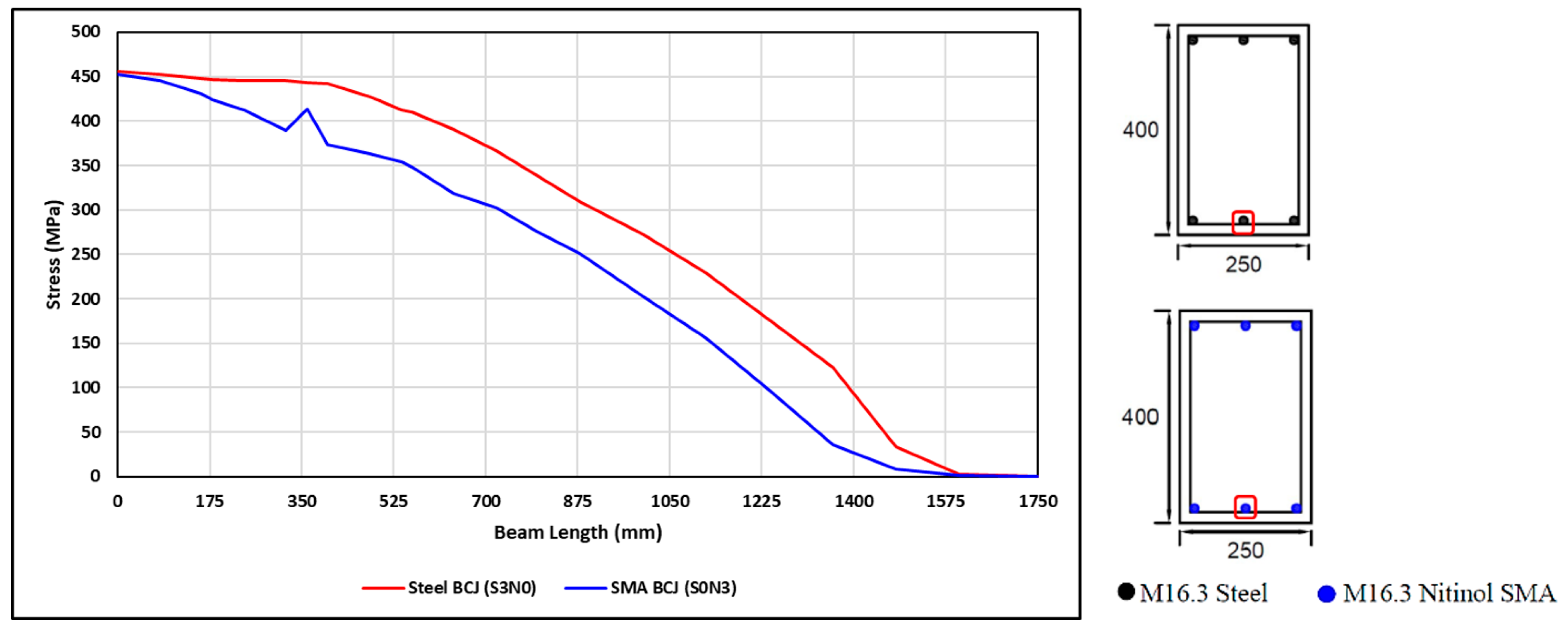
Figure 7.
(a) Typical reinforcement details of the specimens. (b) Reinforcement details at the plastic hinge of RC-BCJ specimens (all dimensions in mm).
Figure 7.
(a) Typical reinforcement details of the specimens. (b) Reinforcement details at the plastic hinge of RC-BCJ specimens (all dimensions in mm).
Figure 8.
Reinforcement RC-BCJ as obtained from FE.
Figure 8.
Reinforcement RC-BCJ as obtained from FE.
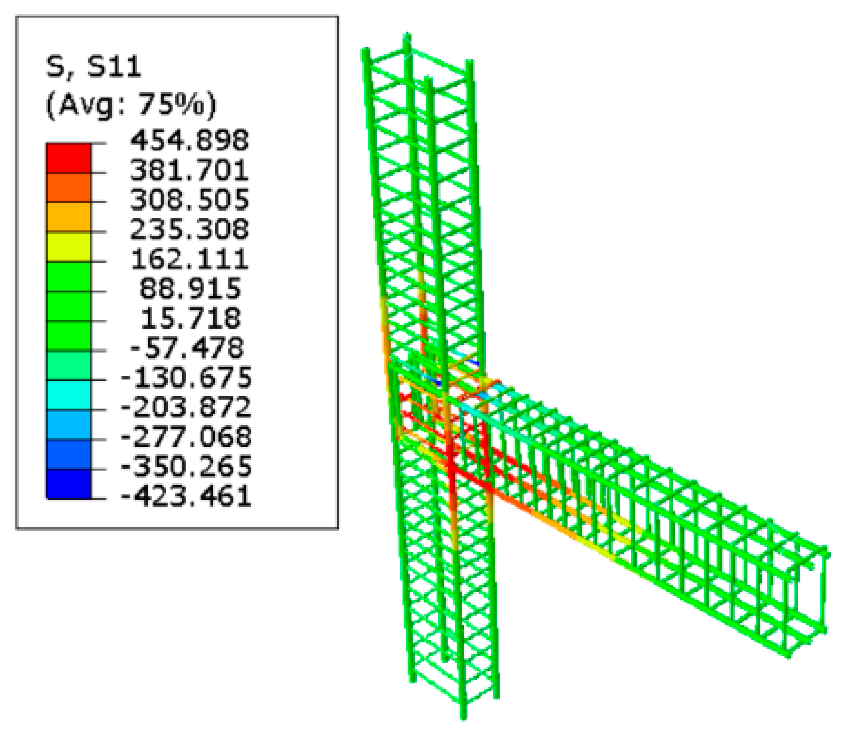
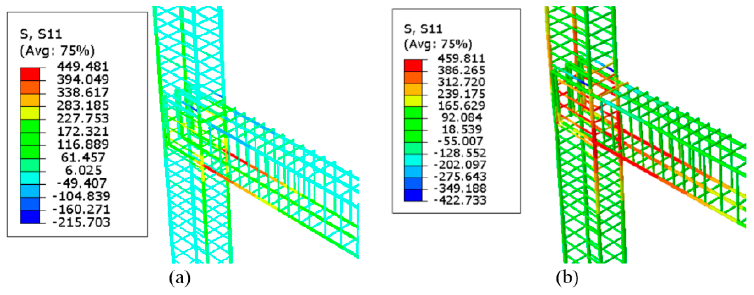
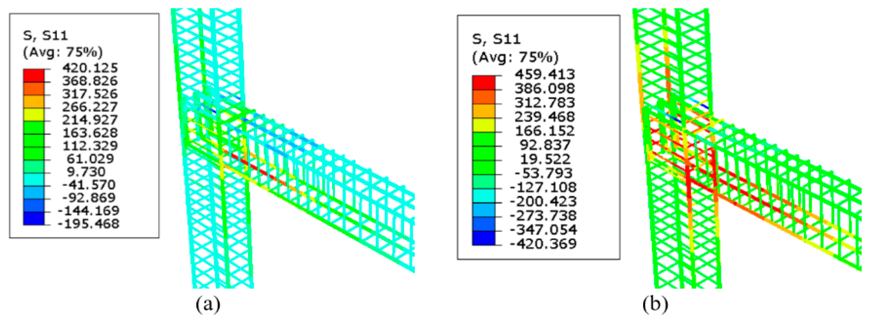
Figure 9.
Stress in the reinforcement RC-BCJ as obtained from FE.
Figure 9.
Stress in the reinforcement RC-BCJ as obtained from FE.
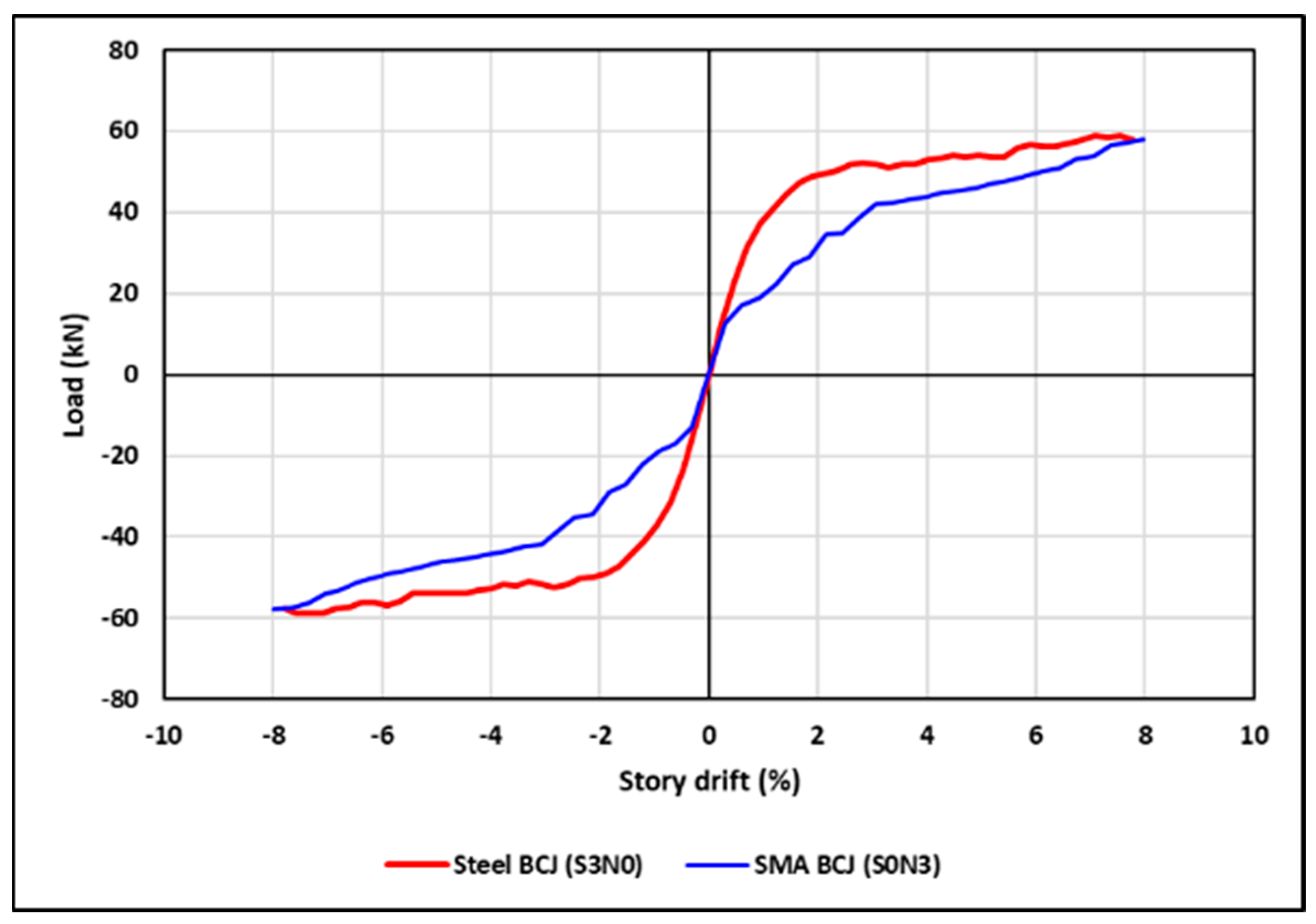
Figure 10.
Numerical beam tip-load versus story drift envelope of the specimens C25-A0-S3N0 and C25-A0-S0N3.
Figure 10.
Numerical beam tip-load versus story drift envelope of the specimens C25-A0-S3N0 and C25-A0-S0N3.
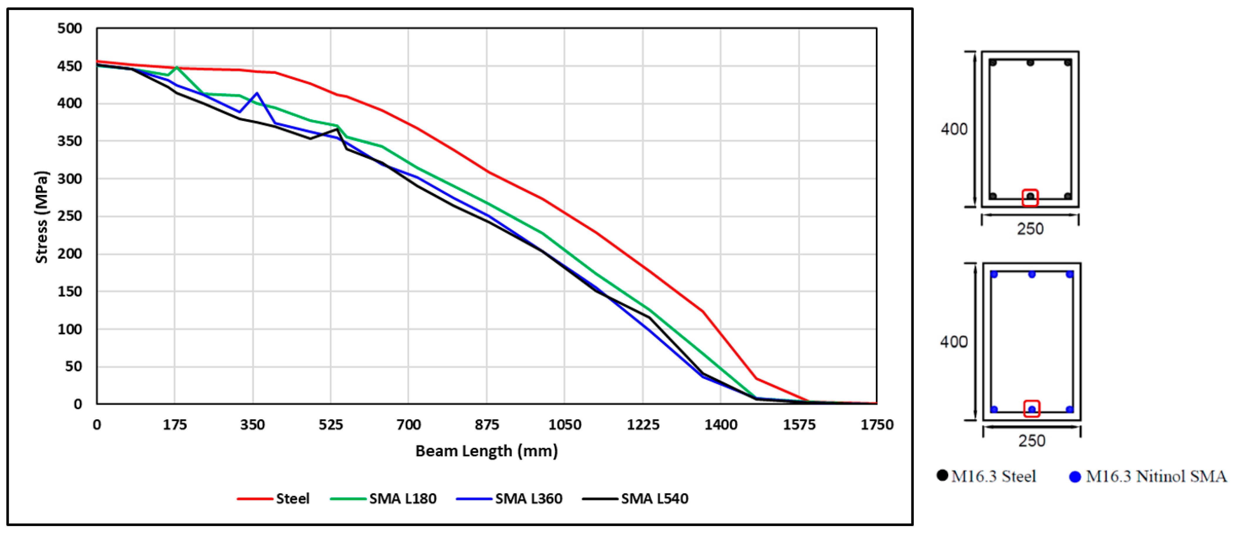
Figure 11.
Stress of the beam reinforcement rebar under monotonic pull loading versus the span length of the beam at 8% drift.
Figure 11.
Stress of the beam reinforcement rebar under monotonic pull loading versus the span length of the beam at 8% drift.
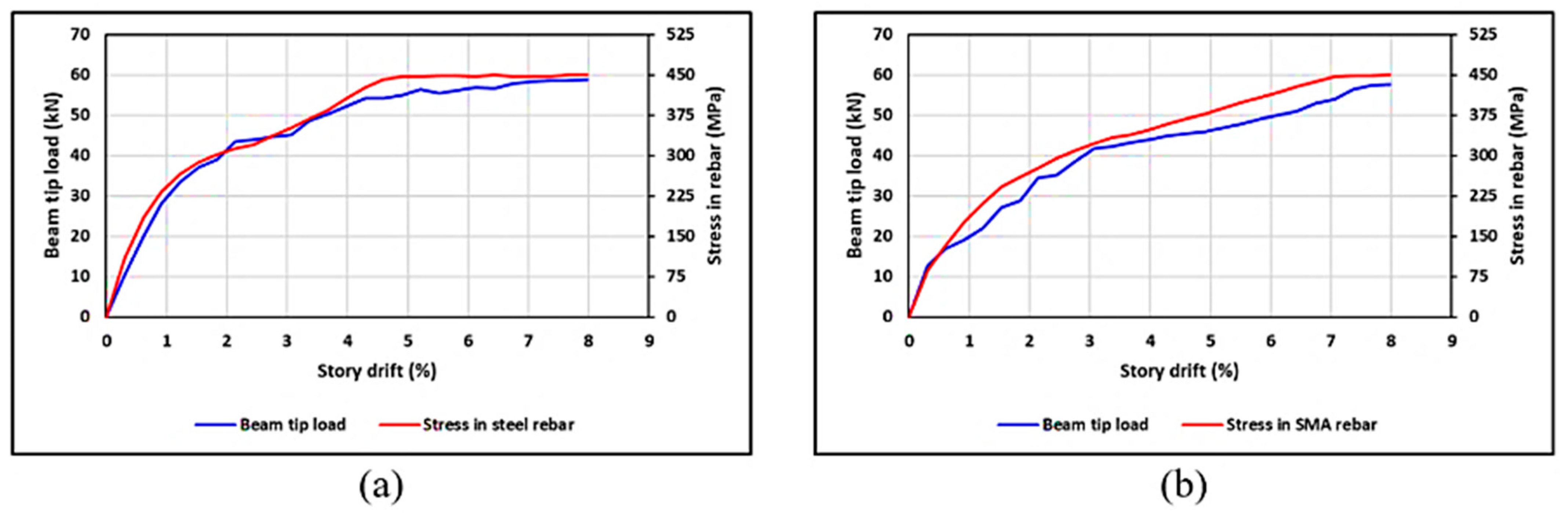
Figure 12.
Comparisons of the numerical beam tip load and stresses in rebars versus story drift of the specimens: (a) C25-A0-S3N0 and (b) C25-A0-S0N3.
Figure 12.
Comparisons of the numerical beam tip load and stresses in rebars versus story drift of the specimens: (a) C25-A0-S3N0 and (b) C25-A0-S0N3.
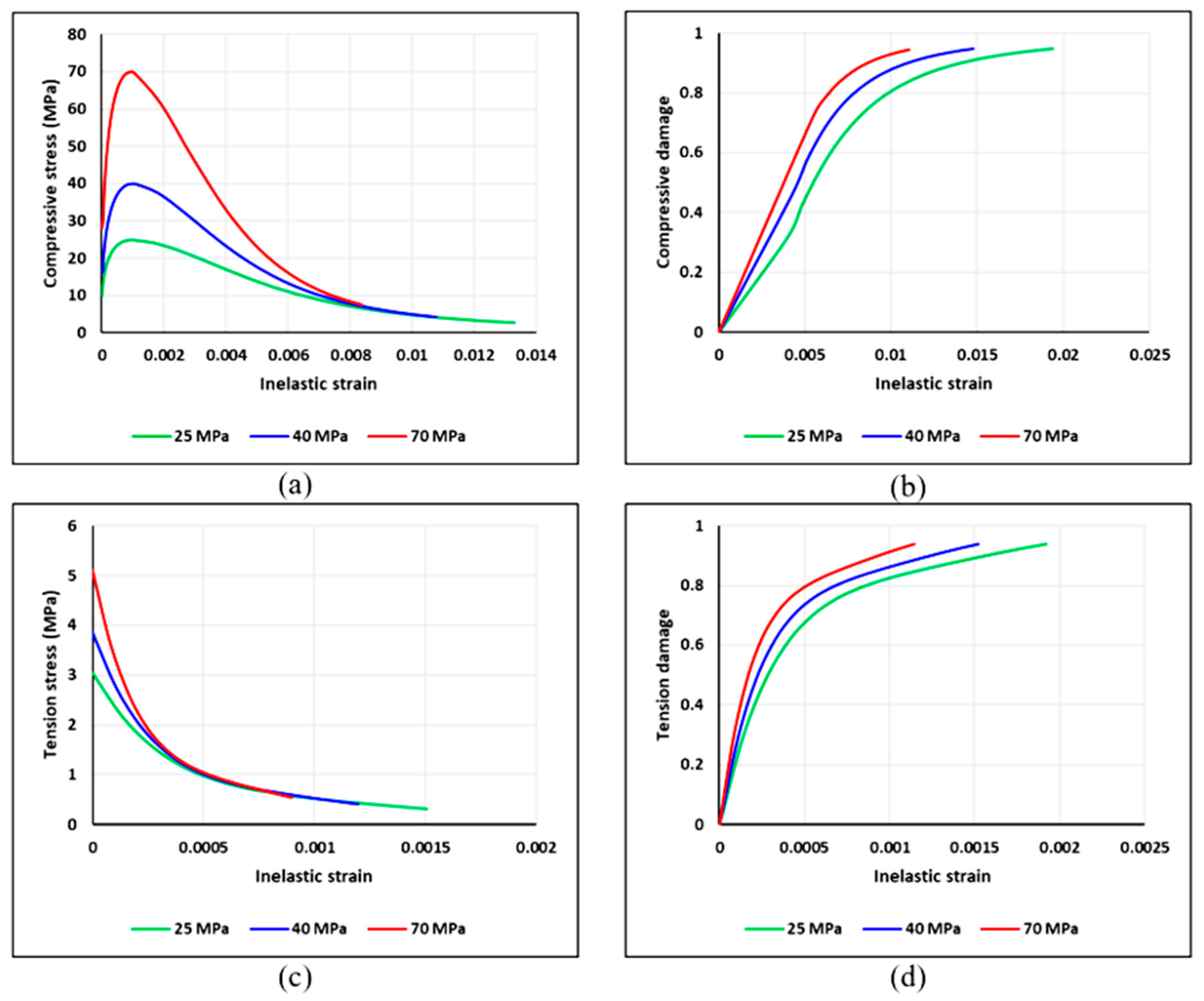
Figure 13.
Definition of concrete damage–plasticity model parameters in ABAQUS: (a) compressive stress vs. inelastic strain, (b) compressive damage vs. inelastic strain, (c) tensile stress vs. cracking strain, and (d) tensile damage vs. cracking strain.
Figure 13.
Definition of concrete damage–plasticity model parameters in ABAQUS: (a) compressive stress vs. inelastic strain, (b) compressive damage vs. inelastic strain, (c) tensile stress vs. cracking strain, and (d) tensile damage vs. cracking strain.
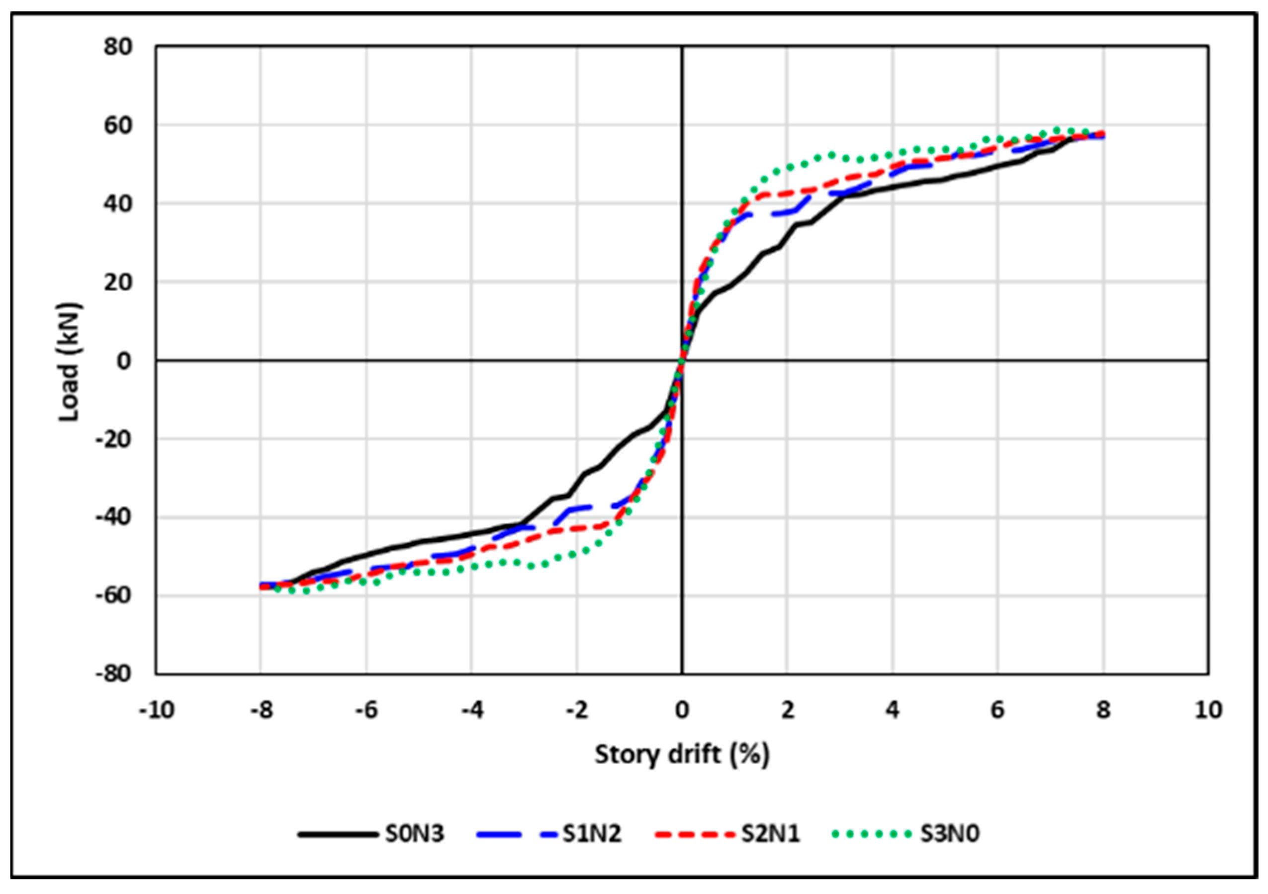
Figure 14.
Numerical beam tip-load versus story drift envelopes of the C25-A0-S3N0, C25-A0-S1N2, C25-A0-S2N1, and C25-A0-S0N3 specimens.
Figure 14.
Numerical beam tip-load versus story drift envelopes of the C25-A0-S3N0, C25-A0-S1N2, C25-A0-S2N1, and C25-A0-S0N3 specimens.
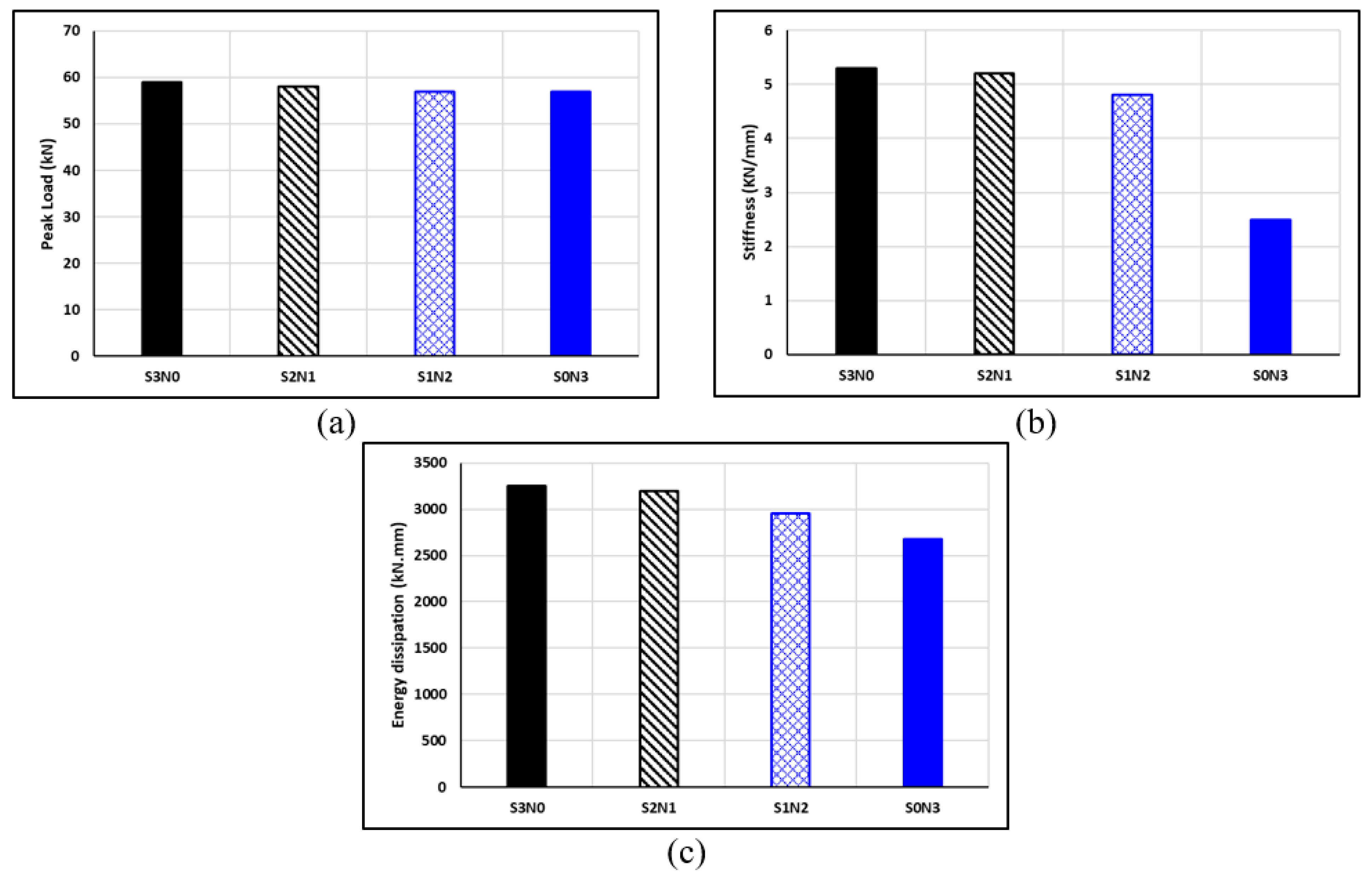
Figure 15.
Effect of SMA-steel reinforcement ratios of the BCJ on (a) load capacity, (b) stiffness, and (c) energy dissipation.
Figure 15.
Effect of SMA-steel reinforcement ratios of the BCJ on (a) load capacity, (b) stiffness, and (c) energy dissipation.
Figure 16.
Stresses of steel and SMA rebars of S2N1 specimen during push loading at (a) 2.8% story drift and (b) 8% story drift.
Figure 16.
Stresses of steel and SMA rebars of S2N1 specimen during push loading at (a) 2.8% story drift and (b) 8% story drift.
Figure 17.
Stresses of steel and SMA rebars in S1N2 specimen during push loading at (a) 2.8% story drift and (b) 8% story drift.
Figure 17.
Stresses of steel and SMA rebars in S1N2 specimen during push loading at (a) 2.8% story drift and (b) 8% story drift.
Figure 18.
Stress of the beam reinforcement rebar using different lengths of SMA under monotonic pull loading versus the beam length at 8% drift.
Figure 18.
Stress of the beam reinforcement rebar using different lengths of SMA under monotonic pull loading versus the beam length at 8% drift.
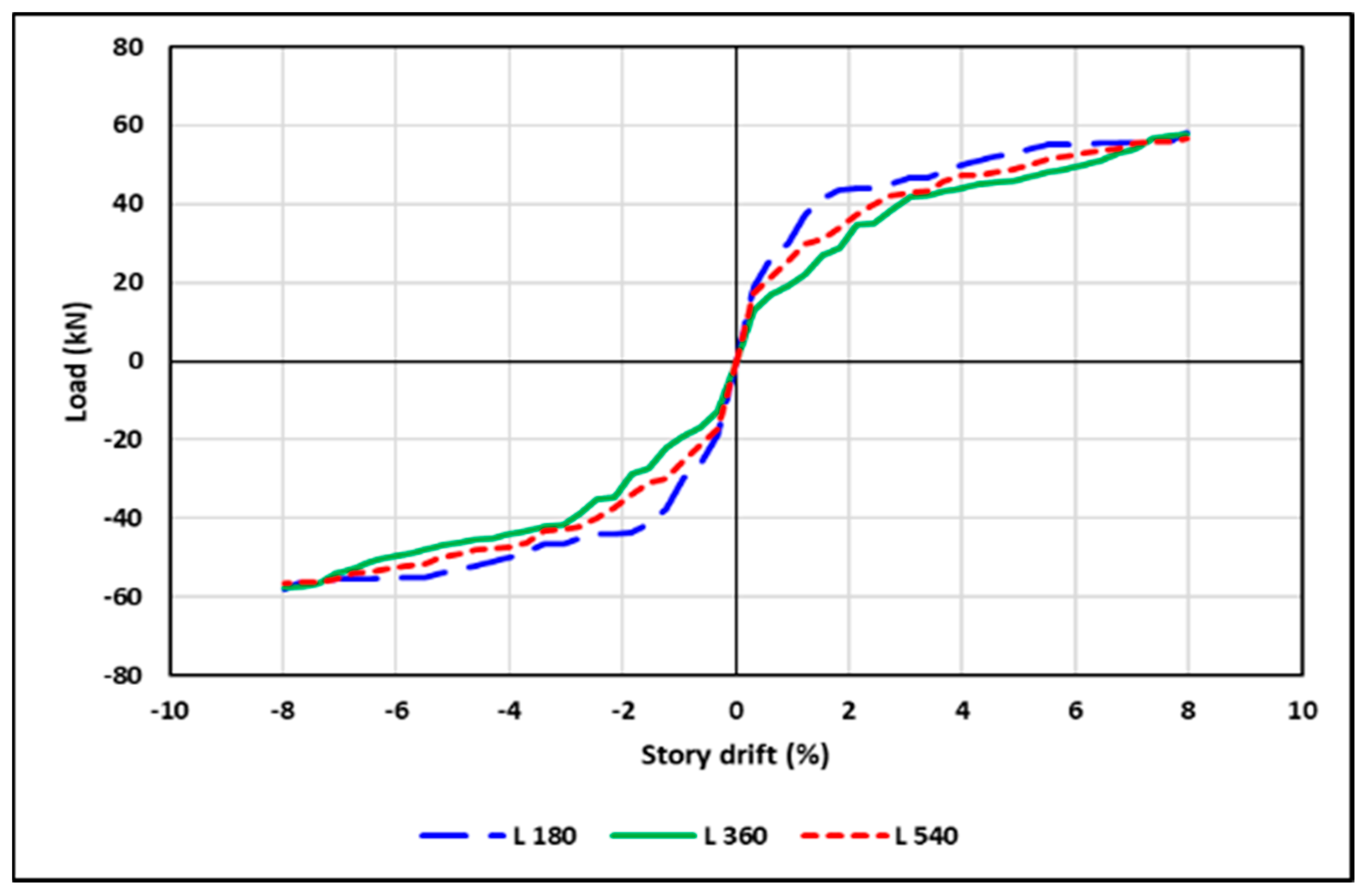
Figure 19.
Numerical beam tip-load versus story drift envelopes of the specimens C25-A0-S0N3, C25-A0-S0N3-L180 and C25-A0-S0N3-L540.
Figure 19.
Numerical beam tip-load versus story drift envelopes of the specimens C25-A0-S0N3, C25-A0-S0N3-L180 and C25-A0-S0N3-L540.
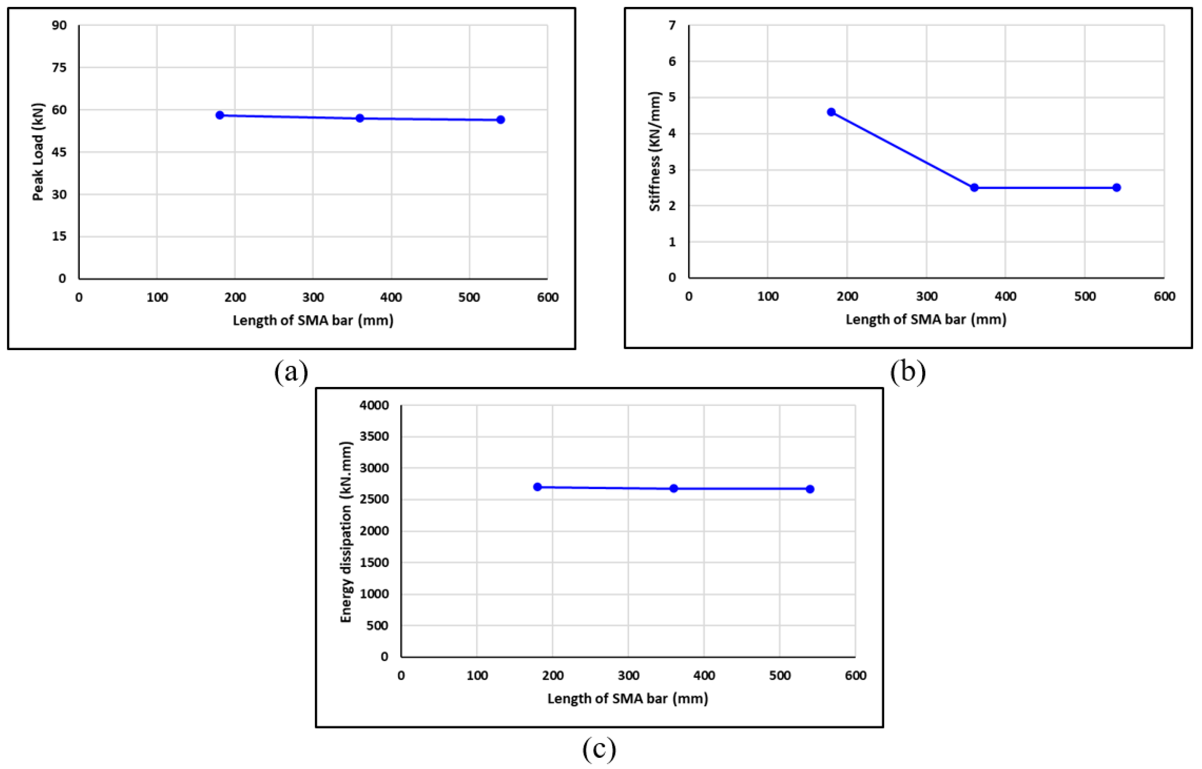
Figure 20.
Effect of SMA bar length of the BCJ on (a) load capacity, (b) stiffness, and (c) energy dissipation.
Figure 20.
Effect of SMA bar length of the BCJ on (a) load capacity, (b) stiffness, and (c) energy dissipation.
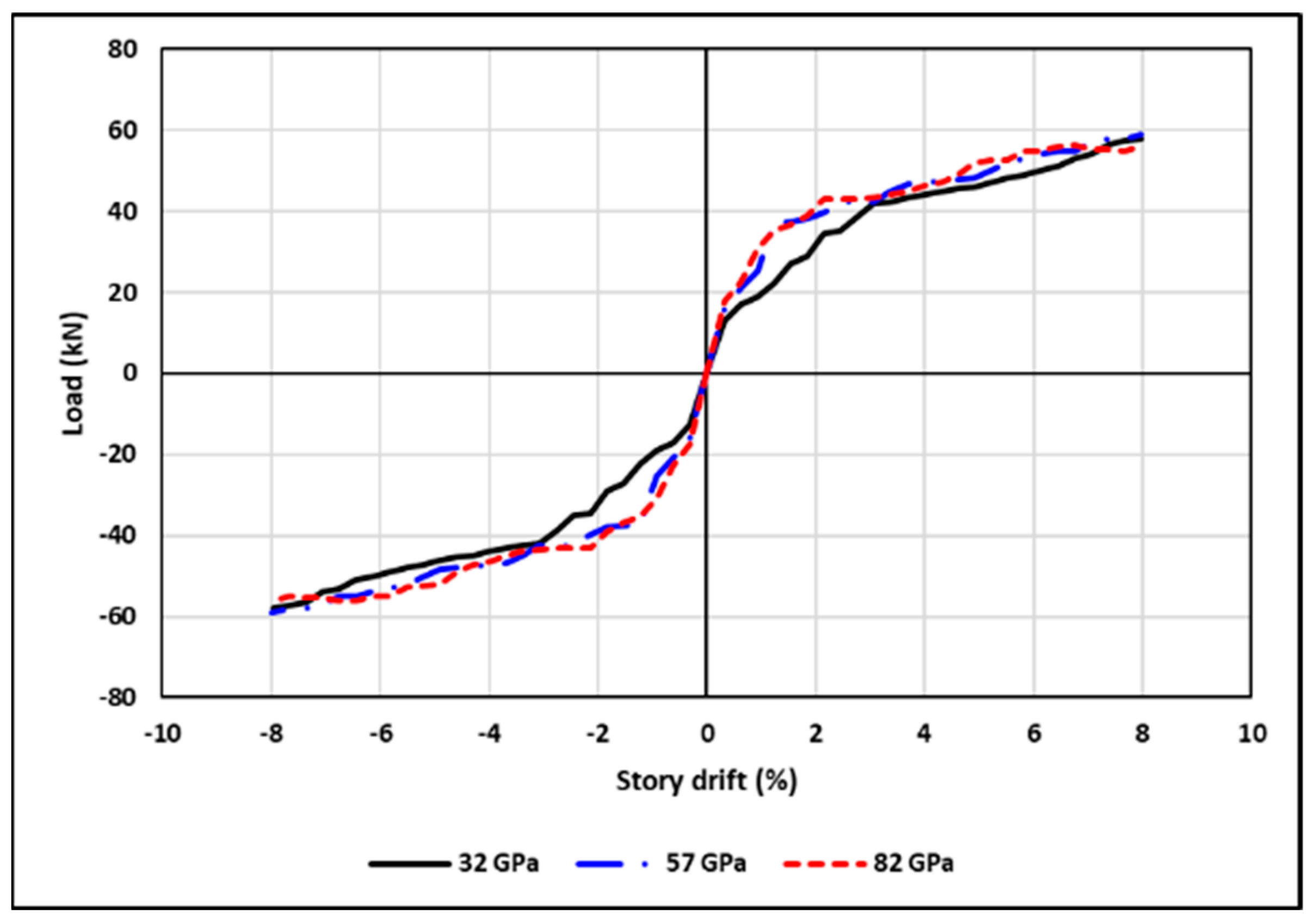
Figure 21.
Numerical beam tip-load versus story drift envelope of the specimens C25-A0-S0N3, C25-A0-S0N3-E57 and C25-A0-S0N3-E82.
Figure 21.
Numerical beam tip-load versus story drift envelope of the specimens C25-A0-S0N3, C25-A0-S0N3-E57 and C25-A0-S0N3-E82.
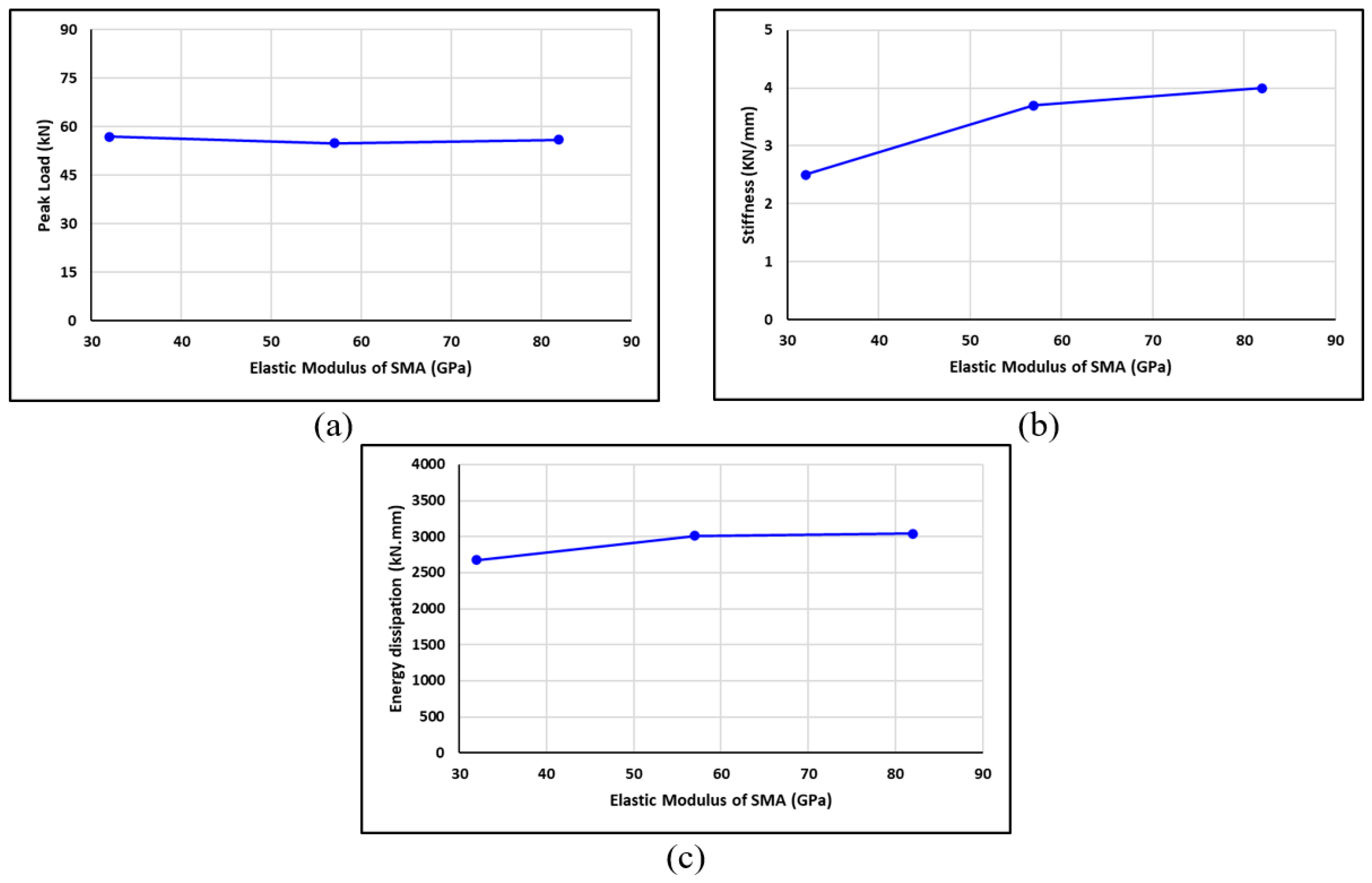
Figure 22.
Effect of SMA elastic modulus of the BCJ on (a) load capacity, (b) stiffness, and (c) energy dissipation.
Figure 22.
Effect of SMA elastic modulus of the BCJ on (a) load capacity, (b) stiffness, and (c) energy dissipation.
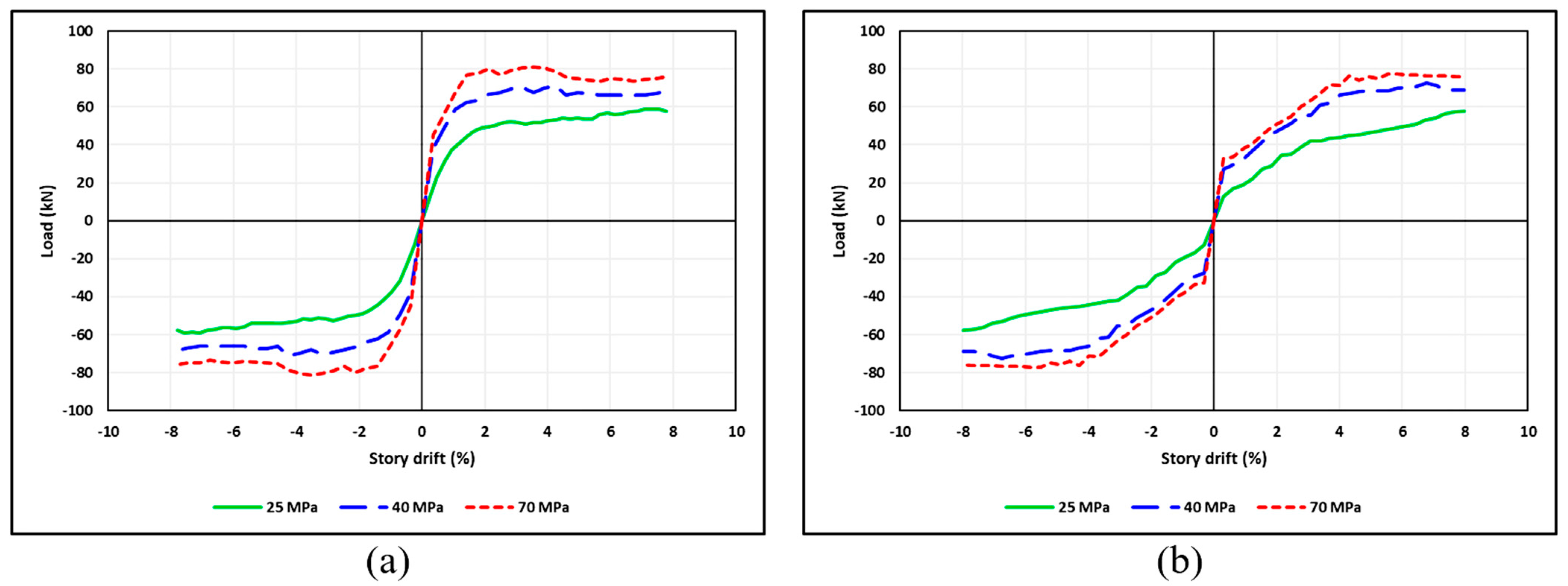
Figure 23.
Numerical beam tip-load versus story drift envelopes of the specimens (a) C25-A0-S3N0, C40-A0-S3N0 and C70-A0-S3N0 (b) C25-A0-S0N3, C40-A0-S0N3 and C70-A0-S0N3.
Figure 23.
Numerical beam tip-load versus story drift envelopes of the specimens (a) C25-A0-S3N0, C40-A0-S3N0 and C70-A0-S3N0 (b) C25-A0-S0N3, C40-A0-S0N3 and C70-A0-S0N3.
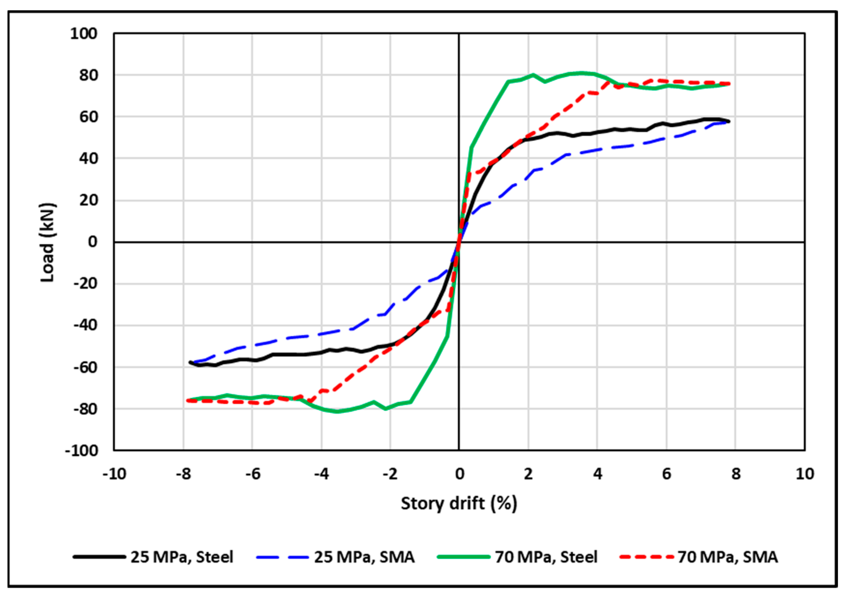
Figure 24.
Comparison of effect of concrete strength on the behavior of BCJ between reinforced with steel and SMA.
Figure 24.
Comparison of effect of concrete strength on the behavior of BCJ between reinforced with steel and SMA.
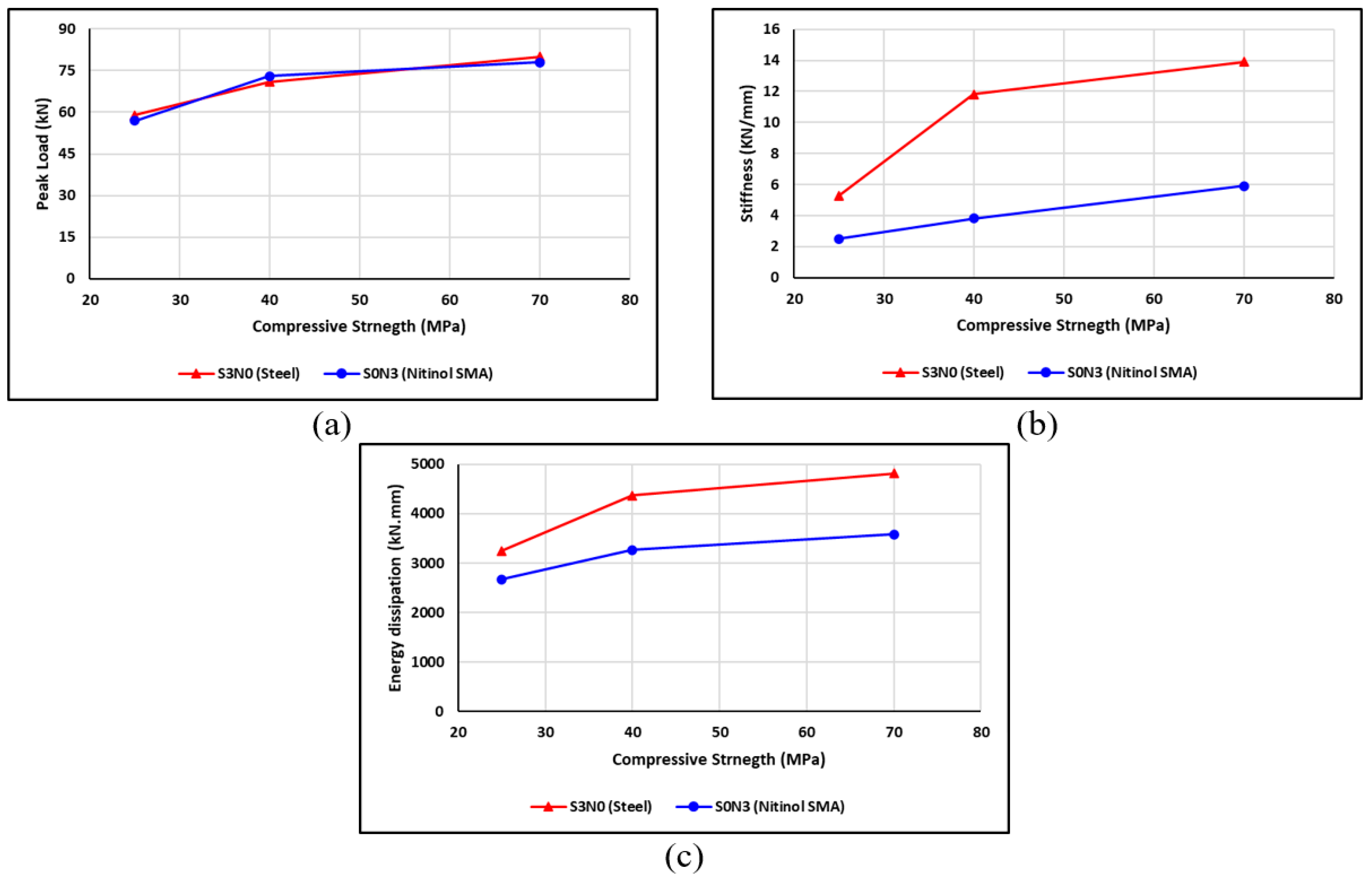
Figure 25.
Effect of compressive strength of concrete of the BCJ on (a) load capacity, (b) stiffness, and (c) energy dissipation.
Figure 25.
Effect of compressive strength of concrete of the BCJ on (a) load capacity, (b) stiffness, and (c) energy dissipation.
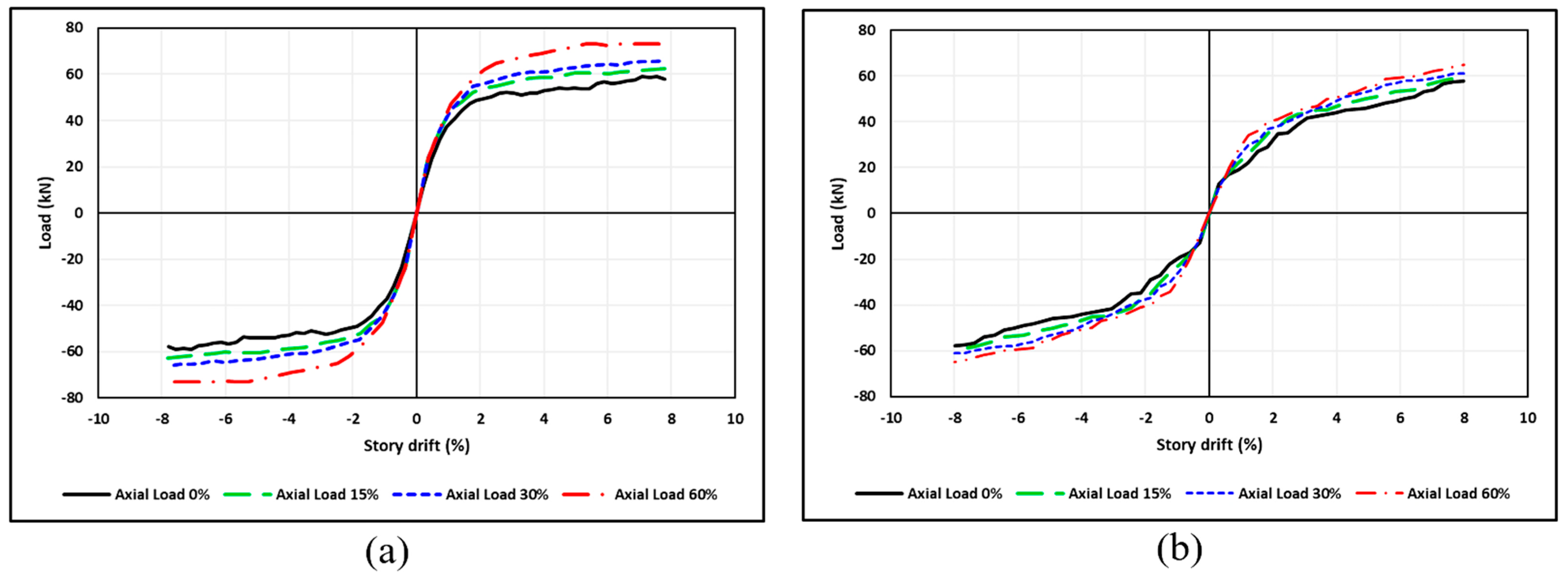
Figure 26.
Numerical beam tip-load versus story drift envelopes of the BCJ (a) C25-A0-S3N0, C25-A15-S3N0, C25-A30-S3N0 and C25-A60-S3N0 specimens; (b) C25-A0-S0N3, C25-A15-S0N3, C25-A30-S0N3 and C25-A60-S0N3 specimens.
Figure 26.
Numerical beam tip-load versus story drift envelopes of the BCJ (a) C25-A0-S3N0, C25-A15-S3N0, C25-A30-S3N0 and C25-A60-S3N0 specimens; (b) C25-A0-S0N3, C25-A15-S0N3, C25-A30-S0N3 and C25-A60-S0N3 specimens.
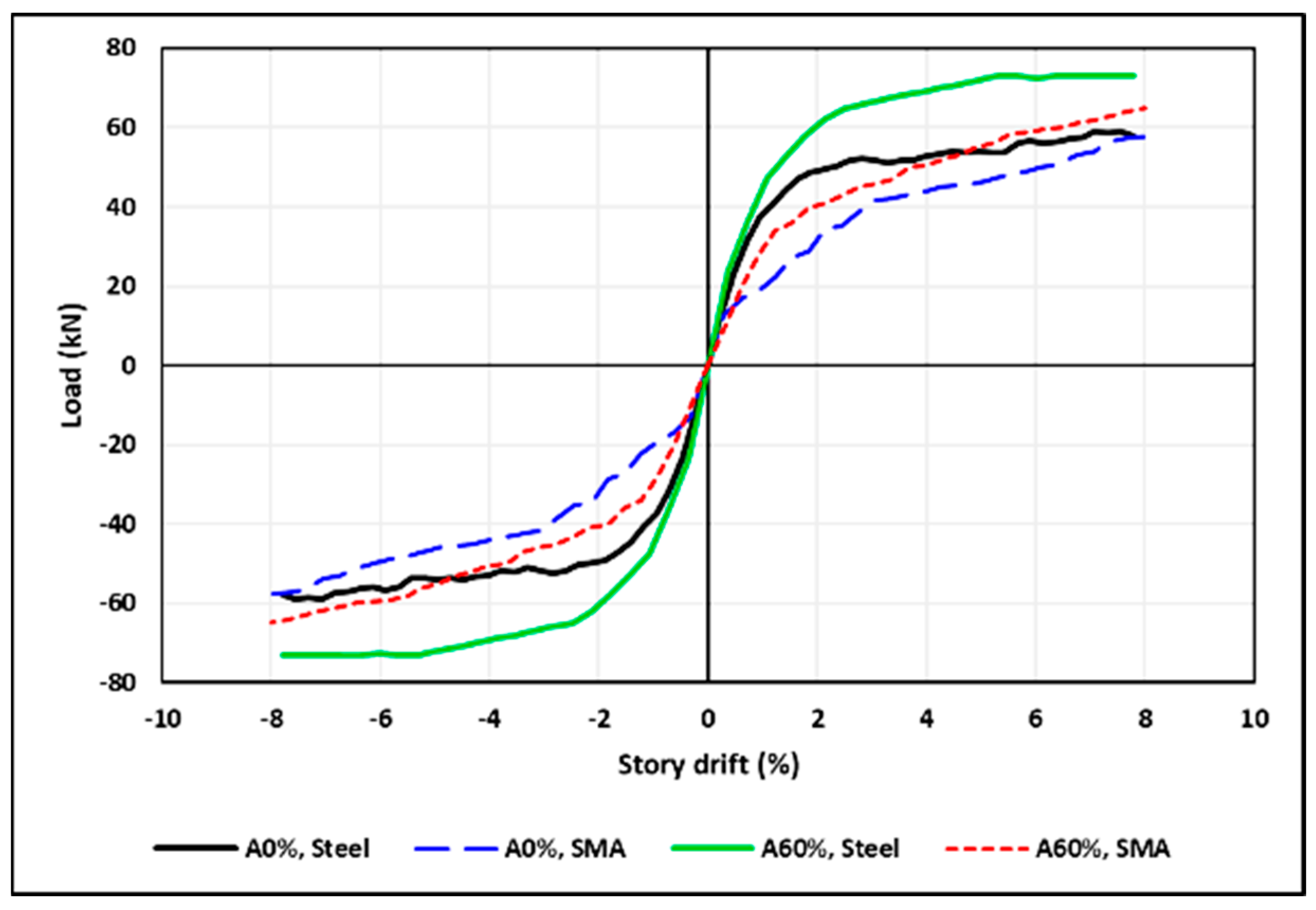
Figure 27.
Effect of axial load level on the load capacity of the BCJ.
Figure 27.
Effect of axial load level on the load capacity of the BCJ.
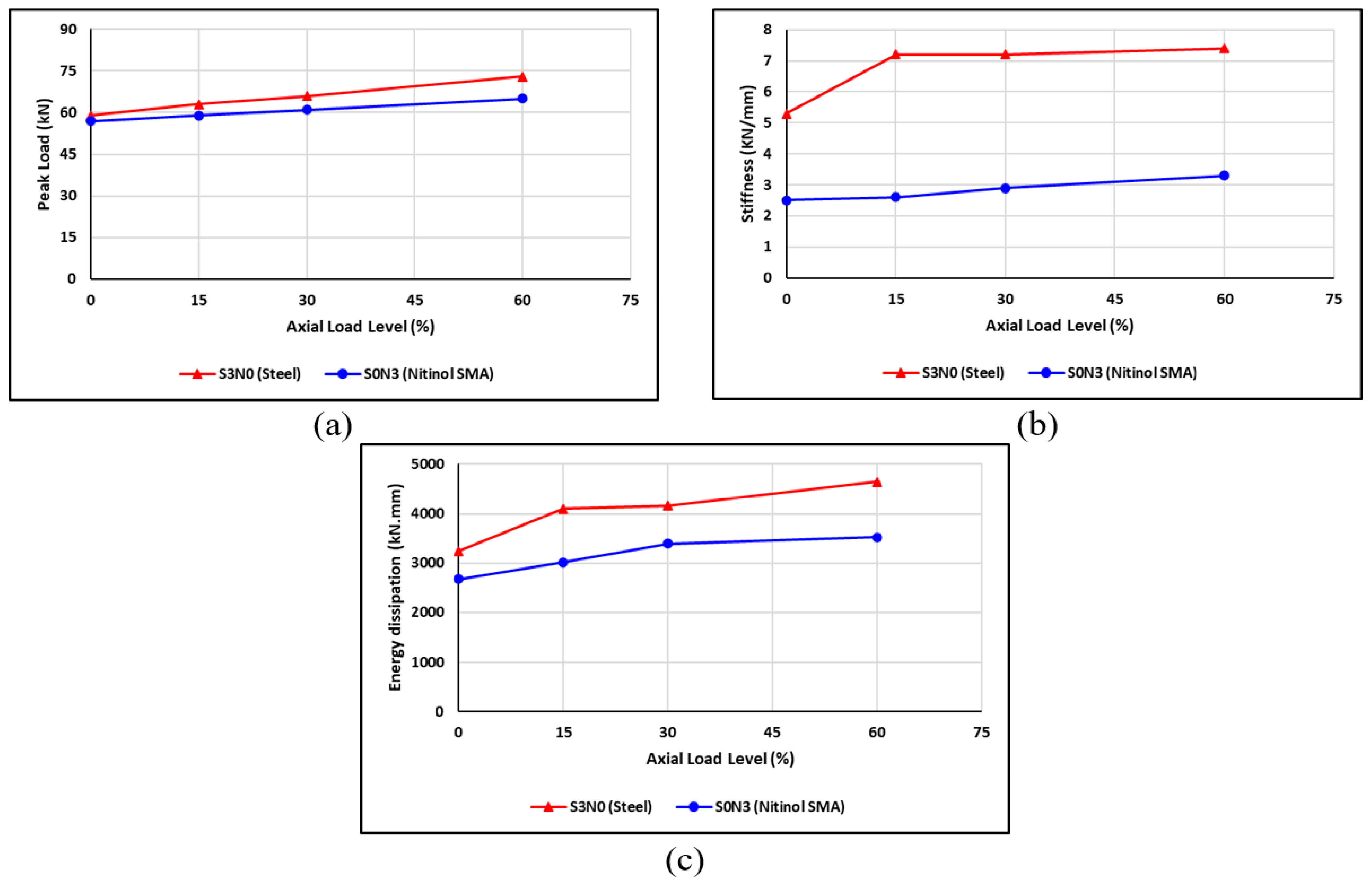
Figure 28.
Effect of axial load level of the BCJ on (a) load capacity, (b) stiffness, and (c) energy dissipation.
Figure 28.
Effect of axial load level of the BCJ on (a) load capacity, (b) stiffness, and (c) energy dissipation.
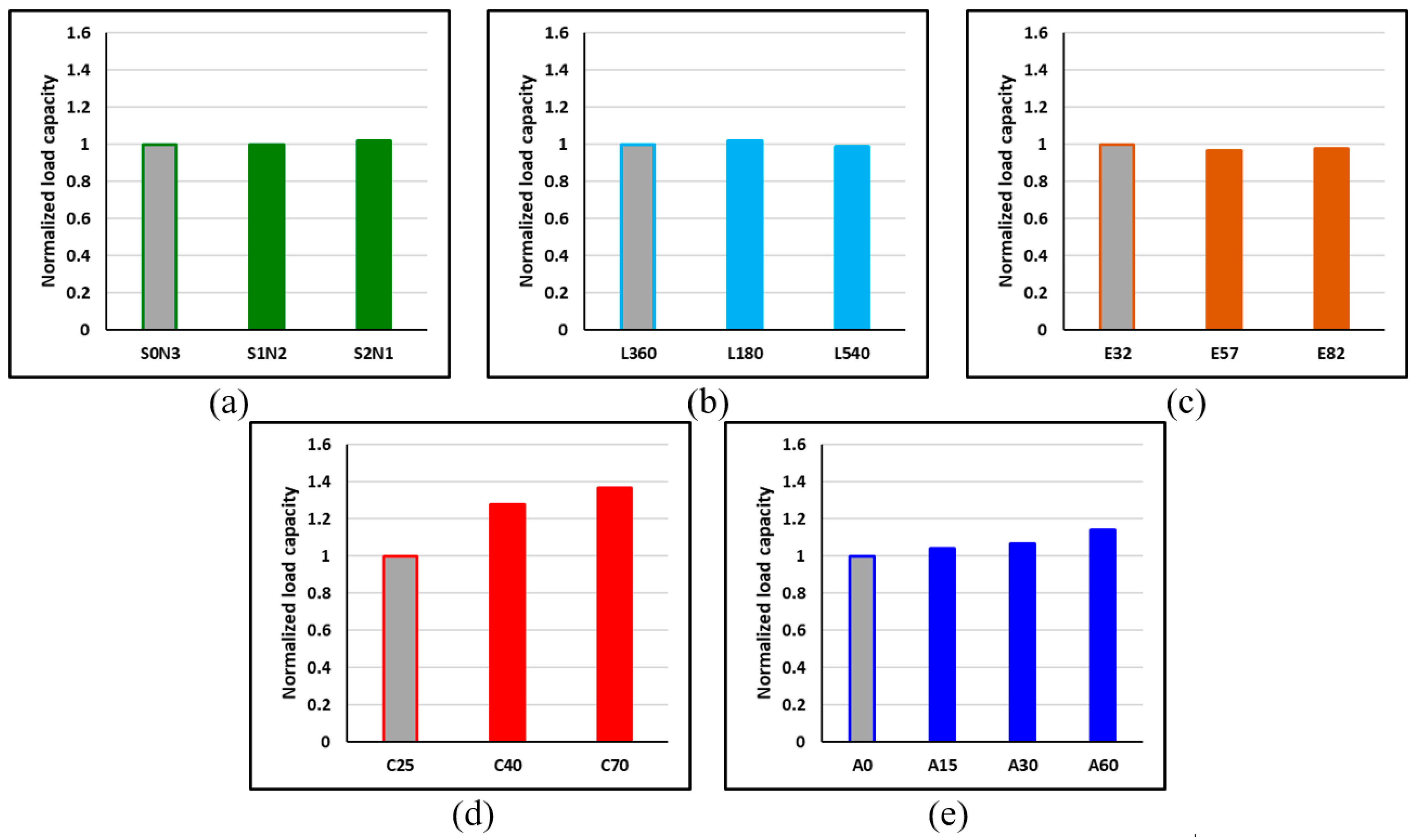
Figure 29.
Comparisons of the effect of SMA on load capacity of the BCJ for the (a) SMA–steel reinforcement ratio, (b) lengths of SMA bars, (c) elastic modulus of SMA, (d) compressive strength of concrete, and (e) axial load level.
Figure 29.
Comparisons of the effect of SMA on load capacity of the BCJ for the (a) SMA–steel reinforcement ratio, (b) lengths of SMA bars, (c) elastic modulus of SMA, (d) compressive strength of concrete, and (e) axial load level.
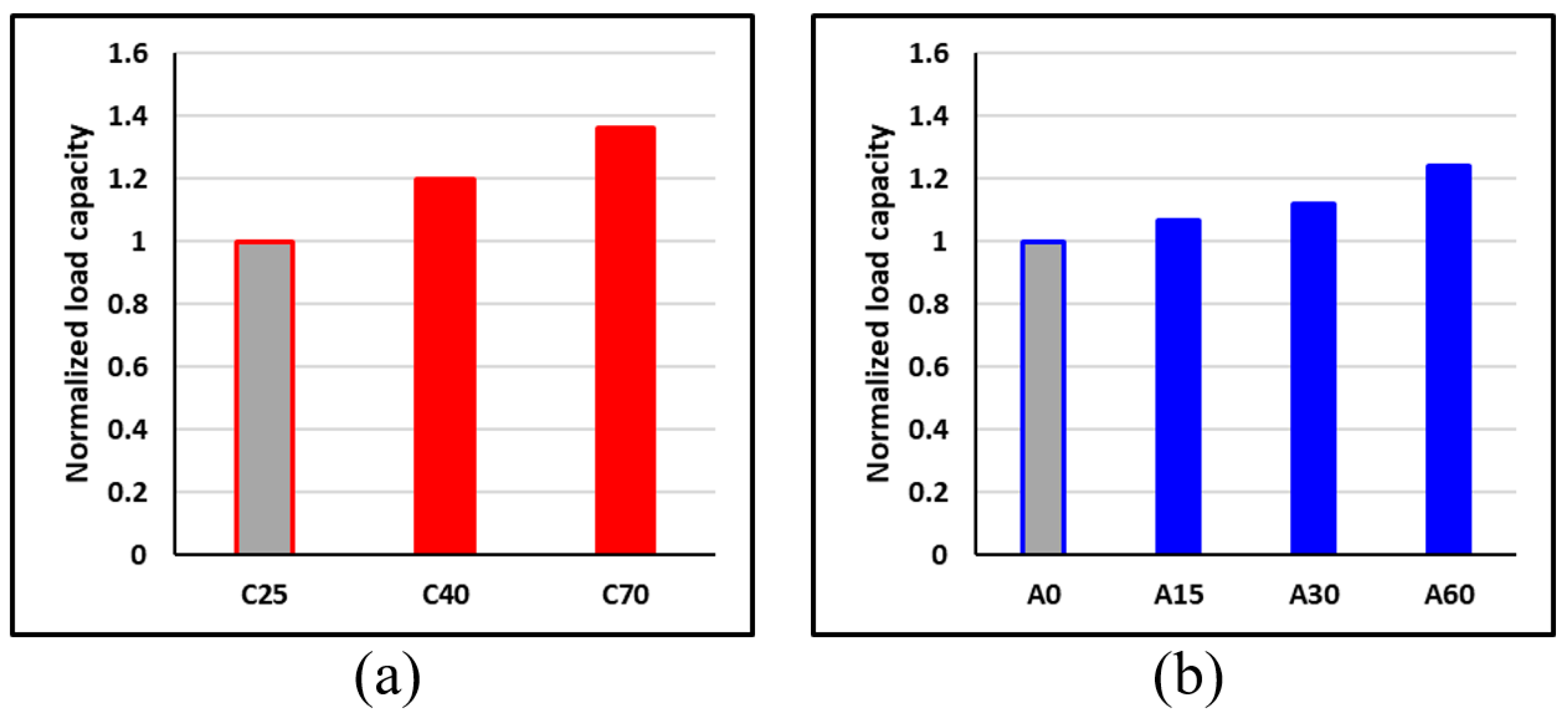
Figure 30.
Comparisons of the effect of steel rebars on load capacity of BCJ for: (a) concrete strength; (b) axial load level.
Figure 30.
Comparisons of the effect of steel rebars on load capacity of BCJ for: (a) concrete strength; (b) axial load level.
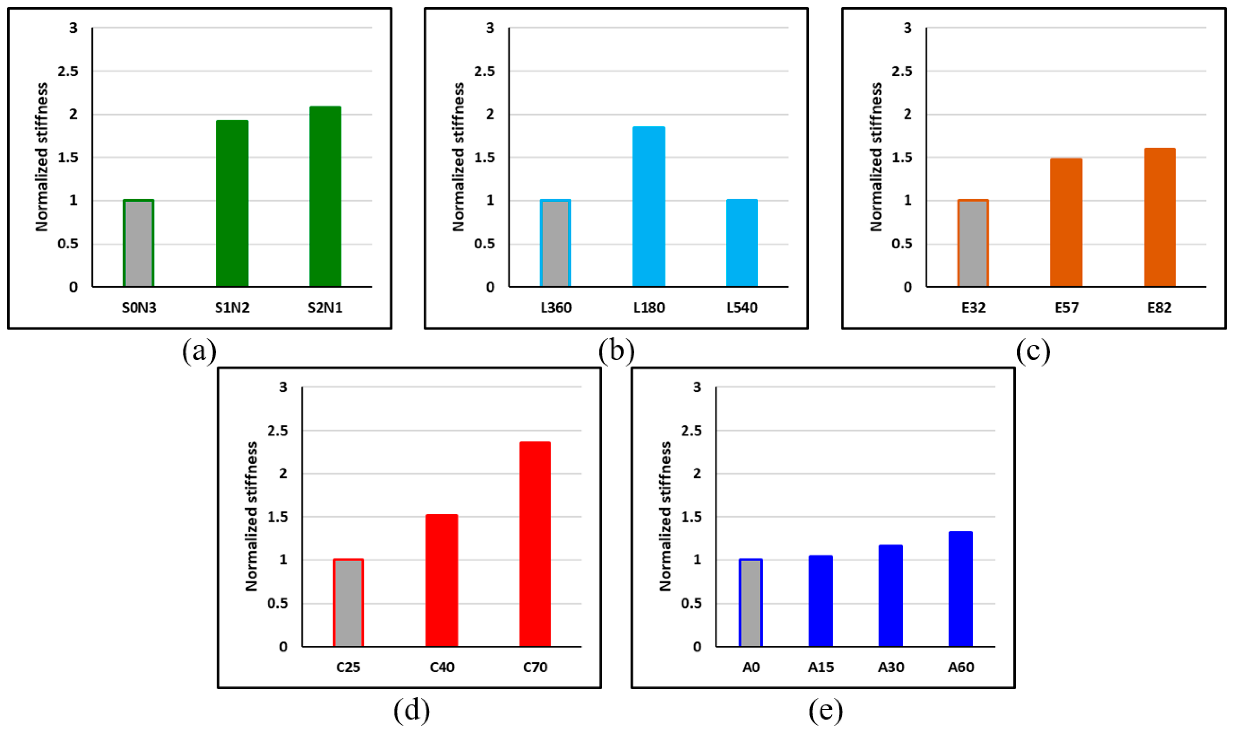
Figure 31.
Comparisons of the effect of SMA on stiffness of the BCJ for the (a) SMA–steel reinforcement ratio, (b) lengths of SMA, (c) elastic modulus of elasticity of SMA, (d) compressive strength of concrete, and (e) axial load level.
Figure 31.
Comparisons of the effect of SMA on stiffness of the BCJ for the (a) SMA–steel reinforcement ratio, (b) lengths of SMA, (c) elastic modulus of elasticity of SMA, (d) compressive strength of concrete, and (e) axial load level.
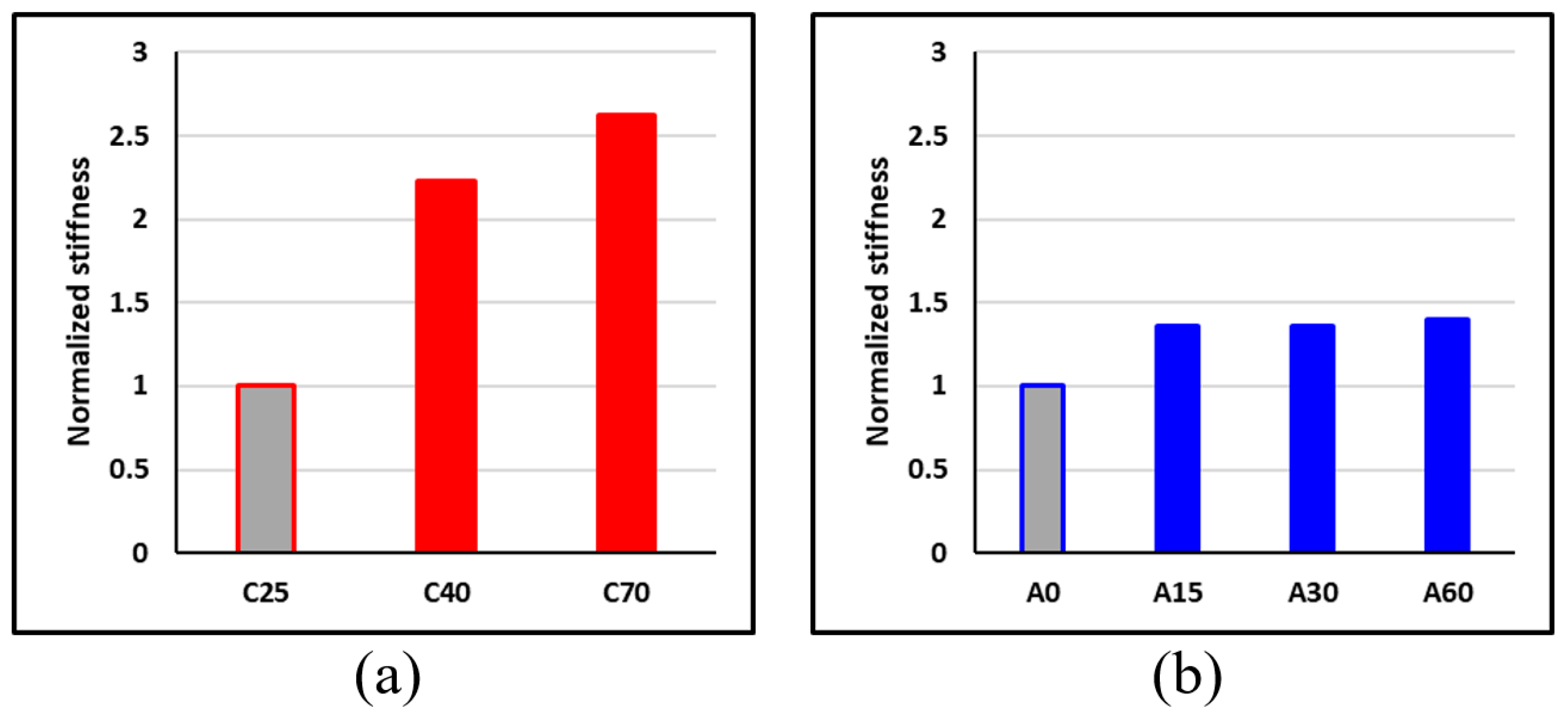
Figure 32.
Comparisons of the effect of steel rebars on stiffness of BCJ for: (a) concrete strength; (b) axial load level.
Figure 32.
Comparisons of the effect of steel rebars on stiffness of BCJ for: (a) concrete strength; (b) axial load level.
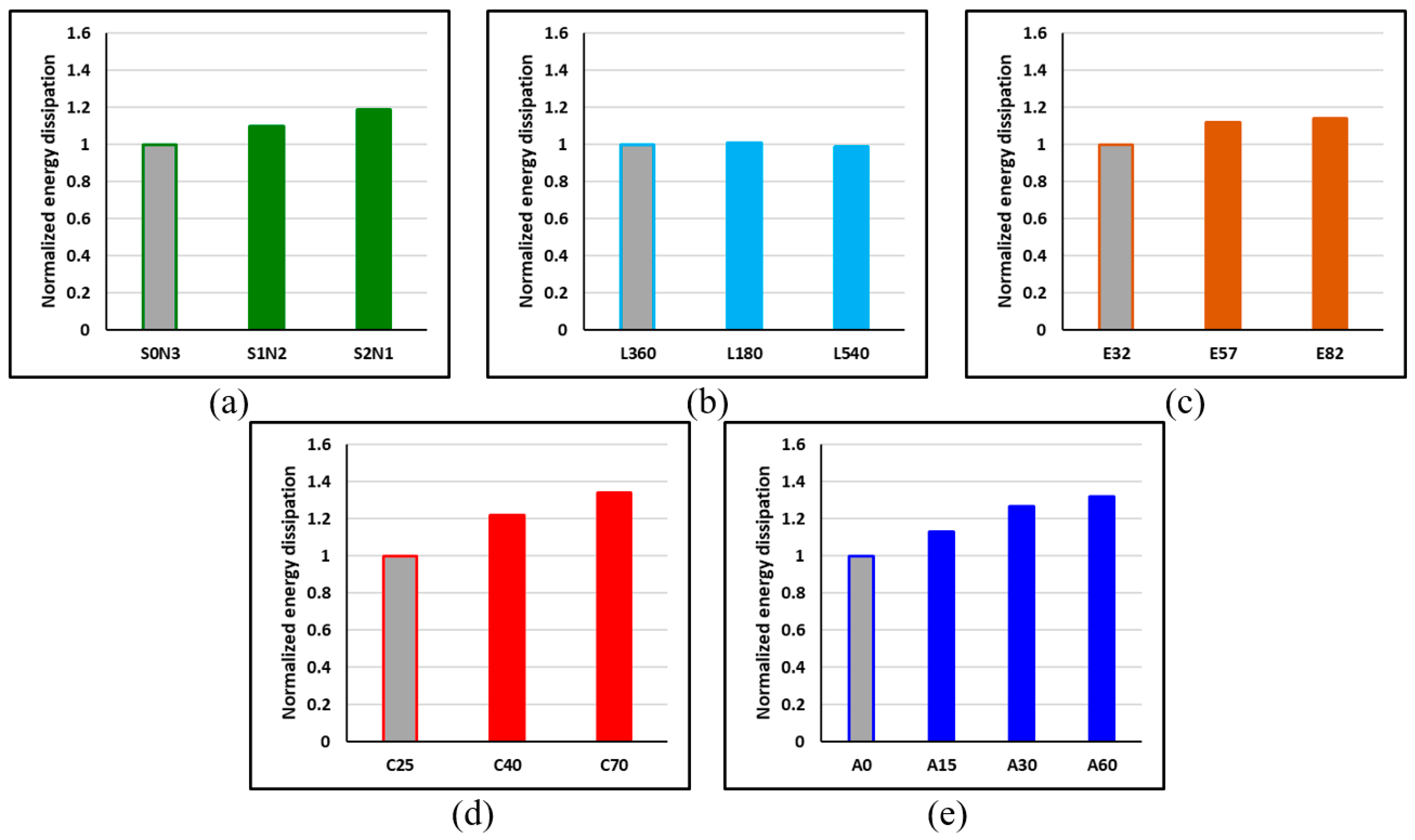
Figure 33.
Comparisons of the effect of SMA on energy dissipation of the BCJ for the (a) SMA–steel reinforcement ratio, (b) lengths of SMA, (c) elastic modulus of SMA, (d) compressive strength of concrete, and (e) axial load level.
Figure 33.
Comparisons of the effect of SMA on energy dissipation of the BCJ for the (a) SMA–steel reinforcement ratio, (b) lengths of SMA, (c) elastic modulus of SMA, (d) compressive strength of concrete, and (e) axial load level.
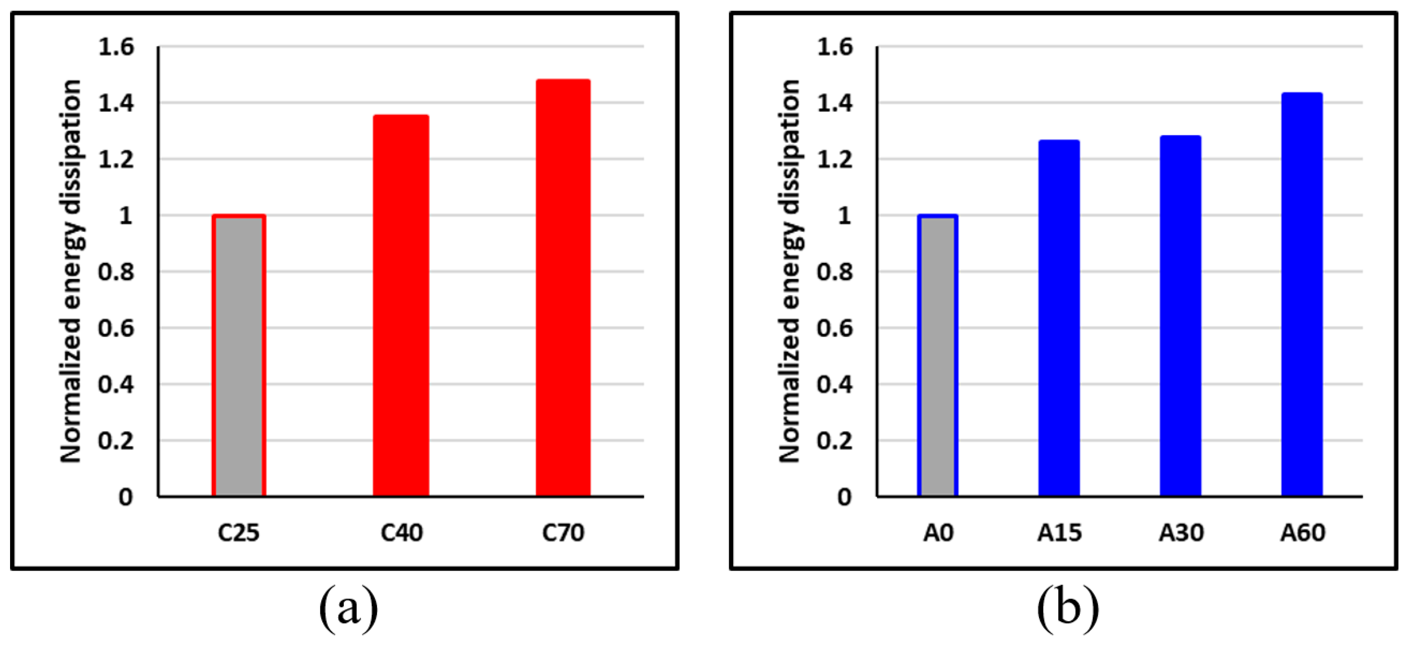
Figure 34.
Comparisons of the effect of steel rebars on the energy dissipation of BCJ for: (a) concrete strength; (b) axial load level.
Figure 34.
Comparisons of the effect of steel rebars on the energy dissipation of BCJ for: (a) concrete strength; (b) axial load level.
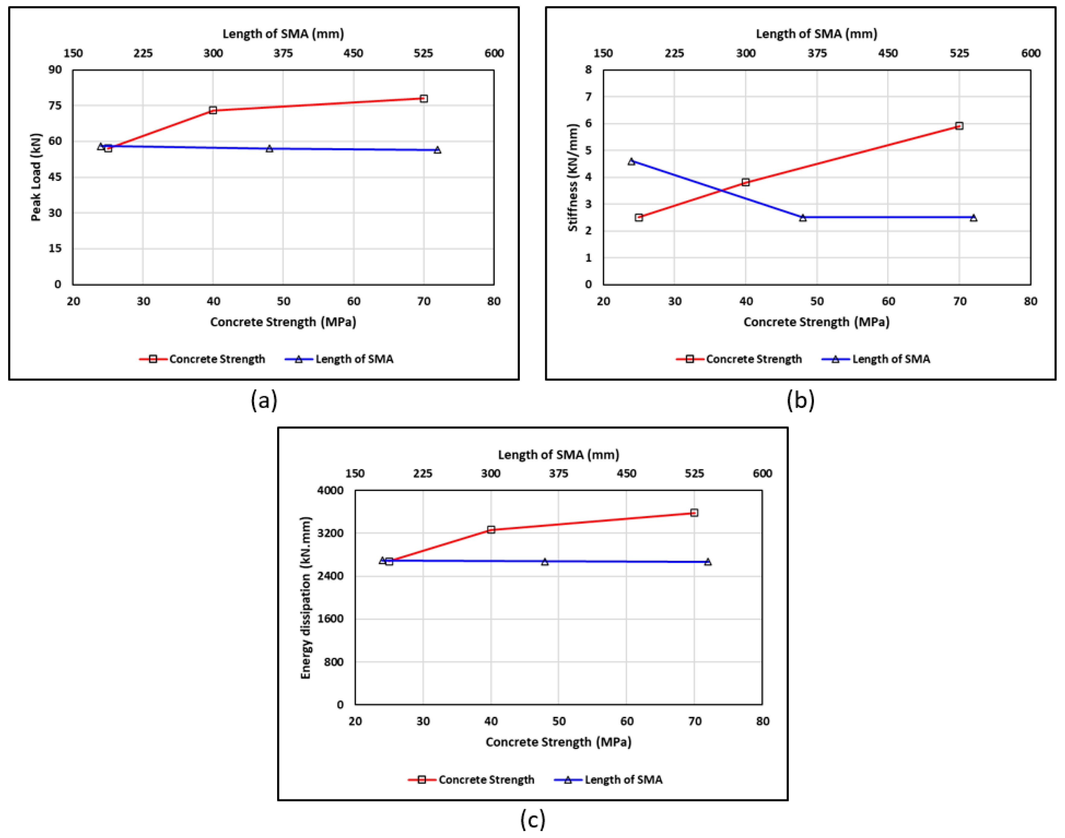
Figure 35.
Comparisons of the effect of the length of SMA and concrete strength parameters on the BCJ for: (a) peak load, (b) stiffness, and (c) energy dissipation.
Figure 35.
Comparisons of the effect of the length of SMA and concrete strength parameters on the BCJ for: (a) peak load, (b) stiffness, and (c) energy dissipation.
Table 1.
Parameters of damage–plasticity model.
Table 1.
Parameters of damage–plasticity model.
| Dilation Angle | Eccentricity | fb0/fc0 | k | Viscosity Parameter |
| 40 | 0.1 | 1.16 | 0.667 | 0 |
Table 2.
Mechanical properties of SMA bars used in ABAQUS.
Table 2.
Mechanical properties of SMA bars used in ABAQUS.
| Start of Transformation (Loading) | End of Transformation (Loading) | Start of Transformation (Unloading) | End of Transformation (Unloading) | Young’s Modulus | Transformation Strain |
|---|
| | | | EA | |
|---|
| 450 MPa | 500 MPa | 350 MPa | 180 MPa | 32,000 MPa | 0.055 |
Table 3.
Effect of mesh size on peak load.
Table 3.
Effect of mesh size on peak load.
| Mesh Size (mm) | Number of Elements | Numerical Peak Load (kN) | Ratio of Numerical to Experimental Peak Loads |
|---|
| 50 | 5387 | 72.4 | 1.112 |
| 40 | 9139 | 69.8 | 1.072 |
| 30 | 11,967 | 66.3 | 1.018 |
| 20 | 66,521 | 65.9 | 1.012 |
Table 4.
Comparison between the numerical and experimental values for the RC-BCJ tested.
Table 4.
Comparison between the numerical and experimental values for the RC-BCJ tested.
| Sample ID | Steel-BCJ | SMA-BCJ |
|---|
| | | | | | | |
|---|
| Peak Load (kN) | 65.1 | 66.3 | −1.81% | 66.0 | 68.1 | −3.08% |
| Stiffness (kN/mm) | 5.05 | 4.92 | +2.64% | 1.78 | 1.83 | −2.73% |
| Energy dissipation (kN/m) | 4154 | 4187 | −0.79% | 3580 | 3571 | +0.25% |
Table 5.
The parameters used in the numerical investigation.
Table 5.
The parameters used in the numerical investigation.
| Parameter | Values |
|---|
| SMA–steel Reinforcement Ratio | S2N1 | S1N2 | S0N3 |
| Length of SMA (mm) | 180 | 360 | 540 |
| Elasticity of SMA (Gpa) | 32 | 57 | 82 |
| Concrete Strength (MPa) | 25 | 40 | 70 |
| Axial Load Level (%) | 15% | 30% | 60% |
Table 6.
Details of the specimens used in the numerical investigation.
Table 6.
Details of the specimens used in the numerical investigation.
| # | Parameters | Specimen ID * | Concrete Strength (Mpa) | Axial Load Level | Steel Rebars | Nitinol SMA Rebars | Elastic Modulus of SMA (Gpa) | Length of SMA (mm) |
|---|
| 1 | Control | C25-A0-S3N0 | 25 | 0% | 16 | - | - | - |
| 2 | C25-A0-S0N3 | 25 | 0% | - | 16 | 32 | 360 |
| 3 | SMA–Steel Reinforcement | C25-A0-S1N2 | 25 | 0% | 16 | 16 | 32 | 360 |
| 4 | C25-A0-S2N1 | 25 | 0% | 16 | 16 | 32 | 360 |
| 5 | Length of SMA | C25-A0-S0N3-L180 | 25 | 0% | - | 16 | 32 | 180 |
| 6 | C25-A0-S0N3-L540 | 25 | 0% | - | 16 | 32 | 540 |
| 7 | Elastic Modulus of SMA | C25-A0-S0N3-E57 | 25 | 0% | - | 16 | 57 | 360 |
| 8 | C25-A0-S0N3-E82 | 25 | 0% | - | 16 | 82 | 360 |
| 9 | Concrete Compressive Strength | C40-A0-S3N0 | 40 | 0% | 16 | - | - | - |
| 10 | C70-A0-S3N0 | 70 | 0% | 16 | - | - | - |
| 11 | C40-A0-S0N3 | 40 | 0% | - | 16 | 32 | 360 |
| 12 | C70-A0-S0N3 | 70 | 0% | - | 16 | 32 | 360 |
| 13 | Axial Load Level | C25-A15-S3N0 | 25 | 15% | 16 | - | - | - |
| 14 | C25-A30-S3N0 | 25 | 30% | 16 | - | - | - |
| 15 | C25-A60-S3N0 | 25 | 60% | 16 | - | - | - |
| 16 | C25-A15-S0N3 | 25 | 15% | - | 16 | 32 | 360 |
| 17 | C25-A30-S0N3 | 25 | 30% | - | 16 | 32 | 360 |
| 18 | C25-A60-S0N3 | 25 | 60% | - | 16 | 32 | 360 |
Table 7.
Numerical test results of the BCJ investigated.
Table 7.
Numerical test results of the BCJ investigated.
| # | Parameter | Specimen ID | Peak Load (kN) | Stiffness (kN/mm) | Energy Dissipated (kN/mm) |
|---|
| 1 | Control | C25-A0-S3N0 | 59 | 5.3 | 3247 |
| 2 | C25-A0-S0N3 | 57 | 2.5 | 2677 |
| 3 | SMA–steel reinforcement | C25-A0-S1N2 | 57 | 4.8 | 2956 |
| 4 | C25-A0-S2N1 | 58 | 5.2 | 3194 |
| 5 | Length of SMA | C25-A0-S0N3-L180 | 58 | 4.6 | 2699 |
| 6 | C25-A0-S0N3-L540 | 57 | 2.5 | 2673 |
| 7 | Elastic modulus of SMA | C25-A0-S0N3-E57 | 55 | 3.7 | 3011 |
| 8 | C25-A0-S0N3-E82 | 56 | 4.0 | 3043 |
| 9 | Concrete Compressive Strength | C40-A0-S3N0 | 71 | 11.8 | 4375 |
| 10 | C70-A0-S3N0 | 80 | 13.9 | 4818 |
| 11 | C40-A0-S0N3 | 73 | 3.8 | 3269 |
| 12 | C70-A0-S0N3 | 78 | 5.9 | 3585 |
| 13 | Axial load level | C25-A15-S3N0 | 63 | 7.2 | 4103 |
| 14 | C25-A30-S3N0 | 66 | 7.2 | 4167 |
| 15 | C25-A60-S3N0 | 73 | 7.4 | 4641 |
| 16 | C25-A15-S0N3 | 59 | 2.6 | 3014 |
| 17 | C25-A30-S0N3 | 61 | 2.9 | 3394 |
| 18 | C25-A60-S0N3 | 65 | 3.3 | 3522 |


